US4708836A - Process for producing an artificial cranium and a prosthetic head - Google Patents
Process for producing an artificial cranium and a prosthetic headDownload PDFInfo
- Publication number
- US4708836A US4708836AUS06/841,821US84182186AUS4708836AUS 4708836 AUS4708836 AUS 4708836AUS 84182186 AUS84182186 AUS 84182186AUS 4708836 AUS4708836 AUS 4708836A
- Authority
- US
- United States
- Prior art keywords
- cranium
- mould
- producing
- head
- core
- Prior art date
- Legal status (The legal status is an assumption and is not a legal conclusion. Google has not performed a legal analysis and makes no representation as to the accuracy of the status listed.)
- Expired - Fee Related
Links
Images


Classifications
- G—PHYSICS
- G09—EDUCATION; CRYPTOGRAPHY; DISPLAY; ADVERTISING; SEALS
- G09B—EDUCATIONAL OR DEMONSTRATION APPLIANCES; APPLIANCES FOR TEACHING, OR COMMUNICATING WITH, THE BLIND, DEAF OR MUTE; MODELS; PLANETARIA; GLOBES; MAPS; DIAGRAMS
- G09B23/00—Models for scientific, medical, or mathematical purposes, e.g. full-sized devices for demonstration purposes
- G09B23/28—Models for scientific, medical, or mathematical purposes, e.g. full-sized devices for demonstration purposes for medicine
- G09B23/30—Anatomical models
- Y—GENERAL TAGGING OF NEW TECHNOLOGICAL DEVELOPMENTS; GENERAL TAGGING OF CROSS-SECTIONAL TECHNOLOGIES SPANNING OVER SEVERAL SECTIONS OF THE IPC; TECHNICAL SUBJECTS COVERED BY FORMER USPC CROSS-REFERENCE ART COLLECTIONS [XRACs] AND DIGESTS
- Y10—TECHNICAL SUBJECTS COVERED BY FORMER USPC
- Y10S—TECHNICAL SUBJECTS COVERED BY FORMER USPC CROSS-REFERENCE ART COLLECTIONS [XRACs] AND DIGESTS
- Y10S264/00—Plastic and nonmetallic article shaping or treating: processes
- Y10S264/30—Use of anatomy in making a mold or using said mold
Definitions
- the present inventionrelates to an artificial cranium and to a prosthetic head produced from said cranium, as well as to a process for producing said cranium and said head.
- the inventionhas a very interesting application in the study of the effectiveness of helmets for motorcyclists and also motorists in the case of racing cars or other competitive vehicles, such as those used in gocarting and the like.
- craniumsused more particularly for pedagogic purposes.
- said craniumsare made from flexible plastics and are generally in two parts, which are assembled along a plane using mortises and tenons.
- the joining planeis chosen so as to make it easy to construct the two parts of the cranium (cavities which are largely open to the outside and no undercuts). It is clear that although such craniums are satisfactory for the study of the anatomy, they do not make it possible to carry out mechanical tests for shock resistance, on the one hand because the materials chosen have characteristics which differ widely from those of true bones and on the other hand because the assembly plane of the two parts in no way corresponds to what occurs anatomically.
- prosthetic headsfor the study of injuries caused by automobile accidents.
- such headsare constituted by a simple external envelope substantially reproducing the external appearance of a true human head within which are placed metal structures in honeycomb form.
- the object of the present inventionis to eliminate these disadvantages by proposing an artifical cranium and a prosthetic head produced from same cranium having the same mechanical behaviour and shape characteristics as a fresh cranium and a real head respectively.
- said craniumis made from a material, whose thickness is such that the compression strength at a point on the artificial cranium is close to the compression strength at the corresponding point of the fresh cranium.
- said materialis an epoxy resin.
- fresh craniummeans the cranium of a living human or animal, or the cranium removed shortly after death, so that its mechanical characteristics are not modified.
- shape characteristicsmeans that the artificial cranium must have the same shape and dimensions as a real human cranium and also the cavities corresponding to the natural cavities of a real human or animal cranium must have the same shape and dimensions as these, except that the thickness of the material used must be adapted for the reason given hereinbefore.
- the external shape of the artificial craniumis identical to that of the fresh cranium.
- the thickness of the material constituting the artificial craniumdiffers from that of the real bone, the internal cavities do not exactly reproduce the cavities of the fresh cranium. However, this is not prejudicial because the differences are small (a few millimeters).
- the craniumcomprising the cranial case and the lower jawbone, so that the material mass constituting the walls of the cranial case is homogeneous and continuous.
- the inventionalso relates to a process for producing an artificial cranium by moulding a first material in a mould which is in several parts, said cranium having at least one cavity, wherein it comprises the following stages:
- the first materialis an epoxy, resin
- the second materialis a material which can be eliminated by dissolving in a solvent, which neither attacks nor dissolves the first material.
- stage (a)comprises:
- test piecehaving the shape of a regular cylinder with the same cross-section as the bone test piece by fixing to the latter at least one member made from a material whose compression modulus of elasticity is known
- the processis more particularly applicable in the case of producing an artificial human cranium, where said cavity is a nasal or cerebral cavity.
- the processalso comprises the following stages, performed before stage (j) and comprising
- the screwis removed and the orbital core extracted from the orbital cavity.
- the artificial cranium to be producedhas a lower jawbone and a cranial case with at least one cavity (this is the case with human craniums, whereof the cranial case has a nasal cavity and a cerebral cavity), the lower jawbone and cranial case are produced separately by moulding.
- the material from which the model cranium is madeis a wax, which has the advantage of being easy to work.
- the inventionalso relates to a prosthetic head.
- a prosthetic headAccording to the main feature of said head, it comprises a cranium like that referred to hereinbefore.
- this headalso comprises at least one soft part with the same shape and mechanical behaviour characteristics as the corresponding soft part of a real head.
- soft partsis used to describe those parts of the head other than the bones, i.e. essentially the brain, eyeballs, ears, nasal pyramid and skin. These various soft parts have the same dimensions (in the case of the skin the same thickness) as the corresponding soft parts of the real head and are made from a material having the same mechanical behaviour (essentially the same hardness) as the real soft parts.
- said materialis a silicone mixed with oil.
- the inventionalso relates to a process for producing said prosthetic head. According to the main feature of this process, it comprises the following stages:
- this processcomprises a supplementary stage, performed before stage (6) and which consists of placing, at a given point of the cranium, a soft part made from a material with the same shape and mechanical strength characteristics as the corresponding soft part of a real head.
- the material from which said soft part is madeis a silicone mixed with oil and the oil quantity in the mixture is adjusted so that the hardness of said soft part is identical to that of the corresponding soft part of a real head.
- the positioning means usedis a support with at one of its ends a boss, whose shape corresponds to that of the occipital foramen and at the other end orientation means able to cooperate with the corresponding orientation means provided in the mould.
- the production of said supportcan comprise the following stages:
- the production of the mouldcomprises the following stages:
- said processcan comprise a supplementary stage, performed before stage (7), consisting of placing a measuring sensor at a given point on the head.
- This sensor(there can be several of them) makes it possible to determine the stresses or accelerations undergone at a given point on the head under the effect of an external stress (shock, noise, etc.).
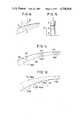
- FIGS. 1a to 1dDiagrammatic sectional views illustrating in a more detailed manner how stages (a) to (c) of the process for producing the artificial cranium are performed.
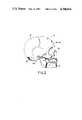
- FIG. 2A diagrammatic profile view of a human head.
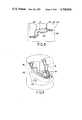
- FIG. 3A diagrammatic sectional view illustrating both the production of the mould for producing the lower jawbone and the production of the latter.
- FIG. 4A diagrammatic perspective view showing the lower jawbone before being extracted from its mould.
- FIG. 5A diagrammatic sectional view illustrating the production of the mould and cores defining the cavities with the aid of a model head.
- FIG. 6A diagrammatic sectional view illustrating the placement of the mould and cores used for producing an artificial head.
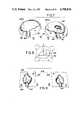
- FIGS. 7a and 7bDiagrammatic perspective views illustrating the countermould used for producing the cerebral core.
- FIG. 8A diagrammatic sectional view showing how the cerebral core is produced by agitation of the countermould illustrated in FIGS. 6a and 6b.
- FIGS. 9a and 9bDiagrammatic perspective views illustrating the countermould used for producing the core corresponding to the nasal cavity.
- FIG. 10A diagrammatic perspective view illustrating the finished artificial cranium, the lower part thereof still being located in the lower part of the mould.
- FIGS. 11a and 11bDiagrammatic perspective views respectively illustrating the lower and upper parts of the mould used for determining the external shape of the cranium.
- FIGS. 12 to 12fDiagrammatic views illustrating the different stages in the production of an artificial cranium according to the invention.
- FIG. 13A diagrammatic sectional view illustrating the production of a prosthetic head from the cranium according to the invention.
- FIG. 14A diagrammatic elevation view showing the finished prosthetic head prior to mould removal thereof.
- FIG. 15A diagrammatic elevation view showing how it is possible to position the different sensors within the prosthetic head.
- an equivalent resin thicknesswas determined so that the compression strength at a given point of the artificial cranium is equal to the compression strength at the corresponding point of the fresh cranium.
- a wax craniumwas produced having the shape and dimensions of a real human cranium (except for the thickness adaptations). This wax cranium was used for producing the moulds for making the synthetic craniums in the process according to the invention.
- a bone test piece 3is removed from the bone wall 1 using a trephine.
- the test piece 3is taken substantially perpendicularly to the bone wall 1 and its cross-section is circular, its diameter being e.g. approximately 8 mm.
- the outer and inner faces of wall 1are rarely parallel at a given point.
- test pieces taken symmetrically (to within 1 or 2 mm) with respect to the plane of symmetry of the craniumare not identical.
- test pieceswere produced of the type shown in FIG. 1b.
- test piece 3At each of the ends of test piece 3 are provided cylindrical elements 7, 9, which adapt perfectly to the shape of test piece 3, thus constituting a test piece 11 having the shape of a regular cylinder, whose diameter is that of test piece 3.
- test pieces 11had a height of 20 mm and a diameter of 8 mm, but it would not pass beyond the scope of the invention to use other values.
- Elements 7 and 9can e.g. be made from araldite CW 216.
- h othe mean height of the bone part
- the cross-section of the bone test piecemay also not be constant and in this case in order to calculate the stress undergone when it is in compression, account is only taken of the minimum cross-section value.
- Test piece 3is then placed under compression, as indicated by arrows F in FIG. 1b.
- the modulus of elasticity E of the complete test piece 11is determined PG,17 and the modulus of elasticity E o of the bone part is determined by the relation: ##EQU1##
- E abeing the modulus of elasticity of elements 7 and 9 (e.g. 760 hbars in the case of araldite). This value can either already be known, or can be determined by a prior test. It was consequently possible to determine that the bones of the cranial case had modulus of elasticity values varying significantly from one point to the next, the minimum values being approximately 100 hbar and the maximum values approximately 800 hbar.
- the following stageconsists of the determination of the equivalent thicknesses of the material forming the artificial cranium, so that at a given point, the resistance to mechanical stressing is the same as that of the real bone.
- resins of the type referred to hereinbeforehaving a compression modulus of elasticity of approximately 600 hbar.
- the equivalent thickness h r of the resinis determined by the formula: ##EQU2## E r being the modulus of elasticity of the resin.
- continuous linesillustrate three test pieces 13, 15, 17 and mixed lines the equivalent resin thickness necessary to have the same compression strength.
- the resin elements 13a, 17aare thicker than test pieces 13, 17 and elements 15a thinner than test piece 15.
- FIG. 1dshows in continuous line form the bone wall 1 of the real cranium, whilst the broken lines illustrate the corresponding wall 1a of the artificial cranium.
- Wall 1has an outer face 19 and an inner face 21. It is pointed out that preferably the artificial cranium has the same external shape as the real cranium. Consequently the outer face 19a of wall 1a coincides with face 19. Its inner face 21a differs from face 21 and passes through the ends of elements 13a, 15a, 17a located inside the cranium.
- the wax cranium used for producing the moulds and countermoulds employed in the inventionhas a shape, at a given zone, identical to that of wall 1a of FIG. 1d.
- FIG. 2diagrammatically represents a human cranium 2 and which comprises two parts which are movable with respect to one another, namely a lower jawbone 4 and a cranial case 6.
- lower jawbone 4 and cranial case 6are produced separately, because the jawbone has few reentrant angles, few undercuts and no cavity, so that it can easily be produced by moulding using conventional methods.
- It is more difficult to produce the cranial casebecause it has a certain number of cavities, namely the cerebral cavity 8, nasal cavity 10 and orbital cavities 12, 14. These cavities communicate with the outside by holes which have a small diameter compared with their dimensions (cervical hole 16 for cerebral cavity 8), so that a special method had to be developed.
- This operationessentially comprises two stages, firstly producing the mould from the wax jawbone and then producing the resin jawbone using said mould.
- FIG. 3shows that firstly the lower jawbone 4 is placed in a plaster material 18 within a container 20.
- the plaster materialis fashioned before hardening, so that the joining plane follows a line corresponding approximately to half the height of the jawbone.
- Over the jawbone 4 and plaster material 18is then poured material 22 which will form the first part of the mould taking as the joining plane the line referred to hereinbefore.
- FIG. 4shows the lower jawbone 4 as occurs in the lower part 18 of the mould following the hardening of the resin and after removing the upper part 22 of the mould. It is possible to see three centring pins 30 making it possible to position the two parts of the mould with respect to one another. In view of the flexibility of the material used, the operator can easily move apart the edges of the silicone material of jawbone 4 by simply exerting pressure with the fingers, which facilitates extraction thereof.
- moulds and countermouldsused for producing the resin cranial case, said moulds and countermoulds being produced from impressions taken of the wax cranium.
- the cerebral cavity 8 of the wax cranial case 6is filled with a mass 32 of a product, which can be that used for producing the lower jawbone.
- This massis introduced in liquid form through the cervical holes 16 and, still through the latter, a positioning means 36 is introduced and in the presently described example it is constituted by a rigid rod having a square cross-section.
- a positioning rod 40which is also rigid and has a square cross-section.
- cores 42, 44which are advantageously also made from silicone.
- FIG. 5shows that in cores 42, 44 are placed plates 46, 48, each provided with a tapped hole 50, 52 respectively. The function of these perforated plates will be explained hereinafter in connection with the description of the production of a resin cranium.
- This mould 43comprises a lower part 54 and an upper part 56; it being produced in known manner by taking as the joining plane a line passing through the zygomatic process.
- Elements 54 and 56are produced by pouring silicone into a container constituted by a base 55 surmounted by a cylindrical sleeve 57. Mould removal is extremely easy due to the flexibility of this material, as can be seen in the right-hand part of FIG. 5. By simple finger pressure, the operator is able to deform part of the upper mould 56 to disengage it from the cranium.
- FIG. 5also shows that during the production of the lower part 54 of the mould, the ends of rods 36 and 40 are located outside the cerebral and nasal cavities and are consequently set in the silicone mass constituting the lower part 54 of the mould. Following the extraction of the latter, said rods leave traces 37, 41 respectively (cf. FIG. 11a) which will be used for the positioning of the cores during the production of the resin cranium.
- traces 37, 41respectively (cf. FIG. 11a) which will be used for the positioning of the cores during the production of the resin cranium.
- elements 54 and 56have hardened, they are extracted whilst deforming them if necessary.
- the wax craniumis then destroyed so as to recover core 32 equipped with its positioning rod 36, together with core 38 equipped with its positioning rod 40. Extraction also takes place of the orbital cores 42, 44 equipped with plates 46, 48.
- FIG. 6shows the lower part 54 of the mould having one or more centring pins 58, which are to be received in corresponding holes 60 of the upper part 56.
- the latteris equipped with one or more centring pins 62 received in the correspondingly shaped holes 64 provided on lower part 54.
- the first stageconsists of producing a cerebral core 66 and a nasal core 68 made from a material which can be dissolved in a solvent which does not dissolve resin.
- a mineral or organic saltwhich is soluble in water, e.g. sodium thiosulphate to which glucose has been added, potassium alum, etc., because the resin is not soluble in water.
- FIGS. 7a and 7bshow that the countermould 70 of the cerebral cavity comprises two parts 72, 74, which can be assembled by centring pins 76 received in holes 78. After producing the countermould 70 with the aid of core 32 poured into the wax cranium, positioning rod 36 is maintained in place, so that the countermould 70 has a passage 80.
- the cerebral coreis produced as follows. Countermould 70 is closed and the necessary quantity of soluble material is introduced into cavity 82, which is in two parts 82a, 86b corresponding to the two parts 72, 74 of countermould 70. The positioning rod 36 is then introduced into recess 80, which is also in two parts. It should be noted that this rod 36 is not necessarily the same as that used for producing the initial impressions with the wax cranium and it is merely necessary that it has the same geometry.
- the countermouldis then moved in all directions, in order that the material covers the inner walls of cavity 82 and forms a film which solidifies during said movement, in order to obtain hollow cores in the manner illustrated in FIG. 7b.
- This methodmakes it possible to save material.
- the nasal core 68is made in the same way in a countermould 84 in two parts 86, 88 (FIG. 9). The latter are reciprocally positioned with the aid of centring pins 87 received in holes 89.
- rod 40is not a fitted rod and is made from the same soluble material as core 68, so as to facilitate the extraction of the resin cranium once it has been completed.
- FIG. 6also shows that the upper part 56 of the mould has a hole 90 for casting the resin, as well as a vent 92.
- FIGS. 12a to 12fsummarize the different stages of the process according to the invention.
- FIG. 12ashows that the lower part 54 of the mould is firstly placed in base 55, the part 54 having recesses 37 and 41 for the positioning rods of the cerebral core and nasal core respectively. Once the latter have been produced in their countermoulds, as has been described with reference to FIGS. 7 to 9, the cerebral core 66 is fitted by introducing its rod 36 into recess 37 and the nasal core 68 by introducing its positioning rod 40 into recess 41 (FIG. 12b). The upper part 56 of the mould is then introduced and in it are fixed the orbital cores 12, 14 using screws 47, 49 (FIG. 12c). The two mould parts 54, 56 are also fixed to one another.
- stages (h) to (n)can be repeated several times without it being necessary to repeat stages (a) to (g).
- FIG. 13A description will now be given of the production of a prosthetic head according to the invention with reference to FIGS. 13 to 15.
- a cranium 94(FIG. 13) is firstly produced in accordance with the method described hereinbefore.
- the following stageconsists of placing a certain number of soft parts on said cranium.
- soft partsis used to designate the non-bony parts of the head, i.e. essentially the brain, eyeballs, nose, ears and skin.
- useis made of a material having the same hardness as the corresponding soft part of a real head.
- the determination of the hardness of the soft partscan take place directly on a living person with regards to the skin, ears and nose or during a a surgical operation with regards to the brains and eyeballs. This determination can be carried out with a durometer.
- a silicone to which oil has been addedthe hardness being adjusted by varying the oil quantity in the mixture.
- silicone RHODORSIL RTV 11 504 A and oil 47 V 50marketed by Rhone Poulenc.
- This RTVis a two-component silicone elastomer crosslinking at ambient temperature under the action of catalyst 11 032 also marketed by Rhone Poulenc. No inhibition phenomenon occurs during the polymerization of this RTV and the product obtained has a flexibility on elongation and a tearing strength.
- the silicone-oil mixturecan be produced with the aid of a slow agitator.
- the oil proportion in the mixturecan be varied as a function of the hardness to be obtained. With the products mentioned hereinbefore, the proportions are as follows:
- the first operationconsists of placing the brains 96 in the cranial case by pouring the aforementioned mixture through the occipital foramen 98 until the cerebral cavity is completely filled.
- FIG. 13shows that this vertebral support is provided in its upper part with a boss 102, whose shape corresponds to that of the occipital foramen.
- the upper part of support 100is shaped in such a way that it adapts to the occipital foramen and the adjacent region over a width of approximately 2 cm.
- the vertebral support 100is provided in its lower part with two holes 104, 106.
- holesfemale parts
- These holesare intended to match correspondingly shaped male parts provided in the subsequently used mould for casting the material simulating the skin, in order to bring about a good orientation of the support-cranium assembly with respect to the mould.
- the materials simulating the skinis cast not only round the cranium, but also round the vertebral support 100.
- the supportcan be produced by moulding in the conventional way by producing an e.g. wax model and the taking of impressions of said model in two stages permitting the production of a two-part mould in which all the supports will be cast.
- the latterare preferably made from epoxy resin.
- the eyeballs 108are placed in the orbital cavities, the nasal pyramid 110 in the nasal cavity and the flats of the ears 112 on the temples.
- These different elementscan be obtained by moulding in the conventional manner in a mould produced by taking impressions of a wax model. It is necessary to have a mould for the nasal pyramid, a mould for each of the two ears and a mould for each eyeball.
- These different membersare made from a silicone to which oil has been added, as indicated hereinbefore.
- the thus obtained soft partshave the advantage of being able to stick directly to the epoxy resin forming the cranium 94.
- cranium 94 with its support 100is placed in a mould 114 (FIG. 14), which is in two parts 116, 118.
- the holes 104, 106 of support 100are engaged on the correspondingly shaped and not shown male parts provided on mould part 116.
- the material simulating the skinis poured through the hole 120 provided for this purpose. It is allowed to harden and the finished head 122 extracted.
- FIG. 13shows the external contour of the skin (consequently the finished head) by the mixed line 124.
- the weight of the thus produced prosthetic headis approximately 4.8 kg.
- Mould 114can be produced as follows. Firstly a cranium is produced by the aforementioned process, together with a vertebral support 100, like that illustrated in FIG. 13. It would optionally be possible to take a differently produced cranium, but its external shape must be the same as that of the artificial craniums to be subsequently used. Everything is then covered with a material which can be sculptured, e.g. wax. The latter is then fashioned in such a way as to give it the shape and external dimensions of a real head. It should be noted that during this operation, the wax fills the orbital cavities and nasal cavity. Measurements performed on living persons have revealed the following average dimensions:
- the average dimensions of the noseare as follows: agger 5.5 cm, height 5 cm and depth 3 cm.
- the vertebral support 100 used for producing the wax model headhas left a mark in at least one of the parts of mould 114 and can be in the form of the male parts corresponding to the holes provided in the support.
- the vertebral support 100 used for producing the wax model headhas left a mark in at least one of the parts of mould 114 and can be in the form of the male parts corresponding to the holes provided in the support.
- the mould 114can be destroyed and the prosthetic heads can be produced by the aforementioned method, or alternatively the wax can be eliminated (e.g. by heating it to dissolve it), followed by the recovery of the cranium used for producing the model head.
- FIG. 15illustrates an arrangement making it possible to perform mechanical tests on a prosthetic head produced according to the invention. It can be seen that head 122 rests on a flexible support 126 via the vertebral support (not shown in FIG. 15). Flexible support 126 is fixed by its lower part to a base 128. Support 126 has the same flexibility as a real neck and consequently under the action of a given stress, head 122 moves in the same way as a real head.
- head 122is subject to shocks in order to determine the lesions caused by a shock of a given intensity and it is also possible to test the effectiveness of certain protective means (helmets for motorcyclists and motorists).
- the different parts of the prosthetic head(except the vertebral support) have the same mechanical strength as the corresponding parts of a real head, so that the lesions caused on the prosthetic head are substantially the same as those which would be caused on a real head for an identical stress. It is therefore possible to establish in which cases the lesions only affect the skin or the skin and the bones or the skin, bones and brain, whilst defining the points at which the lesions are most serious.
- FIG. 15shows that it is possible to place within head 122 one or more sensors 130 connected by wires 132 to a measuring apparatus 134.
- These sensorscan be located at a random point within the head, e.g. within the brains, an osseous mass, the skin or another soft part, or alternatively in the contact area between two different parts. It is merely necessary to position the sensor at the desired point before casting a given part of the head or incorporate these in a soft part during the production of the latter.
- These sensorsgive information on the stresses suffered as a result of a shock or external vibrations (e.g. intense noise) and determine the stresses or accelerations at points other than the initial shock point.
- a shock or external vibrationse.g. intense noise
- the process according to the inventionhas particularly interesting advantages, because it makes it possible to easily produce an artificial cranium having the shape, dimensions and mechanical characteristics of a real human cranium.
- Such craniumsare perfectly adapted to the study of behaviour in the case of an impact, which would be impossible with the presently produced artifical craniums formed from two or more parts fitted into one another and which do not reproduce the real configuration of a human cranium.
- the process according to the inventionmakes it possible to easily produce a complete head with the same mechanical behaviour as a real head. It is therefore possible to obtain reliable information on the consequences of an external stress such as an impact, a noise or a random vibration. It is possible to establish the type of lesion caused under given conditions and obtain information on the precise locations where the lesions are produced. This is impossible with the prior art means, such as a honeycomb structure placed within an envelope reproducing the shape of a head. Knowing the type of lesion and the locations where such lesions occur, the invention also makes it possible to develop protective means (e.g. helmets for motorcyclists) and test the effectiveness of these protective means.
- protective meanse.g. helmets for motorcyclists
- the inventionis not limited to the embodiments described hereinbefore and numerous variants thereof can be envisaged without passing beyond the scope of the invention.
- the materials from which the moulds, cores or countermoulds are madecan be varied at random.
- a wax cranium and wax headwere used as models for producing the initial moulds, it is also possible to use one of the resin craniums or one of the prosthetic heads according to the invention for producing other moulds and other countermoulds.
Landscapes
- Engineering & Computer Science (AREA)
- Physics & Mathematics (AREA)
- General Physics & Mathematics (AREA)
- Mathematical Analysis (AREA)
- Mathematical Physics (AREA)
- Medicinal Chemistry (AREA)
- General Health & Medical Sciences (AREA)
- Algebra (AREA)
- Computational Mathematics (AREA)
- Chemical & Material Sciences (AREA)
- Health & Medical Sciences (AREA)
- Mathematical Optimization (AREA)
- Medical Informatics (AREA)
- Pure & Applied Mathematics (AREA)
- Business, Economics & Management (AREA)
- Educational Administration (AREA)
- Educational Technology (AREA)
- Theoretical Computer Science (AREA)
- Materials For Medical Uses (AREA)
- Prostheses (AREA)
Abstract
Description
Claims (15)
Applications Claiming Priority (2)
| Application Number | Priority Date | Filing Date | Title |
|---|---|---|---|
| FR8504284 | 1985-03-22 | ||
| FR8504284 | 1985-03-22 |
Publications (1)
| Publication Number | Publication Date |
|---|---|
| US4708836Atrue US4708836A (en) | 1987-11-24 |
Family
ID=9317473
Family Applications (1)
| Application Number | Title | Priority Date | Filing Date |
|---|---|---|---|
| US06/841,821Expired - Fee RelatedUS4708836A (en) | 1985-03-22 | 1986-03-20 | Process for producing an artificial cranium and a prosthetic head |
Country Status (2)
| Country | Link |
|---|---|
| US (1) | US4708836A (en) |
| EP (1) | EP0195718A1 (en) |
Cited By (53)
| Publication number | Priority date | Publication date | Assignee | Title |
|---|---|---|---|---|
| WO1990008260A1 (en)* | 1989-01-23 | 1990-07-26 | University Of South Florida | Magnetically actuated positive displacement pump |
| DE4027085A1 (en)* | 1989-08-31 | 1991-03-07 | Pascal Auroy | TEACHING MODEL OF THE ORAL CAVE |
| US5018977A (en)* | 1989-04-21 | 1991-05-28 | Dynamic Research, Inc. | Motorcycle accident simulating test dummy |
| US5300908A (en)* | 1990-10-10 | 1994-04-05 | Brady Usa, Inc. | High speed solenoid |
| US5397361A (en)* | 1993-06-23 | 1995-03-14 | Surgical Prosthetics Resource, Inc. | Cranioplasty surgical procedure and kit |
| GB2309814A (en)* | 1996-01-31 | 1997-08-06 | Secr Defence | Head and neck model |
| US5891372A (en)* | 1996-07-08 | 1999-04-06 | Intertechnique | Method of making a personalized helmet liner |
| US5934969A (en)* | 1997-10-07 | 1999-08-10 | Rehkemper Id, Inc. | Method and apparatus for model construction |
| US6103156A (en)* | 1997-06-16 | 2000-08-15 | Matthew W. Holtzberg | Method for rapid production of structural prototype plastic parts |
| US6344160B1 (en) | 1996-09-17 | 2002-02-05 | Compcast Technologies, Llc | Method for molding composite structural plastic and objects molded thereby |
| US20040175685A1 (en)* | 2002-12-05 | 2004-09-09 | University Of Washington | Ultrasound simulator for craniosyntosis screening |
| US6957961B1 (en)* | 2000-12-15 | 2005-10-25 | Ram Consulting, Inc. | Manikin having a bio-simulating material and a method of making the same |
| EP1685548A1 (en)* | 2003-10-22 | 2006-08-02 | Universidade Federal De Minas Gerais | Collection of cytological and histological models of human embryonic and fetal development for visually impaired persons |
| US20060235303A1 (en)* | 2004-09-16 | 2006-10-19 | Shahram Vaezy | Acoustic coupler using an independent water pillow with circulation for cooling a transducer |
| US20070020598A1 (en)* | 2003-03-26 | 2007-01-25 | National Institute Of Advanced Industrial Science And Technology | Manikin and method of manufacturing the same |
| US20080070212A1 (en)* | 2004-04-23 | 2008-03-20 | Charite-Universitat-Smedizin Berlin, A University | Three Dimensional Life-Size Model of a Child's Skull and Methods Using Said Model |
| RU2356103C2 (en)* | 2005-09-20 | 2009-05-20 | ГОУ ВПО Военно-медицинская академия им. С.М. Кирова | Method of manufacturing device for demonstration of surgical accesses to posterior cranial fossa formations |
| WO2009067778A1 (en)* | 2007-11-29 | 2009-06-04 | Darrin Allan Hudson | Medical procedures training model |
| US7909610B1 (en)* | 2006-12-21 | 2011-03-22 | Amato Craniofacial Engineering, LLC | Computer-aided system of orthopedic surgery |
| US8016757B2 (en) | 2005-09-30 | 2011-09-13 | University Of Washington | Non-invasive temperature estimation technique for HIFU therapy monitoring using backscattered ultrasound |
| US8137274B2 (en) | 1999-10-25 | 2012-03-20 | Kona Medical, Inc. | Methods to deliver high intensity focused ultrasound to target regions proximate blood vessels |
| US8167805B2 (en) | 2005-10-20 | 2012-05-01 | Kona Medical, Inc. | Systems and methods for ultrasound applicator station keeping |
| US8197409B2 (en) | 1999-09-17 | 2012-06-12 | University Of Washington | Ultrasound guided high intensity focused ultrasound treatment of nerves |
| US8295912B2 (en) | 2009-10-12 | 2012-10-23 | Kona Medical, Inc. | Method and system to inhibit a function of a nerve traveling with an artery |
| US8374674B2 (en) | 2009-10-12 | 2013-02-12 | Kona Medical, Inc. | Nerve treatment system |
| US8414494B2 (en) | 2005-09-16 | 2013-04-09 | University Of Washington | Thin-profile therapeutic ultrasound applicators |
| US8469904B2 (en) | 2009-10-12 | 2013-06-25 | Kona Medical, Inc. | Energetic modulation of nerves |
| US20130206626A1 (en)* | 2010-02-19 | 2013-08-15 | Ralf Schindel | Method and device for fabricating a patient-specific implant |
| US8512262B2 (en) | 2009-10-12 | 2013-08-20 | Kona Medical, Inc. | Energetic modulation of nerves |
| US8517962B2 (en) | 2009-10-12 | 2013-08-27 | Kona Medical, Inc. | Energetic modulation of nerves |
| US8535063B1 (en) | 2006-12-21 | 2013-09-17 | Amato Craniofacial Engineering, LLC | Craniofacial anatomic simulator with cephalometer |
| US8622937B2 (en) | 1999-11-26 | 2014-01-07 | Kona Medical, Inc. | Controlled high efficiency lesion formation using high intensity ultrasound |
| GB2512451A (en)* | 2013-01-31 | 2014-10-01 | Secr Defence | Blunt impact injury model system |
| US8986211B2 (en) | 2009-10-12 | 2015-03-24 | Kona Medical, Inc. | Energetic modulation of nerves |
| US8986231B2 (en) | 2009-10-12 | 2015-03-24 | Kona Medical, Inc. | Energetic modulation of nerves |
| US8992447B2 (en) | 2009-10-12 | 2015-03-31 | Kona Medical, Inc. | Energetic modulation of nerves |
| US9005143B2 (en) | 2009-10-12 | 2015-04-14 | Kona Medical, Inc. | External autonomic modulation |
| US9017080B1 (en)* | 2008-08-29 | 2015-04-28 | Otto J. Placik | System and method for teaching injection techniques of the human head and face |
| US9142146B2 (en) | 2012-06-04 | 2015-09-22 | The Johns Hopkins University | Cranial bone surrogate and methods of manufacture thereof |
| US9198635B2 (en) | 1997-10-31 | 2015-12-01 | University Of Washington | Method and apparatus for preparing organs and tissues for laparoscopic surgery |
| US20160010920A1 (en)* | 2014-07-08 | 2016-01-14 | Panalytical B.V. | Preparation of samples for XRF using flux and platinum crucible |
| US9504492B2 (en) | 2004-04-23 | 2016-11-29 | Hannes Haberl | Three dimensional life-size model of a child's skull and method using said model |
| RU167933U1 (en)* | 2016-03-16 | 2017-01-12 | Дмитрий Евгеньевич Мохов | Skeleton model with movable-articular joint of bones |
| US20180114466A1 (en)* | 2015-03-25 | 2018-04-26 | Ono & Co., Ltd. | Training apparatus for endoscopic endonasal skull base surgery |
| CN108523995A (en)* | 2018-01-23 | 2018-09-14 | 上海交通大学医学院附属上海儿童医学中心 | A kind of craniosynostosis surgery simulation system and its method |
| US10181270B1 (en)* | 2018-04-25 | 2019-01-15 | Jennifer Fuller | Method, system, and software to simulate and produce nasal molds for a variety of applications |
| US10772681B2 (en) | 2009-10-12 | 2020-09-15 | Utsuka Medical Devices Co., Ltd. | Energy delivery to intraparenchymal regions of the kidney |
| US10818200B2 (en)* | 2017-01-27 | 2020-10-27 | Gaumard Scientific Company, Inc. | Patient simulator and associated devices, systems, and methods |
| US10925579B2 (en) | 2014-11-05 | 2021-02-23 | Otsuka Medical Devices Co., Ltd. | Systems and methods for real-time tracking of a target tissue using imaging before and during therapy delivery |
| US11259589B2 (en)* | 2019-12-31 | 2022-03-01 | Shawanda M. Thorn | Flex crown |
| US20220114915A1 (en)* | 2019-01-10 | 2022-04-14 | National University Corporation Tokai National Higher Education And Research System | Evaluation model for endoscopic transnasal surgery, simulated dura mater unit, and evaluation method for operative procedure |
| US11998266B2 (en) | 2009-10-12 | 2024-06-04 | Otsuka Medical Devices Co., Ltd | Intravascular energy delivery |
| USD1039688S1 (en)* | 2020-03-10 | 2024-08-20 | Medtronic Navigation, Inc. | Replaceable demo procedure tube |
Families Citing this family (5)
| Publication number | Priority date | Publication date | Assignee | Title |
|---|---|---|---|---|
| RU2177180C1 (en)* | 2000-07-19 | 2001-12-20 | Общество с ограниченной ответственностью "Научно-производственное объединение специальных материалов" | General purpose head model |
| RU2177649C1 (en)* | 2000-08-02 | 2001-12-27 | Общество с ограниченной ответственностью "Научно-производственное объединение специальных материалов" | Standardized head model |
| RU2254544C2 (en)* | 2003-03-25 | 2005-06-20 | Закрытое акционерное общество "АРТЕСС" | Method for determination of protective properties of individual protection means |
| RU2226718C1 (en)* | 2003-04-24 | 2004-04-10 | Закрытое акционерное общество "Научно-производственное объединение специальных материалов" | Segment head mock-up |
| CN115972610B (en)* | 2022-12-20 | 2024-06-04 | 北京理工大学 | A physical model of the brain and its preparation method |
Citations (11)
| Publication number | Priority date | Publication date | Assignee | Title |
|---|---|---|---|---|
| US2017216A (en)* | 1930-08-14 | 1935-10-15 | Margon Corp | Apparatus for plastic molding |
| US3009265A (en)* | 1960-05-09 | 1961-11-21 | Superior Plastics Inc | Anatomical device |
| US3124506A (en)* | 1964-03-10 | Compositions containing lactic acid | ||
| DE1704372A1 (en)* | 1967-11-07 | 1971-05-06 | Volkswagenwerk Ag | Manufacture of undercut grooves in motor vehicle body parts made of plastic |
| US3980269A (en)* | 1975-01-20 | 1976-09-14 | Precision Flexmold, Inc. | Molding apparatus including a one-piece flexible mold having male and female forming members |
| FR2332846A1 (en)* | 1975-11-28 | 1977-06-24 | Giron Jacques | METHOD OF MOLDING A CONTAINER AND MEANS OF IMPLEMENTATION |
| FR2334160A1 (en)* | 1975-12-05 | 1977-07-01 | Synthes Ag | BONES IN PLASTIC MATERIAL INTENDED TO BE USED AS AN OBJECT OF EXPERIMENTATION BY SURGEONS |
| DE2733501A1 (en)* | 1977-07-25 | 1979-02-15 | Rainer Roepke | Transparent model of human head - is formed as two dimensional unit with moving parts represented by pinned items |
| EP0004844A2 (en)* | 1978-04-19 | 1979-10-31 | Yamato Kogure | Apparatus for manufacturing plastic products |
| US4209919A (en)* | 1977-07-23 | 1980-07-01 | Taichiro Akiyama | Model of living body |
| SU868821A1 (en)* | 1979-11-11 | 1981-09-30 | Читинский государственный медицинский институт | Medicinal educational device |
Family Cites Families (3)
| Publication number | Priority date | Publication date | Assignee | Title |
|---|---|---|---|---|
| US3214506A (en)* | 1962-10-01 | 1965-10-26 | Jr George T Corbin | Method for making hollow plastic rotational casting and for removing casting from mold |
| US4003141A (en)* | 1975-04-01 | 1977-01-18 | New Research And Development Lab., Inc. | Intracranial pressure monitoring device |
| US4134218A (en)* | 1977-10-11 | 1979-01-16 | Adams Calvin K | Breast cancer detection training system |
- 1986
- 1986-03-18EPEP86400570Apatent/EP0195718A1/ennot_activeWithdrawn
- 1986-03-20USUS06/841,821patent/US4708836A/ennot_activeExpired - Fee Related
Patent Citations (11)
| Publication number | Priority date | Publication date | Assignee | Title |
|---|---|---|---|---|
| US3124506A (en)* | 1964-03-10 | Compositions containing lactic acid | ||
| US2017216A (en)* | 1930-08-14 | 1935-10-15 | Margon Corp | Apparatus for plastic molding |
| US3009265A (en)* | 1960-05-09 | 1961-11-21 | Superior Plastics Inc | Anatomical device |
| DE1704372A1 (en)* | 1967-11-07 | 1971-05-06 | Volkswagenwerk Ag | Manufacture of undercut grooves in motor vehicle body parts made of plastic |
| US3980269A (en)* | 1975-01-20 | 1976-09-14 | Precision Flexmold, Inc. | Molding apparatus including a one-piece flexible mold having male and female forming members |
| FR2332846A1 (en)* | 1975-11-28 | 1977-06-24 | Giron Jacques | METHOD OF MOLDING A CONTAINER AND MEANS OF IMPLEMENTATION |
| FR2334160A1 (en)* | 1975-12-05 | 1977-07-01 | Synthes Ag | BONES IN PLASTIC MATERIAL INTENDED TO BE USED AS AN OBJECT OF EXPERIMENTATION BY SURGEONS |
| US4209919A (en)* | 1977-07-23 | 1980-07-01 | Taichiro Akiyama | Model of living body |
| DE2733501A1 (en)* | 1977-07-25 | 1979-02-15 | Rainer Roepke | Transparent model of human head - is formed as two dimensional unit with moving parts represented by pinned items |
| EP0004844A2 (en)* | 1978-04-19 | 1979-10-31 | Yamato Kogure | Apparatus for manufacturing plastic products |
| SU868821A1 (en)* | 1979-11-11 | 1981-09-30 | Читинский государственный медицинский институт | Medicinal educational device |
Non-Patent Citations (1)
| Title |
|---|
| Catalog: Authentic Anatomical Reproductions and Patient Simulators; Medical Plastics Lab, Inc.* |
Cited By (80)
| Publication number | Priority date | Publication date | Assignee | Title |
|---|---|---|---|---|
| WO1990008260A1 (en)* | 1989-01-23 | 1990-07-26 | University Of South Florida | Magnetically actuated positive displacement pump |
| US5018977A (en)* | 1989-04-21 | 1991-05-28 | Dynamic Research, Inc. | Motorcycle accident simulating test dummy |
| DE4027085C2 (en)* | 1989-08-31 | 2001-10-25 | Pascal Auroy | Teaching model of the oral cavity |
| DE4027085A1 (en)* | 1989-08-31 | 1991-03-07 | Pascal Auroy | TEACHING MODEL OF THE ORAL CAVE |
| US5300908A (en)* | 1990-10-10 | 1994-04-05 | Brady Usa, Inc. | High speed solenoid |
| US5397361A (en)* | 1993-06-23 | 1995-03-14 | Surgical Prosthetics Resource, Inc. | Cranioplasty surgical procedure and kit |
| GB2309814A (en)* | 1996-01-31 | 1997-08-06 | Secr Defence | Head and neck model |
| US5891372A (en)* | 1996-07-08 | 1999-04-06 | Intertechnique | Method of making a personalized helmet liner |
| US6344160B1 (en) | 1996-09-17 | 2002-02-05 | Compcast Technologies, Llc | Method for molding composite structural plastic and objects molded thereby |
| US6103156A (en)* | 1997-06-16 | 2000-08-15 | Matthew W. Holtzberg | Method for rapid production of structural prototype plastic parts |
| US5934969A (en)* | 1997-10-07 | 1999-08-10 | Rehkemper Id, Inc. | Method and apparatus for model construction |
| US9198635B2 (en) | 1997-10-31 | 2015-12-01 | University Of Washington | Method and apparatus for preparing organs and tissues for laparoscopic surgery |
| US8197409B2 (en) | 1999-09-17 | 2012-06-12 | University Of Washington | Ultrasound guided high intensity focused ultrasound treatment of nerves |
| US8137274B2 (en) | 1999-10-25 | 2012-03-20 | Kona Medical, Inc. | Methods to deliver high intensity focused ultrasound to target regions proximate blood vessels |
| US8388535B2 (en) | 1999-10-25 | 2013-03-05 | Kona Medical, Inc. | Methods and apparatus for focused ultrasound application |
| US8277398B2 (en) | 1999-10-25 | 2012-10-02 | Kona Medical, Inc. | Methods and devices to target vascular targets with high intensity focused ultrasound |
| US8622937B2 (en) | 1999-11-26 | 2014-01-07 | Kona Medical, Inc. | Controlled high efficiency lesion formation using high intensity ultrasound |
| US6957961B1 (en)* | 2000-12-15 | 2005-10-25 | Ram Consulting, Inc. | Manikin having a bio-simulating material and a method of making the same |
| US7731499B2 (en)* | 2002-12-05 | 2010-06-08 | University Of Washington | Ultrasound simulator for craniosynostosis screening |
| US20040175685A1 (en)* | 2002-12-05 | 2004-09-09 | University Of Washington | Ultrasound simulator for craniosyntosis screening |
| US20070020598A1 (en)* | 2003-03-26 | 2007-01-25 | National Institute Of Advanced Industrial Science And Technology | Manikin and method of manufacturing the same |
| EP1685548A1 (en)* | 2003-10-22 | 2006-08-02 | Universidade Federal De Minas Gerais | Collection of cytological and histological models of human embryonic and fetal development for visually impaired persons |
| US9504492B2 (en) | 2004-04-23 | 2016-11-29 | Hannes Haberl | Three dimensional life-size model of a child's skull and method using said model |
| US8388350B2 (en)* | 2004-04-23 | 2013-03-05 | Ibb Technologie-Entwicklungs-Fonds Gmbh & Co. Kg (Tef) | Three dimensional life-size model of a child's skull and methods using said model |
| US20080070212A1 (en)* | 2004-04-23 | 2008-03-20 | Charite-Universitat-Smedizin Berlin, A University | Three Dimensional Life-Size Model of a Child's Skull and Methods Using Said Model |
| US20060235303A1 (en)* | 2004-09-16 | 2006-10-19 | Shahram Vaezy | Acoustic coupler using an independent water pillow with circulation for cooling a transducer |
| US8611189B2 (en) | 2004-09-16 | 2013-12-17 | University of Washington Center for Commercialization | Acoustic coupler using an independent water pillow with circulation for cooling a transducer |
| US8414494B2 (en) | 2005-09-16 | 2013-04-09 | University Of Washington | Thin-profile therapeutic ultrasound applicators |
| RU2356103C2 (en)* | 2005-09-20 | 2009-05-20 | ГОУ ВПО Военно-медицинская академия им. С.М. Кирова | Method of manufacturing device for demonstration of surgical accesses to posterior cranial fossa formations |
| US8016757B2 (en) | 2005-09-30 | 2011-09-13 | University Of Washington | Non-invasive temperature estimation technique for HIFU therapy monitoring using backscattered ultrasound |
| US8167805B2 (en) | 2005-10-20 | 2012-05-01 | Kona Medical, Inc. | Systems and methods for ultrasound applicator station keeping |
| US9220488B2 (en) | 2005-10-20 | 2015-12-29 | Kona Medical, Inc. | System and method for treating a therapeutic site |
| US8372009B2 (en) | 2005-10-20 | 2013-02-12 | Kona Medical, Inc. | System and method for treating a therapeutic site |
| US7909610B1 (en)* | 2006-12-21 | 2011-03-22 | Amato Craniofacial Engineering, LLC | Computer-aided system of orthopedic surgery |
| US8535063B1 (en) | 2006-12-21 | 2013-09-17 | Amato Craniofacial Engineering, LLC | Craniofacial anatomic simulator with cephalometer |
| WO2009067778A1 (en)* | 2007-11-29 | 2009-06-04 | Darrin Allan Hudson | Medical procedures training model |
| US20110165547A1 (en)* | 2007-11-29 | 2011-07-07 | Hudson Darrin Allan | Medical procedures training model |
| US8105089B2 (en) | 2007-11-29 | 2012-01-31 | Hudson Darrin Allan | Medical procedures training model |
| US9017080B1 (en)* | 2008-08-29 | 2015-04-28 | Otto J. Placik | System and method for teaching injection techniques of the human head and face |
| US8986231B2 (en) | 2009-10-12 | 2015-03-24 | Kona Medical, Inc. | Energetic modulation of nerves |
| US9358401B2 (en) | 2009-10-12 | 2016-06-07 | Kona Medical, Inc. | Intravascular catheter to deliver unfocused energy to nerves surrounding a blood vessel |
| US8295912B2 (en) | 2009-10-12 | 2012-10-23 | Kona Medical, Inc. | Method and system to inhibit a function of a nerve traveling with an artery |
| US8715209B2 (en) | 2009-10-12 | 2014-05-06 | Kona Medical, Inc. | Methods and devices to modulate the autonomic nervous system with ultrasound |
| US11998266B2 (en) | 2009-10-12 | 2024-06-04 | Otsuka Medical Devices Co., Ltd | Intravascular energy delivery |
| US8986211B2 (en) | 2009-10-12 | 2015-03-24 | Kona Medical, Inc. | Energetic modulation of nerves |
| US8469904B2 (en) | 2009-10-12 | 2013-06-25 | Kona Medical, Inc. | Energetic modulation of nerves |
| US8992447B2 (en) | 2009-10-12 | 2015-03-31 | Kona Medical, Inc. | Energetic modulation of nerves |
| US9005143B2 (en) | 2009-10-12 | 2015-04-14 | Kona Medical, Inc. | External autonomic modulation |
| US8556834B2 (en) | 2009-10-12 | 2013-10-15 | Kona Medical, Inc. | Flow directed heating of nervous structures |
| US9119952B2 (en) | 2009-10-12 | 2015-09-01 | Kona Medical, Inc. | Methods and devices to modulate the autonomic nervous system via the carotid body or carotid sinus |
| US9119951B2 (en) | 2009-10-12 | 2015-09-01 | Kona Medical, Inc. | Energetic modulation of nerves |
| US9125642B2 (en) | 2009-10-12 | 2015-09-08 | Kona Medical, Inc. | External autonomic modulation |
| US11154356B2 (en) | 2009-10-12 | 2021-10-26 | Otsuka Medical Devices Co., Ltd. | Intravascular energy delivery |
| US9174065B2 (en) | 2009-10-12 | 2015-11-03 | Kona Medical, Inc. | Energetic modulation of nerves |
| US8517962B2 (en) | 2009-10-12 | 2013-08-27 | Kona Medical, Inc. | Energetic modulation of nerves |
| US9199097B2 (en) | 2009-10-12 | 2015-12-01 | Kona Medical, Inc. | Energetic modulation of nerves |
| US8512262B2 (en) | 2009-10-12 | 2013-08-20 | Kona Medical, Inc. | Energetic modulation of nerves |
| US10772681B2 (en) | 2009-10-12 | 2020-09-15 | Utsuka Medical Devices Co., Ltd. | Energy delivery to intraparenchymal regions of the kidney |
| US9579518B2 (en) | 2009-10-12 | 2017-02-28 | Kona Medical, Inc. | Nerve treatment system |
| US9352171B2 (en) | 2009-10-12 | 2016-05-31 | Kona Medical, Inc. | Nerve treatment system |
| US8374674B2 (en) | 2009-10-12 | 2013-02-12 | Kona Medical, Inc. | Nerve treatment system |
| US20130206626A1 (en)* | 2010-02-19 | 2013-08-15 | Ralf Schindel | Method and device for fabricating a patient-specific implant |
| US9808987B1 (en) | 2012-06-04 | 2017-11-07 | The Johns Hopkins University | Cranial bone surrogate and methods of manufacture thereof |
| US9142146B2 (en) | 2012-06-04 | 2015-09-22 | The Johns Hopkins University | Cranial bone surrogate and methods of manufacture thereof |
| GB2512451A (en)* | 2013-01-31 | 2014-10-01 | Secr Defence | Blunt impact injury model system |
| GB2512451B (en)* | 2013-01-31 | 2016-01-06 | Secr Defence | Blunt impact injury model system |
| US20160010920A1 (en)* | 2014-07-08 | 2016-01-14 | Panalytical B.V. | Preparation of samples for XRF using flux and platinum crucible |
| US10107551B2 (en)* | 2014-07-08 | 2018-10-23 | Malvern Panalytical B.V. | Preparation of samples for XRF using flux and platinum crucible |
| US10925579B2 (en) | 2014-11-05 | 2021-02-23 | Otsuka Medical Devices Co., Ltd. | Systems and methods for real-time tracking of a target tissue using imaging before and during therapy delivery |
| US12133765B2 (en) | 2014-11-05 | 2024-11-05 | Otsuka Medical Devices Co., Ltd. | Systems and methods for real-time tracking of a target tissue using imaging before and during therapy delivery |
| US20180114466A1 (en)* | 2015-03-25 | 2018-04-26 | Ono & Co., Ltd. | Training apparatus for endoscopic endonasal skull base surgery |
| RU167933U1 (en)* | 2016-03-16 | 2017-01-12 | Дмитрий Евгеньевич Мохов | Skeleton model with movable-articular joint of bones |
| US10818200B2 (en)* | 2017-01-27 | 2020-10-27 | Gaumard Scientific Company, Inc. | Patient simulator and associated devices, systems, and methods |
| US11847933B2 (en) | 2017-01-27 | 2023-12-19 | Gaumard Scientific Company, Inc. | Patient simulator and associated devices, systems, and methods |
| CN108523995A (en)* | 2018-01-23 | 2018-09-14 | 上海交通大学医学院附属上海儿童医学中心 | A kind of craniosynostosis surgery simulation system and its method |
| US10181270B1 (en)* | 2018-04-25 | 2019-01-15 | Jennifer Fuller | Method, system, and software to simulate and produce nasal molds for a variety of applications |
| US20220114915A1 (en)* | 2019-01-10 | 2022-04-14 | National University Corporation Tokai National Higher Education And Research System | Evaluation model for endoscopic transnasal surgery, simulated dura mater unit, and evaluation method for operative procedure |
| US12230160B2 (en)* | 2019-01-10 | 2025-02-18 | National University Corporation Tokai National Higher Education And Research System | Evaluation model for endoscopic endonasal surgery, simulated dura mater unit, and operative technique evaluation method |
| US11259589B2 (en)* | 2019-12-31 | 2022-03-01 | Shawanda M. Thorn | Flex crown |
| USD1039688S1 (en)* | 2020-03-10 | 2024-08-20 | Medtronic Navigation, Inc. | Replaceable demo procedure tube |
Also Published As
| Publication number | Publication date |
|---|---|
| EP0195718A1 (en) | 1986-09-24 |
Similar Documents
| Publication | Publication Date | Title |
|---|---|---|
| US4708836A (en) | Process for producing an artificial cranium and a prosthetic head | |
| US5156777A (en) | Process for making a prosthetic implant | |
| Ruan | Impact biomechanics of head injury by mathematical modeling | |
| Gurdjian | Recent advances in the study of the mechanism of impact injury of the head—A Summary: Chapter 1 | |
| US20050100873A1 (en) | System for simulating cerebrospinal injury | |
| US4451416A (en) | Method of producing a composite foamed resin torso and head section of a human summary for medical training purposes | |
| US4432919A (en) | Method of making a composite foam taxidermy mannikin | |
| JP2004347623A (en) | Human phantom and manufacturing method thereof | |
| Goldsmith et al. | The state of head injury biomechanics: past, present, and future part 2: physical experimentation | |
| Ivancevic | New mechanics of traumatic brain injury | |
| US4511522A (en) | Method of making a composite foam taxidermy mannikin involving the use of a cleanable adhesive to hold the artificial eyes in the mold cavity | |
| US6192329B1 (en) | Method and apparatus for assessing risks of injury | |
| US4515340A (en) | Taxidermy mannikin mold with recesses for supporting artificial eyes | |
| Hodgson et al. | Advances in understanding of experimental concussion mechanisms | |
| US9064429B2 (en) | Taxidermy head form and method | |
| US4781597A (en) | Artificial bird bodies for taxidermy | |
| US6923654B2 (en) | Manikin and eye device apparatus, methods and articles of manufacture | |
| CN211506903U (en) | Human medical application model made of silica gel and epoxy resin | |
| CA3180381A1 (en) | Resective epilepsy surgery brain simulator | |
| ATE115880T1 (en) | PORCELAIN-LIKE DOLL HEAD AND METHOD AND DEVICE FOR PRODUCING SAME. | |
| EP0592428B1 (en) | Model holding means and articulator for use with dental models | |
| KR20040016436A (en) | Manufacturing method of artificial insertion for plasoperation in fallen part | |
| Ivarsson et al. | Influence of the anterior and middle cranial fossae on brain kinematics during sagittal plane head rotation | |
| SU1660693A1 (en) | Method of manufacturing dental crowns | |
| RU2255377C1 (en) | Head for anthropologic human mannequin with mark-taking surface |
Legal Events
| Date | Code | Title | Description |
|---|---|---|---|
| AS | Assignment | Owner name:COMMISSARIAT A L'ENERGIE ATOMIQUE, 31/33 RUE DE LA Free format text:ASSIGNMENT OF ASSIGNORS INTEREST.;ASSIGNORS:GAIN, ROBERT;SIMON, JACQUES;PASTUREL, ANDRE;AND OTHERS;REEL/FRAME:004730/0052 Effective date:19860318 Owner name:COMMISSARIAT A L'ENERGIE ATOMIQUE,FRANCE Free format text:ASSIGNMENT OF ASSIGNORS INTEREST;ASSIGNORS:GAIN, ROBERT;SIMON, JACQUES;PASTUREL, ANDRE;AND OTHERS;REEL/FRAME:004730/0052 Effective date:19860318 Owner name:ETAT FRANCAIS, 29 BOULEVARD VICTOR 75015 PARIS, FR Free format text:ASSIGNMENT OF ASSIGNORS INTEREST.;ASSIGNORS:GAIN, ROBERT;SIMON, JACQUES;PASTUREL, ANDRE;AND OTHERS;REEL/FRAME:004730/0052 Effective date:19860318 Owner name:ETAT FRANCAIS,FRANCE Free format text:ASSIGNMENT OF ASSIGNORS INTEREST;ASSIGNORS:GAIN, ROBERT;SIMON, JACQUES;PASTUREL, ANDRE;AND OTHERS;REEL/FRAME:004730/0052 Effective date:19860318 | |
| REMI | Maintenance fee reminder mailed | ||
| LAPS | Lapse for failure to pay maintenance fees | ||
| FP | Expired due to failure to pay maintenance fee | Effective date:19911124 | |
| STCH | Information on status: patent discontinuation | Free format text:PATENT EXPIRED DUE TO NONPAYMENT OF MAINTENANCE FEES UNDER 37 CFR 1.362 |