US4705464A - Medicine pump - Google Patents
Medicine pumpDownload PDFInfo
- Publication number
- US4705464A US4705464AUS06/861,366US86136686AUS4705464AUS 4705464 AUS4705464 AUS 4705464AUS 86136686 AUS86136686 AUS 86136686AUS 4705464 AUS4705464 AUS 4705464A
- Authority
- US
- United States
- Prior art keywords
- pump
- filter
- housing
- tube
- rotor
- Prior art date
- Legal status (The legal status is an assumption and is not a legal conclusion. Google has not performed a legal analysis and makes no representation as to the accuracy of the status listed.)
- Expired - Fee Related
Links
- 239000003814drugSubstances0.000titleclaimsabstractdescription49
- 229940079593drugDrugs0.000titleclaimsdescription8
- 238000001802infusionMethods0.000claimsabstractdescription7
- 239000008155medical solutionSubstances0.000abstractdescription20
- 230000002572peristaltic effectEffects0.000abstractdescription15
- 230000008030eliminationEffects0.000abstractdescription7
- 238000003379elimination reactionMethods0.000abstractdescription7
- 238000005086pumpingMethods0.000abstractdescription7
- 230000002209hydrophobic effectEffects0.000abstractdescription6
- 239000000243solutionSubstances0.000abstractdescription2
- 238000001914filtrationMethods0.000description4
- 230000009977dual effectEffects0.000description3
- 239000012530fluidSubstances0.000description3
- 230000004308accommodationEffects0.000description2
- 230000005484gravityEffects0.000description2
- 239000002245particleSubstances0.000description2
- 239000000523sampleSubstances0.000description2
- 238000010276constructionMethods0.000description1
- 230000008878couplingEffects0.000description1
- 238000010168coupling processMethods0.000description1
- 238000005859coupling reactionMethods0.000description1
- 230000000881depressing effectEffects0.000description1
- 230000001627detrimental effectEffects0.000description1
- 230000013011matingEffects0.000description1
- 230000037452primingEffects0.000description1
- 239000007787solidSubstances0.000description1
- 239000000126substanceSubstances0.000description1
Images


Classifications
- F—MECHANICAL ENGINEERING; LIGHTING; HEATING; WEAPONS; BLASTING
- F04—POSITIVE - DISPLACEMENT MACHINES FOR LIQUIDS; PUMPS FOR LIQUIDS OR ELASTIC FLUIDS
- F04B—POSITIVE-DISPLACEMENT MACHINES FOR LIQUIDS; PUMPS
- F04B43/00—Machines, pumps, or pumping installations having flexible working members
- F04B43/12—Machines, pumps, or pumping installations having flexible working members having peristaltic action
- F04B43/1253—Machines, pumps, or pumping installations having flexible working members having peristaltic action by using two or more rollers as squeezing elements, the rollers moving on an arc of a circle during squeezing
- F04B43/1276—Means for pushing the rollers against the tubular flexible member
Definitions
- the present inventionrelates to a medicine pump and, more particularly pertains to a lower power consumption peristaltic pump and filter system for medical solution and drug infusion.
- Prior art peristaltic pumpshave all presented some type of drawbacks when manufactured or used by a physician, nurse or patient, which are particularly less than desirable.
- Prior art peristaltic pumpsconsisted largely of fixed wiper arms which necessitated construction adhering to very close tight tolerances to properly occlude the infusion set.
- Prior artalso includes spring loaded wiper arms which were simply mounted paralleled or along the radii of the rotor hub and in both of the above cases, prior art used a roller at the end of the wiper arm to minimize friction between the wiper arm and the infusion set. It is generally recognized that prior art devices require a high priming volume which is detrimental to normally low volume infusaids.
- Other problems in prior artconcern pump tube creeping, improper and high durometer tubing, accidental occlusion, and inaccurately adding ministered dosages of medical solutions.
- Prior art pump filter air elimination systemsare generally position sensitive and special notice of physical alignment was required for proper filter function.
- the present inventionovercomes the disadvantages of the prior art devices by providing a peristaltic pump and filter which provides for minimal power usage through the use of minimal frictional loaded pumping rollered wipers fo the infusion of medical substances and which also provides for a filtration system much less sensitive to physical orientation then prior art filters.
- the general purpose of the present inventionis to provide a low volume power usage peristaltic pump having a low friction angularly mounted rollered wiper or plunger bars rotating in a pump rotor against a low durometer PVC pump tube to deliver accurate amounts of filtered medical infusate solutions.
- a pump bodywith an inner annular groove, a PVC plastic low durometer tube entering and exiting the pump body through vertical slots and lying within the inner annular groove, a low power motor driven rotor pump head including a plurality of angularly mounted spring loaded wiper or plunger arms with mounted rollers in plunger slots which compress and roll against the plastic pump tube providing peristalic pumping action through the system.
- a knurled knob loading toolwith a top cover and loading fingers affixes atop the pump rotor for convenient tube loading and unloading.
- a pump filter bodyprovides for particle and air filtering of infusate prior to entry of infusate to the pump tube.
- the filter body memberincorporates inner filters, inner support ribs and fluid flow valleys, hydrophobic filters and air elimination ports.
- a medicine bag puncturing spikeprovides inlet access to the filter infusate outlet fixture and pump tube fixtures mount near or on the body end portion for mounting of an infusate outlet tube and the infusate pump tube.
- a significant aspect and feature of the present inventionis a peristaltic pump which provides for the use of a low power consumption sealed and geared DC motor suitable for extended portable battery operation.
- Another aspect and significant feature of the present inventionis a motor driven pump rotor including spring loaded angular low coefficient friction mounted rollered wiper bars for full occluding of pump tubing and also virtually minimizing any creep factors.
- Yet another significant feature and aspect of the drug dispensing peristaltic pumpis a recessed slot, in the form of an annular groove in the pump head which in conjunction with a top cover plate member contains the pump tube in the pump housing.
- Another significant aspect of the present inventionis an annular groove within the pump housing which acts as a plunger roller guide.
- Another significant aspect of the present inventionis a loading tool which facilitates ready loading and unloading of the pump tube, by the use of loading fingers, into the inner annular groove and subsequent containment of the tube therein thereafter.
- Another significant aspect of the present inventionis a pump filter including filter support ribs and infusate flow ribs within the body of the filter.
- Another significant aspect of the present inventionis a pump filter including a infusate medicine bag puncturing spike device for delivering of infusate through the filter and pump.
- Another significant aspect and feature of the drug dispensing pumpis a filter mounted pump tube allowing for adjacent positioning of the filter to the pump housing and precise location of pump tubing within the pump housing.
- Yet another significant aspect and feature of the drug dispensing pumpis a filter containing filter elements for filtration of solid particles and air, which is relatively insensitive to physical positioning.
- Yet another significant aspect of the filteris a filter which provides mounting alignment pins for alignment with a pump housing of a drug dispensing system.
- Yet another significant aspect and feature of the filteris a filter which provides for proper filtration in about a 270° spherical arc of movement of position, relative to gravity, of the filter housing.
- Another significant aspect and feature of the peristalic pump and filteris a pressurized IV medicine bag and container assembly which readily attaches to an adjacent housing, that housing containing a peristalic pump, filter, electronic circuit board and a battery package.
- One object of the present inventionis to provide a filtered perisitaltic pump which requires a minimum of electrical current draw for its operation.
- Another object of the present inventionis to provide a filtered peristaltic pump system whose medical solution filter is usable and effective over a wide range of physical positions.
- FIG. 1illustrates a front perspective exploded view of a low power peristalic medicine pump, the present invention, including a pump housing, a pump rotor, a sealed geared motor and a loading tool;
- FIG. 2illustrates a top view of the pump rotor assembly contained within the pump housing
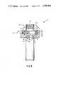
- FIG. 3illustrates a partial cross-section side view of the entire pump and motor assembly
- FIG. 4illustrates a top view of the pump in the tube loading mode of operation
- FIG. 5illustrates a perspective view of the medical solution filter system
- FIG. 6illustrates a top view of the medical solution filter system
- FIG. 7illustrates a top cutaway view of the medical solution filter system
- FIG. 8illustrates a cross-sectional side view of the medical solution filter system taken along line 8--8 of FIG. 5, with particular reference to medical solution flow;
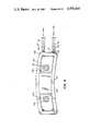
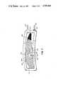
- FIG. 9illustrates in perspective a view of the IV medicine bag housing and attached electromechanical housing with the cover detached;
- FIG. 10illustrates an exploded view of the medicine bag housing and the electromechanical housing
- FIG. 11illustrates a cutaway top view of the medicine bag housing and attached electromechanical housing.
- FIG. 1illustrates an exploded perspective view of a peristalic medicine pump 10 showing a pump housing 12, pump rotor 14, sealed geared motor 16, loading tool 18, and all associated members to be herein described.
- the pump housing 12includes upper and lower shoulder rings 20 and 22, respectively; tube groove 24 between upper and lower shoulder rings 20 and 22; input tube slot 26; output tube slot 28; plastic pump tube 30 with inlet end 32 and outlet end 34, which pass through input and output hose slots 26 and 28 and ride partially within and juxtaposed to tube groove 24; a rotor cavity 36; bearing hole 38 and bearing 40; motor head recess 42; recessed motor mounting holes 44, 46 and 48; and microswitch actuator port 50.
- the clockwise rotation of the pump rotor 14mounts within the pump housing 12 and includes the rotor body 52, plunger slots 54, 56 and 58, which are offset at an angle to the radii of the rotor body 52 for friction minimizing.
- Plungers 60, 62, and 64, bearing plunger rollers 66, 68, and 70, and associated pinsmount in recesses within the ends of plungers 60, 62, and 64; springs 76, 78, and 80, push outwardly on plungers 60, 62, and 64; plunger spring containment holes 82, 84, and 86 and slot end spring containment holes 88, 90, and 92, as shown in FIG. 2, shaft hole 94 and clevis pin shelf 96.
- Bottom cover 98secures with machine screws from the bottom side into the bottom threaded holes 100, 102, and 104 within rotor body 52.
- the plungers 60-64 and the plunger rollers 66-70push outwardly, engaging and flattening the plastic tube 30 within the tube groove 24.
- fluidis moved clockwise between the portions of the tube flattened by the rollers being drawn in through inlet end 32 and expelled through outlet end 34.
- the circular shoulder 106 of sealed clockwise rotation geared electric low current drawn motor 16fits and secures within the motor recess 42 of the pump housing 12 with machine screws, not shown, through the recessed motor mounting holes 44-48 into the motor mounting holes 108, 110, and 112 correspondingly.
- Set pin 114secures the dual radius drive shaft 116 to the motor shaft.
- Bearing shaft 118, and element of the dual radius drive shaft 116engages frictionally within the bearing 40 of the pump housing, while the rotor shaft 120, also of dual radii drive shaft 116, engages within the shaft hole 94 of pump rotor.
- Clevis pin 122mounts in clevis hole 124, and clevis pin shelf 96 insuring movement of the pump rotor 14 in a clockwise motion.
- Loading tool 18includes a knurled actuating knob 126, top cover 128, tube feed bottom radiused fingers 130, 132, and 134.
- Machine screwspass through holes 136, 138, and 140 and engage the top threads of holes 100, 102, and 104 in rotary body 52 to secure the plungers 60, 62, and 64 within their respective slots 54, 56, and 58.
- FIG. 2illustrates a top view of the pump rotor assembly nested within the pump housing, where all numerals correspond to those elements previously described. Particular note is made of the uniquely mounted plungers 60-64 which are mounted in the rotor body 52 at an angle to the radius of the pump rotor body 52 in the direction of the pumping action and rotor motorization, minimizing friction between the rotor and the plungers which allows for a very low power operation and for high infusion rates.
- Tube groove 24 and shoulder rings 20 and 22provide guidance for the plunger rollers 66, 68, and 70, as illustrated in this figure, and provide for capture of the plastic pump tube 30 during pumping action as seen in FIG. 3.
- Springs 54, 56, and 58provide spring loading for the plungers to accommodate variances of the pump segment or tubing.
- FIG. 3illustrates a partial cross-section side view of the pump 10 where all numerals correspond to those elements previously described.
- plastic tube 30contained within tube groove 24 and upper and lower shoulder rings 20 and 22 being compressed by the resultant action of the spring 80 upon plunger 64 and plunger roller 70 during the pumping action.
- a microswitch actuating port 50allows for the roller 66-70 to actuate a microswitch probe for speed sensing and volume sensing or control of the motor and pump speed by electronic circuit board 286 of FIG. 9, and thus, a predetermined amount or dosage of medicine in a timely and controlled manner.
- FIG. 4illustrates a top view of the pump in the loading mode of operation, which is in progress.
- Tube 30, a tube of sufficient length,is pressed downwardly into the input tube slot 26.
- a tube loading finger 130radiused on the bottom corners, originally traversed in a clockwise direction, the area adjacent and to the right of tube slot 26, as the knurled manual actuating knob 126 was turned.
- the loader finger 130passed the tube 30, which then had a portion of it pressed into the tube slot 26 and the remainder sticking upwardly to the right of the slot, as shown in dashed lines, it pushed the tube downwardly into the tube groove 24 and continued to depress the tube 30 downwardly to its shown position in FIG. 4.
- the tube 30is then simply pressed with a finger or tool into the slot 28, completing the tube loading cycle.
- the loading fingers 130-134act additionally to maintain the tube within the proper area when pump is inverted and gravity attempts to cause the tubing to fall out of tube groove 24.
- FIG. 5illustrates a perspective overall view of the medical solution filter system 200.
- the filter 200includes upper curved filter member 202 and a lower four sided curved filter member 204, a hollow spike 206 with an IV medicine bag puncturing the tip 208, a filter inlet orifice 210 and an upper spike orifice 212.
- the spike 206secures into a hole 214 in the lower filter member 204, below an orifice top ring surface 216 as illustrated in FIG. 8.
- Ribs 218a-218nintegral with the upper surface of the lower filter body member, position longitudinally with a slight curvature conforming to that of the general filter body outline and extend almost to the ends of the cavity end walls 222 and 224, and form longitudinally valleys or gooves 219a-219n with the exception of annular groove area 226 surrounding the orifice top ring 216.
- a filter screen mesh 228positions on the ribs 218a-218n and over groove area 219a-219n and annular area 226.
- a hole 230 in the mesh filter screen 228corresponding to the size of the orifice top ring 216, fits down and over the orifice top ring 216 within the cavity 220.
- the upper filter body member 202including air elimination ports 232 and 234 and hydrophobic filters 236 and 238, secure with a bonded joint 240 to the filter body lower member 204, forming the cavity 220.
- a fluted filter outlet orifice 242having a commonalty joined with valleys 219a-219n and annular valley area 226 at the right rear end of the lower curved filter member body 204, support an end 248 of the peristaltic pump tube 30.
- the other end 248 of the peristalic pump tube 30secures to the fluted pump outlet orifice 250, which is plumbed in common only with the vertical fluted orifice 252.
- Tube 254conveys filtered medical solution from the pump tube 30 which fits in the tube slots 26 and 28 of the medicine pump 10 to the recipient patient.
- Alignment pins 256 and 258align the entire medical solution filter system 200 to the medicine pump 10 via a common housing or mounting member, not shown, for purposes of proper alignment of the pump 30 within the pump housing 12 of the medicine pump 10.
- FIG. 6illustrates a top view of the medical solution filter system. Particularly shown is the placement of the hydrophobic filters 236 and 238 with respect to the air elimination ports 232 and 234.
- FIG. 7illustrates a cutaway top view of the medical solution filter showing the ribs 218a-218n, valleys 219a-219n, the upper orifice hole 212, the annular groove and the overyling mesh screen filter 228.
- FIG. 8illustrates a cross-sectional longitudinal side view of the medical filter system 200 taken along line 8--8 of FIG. 5. Particularly shown are the medical solution and air flow paths. Fluid from the IV bag passes through the filter inlet orifice 210, through the upper spike orifice 212, laterally through the cavity 220, through the mesh screen filter 228, through and along valleys 219a-219n and annular area 226, through the filter outlet orifice 242 to pump 10 described previously. Any air in the cavity 220 is expelled through hydrophobic filters 236 and 238 through air elimination ports 232 and 234, respectively.
- FIG. 9illustrates a perspective view of the detachable recangular like medicine bag housing 350a-350b and attached electromechanical housing 352 with a geometrically configured cover 354 detached.
- the peristalic pump 10 and the filter 200both secure onto an alignment bracket 356 to insure proper spacing and placement between the peristalic pump 10, the filter 200 and the low durometer tube 30.
- Bracket 356, pump 10 and filter 200all secure to the electromechanical housing 352.
- the medicine bag 360 and its container 350a-350ncan be varying in dimension whether larger or smaller but still remain compatible for mating and attachment to the electromechanical housing 352 and its associated components.
- a cover 354 with a view port 355 and an exit tube slot 357fits and secures over and about the top portions of the combined medicine bag housing 350a and 350b and electromechanical housing 352.
- a belt clip 364secures on medicine bag housing 350b for convenient carriage upon the uses belt.
- FIG. 10illustrates an exploded view of the medicine bag housing 350a and 350b, and the electromechanical housing 352 and their associated components.
- Medicine bag housing 350ahas an outer contoured surface 366 and medicine bag housing 350b has an inner contoured surface 368 to conform to the general shape of the users hip.
- a hinge 351connects housing members 350a and 350b.
- Inner bag housing 358fits within housing 350a and 350b and has 4 slots 370a-370d in its vertical sides and a rectangular probe cutout 371 positioned on its upper surface for accommodation of the medicine bag puncture spike 206.
- IV medicine bag 360positions within the confines of the slotted contoured inner housing 358 and spring plate 362 with tabs 372a-372d engaged within slots 370a-370d respectively.
- a plurality of leaf springs 470a ⁇ 470nposition on a back surface of the spring plate 362 to apply pressure against the medicine bag 360 to provide a positive pressure of the infusate to the filter 200 and to the peristalic pump 10 when the medicine bag housing 350a is swung closed thus engaging against springs 470a-470n.
- a rectangular cutout 373positions on the upper surface of medicine bag housing 350b for accommodation of the medicine bag puncturing spike 206.
- Two quick connect fasteners 376 and 378mount on the geometrically configured electromechanical housing 352 to provide for rapid securing in configured holes 380 and 382 shown in dashed lines on the outer medicine bag housing member 350b.
- the motor 16 of the peristalic pump 10positions and aligns in a hole 390 in geometrically configured bracket 356 and subseuquently in hole 388 in the electromechanical housing 352.
- Bracket 356also includes a battery compartment cover 392, two filter alignment holes 396 and 398 and a speed sensing microswitch 394 which engages within the switch actuate hole 50 inpump housing 12 to be activated by contact by plunger rollers 66, 68, and 70 during their rotation within the pump housing 12.
- Alignment pins 256 and 258 on the filter 200engage within alignment holes 396 and 398 respectively within bracket 356 assuring proper alignment and spacing between the filter 200 and the peristalic pump 10 and also proper alignment of the low durometer tubeing 30 over and subsequently within tube groove 24 in pump housing 12.
- Geometrically configured cover 354including pump viewing port 355 and exit tube slot 357 positions over the combination of the electromechanical housing 352 and the variable size detachable medicine bag housing 350a and 350b and their associated described component members.
- the spike 206 in the filter 200punctures an outlet port 300 in the IV medicine bag 360 providing in conjunction with spring plate 362 pressure and infusate supply under positive pressure to the filter 200 and the inlet end 32 of low durometer tube 30 of the peristalic pump 10.
- FIG. 11illustrates a top cutaway view of the medicine bag housing 350a and 350b as attached to the electromechaincal housing 352.
- Springs 470a-470n on spring plate 362apply force between medicine bag casing 350a and the spring plate 362 and against IV medicine bag 360 to provide infusate under positive pressure to the filter 200.
- Tabs 372a-372d on spring plate 362engage within slots 370a and 370b in the inner housing 358 to allow for spring plate 362 movement and alignment with and aginst the IV medicine bag 360.
- Quick change connectors 376 and 378engage within holes 380 and 382 in medicine bag housing 350b coupling the variable size medicine bag housing 350a and 350b and its internal components to the electromechanical housing 352 including peristalic pump 10 and filter 200.
- FIG. 4best illustrates the mode of operation for the filtered low power peristaltic pump 10, the present invention in conjunction with FIGS. 4, 7 and 8 and other attendant FIGS.
- the medical solution filter system 200is positioned next to and adjacent to the peristaltic pump 10 with the plastic pump loop 30, as illustrated in FIG. 5 placed generally above the pump 10 as depicted partially in dashed lines in FIG. 4.
- the inlet portion 32 of the plastic pump tube 30is placed within the rear tube slot 26.
- Knurled actuating knob 126is rotated manually in a clockwise direction turning the top cover 128 including radii tube fingers 130-134 to provide downward loading action against pump tube 30 by approximately positioned fingers 130-134 to maneuver the pump tube 30 into the inner annular tube groove 24 in pump housing 12.
- FIG. 1is rotated manually in a clockwise direction turning the top cover 128 including radii tube fingers 130-134 to provide downward loading action against pump tube 30 by approximately positioned fingers 130-134 to maneuver the pump tube 30 into the inner annular tube groove 24 in pump housing
- FIG. 4illustrates tube feed finger 130 depressing the plastic pump tube 30 into annular tube groove 24.
- Manual rotation of knurled knob 126continues until the outlet end 34 of tube 30 is in a position to be manually inserted into slot 28. At this point the tube 30 is fully loaded into the pump 10 and is subsequently held in place by overhead fingers 130-134, annular groove 24 and by action of the spring loaded plunger rollers 66-70 forcing the tube into annular tube goove 24.
- Sealed gear motor 16provides rotary propulsion to turn the pump rotor 14, loading tool assembly 18 and associated component members. Plunger rollers 66-70 engage and ride within annular groove 24 when not actually engaged against pump tubing 30 as illustrated in FIG. 2.
- Spring loaded plungers 60-64 with plunger rollers 66-70are oriented at an angle in the direction of rotation of the pump rotor 14 approximately 30° to the radii of the pump rotor 14 which greatly reduces the lateral forces that would occur between the plunger surfaces and the plunger slots 54-58 should the plunger and slots not be angularly mounted with respect to the radii of the pump rotor 14.
- As the rollered plungers 60-64 rotate in a clockwise fashion medical solution in the low durometer PVC tubing 30is occluded at two points trapping and pumping the medical solution obtained in the tubing 30 between paired roller ends 68 and 70 or other sets of roller ends illustrated in FIG. 4.
Landscapes
- Engineering & Computer Science (AREA)
- Mechanical Engineering (AREA)
- General Engineering & Computer Science (AREA)
- Infusion, Injection, And Reservoir Apparatuses (AREA)
- Reciprocating Pumps (AREA)
Abstract
Description
Claims (1)
Priority Applications (1)
| Application Number | Priority Date | Filing Date | Title |
|---|---|---|---|
| US06/861,366US4705464A (en) | 1986-05-09 | 1986-05-09 | Medicine pump |
Applications Claiming Priority (1)
| Application Number | Priority Date | Filing Date | Title |
|---|---|---|---|
| US06/861,366US4705464A (en) | 1986-05-09 | 1986-05-09 | Medicine pump |
Publications (1)
| Publication Number | Publication Date |
|---|---|
| US4705464Atrue US4705464A (en) | 1987-11-10 |
Family
ID=25335600
Family Applications (1)
| Application Number | Title | Priority Date | Filing Date |
|---|---|---|---|
| US06/861,366Expired - Fee RelatedUS4705464A (en) | 1986-05-09 | 1986-05-09 | Medicine pump |
Country Status (1)
| Country | Link |
|---|---|
| US (1) | US4705464A (en) |
Cited By (61)
| Publication number | Priority date | Publication date | Assignee | Title |
|---|---|---|---|---|
| US4904168A (en)* | 1988-12-28 | 1990-02-27 | United Sonics, Inc. | Cassette assembly for ophthalmic surgery system |
| US4950136A (en)* | 1989-08-14 | 1990-08-21 | Hydro Systems Company | Peristaltic pump |
| US5013453A (en) | 1983-03-21 | 1991-05-07 | Union Oil Company Of California | Method for removing heavy metals from aqueous solutions by coprecipitation |
| US5024586A (en)* | 1990-03-13 | 1991-06-18 | Samuel Meiri | Accurate peristaltic pump for non elastic tubing |
| EP0470333A1 (en)* | 1990-08-07 | 1992-02-12 | Katsuo Hosokawa | flexible tube for Volume displacement machine |
| US5094820A (en)* | 1990-04-26 | 1992-03-10 | Minnesota Mining And Manufacturing Company | Pump and calibration system |
| US5263831A (en)* | 1992-02-19 | 1993-11-23 | Cobe Laboratories, Inc. | Peristaltic pump |
| US5354186A (en)* | 1993-08-12 | 1994-10-11 | The Board Of Regents Of The University Of Michigan | Machine balancer with peristaltic fluid pump |
| US5387088A (en)* | 1994-01-18 | 1995-02-07 | Haemonetics Corporation | Peristaltic pump tube loading assembly |
| US5427509A (en)* | 1993-12-22 | 1995-06-27 | Baxter International Inc. | Peristaltic pump tube cassette with angle pump tube connectors |
| US5445506A (en)* | 1993-12-22 | 1995-08-29 | Baxter International Inc. | Self loading peristaltic pump tube cassette |
| US5447417A (en)* | 1993-08-31 | 1995-09-05 | Valleylab Inc. | Self-adjusting pump head and safety manifold cartridge for a peristaltic pump |
| WO1995031643A1 (en)* | 1994-05-11 | 1995-11-23 | Debiotech S.A. | Peristaltic pump device |
| US5480294A (en)* | 1993-12-22 | 1996-01-02 | Baxter International Inc. | Peristaltic pump module having jaws for gripping a peristaltic pump tube cassett |
| US5484239A (en)* | 1993-12-22 | 1996-01-16 | Baxter International Inc. | Peristaltic pump and valve assembly for fluid processing systems |
| US5549458A (en)* | 1994-07-01 | 1996-08-27 | Baxter International Inc. | Peristaltic pump with quick release rotor head assembly |
| WO1997010863A1 (en)* | 1995-09-21 | 1997-03-27 | Abbott Laboratories | Fluid delivery set |
| US5711654A (en)* | 1995-06-07 | 1998-01-27 | Baxter International Inc. | Peristaltic pump with rotor position sensing employing a reflective object sensor |
| US5746708A (en)* | 1993-12-22 | 1998-05-05 | Baxter International Inc. | Peristaltic pump tube holder with pump tube shield and cover |
| US5800383A (en)* | 1996-07-17 | 1998-09-01 | Aquarius Medical Corporation | Fluid management system for arthroscopic surgery |
| US5830180A (en)* | 1996-07-17 | 1998-11-03 | Aquarius Medical Corporation | Fluid management system for arthroscopic surgery |
| US5906598A (en)* | 1993-12-22 | 1999-05-25 | Baxter International Inc. | Self-priming drip chamber with extended field of vision |
| US6024720A (en)* | 1995-07-18 | 2000-02-15 | Aquarius Medical Corporation | Fluid management system for arthroscopic surgery |
| US6109895A (en)* | 1996-09-10 | 2000-08-29 | Conseil-Ray S.A. | Portable peristaltic pump |
| US6290469B1 (en)* | 1997-05-13 | 2001-09-18 | Frank E. Archibald | Hand held, self-powered pump |
| US6494693B1 (en)* | 2000-10-23 | 2002-12-17 | Cole-Parmer Instrument Company | Peristatic pump |
| US20030216714A1 (en)* | 2002-04-30 | 2003-11-20 | Gill Steven Streatfield | Pump |
| WO2004005717A1 (en)* | 2002-07-09 | 2004-01-15 | Gambro Lundia Ab | A support element for an extracorporeal fluid transport line |
| US20040131487A1 (en)* | 2002-10-02 | 2004-07-08 | Hideaki Ito | Tube type pumping apparatus |
| US20050127104A1 (en)* | 2003-12-16 | 2005-06-16 | Tu Ming T. | Liquid rationing device |
| US20070299408A1 (en)* | 2006-03-16 | 2007-12-27 | Seattle Medical Technologies | Infusion device pump |
| US20080021364A1 (en)* | 2006-07-17 | 2008-01-24 | Industrial Technology Research Institute | Fluidic device |
| US20080035499A1 (en)* | 2006-07-17 | 2008-02-14 | Industrial Technology Research Institute | Fluidic device |
| US20080047608A1 (en)* | 2006-07-17 | 2008-02-28 | Industrial Technology Research Institute | Fluidic device |
| US20080097317A1 (en)* | 2006-08-25 | 2008-04-24 | Jeffery Alholm | Infusion pump |
| US20080188789A1 (en)* | 2004-09-06 | 2008-08-07 | Francesca Galavotti | Peristaltic Pump Tube |
| US20110106027A1 (en)* | 2009-11-05 | 2011-05-05 | Tyco Healthcare Group Lp | Chemically Coated Screen for Use with Hydrophobic Filters |
| WO2011083892A3 (en)* | 2010-01-06 | 2011-09-01 | 메인텍 주식회사 | Cylinder pump |
| US8827987B2 (en) | 2010-02-12 | 2014-09-09 | Renishaw (Ireland) Limited | Percutaneous drug delivery apparatus |
| US20150037168A1 (en)* | 2012-03-02 | 2015-02-05 | Tecres S.P.A | Universal infusion device for liquid medicines and the like, and method for controlling the erogation of such liquid medicine and the like |
| US9140251B2 (en) | 2011-01-10 | 2015-09-22 | Fresenius Medical Care Holdings, Inc. | Peristaltic pump arrangement and pump rollers |
| US20160061198A1 (en)* | 2013-05-17 | 2016-03-03 | Nidec Copal Electronics Corporation | Infusion pump cassette and infusion pump |
| US20160123317A1 (en)* | 2013-06-06 | 2016-05-05 | Bausch + Ströbel Maschinenfabrik Ilshofen GmbH + Co. KG | Peristaltic pump having reduced pulsation and use of the peristaltic pump |
| US20160158437A1 (en)* | 2014-09-18 | 2016-06-09 | Deka Products Limited Partnership | Apparatus and Method for Infusing Fluid Through a Tube by Appropriately Heating the Tube |
| US9662484B2 (en) | 2012-10-02 | 2017-05-30 | Renishaw Plc | Neurosurgical device and method |
| US20170268496A1 (en)* | 2016-03-21 | 2017-09-21 | John McIntyre | Peristaltic pump |
| US9999712B2 (en) | 2014-09-19 | 2018-06-19 | Johnson Electric S.A. | Medical peristaltic pump |
| EP3483442A1 (en)* | 2017-11-10 | 2019-05-15 | Takasago Electric, Inc. | Peristaltic pump device |
| US10751520B2 (en) | 2006-11-23 | 2020-08-25 | Renishaw (Ireland) Limited | Neurological apparatus comprising a percutaneous access device |
| US11024409B2 (en) | 2011-12-21 | 2021-06-01 | Deka Products Limited Partnership | Peristaltic pump |
| GB2591476A (en)* | 2020-01-29 | 2021-08-04 | Aspen Pumps Ltd | Peristaltic pump |
| US20210239108A1 (en)* | 2020-01-31 | 2021-08-05 | Surpass Industry Co., Ltd. | Tube pump |
| US11295846B2 (en) | 2011-12-21 | 2022-04-05 | Deka Products Limited Partnership | System, method, and apparatus for infusing fluid |
| US11511038B2 (en) | 2011-12-21 | 2022-11-29 | Deka Products Limited Partnership | Apparatus for infusing fluid |
| US11542937B2 (en) | 2019-02-15 | 2023-01-03 | Surpass Industry Co., Ltd. | Tube pump system and method for controlling the tube pump system |
| CN116357401A (en)* | 2023-04-12 | 2023-06-30 | 上海大学 | air motor |
| US11707615B2 (en) | 2018-08-16 | 2023-07-25 | Deka Products Limited Partnership | Medical pump |
| US11939972B2 (en) | 2020-05-06 | 2024-03-26 | Blue-White Industries, Ltd. | Rotor assembly with removable rollers |
| US12018670B2 (en) | 2020-05-26 | 2024-06-25 | Surpass Industry Co., Ltd. | Tube pump system |
| US12025117B2 (en) | 2020-05-26 | 2024-07-02 | Surpass Industry Co., Ltd. | Tube holding member and tube pump |
| GB2627159A (en)* | 2020-05-06 | 2024-08-14 | Blue White Ind Ltd | Rotor assembly with removable rollers |
Citations (8)
| Publication number | Priority date | Publication date | Assignee | Title |
|---|---|---|---|---|
| GB628785A (en)* | 1947-10-16 | 1949-09-05 | Denis Withinshaw Rowley | Improvements in flexible tube pumps |
| US3137242A (en)* | 1962-01-22 | 1964-06-16 | Hahn George William | Infusion pump |
| US3756752A (en)* | 1971-12-20 | 1973-09-04 | G Stenner | Peristaltic pump |
| US4185948A (en)* | 1977-11-30 | 1980-01-29 | Maguire Stephen B | Peristaltic pump construction |
| US4210138A (en)* | 1977-12-02 | 1980-07-01 | Baxter Travenol Laboratories, Inc. | Metering apparatus for a fluid infusion system with flow control station |
| US4500269A (en)* | 1983-11-30 | 1985-02-19 | Cormed, Inc. | Integral tube-loading assembly for peristaltic pump |
| US4527323A (en)* | 1983-10-11 | 1985-07-09 | Cole-Parmer Instrument Company | Tubing loading key |
| US4606710A (en)* | 1985-10-09 | 1986-08-19 | Maguire Stephen B | Peristaltic pump |
- 1986
- 1986-05-09USUS06/861,366patent/US4705464A/ennot_activeExpired - Fee Related
Patent Citations (8)
| Publication number | Priority date | Publication date | Assignee | Title |
|---|---|---|---|---|
| GB628785A (en)* | 1947-10-16 | 1949-09-05 | Denis Withinshaw Rowley | Improvements in flexible tube pumps |
| US3137242A (en)* | 1962-01-22 | 1964-06-16 | Hahn George William | Infusion pump |
| US3756752A (en)* | 1971-12-20 | 1973-09-04 | G Stenner | Peristaltic pump |
| US4185948A (en)* | 1977-11-30 | 1980-01-29 | Maguire Stephen B | Peristaltic pump construction |
| US4210138A (en)* | 1977-12-02 | 1980-07-01 | Baxter Travenol Laboratories, Inc. | Metering apparatus for a fluid infusion system with flow control station |
| US4527323A (en)* | 1983-10-11 | 1985-07-09 | Cole-Parmer Instrument Company | Tubing loading key |
| US4500269A (en)* | 1983-11-30 | 1985-02-19 | Cormed, Inc. | Integral tube-loading assembly for peristaltic pump |
| US4606710A (en)* | 1985-10-09 | 1986-08-19 | Maguire Stephen B | Peristaltic pump |
Cited By (117)
| Publication number | Priority date | Publication date | Assignee | Title |
|---|---|---|---|---|
| US5013453A (en) | 1983-03-21 | 1991-05-07 | Union Oil Company Of California | Method for removing heavy metals from aqueous solutions by coprecipitation |
| US4904168A (en)* | 1988-12-28 | 1990-02-27 | United Sonics, Inc. | Cassette assembly for ophthalmic surgery system |
| US4950136A (en)* | 1989-08-14 | 1990-08-21 | Hydro Systems Company | Peristaltic pump |
| US5024586A (en)* | 1990-03-13 | 1991-06-18 | Samuel Meiri | Accurate peristaltic pump for non elastic tubing |
| US5094820A (en)* | 1990-04-26 | 1992-03-10 | Minnesota Mining And Manufacturing Company | Pump and calibration system |
| EP0470333A1 (en)* | 1990-08-07 | 1992-02-12 | Katsuo Hosokawa | flexible tube for Volume displacement machine |
| US5263831A (en)* | 1992-02-19 | 1993-11-23 | Cobe Laboratories, Inc. | Peristaltic pump |
| US5354186A (en)* | 1993-08-12 | 1994-10-11 | The Board Of Regents Of The University Of Michigan | Machine balancer with peristaltic fluid pump |
| WO1995005268A1 (en)* | 1993-08-12 | 1995-02-23 | The Board Of Regents Of The University Of Michigan | Machine balancer with peristaltic fluid pump |
| US5447417A (en)* | 1993-08-31 | 1995-09-05 | Valleylab Inc. | Self-adjusting pump head and safety manifold cartridge for a peristaltic pump |
| US5445506A (en)* | 1993-12-22 | 1995-08-29 | Baxter International Inc. | Self loading peristaltic pump tube cassette |
| US5746708A (en)* | 1993-12-22 | 1998-05-05 | Baxter International Inc. | Peristaltic pump tube holder with pump tube shield and cover |
| US5427509A (en)* | 1993-12-22 | 1995-06-27 | Baxter International Inc. | Peristaltic pump tube cassette with angle pump tube connectors |
| US5480294A (en)* | 1993-12-22 | 1996-01-02 | Baxter International Inc. | Peristaltic pump module having jaws for gripping a peristaltic pump tube cassett |
| US5484239A (en)* | 1993-12-22 | 1996-01-16 | Baxter International Inc. | Peristaltic pump and valve assembly for fluid processing systems |
| US5906598A (en)* | 1993-12-22 | 1999-05-25 | Baxter International Inc. | Self-priming drip chamber with extended field of vision |
| US5868696A (en)* | 1993-12-22 | 1999-02-09 | Baxter International Inc. | Peristaltic pump tube holder with pump tube shield and cover |
| EP0663529A1 (en)* | 1994-01-18 | 1995-07-19 | Haemonetics Corporation | Peristaltic pump tube loading assembly |
| US5387088A (en)* | 1994-01-18 | 1995-02-07 | Haemonetics Corporation | Peristaltic pump tube loading assembly |
| WO1995031643A1 (en)* | 1994-05-11 | 1995-11-23 | Debiotech S.A. | Peristaltic pump device |
| AU687207B2 (en)* | 1994-05-11 | 1998-02-19 | Debiotech S.A. | Peristaltic pump device |
| US5741125A (en)* | 1994-05-11 | 1998-04-21 | Debiotech S.A. | Peristaltic pump device having an insert cassette of reduced complexity |
| US5549458A (en)* | 1994-07-01 | 1996-08-27 | Baxter International Inc. | Peristaltic pump with quick release rotor head assembly |
| US5711654A (en)* | 1995-06-07 | 1998-01-27 | Baxter International Inc. | Peristaltic pump with rotor position sensing employing a reflective object sensor |
| US6024720A (en)* | 1995-07-18 | 2000-02-15 | Aquarius Medical Corporation | Fluid management system for arthroscopic surgery |
| US5681294A (en)* | 1995-09-21 | 1997-10-28 | Abbott Laboratories | Fluid delivery set |
| WO1997010863A1 (en)* | 1995-09-21 | 1997-03-27 | Abbott Laboratories | Fluid delivery set |
| AU712488B2 (en)* | 1995-09-21 | 1999-11-11 | Abbott Laboratories | Fluid delivery set |
| US5800383A (en)* | 1996-07-17 | 1998-09-01 | Aquarius Medical Corporation | Fluid management system for arthroscopic surgery |
| US5830180A (en)* | 1996-07-17 | 1998-11-03 | Aquarius Medical Corporation | Fluid management system for arthroscopic surgery |
| US6109895A (en)* | 1996-09-10 | 2000-08-29 | Conseil-Ray S.A. | Portable peristaltic pump |
| US6290469B1 (en)* | 1997-05-13 | 2001-09-18 | Frank E. Archibald | Hand held, self-powered pump |
| US6494693B1 (en)* | 2000-10-23 | 2002-12-17 | Cole-Parmer Instrument Company | Peristatic pump |
| US7341577B2 (en)* | 2002-04-30 | 2008-03-11 | Renishaw Plc | Implantable drug delivery pump |
| US20030216714A1 (en)* | 2002-04-30 | 2003-11-20 | Gill Steven Streatfield | Pump |
| WO2004005717A1 (en)* | 2002-07-09 | 2004-01-15 | Gambro Lundia Ab | A support element for an extracorporeal fluid transport line |
| US20050245871A1 (en)* | 2002-07-09 | 2005-11-03 | Annalisa Delnevo | Support element for an extracorporeal fluid transport line |
| US7422565B2 (en) | 2002-07-09 | 2008-09-09 | Gambro Lundia Ab | Support element for an extracorporeal fluid transport line |
| US20040131487A1 (en)* | 2002-10-02 | 2004-07-08 | Hideaki Ito | Tube type pumping apparatus |
| US7252485B2 (en)* | 2002-10-02 | 2007-08-07 | Nidec Sankyo Corporation | Tube type pumping apparatus |
| US20050127104A1 (en)* | 2003-12-16 | 2005-06-16 | Tu Ming T. | Liquid rationing device |
| US6948638B2 (en)* | 2003-12-16 | 2005-09-27 | Kuei-Tang Chou | Liquid rationing device |
| US20080188789A1 (en)* | 2004-09-06 | 2008-08-07 | Francesca Galavotti | Peristaltic Pump Tube |
| US10563646B2 (en)* | 2004-09-06 | 2020-02-18 | Gambro Lundia Ab | Peristaltic pump tube |
| US12025115B2 (en) | 2004-09-06 | 2024-07-02 | Gambro Lundia Ab | Peristaltic pump tube |
| US20200182232A1 (en)* | 2004-09-06 | 2020-06-11 | Gambro Lundia Ab | Peristaltic pump tube |
| US11060516B2 (en) | 2004-09-06 | 2021-07-13 | Gambro Lundia Ab | Peristaltic pump tube |
| WO2007108969A3 (en)* | 2006-03-16 | 2008-01-03 | Seattle Medical Technologies I | Infusion device with dosage dial control |
| US20070299399A1 (en)* | 2006-03-16 | 2007-12-27 | Seattle Medical Technologies | Infusion device with dosage dial control |
| US20070299398A1 (en)* | 2006-03-16 | 2007-12-27 | Seattle Medical Technologies | Infusion device capable of providing multiple liquid medicaments |
| US20070299401A1 (en)* | 2006-03-16 | 2007-12-27 | Seattle Medical Technologies | Infusion device with piston pump |
| US8758308B2 (en) | 2006-03-16 | 2014-06-24 | Calibra Medical, Inc. | Infusion device pump |
| US20070299400A1 (en)* | 2006-03-16 | 2007-12-27 | Seattle Medical Technologies | Infusion device with dome pump |
| US20070299408A1 (en)* | 2006-03-16 | 2007-12-27 | Seattle Medical Technologies | Infusion device pump |
| US8114064B2 (en)* | 2006-03-16 | 2012-02-14 | Calibra Medical, Inc. | Infusion device with piston pump |
| US20070299397A1 (en)* | 2006-03-16 | 2007-12-27 | Seattle Medical Technologies | Infusion device with pressurizable liquid medicament chamber |
| US20080021364A1 (en)* | 2006-07-17 | 2008-01-24 | Industrial Technology Research Institute | Fluidic device |
| US7959876B2 (en) | 2006-07-17 | 2011-06-14 | Industrial Technology Research Institute | Fluidic device |
| US7794665B2 (en) | 2006-07-17 | 2010-09-14 | Industrial Technology Research Institute | Fluidic device |
| US20080047608A1 (en)* | 2006-07-17 | 2008-02-28 | Industrial Technology Research Institute | Fluidic device |
| US20080035499A1 (en)* | 2006-07-17 | 2008-02-14 | Industrial Technology Research Institute | Fluidic device |
| US20080097317A1 (en)* | 2006-08-25 | 2008-04-24 | Jeffery Alholm | Infusion pump |
| US10751520B2 (en) | 2006-11-23 | 2020-08-25 | Renishaw (Ireland) Limited | Neurological apparatus comprising a percutaneous access device |
| US11717663B2 (en) | 2006-11-23 | 2023-08-08 | Renishaw (Ireland) Limited | Neurological apparatus comprising a percutaneous access device |
| US20110106027A1 (en)* | 2009-11-05 | 2011-05-05 | Tyco Healthcare Group Lp | Chemically Coated Screen for Use with Hydrophobic Filters |
| US20130190705A1 (en)* | 2009-11-05 | 2013-07-25 | Tyco Healthcare Group Lp | Chemically Coated Screen for Use with Hydrophobic Filters |
| WO2011083892A3 (en)* | 2010-01-06 | 2011-09-01 | 메인텍 주식회사 | Cylinder pump |
| CN102711870B (en)* | 2010-01-06 | 2015-01-14 | 医疗革新技术有限公司 | Cylinder pump |
| CN102711870A (en)* | 2010-01-06 | 2012-10-03 | 医疗革新技术有限公司 | Cylinder pump |
| RU2529405C2 (en)* | 2010-01-06 | 2014-09-27 | Мейннтех Ко., Лтд. | Cylindrical pump |
| EP2522381A4 (en)* | 2010-01-06 | 2017-12-06 | Meinntech Co. Ltd. | Cylinder pump |
| AU2010340482B2 (en)* | 2010-01-06 | 2014-01-09 | Kun-Hyung Lee | Cylinder pump |
| US8529512B2 (en) | 2010-01-06 | 2013-09-10 | Meinntech Co., Ltd. | Cylinder pump |
| US11826536B2 (en) | 2010-02-12 | 2023-11-28 | Renishaw (Ireland) Limited | Percutaneous drug delivery apparatus |
| US10596362B2 (en) | 2010-02-12 | 2020-03-24 | Renishaw (Ireland) Limited | Percutaneous drug delivery apparatus |
| US8827987B2 (en) | 2010-02-12 | 2014-09-09 | Renishaw (Ireland) Limited | Percutaneous drug delivery apparatus |
| US10507316B2 (en) | 2010-02-12 | 2019-12-17 | Renishaw (Ireland) Limited | Implantable fluid router |
| US9140251B2 (en) | 2011-01-10 | 2015-09-22 | Fresenius Medical Care Holdings, Inc. | Peristaltic pump arrangement and pump rollers |
| US11024409B2 (en) | 2011-12-21 | 2021-06-01 | Deka Products Limited Partnership | Peristaltic pump |
| US11705233B2 (en) | 2011-12-21 | 2023-07-18 | Deka Products Limited Partnership | Peristaltic pump |
| US11511038B2 (en) | 2011-12-21 | 2022-11-29 | Deka Products Limited Partnership | Apparatus for infusing fluid |
| US11756662B2 (en) | 2011-12-21 | 2023-09-12 | Deka Products Limited Partnership | Peristaltic pump |
| US11373747B2 (en) | 2011-12-21 | 2022-06-28 | Deka Products Limited Partnership | Peristaltic pump |
| US12020798B2 (en) | 2011-12-21 | 2024-06-25 | Deka Products Limited Partnership | Peristaltic pump and related method |
| US11348674B2 (en) | 2011-12-21 | 2022-05-31 | Deka Products Limited Partnership | Peristaltic pump |
| US11295846B2 (en) | 2011-12-21 | 2022-04-05 | Deka Products Limited Partnership | System, method, and apparatus for infusing fluid |
| US11779703B2 (en) | 2011-12-21 | 2023-10-10 | Deka Products Limited Partnership | Apparatus for infusing fluid |
| US12002561B2 (en) | 2011-12-21 | 2024-06-04 | DEKA Research & Development Corp | System, method, and apparatus for infusing fluid |
| US20150037168A1 (en)* | 2012-03-02 | 2015-02-05 | Tecres S.P.A | Universal infusion device for liquid medicines and the like, and method for controlling the erogation of such liquid medicine and the like |
| US9662484B2 (en) | 2012-10-02 | 2017-05-30 | Renishaw Plc | Neurosurgical device and method |
| US20160061198A1 (en)* | 2013-05-17 | 2016-03-03 | Nidec Copal Electronics Corporation | Infusion pump cassette and infusion pump |
| US20160123317A1 (en)* | 2013-06-06 | 2016-05-05 | Bausch + Ströbel Maschinenfabrik Ilshofen GmbH + Co. KG | Peristaltic pump having reduced pulsation and use of the peristaltic pump |
| US10465673B2 (en)* | 2013-06-06 | 2019-11-05 | Bausch + Ströbel Maschinenfabrik Ilshofen GmbH + Co. KG | Peristaltic pump having reduced pulsation and use of the peristaltic pump |
| US20230364328A1 (en)* | 2014-09-18 | 2023-11-16 | Deka Products Limited Partnership | Apparatus and method for infusing fluid through a tube by appropriately heating the tube |
| US20160158437A1 (en)* | 2014-09-18 | 2016-06-09 | Deka Products Limited Partnership | Apparatus and Method for Infusing Fluid Through a Tube by Appropriately Heating the Tube |
| US10265463B2 (en)* | 2014-09-18 | 2019-04-23 | Deka Products Limited Partnership | Apparatus and method for infusing fluid through a tube by appropriately heating the tube |
| US20190298913A1 (en)* | 2014-09-18 | 2019-10-03 | Deka Products Limited Partnership | Apparatus and Method for Infusing Fluid Through a Tube by Appropriately Heating the Tube |
| US11672903B2 (en)* | 2014-09-18 | 2023-06-13 | Deka Products Limited Partnership | Apparatus and method for infusing fluid through a tube by appropriately heating the tube |
| US9999712B2 (en) | 2014-09-19 | 2018-06-19 | Johnson Electric S.A. | Medical peristaltic pump |
| US10151309B2 (en)* | 2016-03-21 | 2018-12-11 | John McIntyre | Peristaltic pump |
| US20170268496A1 (en)* | 2016-03-21 | 2017-09-21 | John McIntyre | Peristaltic pump |
| CN109763968A (en)* | 2017-11-10 | 2019-05-17 | 高砂电气工业株式会社 | Peristaltic-type pump arrangement |
| EP3483442A1 (en)* | 2017-11-10 | 2019-05-15 | Takasago Electric, Inc. | Peristaltic pump device |
| US11707615B2 (en) | 2018-08-16 | 2023-07-25 | Deka Products Limited Partnership | Medical pump |
| US12251532B2 (en) | 2018-08-16 | 2025-03-18 | Deka Products Limited Partnership | Medical pump |
| US11542937B2 (en) | 2019-02-15 | 2023-01-03 | Surpass Industry Co., Ltd. | Tube pump system and method for controlling the tube pump system |
| GB2591476B (en)* | 2020-01-29 | 2022-08-10 | Aspen Pumps Ltd | Peristaltic pump |
| GB2591476A (en)* | 2020-01-29 | 2021-08-04 | Aspen Pumps Ltd | Peristaltic pump |
| US20210239108A1 (en)* | 2020-01-31 | 2021-08-05 | Surpass Industry Co., Ltd. | Tube pump |
| US12221956B2 (en)* | 2020-01-31 | 2025-02-11 | Surpass Industry Co., Ltd. | Tube pump |
| US11939972B2 (en) | 2020-05-06 | 2024-03-26 | Blue-White Industries, Ltd. | Rotor assembly with removable rollers |
| GB2627159A (en)* | 2020-05-06 | 2024-08-14 | Blue White Ind Ltd | Rotor assembly with removable rollers |
| GB2595772B (en)* | 2020-05-06 | 2024-08-28 | Blue White Ind Ltd | Rotor assembly with removable rollers |
| GB2627159B (en)* | 2020-05-06 | 2025-02-12 | Blue White Ind Ltd | Rotor assembly with removable rollers |
| US12018670B2 (en) | 2020-05-26 | 2024-06-25 | Surpass Industry Co., Ltd. | Tube pump system |
| US12025117B2 (en) | 2020-05-26 | 2024-07-02 | Surpass Industry Co., Ltd. | Tube holding member and tube pump |
| CN116357401A (en)* | 2023-04-12 | 2023-06-30 | 上海大学 | air motor |
Similar Documents
| Publication | Publication Date | Title |
|---|---|---|
| US4705464A (en) | Medicine pump | |
| US9192713B2 (en) | Manually operable portable infusion device | |
| US8137314B2 (en) | Infusion medium delivery device and method with compressible or curved reservoir or conduit | |
| US4525164A (en) | Wearable medication infusion system with arcuated reservoir | |
| US10398831B2 (en) | Positive displacement pump | |
| US4846637A (en) | Infusion pump system and conduit therefor | |
| US8512288B2 (en) | Infusion medium delivery device and method with drive device for driving plunger in reservoir | |
| US4781548A (en) | Infusion pump system and conduit therefor | |
| US7128727B2 (en) | Components and methods for patient infusion device | |
| US7736344B2 (en) | Infusion medium delivery device and method with drive device for driving plunger in reservoir | |
| EP2185219B1 (en) | Portable infusion device provided with means for monitoring and controlling fluid delivery | |
| US7641649B2 (en) | Reservoir support and method for infusion device | |
| US4890984A (en) | Infusion pump system and conduit therefor | |
| EP2438957A1 (en) | Dispenser components and methods for patient infusion device | |
| US20080051711A1 (en) | Infusion medium delivery device and method with drive device for driving plunger in reservoir | |
| JP2002535554A (en) | Metered dose infusion pump and method | |
| EP0551416A1 (en) | DEVICE FOR DISPENSING LIQUID UNDER CONTROLLED PRESSURE. | |
| WO1988000841A1 (en) | Expansible chamber drug infuser system | |
| JPH11114061A (en) | Chemical liquid supplying instrument |
Legal Events
| Date | Code | Title | Description |
|---|---|---|---|
| AS | Assignment | Owner name:SURGIDEV CORPORATION GOLETA, CA. A CORP. OF CA. Free format text:ASSIGNMENT OF ASSIGNORS INTEREST.;ASSIGNOR:ARIMOND, TIMOTHY V.;REEL/FRAME:004592/0347 Effective date:19860506 | |
| AS | Assignment | Owner name:GRENDAHL, DENNIS T., 2070 SHORELINE DRIVE, ORONO, Free format text:ASSIGNMENT OF ASSIGNORS INTEREST.;ASSIGNOR:SURGIDEV CORPORATION, A CORP. OF CA;REEL/FRAME:004880/0010 Effective date:19880317 Owner name:GRENDAHL, DENNIS T.,MINNESOTA Free format text:ASSIGNMENT OF ASSIGNORS INTEREST;ASSIGNOR:SURGIDEV CORPORATION, A CORP. OF CA;REEL/FRAME:004880/0010 Effective date:19880317 | |
| FEPP | Fee payment procedure | Free format text:PAYOR NUMBER ASSIGNED (ORIGINAL EVENT CODE: ASPN); ENTITY STATUS OF PATENT OWNER: SMALL ENTITY | |
| REMI | Maintenance fee reminder mailed | ||
| FPAY | Fee payment | Year of fee payment:4 | |
| SULP | Surcharge for late payment | ||
| REMI | Maintenance fee reminder mailed | ||
| LAPS | Lapse for failure to pay maintenance fees | ||
| FP | Lapsed due to failure to pay maintenance fee | Effective date:19961115 | |
| STCH | Information on status: patent discontinuation | Free format text:PATENT EXPIRED DUE TO NONPAYMENT OF MAINTENANCE FEES UNDER 37 CFR 1.362 |