US4705352A - Fiber optic connector - Google Patents
Fiber optic connectorDownload PDFInfo
- Publication number
- US4705352A US4705352AUS06/818,576US81857685AUS4705352AUS 4705352 AUS4705352 AUS 4705352AUS 81857685 AUS81857685 AUS 81857685AUS 4705352 AUS4705352 AUS 4705352A
- Authority
- US
- United States
- Prior art keywords
- connector
- fiber optic
- fiber
- cable
- matching halves
- Prior art date
- Legal status (The legal status is an assumption and is not a legal conclusion. Google has not performed a legal analysis and makes no representation as to the accuracy of the status listed.)
- Expired - Lifetime
Links
Images

Classifications
- G—PHYSICS
- G02—OPTICS
- G02B—OPTICAL ELEMENTS, SYSTEMS OR APPARATUS
- G02B6/00—Light guides; Structural details of arrangements comprising light guides and other optical elements, e.g. couplings
- G02B6/24—Coupling light guides
- G02B6/36—Mechanical coupling means
- G02B6/38—Mechanical coupling means having fibre to fibre mating means
- G02B6/3807—Dismountable connectors, i.e. comprising plugs
- G02B6/3833—Details of mounting fibres in ferrules; Assembly methods; Manufacture
- G02B6/3855—Details of mounting fibres in ferrules; Assembly methods; Manufacture characterised by the method of anchoring or fixing the fibre within the ferrule
- G02B6/3858—Clamping, i.e. with only elastic deformation
- G—PHYSICS
- G02—OPTICS
- G02B—OPTICAL ELEMENTS, SYSTEMS OR APPARATUS
- G02B6/00—Light guides; Structural details of arrangements comprising light guides and other optical elements, e.g. couplings
- G02B6/24—Coupling light guides
- G02B6/36—Mechanical coupling means
- G02B6/38—Mechanical coupling means having fibre to fibre mating means
- G02B6/3807—Dismountable connectors, i.e. comprising plugs
- G02B6/3833—Details of mounting fibres in ferrules; Assembly methods; Manufacture
- G02B6/3834—Means for centering or aligning the light guide within the ferrule
- G02B6/3838—Means for centering or aligning the light guide within the ferrule using grooves for light guides
- G—PHYSICS
- G02—OPTICS
- G02B—OPTICAL ELEMENTS, SYSTEMS OR APPARATUS
- G02B6/00—Light guides; Structural details of arrangements comprising light guides and other optical elements, e.g. couplings
- G02B6/24—Coupling light guides
- G02B6/36—Mechanical coupling means
- G02B6/38—Mechanical coupling means having fibre to fibre mating means
- G02B6/3807—Dismountable connectors, i.e. comprising plugs
- G02B6/3833—Details of mounting fibres in ferrules; Assembly methods; Manufacture
- G02B6/3855—Details of mounting fibres in ferrules; Assembly methods; Manufacture characterised by the method of anchoring or fixing the fibre within the ferrule
- G02B6/3862—Details of mounting fibres in ferrules; Assembly methods; Manufacture characterised by the method of anchoring or fixing the fibre within the ferrule radially-compressed, longitudinally-split ferrules consisting of a pair of identical matching halves
- G—PHYSICS
- G02—OPTICS
- G02B—OPTICAL ELEMENTS, SYSTEMS OR APPARATUS
- G02B6/00—Light guides; Structural details of arrangements comprising light guides and other optical elements, e.g. couplings
- G02B6/24—Coupling light guides
- G02B6/36—Mechanical coupling means
- G02B6/38—Mechanical coupling means having fibre to fibre mating means
- G02B6/3807—Dismountable connectors, i.e. comprising plugs
- G02B6/3887—Anchoring optical cables to connector housings, e.g. strain relief features
- G02B6/3888—Protection from over-extension or over-compression
- G—PHYSICS
- G02—OPTICS
- G02B—OPTICAL ELEMENTS, SYSTEMS OR APPARATUS
- G02B6/00—Light guides; Structural details of arrangements comprising light guides and other optical elements, e.g. couplings
- G02B6/24—Coupling light guides
- G02B6/36—Mechanical coupling means
- G02B6/38—Mechanical coupling means having fibre to fibre mating means
- G02B6/3807—Dismountable connectors, i.e. comprising plugs
- G02B6/381—Dismountable connectors, i.e. comprising plugs of the ferrule type, e.g. fibre ends embedded in ferrules, connecting a pair of fibres
- G02B6/3826—Dismountable connectors, i.e. comprising plugs of the ferrule type, e.g. fibre ends embedded in ferrules, connecting a pair of fibres characterised by form or shape
- G02B6/3831—Dismountable connectors, i.e. comprising plugs of the ferrule type, e.g. fibre ends embedded in ferrules, connecting a pair of fibres characterised by form or shape comprising a keying element on the plug or adapter, e.g. to forbid wrong connection
- G—PHYSICS
- G02—OPTICS
- G02B—OPTICAL ELEMENTS, SYSTEMS OR APPARATUS
- G02B6/00—Light guides; Structural details of arrangements comprising light guides and other optical elements, e.g. couplings
- G02B6/24—Coupling light guides
- G02B6/36—Mechanical coupling means
- G02B6/38—Mechanical coupling means having fibre to fibre mating means
- G02B6/3807—Dismountable connectors, i.e. comprising plugs
- G02B6/3833—Details of mounting fibres in ferrules; Assembly methods; Manufacture
- G02B6/3847—Details of mounting fibres in ferrules; Assembly methods; Manufacture with means preventing fibre end damage, e.g. recessed fibre surfaces
- G—PHYSICS
- G02—OPTICS
- G02B—OPTICAL ELEMENTS, SYSTEMS OR APPARATUS
- G02B6/00—Light guides; Structural details of arrangements comprising light guides and other optical elements, e.g. couplings
- G02B6/24—Coupling light guides
- G02B6/36—Mechanical coupling means
- G02B6/38—Mechanical coupling means having fibre to fibre mating means
- G02B6/3807—Dismountable connectors, i.e. comprising plugs
- G02B6/3833—Details of mounting fibres in ferrules; Assembly methods; Manufacture
- G02B6/3851—Ferrules having keying or coding means
Definitions
- This inventionrelates generally to fiber optic connectors, and more particularly, to a fiber optic connector for coupling a pair of fiber optic cables or a single fiber optic cable and a light source or detector in a separable in-line connector. More specifically, the invention relates to a fiber optic connector of the type which when assembled requires no epoxy to hold the fiber of a fiber optic cable and permits flush cleaving of the fiber with the termination end of the connector to avoid the requirement with most prior art connectors of polishing the end of the fiber.
- a fiber optic cablegenerally includes an optical fiber surrounded by a coating or "jacket", with strength members extending longitudinally between the optical fiber and the outer coating or jacket.
- the strength membersare typically made of fiber material sold by DuPont under the name Kevlar®.
- An optical "fiber”conventionally includes a core surrounded by a cladding, both of which are of glass but with different indices of refraction.
- core or fiber core or “waveguide”will be used to denote this composite element of the fiber optic cable unless otherwise indicated.
- surrounding the core or waveguideis a buffer layer typically made of silicone which is intermediate the strength member layer and the core of the cable.
- the terminal end surface of an inner fiber core of a fiber optic cable for use in light wave transmissionmust be flat and highly polished to minimize insertion losses.
- the fibermust also be axially, laterally and angularly aligned within certain tolerances to establish good optical coupling between two cables, or a cable and a sensor or a light transmitter.
- U.S. Pat. No. 4,515,434having a common inventor with the inventor of this device, discloses an improved low cost fiber optic connector for optically coupling a pair of fiber optic cables, or a single fiber optic cable and a light source detector which avoids a number of the above-discussed disadvantages. More particularly, a terminal member is provided having a through-hole extending axially therethrough including a portion of the through hole sized to snugly receive a length of fiber. A clamping arrangement is provided in the back portion of the elements defining the through-hole for clamping the outer coating of the cable to prevent lengthwise movement of the fiber optic cable relative to the terminal member. In this manner, all the elements of the fiber optic cable are securely held and due to the precise molding of the connector, it is possible to precisely align the connector to another connector or sensor or light source.
- the connector of U.S. Pat. No. 4,515,434includes a number of disadvantages in that it is of different shape from standard connectors known as SMA connectors and thus, are not compatible. Further, the clamping member for the cable does not always ensure tight clamping and there is the possibility that, due to the multiple layers of the cable, some movement is still possible with respect to the cable and therefore, the fiber can be brought out of alignment or moved longitudinally within the connector itself.
- a still further disadvantageis that the connector is made of two parts and to ensure non-longitudinal or transverse movement of one part with respect to the other, a relatively difficult to mold pin and hole arrangement is required to ensure that the two halves are retained together and further, there is reliance on an adapter to hold the halves together, which holding or securing of the halves together is not effected until the entire arrangement is coupled to a like connector or sensor or light source.
- Still another object of the present inventionis to provide such a connector which upon repeated connections and disconnections always ensures the same positioning of the fiber with respect to its rotational position about its longitudinal axis.
- Yet still another object of the present inventionis to provide such a fiber optic connector which is securely held together by a unique compressive mechanism so that precautionary steps need not be taken prior to establishing a connection with said connector.
- a fiber optic connectorfor coupling a fiber optic cable.
- the cableis of the type having an outer coating about a strength layer which in turn surrounds a buffer layer surrounding a fiber waveguide.
- the connectorcomprises a terminal defined by a pair of matching halves, each having complimentary V-shaped grooves defining a through-hole extending axially therethrough when the halves are assembled together.
- the throughholeincludes a first portion which extends between forward mating end portions of the matching halves and is sized to snugly receive a length of the fiber waveguide stripped of the buffer and strength layer and coating, and which properly positions the fiber with respect to the mating end of the terminal member.
- the through-holealso includes a second portion extending between the mating end and the rear end of the matching halves, and which is sized to snugly receive a length of the waveguide surrounded only by the buffer layer.
- a third portion of the through-hole located at the rear end of the mating or matching halvesis sized to receive a tube member therein with the tube member having a diameter sufficient to permit the buffer covered waveguide length pass therethrough.
- the tube memberincludes engaging means for engaging both pairs of matching halves in a manner such that the halves are held immobile with respect to each other both in the longitudinal as well as in the transverse direction, and the tube member is of sufficient length to extend for a length out the rear of the matching halves.
- An outer sleeve which is crimpableis provided which is of a size sufficient for being received over the rear of the matching halves and for being crimped onto the outside of the cable for holding the outer coating and strength layer of the cable between the crimp means and the length of the tube member extending out the rear of the matching halves.
- a resilient clamp meanspreferably in the form of a split sleeve, is slideable over the forward mating end portion of the matching halves for clamping the matching halves together to hold the fiber therein.
- Coupling meansserve to connect the fiber optic connector to a like connector or other element through a standard adapter for effecting the coupling of the fiber optic cable.
- the matching halvesare made of plastic material, preferably a polyester resin, and more preferably polyethylene terephthalate. With respect to the matching halves themselves, they are preferably of a shape such that when assembled together they are of a substantially circular cross-section throughout its length.
- the diameter of the body at the termination endis of a predetermined maximum diameter, at a middle section it is of a diameter larger than at the termination end, and at the rear end is of a diameter intermediate the diameter of the termination end and the middle section.
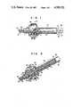
- FIG. 1is a side view, in partial cross-section, of the connector in accordance with the invention, showing various features thereof in assembled condition with a fiber optic cable;
- FIG. 2is a perspective view in partial cut away showing the connector of FIG. 1 as assembled with a fiber optic cable;
- FIG. 3is an exploded view of the connector in accordance with the invention showing the various elements thereof, and how they fit together, in the absence of a fiber optic cable.
- the cable 33is of the type which includes an outer covering sheath 35, a layer of strength fibers 37, typically made of Kevlar® as marketed by DuPont, a buffer layer 41, typically of a silicone type material, and the inner fiber or fibers 47, which fibers 47 can be a single fiber as in a single mode cable or a multitude of fibers clustered together as in a multimode cable.
- the fibershall refer to both multimode as well as single mode fibers and generally refers to the waveguide within which light travels, which waveguide includes a core of a glass material through which the light travels surrounded by a cladding which is also of glass material, but is of slightly different refractive index than the core.
- the connectorincludes a two part clamping member 5 made up of preferably plastic and including a top part 1 and a bottom part 3.
- the plastic parts 1 and 3respectively include a V-groove of progressively decreasing size toward the termination end of the clamping body 5, which V-groove has three portions, a smaller size portion 49 located proximate the termination end or surface 57 of the clamping body 5, an intermediate size V-groove portion 43 and a larger cylindrical portion 45, which when the parts 1 and 3 are assembled together to form the body 5, forms a varying diameter passage through the clamping body 5.
- the diameter of the smaller V-groove portion 49is selected so as to snugly hold the fiber 47 of a fiber optic cable 33 therein when the body 5 is assembled together.
- the diameter of the intermediate passage 43is selected so as to snugly hold the fiber 47 covered with the buffer layer 41.
- the buffer layerterminates at portion 53 slightly before the reducing of the diameter of the passage and the fiber itself is cleaved flush to terminate at point 55 flush with the face 57 of the clamp body 5.
- the fiberis held by clamping both directly on the fiber portion 47 as well as on the buffer portion 41.
- a tube 19which extends out the rear of the clamping member for at least a portion thereof.
- the tube 19includes a flange 17 which is received within a corresponding slot 15 which is molded into the clamping member 5. Accordingly, the dimension of the passage portion 45 must be sufficiently large as to permit the tube 45 to pass therethrough and extend out the rear of the clamp body 5.
- the fiber covered with the buffer 41extends through the tube and out the rear of the connector into the cable assembly 33.
- the clamp body parts 1 and 3are held together as a clamp body 5 by means of a split sleeve 9 which is sized to be of a slightly smaller diameter than the front portions 61 of the clamp body 5.
- the split sleeve 7includes a split portion 9 which allows it to compressively expand to fit over the front portion 61 of the clamp body 5 and hold the clamp body 5 together in clamping relationship with respect to the buffer 41 and the fiber 47 itself, of the fiber optic cable assembly 33 as held therein.
- the front portion 61extends out the front of the sleeve 7 for a predetermined distance and as a result of the sleeve 7 being received over the front portion 61 of the clamp body 5, a more effective holding is achieved by means of direct pressure being exerted on both directly on the fiber 47 as well as directly on the buffer portion 41.
- the sleeve 7includes a slot 11 to accommodate a keying mechanism 13 on the largest diameter portion 63 of the clamp body 5. The function of this key mechanism or projection 13, as shown in FIG. 3, will be explained in greater detail later.
- a crimp sleeve 21, including a projecting abutment flange 23,is received over the middle diameter portion 65 of the rear of the clamp body 5.
- the crimp sleeve 21extends a distance coextensive with the projection of the tube 19 out the rear of the clamp body 5 and abuts at flange portion 23 against abutment 25 of larger diameter portion 63 of the clamp body 5.
- the outer sheath 35 and strength layer or Kevlar® fibers 37 of the fiber optic cable assembly 33is received between the outer surface of the tube 19 and the inner surface of the crimp sleeve 21 with the outer surface of the tube 19 serving as a crimping support so that upon crimping of the sleeve 21, the sheath 35 Kevlar fibers 37 are securely held by the crimp sleeve 21 against the outer surface of tube 19.
- a coupling nut 27is also then received over the exterior of the crimp sleeve 21 and includes threads 29 for threading and connecting the connector assembly to another connector or other assembly through an adapter constructed for engaging the threads 39.
- the coupling nut 27includes a gnarled or rough outer surface 59 to permit or facilitate threading.
- this keying mechanismis adapted to be received within a slot in a sleeve or tubular adapter for the connector to ensure that the fiber is always connected at the same relative rotational position to another fiber and thus, scarring of the end of the fiber is avoided.
- Examples of such an adapterare found in copending application Ser. Nos. 757,097 and 766,743 of Mark Margolin, et al.
- the two part body 5is preferably made of a plastics material, typically Petra®, as sold by Allied Corporation, which is a polyester resin, typically polyethylene terephthalate.
- the sleeve 7is typically of steel or other metal which has a spring memory so as to compress the parts 1 and 3 together upon expansion as a result of it being received over the smaller diameter portion 61 of the body 5.
- the crimp sleeve 21is typically made of metal such as steel or brass which does not have a spring memory and therefore retains its deformed shape when crimped.
- the tube 19should be typically of a metal which is not easily deformable, again steel or brass, depending on how it is tempered.
- the coupling nutwould typically be manufactured of a metal, also steel or brass.
Landscapes
- Physics & Mathematics (AREA)
- General Physics & Mathematics (AREA)
- Optics & Photonics (AREA)
- Mechanical Coupling Of Light Guides (AREA)
Abstract
Description
Claims (15)
Priority Applications (3)
| Application Number | Priority Date | Filing Date | Title |
|---|---|---|---|
| US06/818,576US4705352A (en) | 1985-12-30 | 1985-12-30 | Fiber optic connector |
| EP19860904996EP0253821A4 (en) | 1985-12-30 | 1986-04-11 | CONNECTOR OF TWO OPTICAL FIBERS. |
| PCT/US1986/000754WO1987004262A1 (en) | 1985-12-30 | 1986-04-11 | Fiber optic connector |
Applications Claiming Priority (1)
| Application Number | Priority Date | Filing Date | Title |
|---|---|---|---|
| US06/818,576US4705352A (en) | 1985-12-30 | 1985-12-30 | Fiber optic connector |
Publications (1)
| Publication Number | Publication Date |
|---|---|
| US4705352Atrue US4705352A (en) | 1987-11-10 |
Family
ID=25225862
Family Applications (1)
| Application Number | Title | Priority Date | Filing Date |
|---|---|---|---|
| US06/818,576Expired - LifetimeUS4705352A (en) | 1985-12-30 | 1985-12-30 | Fiber optic connector |
Country Status (3)
| Country | Link |
|---|---|
| US (1) | US4705352A (en) |
| EP (1) | EP0253821A4 (en) |
| WO (1) | WO1987004262A1 (en) |
Cited By (58)
| Publication number | Priority date | Publication date | Assignee | Title |
|---|---|---|---|---|
| US4792205A (en)* | 1986-05-15 | 1988-12-20 | Radiall Industrie | Ferrule of a connector for single-mode optical fibers with polarization maintenance and the process for its adjustment |
| US4898449A (en)* | 1987-08-04 | 1990-02-06 | U.S. Philips Corp. | Connector for the detachable connection of light conducting fibres |
| US4898446A (en)* | 1988-10-28 | 1990-02-06 | American Telephone And Telegraph Company, At&T Bell Laboratories | Optical fiber connector |
| US5078465A (en)* | 1990-01-03 | 1992-01-07 | The Charles Stark Draper Laboratory, Inc. | Fused fiber optic coupler |
| US5096276A (en)* | 1988-02-23 | 1992-03-17 | Amp Incorporated | Sheath connector for an optical cable |
| US5181267A (en)* | 1988-02-23 | 1993-01-19 | Amp Incorporated | Sheath connector for an optical cable |
| US5274903A (en)* | 1991-11-08 | 1994-01-04 | Molex Incorporated | Crimping tool system for optical fiber cables |
| US5390270A (en)* | 1989-11-28 | 1995-02-14 | Kel Corporation | Optical fiber ferrule assemblies |
| US5530785A (en)* | 1993-12-28 | 1996-06-25 | Fujitsu Limited | Optical fiber cable fixing structure and cable holder used for fixing the cable |
| US5598500A (en)* | 1995-01-09 | 1997-01-28 | France Telecom | Fixing, earthing and sealing device for optical cables |
| US5644672A (en)* | 1994-12-05 | 1997-07-01 | Asahi Kohoen, Co., Ltd. | Optical fiber holder used in optical connectors |
| US5668906A (en)* | 1995-06-13 | 1997-09-16 | Sumitomo Wiring Systems, Ltd. | Connector assembly for elongated elements |
| US5802229A (en)* | 1995-10-31 | 1998-09-01 | Indigo, Medical, Inc. | Fiber optic radiation transmisson system connector for an optical fiber and methods of usine same |
| US5862289A (en)* | 1997-02-18 | 1999-01-19 | Amphenol Corporation | Adhesiveless fiber optic connector, and an apparatus and method for terminating a fiber optic cable to an adhesiveless fiber optic connector |
| US6510260B2 (en) | 2001-01-02 | 2003-01-21 | Finisar Corporation, Inc. | N×N optical switching device based on thermal optic induced internal reflection effect |
| US20030063869A1 (en)* | 2001-05-07 | 2003-04-03 | Elkins Robert B. | Module attachment for securing at least one optical waveguide and methods therefor |
| US20040062488A1 (en)* | 2002-09-26 | 2004-04-01 | Charles Wood | Fiber optic adapter sleeve |
| US20040240830A1 (en)* | 2001-10-04 | 2004-12-02 | Jan Watte | Closing mechanism for a mechanical optical fibre splice |
| US20050041926A1 (en)* | 2001-05-07 | 2005-02-24 | Elkins Robert B. | Panel assembly with dense fiber output array |
| US20050281510A1 (en)* | 2004-06-17 | 2005-12-22 | Vo Chanh C | Fiber optic cable and plug assembly |
| US20060045430A1 (en)* | 2004-08-24 | 2006-03-02 | Thomas Theuerkorn | Fiber optic receptacle and plug assemblies with alignment and keying features |
| US7014372B2 (en) | 2001-10-04 | 2006-03-21 | Tyco Electronics Raychem Nv | Method and apparatus for splicing optical fibres |
| US20070071578A1 (en)* | 2005-09-20 | 2007-03-29 | Piolax, Inc. | Shaft fixing clip and shaft fixing structure using the clip |
| US20080008430A1 (en)* | 2006-07-06 | 2008-01-10 | Anthony Stephen Kewitsch | Shape-Retaining Fiber Optic Cables Having Limited Bend Radius |
| US20080080817A1 (en)* | 2000-05-26 | 2008-04-03 | Melton Stuart R | Fiber optic drop cables and preconnectorized assemblies having toning portions |
| US20090041411A1 (en)* | 2000-05-26 | 2009-02-12 | Melton Stuart R | Fiber Optic Drop Cables and Preconnectorized Assemblies |
| US20090067789A1 (en)* | 2006-08-01 | 2009-03-12 | Adc Telecommunications, Inc. | Dual inner diameter ferrule device and method |
| US7572065B2 (en) | 2007-01-24 | 2009-08-11 | Adc Telecommunications, Inc. | Hardened fiber optic connector |
| US7591595B2 (en) | 2007-01-24 | 2009-09-22 | Adc Telelcommunications, Inc. | Hardened fiber optic adapter |
| US7614797B2 (en) | 2007-01-24 | 2009-11-10 | Adc Telecommunications, Inc. | Fiber optic connector mechanical interface converter |
| US7677814B2 (en) | 2007-05-06 | 2010-03-16 | Adc Telecommunications, Inc. | Mechanical interface converter for making non-ruggedized fiber optic connectors compatible with a ruggedized fiber optic adapter |
| US7686519B2 (en) | 2007-06-18 | 2010-03-30 | Adc Telecommunications, Inc. | Hardened fiber optic housing and cable assembly |
| US7722258B2 (en) | 2007-05-06 | 2010-05-25 | Adc Telecommunications, Inc. | Interface converter for SC fiber optic connectors |
| US7744286B2 (en) | 2007-12-11 | 2010-06-29 | Adc Telecommunications, Inc. | Hardened fiber optic connection system with multiple configurations |
| US20110103748A1 (en)* | 2009-11-04 | 2011-05-05 | Michael James Ott | Fiber optic ferrule assembly with transitioning insert |
| USRE42522E1 (en) | 2003-09-08 | 2011-07-05 | Adc Telecommunications, Inc. | Ruggedized fiber optic connection |
| CN102269846A (en)* | 2010-06-04 | 2011-12-07 | 泰科电子(上海)有限公司 | Device for fixing at least two optical fiber connectors |
| US20150036981A1 (en)* | 2009-06-03 | 2015-02-05 | Japan Aviation Electronics Industry, Limited | Polishing jig, ferrule, and optical connector |
| US8989541B2 (en) | 2006-08-01 | 2015-03-24 | Adc Telecommunications, Inc. | Cable and dual inner diameter ferrule device with smooth internal contours and method |
| US9239441B2 (en) | 2000-05-26 | 2016-01-19 | Corning Cable Systems Llc | Fiber optic drop cables and preconnectorized assemblies having toning portions |
| US9341784B2 (en) | 2010-02-12 | 2016-05-17 | Adc Telecommunications (Shanghai) Distribution Co., Ltd. | Optical fiber filter device and method for manufacturing the same |
| US20160139345A1 (en)* | 2013-01-23 | 2016-05-19 | Commscope, Inc. Of North Carolina | Cylindrical Optical Ferrule Alignment Apparatus |
| US10191226B2 (en) | 2013-01-23 | 2019-01-29 | Commscope, Inc. Of North Carolina | Cylindrical optical ferrule alignment apparatus |
| US10359577B2 (en) | 2017-06-28 | 2019-07-23 | Corning Research & Development Corporation | Multiports and optical connectors with rotationally discrete locking and keying features |
| US10379298B2 (en) | 2017-06-28 | 2019-08-13 | Corning Research & Development Corporation | Fiber optic connectors and multiport assemblies including retention features |
| US10444443B2 (en) | 2013-06-27 | 2019-10-15 | CommScope Connectivity Belgium BVBA | Fiber optic cable anchoring device for use with fiber optic connectors and methods of using the same |
| US11187859B2 (en) | 2017-06-28 | 2021-11-30 | Corning Research & Development Corporation | Fiber optic connectors and methods of making the same |
| US11294133B2 (en) | 2019-07-31 | 2022-04-05 | Corning Research & Development Corporation | Fiber optic networks using multiports and cable assemblies with cable-to-connector orientation |
| US11536921B2 (en) | 2020-02-11 | 2022-12-27 | Corning Research & Development Corporation | Fiber optic terminals having one or more loopback assemblies |
| US11604320B2 (en) | 2020-09-30 | 2023-03-14 | Corning Research & Development Corporation | Connector assemblies for telecommunication enclosures |
| US11686913B2 (en) | 2020-11-30 | 2023-06-27 | Corning Research & Development Corporation | Fiber optic cable assemblies and connector assemblies having a crimp ring and crimp body and methods of fabricating the same |
| US11880076B2 (en) | 2020-11-30 | 2024-01-23 | Corning Research & Development Corporation | Fiber optic adapter assemblies including a conversion housing and a release housing |
| US11927810B2 (en) | 2020-11-30 | 2024-03-12 | Corning Research & Development Corporation | Fiber optic adapter assemblies including a conversion housing and a release member |
| US11994722B2 (en) | 2020-11-30 | 2024-05-28 | Corning Research & Development Corporation | Fiber optic adapter assemblies including an adapter housing and a locking housing |
| US12013577B2 (en) | 2011-10-10 | 2024-06-18 | Commscope Technologies Llc | Cable and dual inner diameter ferrule device with smooth internal contours and method |
| US12019279B2 (en) | 2019-05-31 | 2024-06-25 | Corning Research & Development Corporation | Multiports and other devices having optical connection ports with sliding actuators and methods of making the same |
| US12271040B2 (en) | 2017-06-28 | 2025-04-08 | Corning Research & Development Corporation | Fiber optic extender ports, assemblies and methods of making the same |
| US12372727B2 (en) | 2020-10-30 | 2025-07-29 | Corning Research & Development Corporation | Female fiber optic connectors having a rocker latch arm and methods of making the same |
Families Citing this family (4)
| Publication number | Priority date | Publication date | Assignee | Title |
|---|---|---|---|---|
| US5028114A (en)* | 1988-09-29 | 1991-07-02 | Siemens Aktiengesellschaft | Plug connector for fiber optic cables |
| DE8907863U1 (en)* | 1989-06-28 | 1989-08-31 | Standard Elektrik Lorenz Ag, 7000 Stuttgart | Coupling plug with securing element for optical fiber |
| DE9306328U1 (en)* | 1993-04-27 | 1993-08-19 | Niebuhr Optoelektronik GmbH, 22525 Hamburg | Fiber holder |
| US5909526A (en)* | 1998-04-08 | 1999-06-01 | Molex Incorporated | Fiber optic connector assembly |
Citations (10)
| Publication number | Priority date | Publication date | Assignee | Title |
|---|---|---|---|---|
| US4198119A (en)* | 1978-09-13 | 1980-04-15 | International Business Machines Corporation | Connector for optical cable |
| US4447121A (en)* | 1981-11-06 | 1984-05-08 | Amp Incorporated | Connector for fiber optic member |
| US4448478A (en)* | 1979-05-08 | 1984-05-15 | International Telephone & Telegraph Corporation | Fiber optic connector |
| US4461539A (en)* | 1981-06-01 | 1984-07-24 | Switchcraft, Inc. | Fiber optic connector assembly with slidable spacer |
| US4477146A (en)* | 1981-03-16 | 1984-10-16 | Amp Incorporated | Optical waveguide connector |
| US4479910A (en)* | 1981-04-22 | 1984-10-30 | Nippon Telegraph & Telephone Public Corp. | Method for production of optical fiber connectors |
| US4607911A (en)* | 1983-10-03 | 1986-08-26 | Conax Buffalo Corporation | Connector for an optical fiber having a stationary clamp engaged and operated by a rotatable member |
| US4615581A (en)* | 1982-03-05 | 1986-10-07 | Nippon Electric Co., Ltd. | Optical fiber connector |
| US4673016A (en)* | 1984-09-17 | 1987-06-16 | Holland Mechanics B.V. | Method and apparatus for laying a pneumatic tire around a wheel rim |
| US4684205A (en)* | 1985-07-19 | 1987-08-04 | Allied Corporation | Fiber optic connector with compensating mechanism |
- 1985
- 1985-12-30USUS06/818,576patent/US4705352A/ennot_activeExpired - Lifetime
- 1986
- 1986-04-11EPEP19860904996patent/EP0253821A4/ennot_activeWithdrawn
- 1986-04-11WOPCT/US1986/000754patent/WO1987004262A1/ennot_activeApplication Discontinuation
Patent Citations (10)
| Publication number | Priority date | Publication date | Assignee | Title |
|---|---|---|---|---|
| US4198119A (en)* | 1978-09-13 | 1980-04-15 | International Business Machines Corporation | Connector for optical cable |
| US4448478A (en)* | 1979-05-08 | 1984-05-15 | International Telephone & Telegraph Corporation | Fiber optic connector |
| US4477146A (en)* | 1981-03-16 | 1984-10-16 | Amp Incorporated | Optical waveguide connector |
| US4479910A (en)* | 1981-04-22 | 1984-10-30 | Nippon Telegraph & Telephone Public Corp. | Method for production of optical fiber connectors |
| US4461539A (en)* | 1981-06-01 | 1984-07-24 | Switchcraft, Inc. | Fiber optic connector assembly with slidable spacer |
| US4447121A (en)* | 1981-11-06 | 1984-05-08 | Amp Incorporated | Connector for fiber optic member |
| US4615581A (en)* | 1982-03-05 | 1986-10-07 | Nippon Electric Co., Ltd. | Optical fiber connector |
| US4607911A (en)* | 1983-10-03 | 1986-08-26 | Conax Buffalo Corporation | Connector for an optical fiber having a stationary clamp engaged and operated by a rotatable member |
| US4673016A (en)* | 1984-09-17 | 1987-06-16 | Holland Mechanics B.V. | Method and apparatus for laying a pneumatic tire around a wheel rim |
| US4684205A (en)* | 1985-07-19 | 1987-08-04 | Allied Corporation | Fiber optic connector with compensating mechanism |
Cited By (146)
| Publication number | Priority date | Publication date | Assignee | Title |
|---|---|---|---|---|
| US4792205A (en)* | 1986-05-15 | 1988-12-20 | Radiall Industrie | Ferrule of a connector for single-mode optical fibers with polarization maintenance and the process for its adjustment |
| US4898449A (en)* | 1987-08-04 | 1990-02-06 | U.S. Philips Corp. | Connector for the detachable connection of light conducting fibres |
| US5096276A (en)* | 1988-02-23 | 1992-03-17 | Amp Incorporated | Sheath connector for an optical cable |
| US5181267A (en)* | 1988-02-23 | 1993-01-19 | Amp Incorporated | Sheath connector for an optical cable |
| US4898446A (en)* | 1988-10-28 | 1990-02-06 | American Telephone And Telegraph Company, At&T Bell Laboratories | Optical fiber connector |
| US5390270A (en)* | 1989-11-28 | 1995-02-14 | Kel Corporation | Optical fiber ferrule assemblies |
| US5078465A (en)* | 1990-01-03 | 1992-01-07 | The Charles Stark Draper Laboratory, Inc. | Fused fiber optic coupler |
| US5274903A (en)* | 1991-11-08 | 1994-01-04 | Molex Incorporated | Crimping tool system for optical fiber cables |
| US5530785A (en)* | 1993-12-28 | 1996-06-25 | Fujitsu Limited | Optical fiber cable fixing structure and cable holder used for fixing the cable |
| US5644672A (en)* | 1994-12-05 | 1997-07-01 | Asahi Kohoen, Co., Ltd. | Optical fiber holder used in optical connectors |
| US5598500A (en)* | 1995-01-09 | 1997-01-28 | France Telecom | Fixing, earthing and sealing device for optical cables |
| US5668906A (en)* | 1995-06-13 | 1997-09-16 | Sumitomo Wiring Systems, Ltd. | Connector assembly for elongated elements |
| US5802229A (en)* | 1995-10-31 | 1998-09-01 | Indigo, Medical, Inc. | Fiber optic radiation transmisson system connector for an optical fiber and methods of usine same |
| US5848209A (en)* | 1995-10-31 | 1998-12-08 | Indigo Medical Inc. | Connection apparatus with optical fiber coding and detection means or with radiation emitter |
| US5875275A (en)* | 1995-10-31 | 1999-02-23 | Indigo Medical, Inc. | Methods of connecting an optical fiber and methods of providing radiation from an optical fiber |
| US5862289A (en)* | 1997-02-18 | 1999-01-19 | Amphenol Corporation | Adhesiveless fiber optic connector, and an apparatus and method for terminating a fiber optic cable to an adhesiveless fiber optic connector |
| US20090041411A1 (en)* | 2000-05-26 | 2009-02-12 | Melton Stuart R | Fiber Optic Drop Cables and Preconnectorized Assemblies |
| US7467896B2 (en) | 2000-05-26 | 2008-12-23 | Corning Cable Systems Llc | Fiber optic drop cables and preconnectorized assemblies |
| US20090060423A1 (en)* | 2000-05-26 | 2009-03-05 | Melton Stuart R | Fiber Optic Drop Cables and Preconnectorized Assemblies Having Toning Portions |
| US20080080817A1 (en)* | 2000-05-26 | 2008-04-03 | Melton Stuart R | Fiber optic drop cables and preconnectorized assemblies having toning portions |
| US7785015B2 (en) | 2000-05-26 | 2010-08-31 | Corning Cable Systems Llc | Fiber optic drop cables and preconnectorized assemblies |
| US7918609B2 (en) | 2000-05-26 | 2011-04-05 | Corning Cable Systems Llc | Fiber optic drop cables and preconnectorized assemblies |
| US9239441B2 (en) | 2000-05-26 | 2016-01-19 | Corning Cable Systems Llc | Fiber optic drop cables and preconnectorized assemblies having toning portions |
| US10114176B2 (en) | 2000-05-26 | 2018-10-30 | Corning Optical Communications LLC | Fiber optic drop cables and preconnectorized assemblies |
| US7881576B2 (en) | 2000-05-26 | 2011-02-01 | Corning Cable Systems Llc | Fiber optic drop cables and preconnectorized assemblies |
| US6510260B2 (en) | 2001-01-02 | 2003-01-21 | Finisar Corporation, Inc. | N×N optical switching device based on thermal optic induced internal reflection effect |
| US20050041926A1 (en)* | 2001-05-07 | 2005-02-24 | Elkins Robert B. | Panel assembly with dense fiber output array |
| US20030063869A1 (en)* | 2001-05-07 | 2003-04-03 | Elkins Robert B. | Module attachment for securing at least one optical waveguide and methods therefor |
| US7014372B2 (en) | 2001-10-04 | 2006-03-21 | Tyco Electronics Raychem Nv | Method and apparatus for splicing optical fibres |
| US20040240830A1 (en)* | 2001-10-04 | 2004-12-02 | Jan Watte | Closing mechanism for a mechanical optical fibre splice |
| US20040062488A1 (en)* | 2002-09-26 | 2004-04-01 | Charles Wood | Fiber optic adapter sleeve |
| USRE42522E1 (en) | 2003-09-08 | 2011-07-05 | Adc Telecommunications, Inc. | Ruggedized fiber optic connection |
| CN100510819C (en)* | 2004-06-17 | 2009-07-08 | 康宁光缆系统有限责任公司 | Optical cable and plug assembly |
| US20050281510A1 (en)* | 2004-06-17 | 2005-12-22 | Vo Chanh C | Fiber optic cable and plug assembly |
| WO2006009597A1 (en)* | 2004-06-17 | 2006-01-26 | Corning Cable Systems Llc | Fiber optic cable and plug assembly |
| US7146090B2 (en) | 2004-06-17 | 2006-12-05 | Corning Cable Systems Llc | Fiber optic cable and plug assembly |
| US20060045430A1 (en)* | 2004-08-24 | 2006-03-02 | Thomas Theuerkorn | Fiber optic receptacle and plug assemblies with alignment and keying features |
| US7137742B2 (en)* | 2004-08-24 | 2006-11-21 | Corning Cable Systems Llc | Fiber optic receptacle and plug assemblies with alignment and keying features |
| US20070071578A1 (en)* | 2005-09-20 | 2007-03-29 | Piolax, Inc. | Shaft fixing clip and shaft fixing structure using the clip |
| US7704008B2 (en)* | 2005-09-20 | 2010-04-27 | Piolax, Inc. | Shaft fixing clip and shaft fixing structure using the clip |
| US20080008430A1 (en)* | 2006-07-06 | 2008-01-10 | Anthony Stephen Kewitsch | Shape-Retaining Fiber Optic Cables Having Limited Bend Radius |
| US7460753B2 (en)* | 2006-07-06 | 2008-12-02 | Anthony Stephen Kewitsch | Shape-retaining fiber optic cables having limited bend radius |
| US10634856B2 (en) | 2006-08-01 | 2020-04-28 | Commscope Technologies Llc | Dual inner diameter ferrule device and method |
| US10295757B2 (en) | 2006-08-01 | 2019-05-21 | Commscope Technologies Llc | Fiber optic ferrule with smooth internal contours and method of terminating fiber with the ferrule |
| US9348095B2 (en) | 2006-08-01 | 2016-05-24 | Commscope Technologies Llc | Cable and dual inner diameter ferrule device with smooth internal contours and method |
| US11467353B2 (en) | 2006-08-01 | 2022-10-11 | Commscope Technologies Llc | Cable and dual inner diameter ferrule device with smooth internal contours and method |
| US9835806B2 (en) | 2006-08-01 | 2017-12-05 | Commscope Technologies Llc | Fiber optic cable and ferrule with smooth internal contours and method of terminating fiber with the ferrule |
| US20090067789A1 (en)* | 2006-08-01 | 2009-03-12 | Adc Telecommunications, Inc. | Dual inner diameter ferrule device and method |
| US9477047B2 (en) | 2006-08-01 | 2016-10-25 | Commscope Technologies Llc | Dual inner diameter ferrule device and method |
| US12124091B2 (en) | 2006-08-01 | 2024-10-22 | Commscope Technologies Llc | Dual inner diameter ferrule device and method |
| US11397296B2 (en) | 2006-08-01 | 2022-07-26 | Commscope Technologies Llc | Dual inner diameter ferrule device and method |
| US10976503B2 (en) | 2006-08-01 | 2021-04-13 | Commscope Technologies Llc | Dual inner diameter ferrule device and method |
| US8989541B2 (en) | 2006-08-01 | 2015-03-24 | Adc Telecommunications, Inc. | Cable and dual inner diameter ferrule device with smooth internal contours and method |
| US10942317B2 (en) | 2006-08-01 | 2021-03-09 | Commscope Technologies Llc | Fiber optic ferrule with smooth internal contours |
| US10107971B2 (en) | 2006-08-01 | 2018-10-23 | Commscope Technologies Llc | Dual inner diameter ferrule device and method |
| US11409057B2 (en) | 2007-01-24 | 2022-08-09 | Commscope Technologies Llc | Hardened fiber optic connector |
| US10877224B2 (en) | 2007-01-24 | 2020-12-29 | Commscope Technologies Llc | Fiber optic adapter |
| US7591595B2 (en) | 2007-01-24 | 2009-09-22 | Adc Telelcommunications, Inc. | Hardened fiber optic adapter |
| US8770862B2 (en) | 2007-01-24 | 2014-07-08 | Adc Telecommunications, Inc. | Hardened fiber optic connector |
| US7572065B2 (en) | 2007-01-24 | 2009-08-11 | Adc Telecommunications, Inc. | Hardened fiber optic connector |
| US7614797B2 (en) | 2007-01-24 | 2009-11-10 | Adc Telecommunications, Inc. | Fiber optic connector mechanical interface converter |
| US12111502B2 (en) | 2007-01-24 | 2024-10-08 | Commscope Technologies Llc | Hardened fiber optic connector |
| US9664862B2 (en) | 2007-01-24 | 2017-05-30 | Commscope Technologies Llc | Hardened fiber optic connector |
| US8137002B2 (en) | 2007-05-06 | 2012-03-20 | Adc Telecommunications, Inc. | Mechanical interface converter for making non-ruggedized fiber optic connectors compatible with a ruggedized fiber optic adapter |
| US8128294B2 (en) | 2007-05-06 | 2012-03-06 | Adc Telecommunications, Inc. | Interface converter for SC fiber optic connectors |
| US7677814B2 (en) | 2007-05-06 | 2010-03-16 | Adc Telecommunications, Inc. | Mechanical interface converter for making non-ruggedized fiber optic connectors compatible with a ruggedized fiber optic adapter |
| US7722258B2 (en) | 2007-05-06 | 2010-05-25 | Adc Telecommunications, Inc. | Interface converter for SC fiber optic connectors |
| US7686519B2 (en) | 2007-06-18 | 2010-03-30 | Adc Telecommunications, Inc. | Hardened fiber optic housing and cable assembly |
| US10101538B2 (en) | 2007-12-11 | 2018-10-16 | Commscope Technologies Llc | Hardened fiber optic connector compatible with hardened and non-hardened fiber optic adapters |
| US10746939B2 (en) | 2007-12-11 | 2020-08-18 | Commscope Technologies Llc | Hardened fiber optic connector compatible with hardened and non-hardened fiber optic adapters |
| US8414196B2 (en) | 2007-12-11 | 2013-04-09 | Adc Telecommunications, Inc. | Optical fiber connection system with locking member |
| US11275220B2 (en) | 2007-12-11 | 2022-03-15 | Commscope Technologies Llc | Hardened fiber optic connector compatible with hardened and non-hardened fiber optic adapters |
| US7942590B2 (en) | 2007-12-11 | 2011-05-17 | Adc Telecommunications, Inc. | Hardened fiber optic connector and cable assembly with multiple configurations |
| US8202008B2 (en) | 2007-12-11 | 2012-06-19 | Adc Telecommunications, Inc. | Hardened fiber optic connection system with multiple configurations |
| US7959361B2 (en) | 2007-12-11 | 2011-06-14 | Adc Telecommunications, Inc. | Hardened fiber optic connection system |
| US7744288B2 (en) | 2007-12-11 | 2010-06-29 | Adc Telecommunications, Inc. | Hardened fiber optic connector compatible with hardened and non-hardened fiber optic adapters |
| US7762726B2 (en) | 2007-12-11 | 2010-07-27 | Adc Telecommunications, Inc. | Hardened fiber optic connection system |
| US11867950B2 (en) | 2007-12-11 | 2024-01-09 | Commscope Technologies Llc | Hardened fiber optic connector compatible with hardened and non-hardened fiber optic adapters |
| US9482829B2 (en) | 2007-12-11 | 2016-11-01 | Commscope Technologies Llc | Hardened fiber optic connector compatible with hardened and non-hardened fiber optic adapters |
| US12181718B2 (en) | 2007-12-11 | 2024-12-31 | Commscope Technologies Llc | Hardened fiber optic connector compatible with hardened and non-hardened fiber optic adapters |
| US7744286B2 (en) | 2007-12-11 | 2010-06-29 | Adc Telecommunications, Inc. | Hardened fiber optic connection system with multiple configurations |
| US20150036981A1 (en)* | 2009-06-03 | 2015-02-05 | Japan Aviation Electronics Industry, Limited | Polishing jig, ferrule, and optical connector |
| US9429720B2 (en)* | 2009-06-03 | 2016-08-30 | Japan Aviation Electronics Industry, Limited | Polishing jig, ferrule, and optical connector |
| US8702320B2 (en) | 2009-11-04 | 2014-04-22 | Adc Telecommunications, Inc. | Fiber optic ferrule assembly with transitioning insert |
| US20110103748A1 (en)* | 2009-11-04 | 2011-05-05 | Michael James Ott | Fiber optic ferrule assembly with transitioning insert |
| US9341784B2 (en) | 2010-02-12 | 2016-05-17 | Adc Telecommunications (Shanghai) Distribution Co., Ltd. | Optical fiber filter device and method for manufacturing the same |
| CN102269846A (en)* | 2010-06-04 | 2011-12-07 | 泰科电子(上海)有限公司 | Device for fixing at least two optical fiber connectors |
| CN102269846B (en)* | 2010-06-04 | 2014-07-16 | 泰科电子(上海)有限公司 | Device for fixing at least two optical fiber connectors |
| US12013577B2 (en) | 2011-10-10 | 2024-06-18 | Commscope Technologies Llc | Cable and dual inner diameter ferrule device with smooth internal contours and method |
| US12326598B2 (en) | 2011-10-10 | 2025-06-10 | Commscope Technologies Llc | Cable and dual inner diameter ferrule device with smooth internal contours and method |
| US10754104B2 (en) | 2013-01-23 | 2020-08-25 | Commscope, Inc. Of North Carolina | Cylindrical optical ferrule alignment apparatus |
| US10191226B2 (en) | 2013-01-23 | 2019-01-29 | Commscope, Inc. Of North Carolina | Cylindrical optical ferrule alignment apparatus |
| US20160139345A1 (en)* | 2013-01-23 | 2016-05-19 | Commscope, Inc. Of North Carolina | Cylindrical Optical Ferrule Alignment Apparatus |
| US9835808B2 (en)* | 2013-01-23 | 2017-12-05 | Commscope, Inc. Of North Carolina | Cylindrical optical ferrule alignment apparatus |
| US10444443B2 (en) | 2013-06-27 | 2019-10-15 | CommScope Connectivity Belgium BVBA | Fiber optic cable anchoring device for use with fiber optic connectors and methods of using the same |
| US12117658B2 (en) | 2013-06-27 | 2024-10-15 | CommScope Connectivity Belgium BVBA | Fiber optic cable anchoring device for use with fiber optic connectors and methods of using the same |
| US11531168B2 (en) | 2017-06-28 | 2022-12-20 | Corning Research & Development Corporation | Fiber optic connectors having a keying structure and methods of making the same |
| US11886017B2 (en) | 2017-06-28 | 2024-01-30 | Corning Research & Development Corporation | Multiports and other devices having connection ports with securing features and methods of making the same |
| US12276846B2 (en) | 2017-06-28 | 2025-04-15 | Corning Research & Development Corporation | Compact fiber optic connectors, cable assemblies and methods of making the same |
| US11300735B2 (en) | 2017-06-28 | 2022-04-12 | Corning Research & Development Corporation | Compact fiber optic connectors having multiple connector footprints, along with cable assemblies and methods of making the same |
| US11307364B2 (en) | 2017-06-28 | 2022-04-19 | Corning Research & Development Corporation | Compact fiber optic connectors having multiple connector footprints, along with cable assemblies and methods of making the same |
| US11287581B2 (en) | 2017-06-28 | 2022-03-29 | Corning Research & Development Corporation | Compact fiber optic connectors, cable assemblies and methods of making the same |
| US11262509B2 (en) | 2017-06-28 | 2022-03-01 | Corning Research & Development Corporation | Compact fiber optic connectors having multiple connector footprints, along with cable assemblies and methods of making the same |
| US11460646B2 (en) | 2017-06-28 | 2022-10-04 | Corning Research & Development Corporation | Fiber optic connectors and multiport assemblies including retention features |
| US11215768B2 (en) | 2017-06-28 | 2022-01-04 | Corning Research & Development Corporation | Fiber optic connectors and connectorization employing adhesive admitting adapters |
| US11493699B2 (en) | 2017-06-28 | 2022-11-08 | Corning Research & Development Corporation | Multifiber fiber optic connectors, cable assemblies and methods of making the same |
| US11493700B2 (en) | 2017-06-28 | 2022-11-08 | Corning Research & Development Corporation | Compact fiber optic connectors, cable assemblies and methods of making the same |
| US11187859B2 (en) | 2017-06-28 | 2021-11-30 | Corning Research & Development Corporation | Fiber optic connectors and methods of making the same |
| US11536913B2 (en) | 2017-06-28 | 2022-12-27 | Corning Research & Development Corporation | Fiber optic connectors and connectorization employing adhesive admitting adapters |
| US11287582B2 (en) | 2017-06-28 | 2022-03-29 | Corning Research & Development Corporation | Compact fiber optic connectors, cable assemblies and methods of making the same |
| US11543600B2 (en) | 2017-06-28 | 2023-01-03 | Corning Research & Development Corporation | Compact fiber optic connectors having multiple connector footprints, along with cable assemblies and methods of making the same |
| US11579377B2 (en) | 2017-06-28 | 2023-02-14 | Corning Research & Development Corporation | Compact fiber optic connectors, cable assemblies and methods of making the same with alignment elements |
| US12429655B2 (en) | 2017-06-28 | 2025-09-30 | Corning Optical Communications LLC | Multiports having connection ports with associated securing features and methods of making the same |
| US12379551B2 (en) | 2017-06-28 | 2025-08-05 | Corning Optical Communications LLC | Multiports having connection ports formed in the shell and associated securing features |
| US11703646B2 (en) | 2017-06-28 | 2023-07-18 | Corning Research & Development Corporation | Multiports and optical connectors with rotationally discrete locking and keying features |
| US10809463B2 (en) | 2017-06-28 | 2020-10-20 | Corning Research & Development Corporation | Multiports and optical connectors with rotationally discrete locking and keying features |
| US12379552B2 (en) | 2017-06-28 | 2025-08-05 | Corning Research & Development Corporation | Compact fiber optic connectors, cable assemblies and methods of making the same |
| US12298568B2 (en) | 2017-06-28 | 2025-05-13 | Corning Research & Development Corporation | Fiber optic connectors and multiport assemblies including retention features |
| US11906792B2 (en) | 2017-06-28 | 2024-02-20 | Corning Research & Development Corporation | Compact fiber optic connectors having multiple connector footprints, along with cable assemblies and methods of making the same |
| US11914197B2 (en) | 2017-06-28 | 2024-02-27 | Corning Research & Development Corporation | Compact fiber optic connectors having multiple connector footprints, along with cable assemblies and methods of making the same |
| US11914198B2 (en) | 2017-06-28 | 2024-02-27 | Corning Research & Development Corporation | Compact fiber optic connectors having multiple connector footprints, along with cable assemblies and methods of making the same |
| US12353024B2 (en) | 2017-06-28 | 2025-07-08 | Corning Research & Development Corporation | Multiports and optical connectors with rotationally discrete locking and keying features |
| US11940656B2 (en) | 2017-06-28 | 2024-03-26 | Corning Research & Development Corporation | Compact fiber optic connectors, cable assemblies and methods of making the same |
| US11966089B2 (en) | 2017-06-28 | 2024-04-23 | Corning Optical Communications, Llc | Multiports having connection ports formed in the shell and associated securing features |
| US12353025B2 (en) | 2017-06-28 | 2025-07-08 | Corning Optical Communications LLC | Multiports having a connection port insert and methods of making the same |
| US12013578B2 (en) | 2017-06-28 | 2024-06-18 | Corning Research & Development Corporation | Multifiber fiber optic connectors, cable assemblies and methods of making the same |
| US10802228B2 (en) | 2017-06-28 | 2020-10-13 | Corning Research & Development Corporation | Fiber optic connectors and multiport assemblies including retention features |
| US10359577B2 (en) | 2017-06-28 | 2019-07-23 | Corning Research & Development Corporation | Multiports and optical connectors with rotationally discrete locking and keying features |
| US12271040B2 (en) | 2017-06-28 | 2025-04-08 | Corning Research & Development Corporation | Fiber optic extender ports, assemblies and methods of making the same |
| US12092878B2 (en) | 2017-06-28 | 2024-09-17 | Corning Research & Development Corporation | Fiber optic connectors having a keying structure and methods of making the same |
| US10605998B2 (en) | 2017-06-28 | 2020-03-31 | Corning Research & Development Corporation | Fiber optic connectors and connectorization employing adhesive admitting adapters |
| US10429593B2 (en) | 2017-06-28 | 2019-10-01 | Corning Research & Development Corporation | Fiber optic connectors and connectorization employing adapter extensions and/or flexures |
| US10386584B2 (en) | 2017-06-28 | 2019-08-20 | Corning Research & Development Corporation | Optical connectors with locking and keying features for interfacing with multiports |
| US12174432B2 (en) | 2017-06-28 | 2024-12-24 | Corning Research & Development Corporation | Fiber optic connectors and connectorization employing adhesive admitting adapters |
| US10379298B2 (en) | 2017-06-28 | 2019-08-13 | Corning Research & Development Corporation | Fiber optic connectors and multiport assemblies including retention features |
| US12019279B2 (en) | 2019-05-31 | 2024-06-25 | Corning Research & Development Corporation | Multiports and other devices having optical connection ports with sliding actuators and methods of making the same |
| US11294133B2 (en) | 2019-07-31 | 2022-04-05 | Corning Research & Development Corporation | Fiber optic networks using multiports and cable assemblies with cable-to-connector orientation |
| US11536921B2 (en) | 2020-02-11 | 2022-12-27 | Corning Research & Development Corporation | Fiber optic terminals having one or more loopback assemblies |
| US12019285B2 (en) | 2020-09-30 | 2024-06-25 | Corning Research & Development Corporation | Connector assemblies for telecommunication enclosures |
| US11604320B2 (en) | 2020-09-30 | 2023-03-14 | Corning Research & Development Corporation | Connector assemblies for telecommunication enclosures |
| US12372727B2 (en) | 2020-10-30 | 2025-07-29 | Corning Research & Development Corporation | Female fiber optic connectors having a rocker latch arm and methods of making the same |
| US12345927B2 (en) | 2020-11-30 | 2025-07-01 | Corning Research & Development Corporation | Fiber optic adapter assemblies including a conversion housing and a release housing |
| US11994722B2 (en) | 2020-11-30 | 2024-05-28 | Corning Research & Development Corporation | Fiber optic adapter assemblies including an adapter housing and a locking housing |
| US11927810B2 (en) | 2020-11-30 | 2024-03-12 | Corning Research & Development Corporation | Fiber optic adapter assemblies including a conversion housing and a release member |
| US11880076B2 (en) | 2020-11-30 | 2024-01-23 | Corning Research & Development Corporation | Fiber optic adapter assemblies including a conversion housing and a release housing |
| US11686913B2 (en) | 2020-11-30 | 2023-06-27 | Corning Research & Development Corporation | Fiber optic cable assemblies and connector assemblies having a crimp ring and crimp body and methods of fabricating the same |
Also Published As
| Publication number | Publication date |
|---|---|
| EP0253821A4 (en) | 1990-01-08 |
| EP0253821A1 (en) | 1988-01-27 |
| WO1987004262A1 (en) | 1987-07-16 |
Similar Documents
| Publication | Publication Date | Title |
|---|---|---|
| US4705352A (en) | Fiber optic connector | |
| US4515434A (en) | Fiber optic connector | |
| US4964688A (en) | Fiber optic connector element and method for its use | |
| US5923805A (en) | Connector for plastic optical fiber | |
| EP0088410B1 (en) | Optical fiber connectors | |
| US4684205A (en) | Fiber optic connector with compensating mechanism | |
| US4687288A (en) | Fiber optic connector with temperature compensating mechanism | |
| US4877303A (en) | Fiber optic connector element & method for its use | |
| US5971626A (en) | Fiber optic connector and connector sleeve assembly | |
| US4781431A (en) | Lensed optical connector | |
| US4715675A (en) | Fiber optic ferrule | |
| EP0979430B1 (en) | Fiber optic connector | |
| US8616781B2 (en) | Expanded beam optical connector | |
| US4303304A (en) | Universal optical waveguide alignment ferrule | |
| US4102561A (en) | Optical waveguide connector | |
| US4225214A (en) | Connector construction | |
| US5751875A (en) | Optical fiber ferrule | |
| US4836637A (en) | Expanded-beam fiber-optic connector | |
| US4936662A (en) | Optical fiber connector | |
| CA1068952A (en) | Single optical fiber connector | |
| EP0418503A1 (en) | Fibre optic splice assembly | |
| US5140661A (en) | Optical fiber terminus | |
| US4730891A (en) | Multiple-channel optical fiber connector assembly | |
| US5005942A (en) | Fiber optic splice assembly | |
| EP0421305B1 (en) | Fiber optic splice assembly |
Legal Events
| Date | Code | Title | Description |
|---|---|---|---|
| AS | Assignment | Owner name:ALLIED CORPORATION, COLUMBIA ROAD AND PARK AVENUE, Free format text:ASSIGNMENT OF ASSIGNORS INTEREST.;ASSIGNORS:MARGOLIN, MARK;GROIS, IGOR;REEL/FRAME:004510/0962 Effective date:19851218 | |
| AS | Assignment | Owner name:CANADIAN IMPERIAL BANK OF COMMERCE, NEW YORK AGENC Free format text:SECURITY INTEREST;ASSIGNOR:AMPHENOL CORPORATION;REEL/FRAME:004879/0030 Effective date:19870515 | |
| STCF | Information on status: patent grant | Free format text:PATENTED CASE | |
| AS | Assignment | Owner name:AMPHENOL CORPORATION, LISLE, ILLINOIS A CORP. OF D Free format text:ASSIGNMENT OF ASSIGNORS INTEREST.;ASSIGNOR:ALLIED CORPORATION, A CORP. OF NY;REEL/FRAME:004844/0850 Effective date:19870602 Owner name:AMPHENOL CORPORATION, A CORP. OF DE, ILLINOIS Free format text:ASSIGNMENT OF ASSIGNORS INTEREST;ASSIGNOR:ALLIED CORPORATION, A CORP. OF NY;REEL/FRAME:004844/0850 Effective date:19870602 | |
| FEPP | Fee payment procedure | Free format text:PAYOR NUMBER ASSIGNED (ORIGINAL EVENT CODE: ASPN); ENTITY STATUS OF PATENT OWNER: LARGE ENTITY | |
| FPAY | Fee payment | Year of fee payment:4 | |
| AS | Assignment | Owner name:BANKERS TRUST COMPANY, AS AGENT Free format text:SECURITY INTEREST;ASSIGNOR:AMPHENOL CORPORATION, A CORPORATION OF DE;REEL/FRAME:006035/0283 Effective date:19911118 | |
| AS | Assignment | Owner name:AMPHENOL CORPORATION A CORP. OF DELAWARE Free format text:RELEASED BY SECURED PARTY;ASSIGNOR:CANADIAN IMPERIAL BANK OF COMMERCE;REEL/FRAME:006147/0887 Effective date:19911114 | |
| AS | Assignment | Owner name:AMPHENOL CORPORATION, CONNECTICUT Free format text:RELEASE BY SECURED PARTY;ASSIGNOR:BANKERS TRUST COMPANY;REEL/FRAME:007317/0148 Effective date:19950104 | |
| FPAY | Fee payment | Year of fee payment:8 | |
| FPAY | Fee payment | Year of fee payment:12 |