US4704847A - Control mechanism for walk-behind mower - Google Patents
Control mechanism for walk-behind mowerDownload PDFInfo
- Publication number
- US4704847A US4704847AUS06/806,531US80653185AUS4704847AUS 4704847 AUS4704847 AUS 4704847AUS 80653185 AUS80653185 AUS 80653185AUS 4704847 AUS4704847 AUS 4704847A
- Authority
- US
- United States
- Prior art keywords
- bale
- handle bar
- members
- mower
- control assembly
- Prior art date
- Legal status (The legal status is an assumption and is not a legal conclusion. Google has not performed a legal analysis and makes no representation as to the accuracy of the status listed.)
- Expired - Fee Related
Links
Images

Classifications
- A—HUMAN NECESSITIES
- A01—AGRICULTURE; FORESTRY; ANIMAL HUSBANDRY; HUNTING; TRAPPING; FISHING
- A01D—HARVESTING; MOWING
- A01D34/00—Mowers; Mowing apparatus of harvesters
- A01D34/01—Mowers; Mowing apparatus of harvesters characterised by features relating to the type of cutting apparatus
- A01D34/412—Mowers; Mowing apparatus of harvesters characterised by features relating to the type of cutting apparatus having rotating cutters
- A01D34/63—Mowers; Mowing apparatus of harvesters characterised by features relating to the type of cutting apparatus having rotating cutters having cutters rotating about a vertical axis
- A01D34/67—Mowers; Mowing apparatus of harvesters characterised by features relating to the type of cutting apparatus having rotating cutters having cutters rotating about a vertical axis hand-guided by a walking operator
- A01D34/68—Mowers; Mowing apparatus of harvesters characterised by features relating to the type of cutting apparatus having rotating cutters having cutters rotating about a vertical axis hand-guided by a walking operator with motor driven cutters or wheels
- A01D34/6806—Driving mechanisms
- G—PHYSICS
- G05—CONTROLLING; REGULATING
- G05G—CONTROL DEVICES OR SYSTEMS INSOFAR AS CHARACTERISED BY MECHANICAL FEATURES ONLY
- G05G5/00—Means for preventing, limiting or returning the movements of parts of a control mechanism, e.g. locking controlling member
- G05G5/005—Means for preventing, limiting or returning the movements of parts of a control mechanism, e.g. locking controlling member for preventing unintentional use of a control mechanism
- A—HUMAN NECESSITIES
- A01—AGRICULTURE; FORESTRY; ANIMAL HUSBANDRY; HUNTING; TRAPPING; FISHING
- A01D—HARVESTING; MOWING
- A01D34/00—Mowers; Mowing apparatus of harvesters
- A01D34/01—Mowers; Mowing apparatus of harvesters characterised by features relating to the type of cutting apparatus
- A01D34/412—Mowers; Mowing apparatus of harvesters characterised by features relating to the type of cutting apparatus having rotating cutters
- A01D34/63—Mowers; Mowing apparatus of harvesters characterised by features relating to the type of cutting apparatus having rotating cutters having cutters rotating about a vertical axis
- A01D34/67—Mowers; Mowing apparatus of harvesters characterised by features relating to the type of cutting apparatus having rotating cutters having cutters rotating about a vertical axis hand-guided by a walking operator
- A01D34/68—Mowers; Mowing apparatus of harvesters characterised by features relating to the type of cutting apparatus having rotating cutters having cutters rotating about a vertical axis hand-guided by a walking operator with motor driven cutters or wheels
- A01D2034/6843—Control levers on the handle of the mower
- A—HUMAN NECESSITIES
- A01—AGRICULTURE; FORESTRY; ANIMAL HUSBANDRY; HUNTING; TRAPPING; FISHING
- A01D—HARVESTING; MOWING
- A01D2101/00—Lawn-mowers
Definitions
- the present inventionrelates in general to control mechanisms for walk-behind mowers and more specifically relates to double actuating control mechanisms for such mowers to comply with federal safety standards.
- the trigger mechanismis then manually cocked by the user to engage the drive clutch and the mower is then in normal operation.
- Disengagement of the engine kill/restart and drive clutchoccur as the bale is returned to its neutral position. However, disengagement of both does not occur simultaneously. Instead, as the bale is partially returned to the neutral position, first the drive clutch is disengaged to stop the self-propelled action of the mower. As the bale reaches its neutral position, the engine is then killed by release of the engine kill/restart. In this way, it is possible for a user to stop the self-propelled action of the mower without killing the engine in instances when it is necessary to turn the mower around or prevent it from hitting objects, etc.
- the present inventionprovides an improved mower control assembly with independently actuated bale members for separately controlling engagement of the engine kill/restart and engagement of the drive clutch.
- the present inventionprovides a dual function manual control assembly for actuating two independently controlled mechanisms of a power driven lawnmower having a handle bar attached to a rear portion of the mower body.
- the control assemblyincludes a first bale member pivotally associated with one side of the handle bar, a second bale member pivotally associated with the opposite side of the handle bar, and connecting means for pivotally connecting the opposite ends of each of the two bale members in association with the handle bar.
- the bale membersare connected to the handle bar in such fashion that either of the bale members is independently pivotable from a normal nonactuating position to an actuating position in which the bale members lie adjacent the handle bar.
- the control assemblyfurther includes means for connecting the bale members to their respective controlled mechanisms so that one of the mechanisms is actuated by pivotal movement of the first bale member and the other of the two mechanisms is actuated by pivotal movement of the second bale member.
- each of the bale membersincludes a transverse portion conforming to the peripheral shape of the cross portion of the handle bars.
- the handle bar cross portionis receivable in such transverse portion when the bales are in their actuating positions whereby the handle bars and bale operatively form a unitary member.
- a further object of the present inventionis to provide a control assembly that is relatively simplistic in construction but yet will meet all requirements of the existing federal regulations.
- FIG. 1is a rear side partial perspective view of a walk-behind mower on which a first preferred embodiment of the control assembly of the present invention is employed;
- FIG. 2is an enlarged perspective view of the handle bar and control assembly of FIG. 1, which assembly is shown in a partially actuated condition;
- FIG. 3is a perspective view of a bale member forming a portion of the control assembly in FIG. 1;
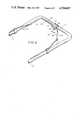
- FIG. 4is a perspective view of a second preferred embodiment of the control assembly of the present invention mounted on a mower handle bar.
- FIG. 1a typical walk-behind self-propelled lawn mower is partially shown generally at 10.
- the mower 10includes a first preferred embodiment of a dual bale mower control assembly of the present invention shown generally at 11.
- the mower 10includes a blade housing 12 for a rotary cutting blade (not shown) driven by the conventional gasoline engine 14. Steering of the mower 10 is accomplished by a handle bar 15 that is attached to the rear of the mower body to extend upwardly and rearwardly therefrom.
- the handle bar 15is formed from two tubular opposite side portions 17 and 18 and a tubular cross portion 19 that extends between and connects the rear ends of the side portions 17 and 18.
- the engine 14is adapted through drive trains and clutch mechanisms (not shown) to serve as the power source for both the mower blade and drive wheels of the mower 10, which drive wheels may either be the front wheels (not shown) or rear wheels 21 of the mower 10.
- the control assembly 11is adapted for mounting from the handle bar 15 to provide for independent actuation of the engine 14 and the drive clutches.
- the control assembly 11includes a pair of bale members 24 and 25 that are a mirror image of one another and are journaled on an axle 26 extending between the side portions 17 and 18 of the handle bar 15.
- the bale members 24 and 25are generally of a U-shaped configuration (as shown in FIG. 2) and each include a partially curved side 27 adjacent one of the handle bar portions 17 or 18, a straight side portion 28 and a transverse rear side 29, all of which sides 27, 28, and 29 form the bale members 24 and 25 in unitary fashion.
- the bale member rear side 29is arcuately-shaped to conform to the tubular configuration of the handle bar cross portion 19.
- the cross portion 19is receivable in the arcuate rear bale side 29 of either of the bale members 24 or 25 when they are moved to their fullest rear position as indicated by bale 24 in FIG. 2.
- the bale members 24 and 25are preferably spring biased in their forward most position by spring assemblies (not shown) associated with cable control means 31 and 32, as are well known in the art, attached respectively to bale members 24 and 25.
- the cable assemblies 31 and 32are connectable respectively to the bales 24 and 25 by means of two vertically spaced apart appertures in the sides 27, and the particular apperture utilized is dependent upon the amount of stroke desired for the bales 24 and 25.
- the bale member 24is associated with the operator zone engine kill/restart and the bale member 25 is associated with the drive clutch.
- bale member 24to be pivoted from its forward most neutral position to its rearward most (actuating) position in which the bale member rear side 29 is adjacent the handle bar cross portion 19.
- the bale members 24 and 25each include a limit of movement abutment prong 33 extending outwardly from the free end of the bale member curved side 27 in orthogonal fashion thereto to ensure that the bale members cannot be pivoted beyond their engagement with the handle bar cross section 19.
- FIG. 4a second preferred embodiment of the control assembly of the present invention is shown generally at 35.
- the operating principle of the assembly 35is identical to that of the assembly 11.
- the assembly 35has bale members 36 and 37 that are of a different shape than the bale members 24 and 25 and are connected in a different fashion to the handle bar 15.
- the bale members 36 and 37are a mirror image of one another and include a tubular-shaped side 38 adjacent one of the handle bar side portions 17 or 18 and a tubular-shaped rear side portion 39.
- the bale members 36 and 37differ from the bale members 24 and 25 by having the side 38 terminating in a prong 40 and a curved truncated side portion 41 that extends only a short distance out from the rear side 39 and has a pronged end 42.
- the bale members 36 and 37are pivotally connected to the handle bar 15 by means of the prongs 40 and 42 on the ends of the sides 38 and 41.
- the prongs 40 and 42extend into corresponding apertures 43 and 44 in the handle bar side portions 17 and 18 and a connecting means 48 to serve as axles for the bale sides 38 and 41.
- the connecting means 42is attached to the medial portion of the handle bar cross portion 19 to pivotally connect the truncated sides 40 of the bale members 36 and 37 to such cross portion.
- the present inventionprovides a dual bale mower control assembly that is relatively simplistic in construction and operation but yet fully and effectively meets all federal regulations for providing dual control of the starting and driving functions of a self-propelled walk-behind mower. Not only is the control assembly of the present invention easy for a user to become familiar with, but moreover, the control assembly can thereafter be used for operating the mower 10 in almost troublefree fashion.
Landscapes
- Life Sciences & Earth Sciences (AREA)
- Environmental Sciences (AREA)
- Physics & Mathematics (AREA)
- General Physics & Mathematics (AREA)
- Engineering & Computer Science (AREA)
- Automation & Control Theory (AREA)
- Harvester Elements (AREA)
Abstract
Description
Claims (4)
Priority Applications (1)
| Application Number | Priority Date | Filing Date | Title |
|---|---|---|---|
| US06/806,531US4704847A (en) | 1985-12-09 | 1985-12-09 | Control mechanism for walk-behind mower |
Applications Claiming Priority (1)
| Application Number | Priority Date | Filing Date | Title |
|---|---|---|---|
| US06/806,531US4704847A (en) | 1985-12-09 | 1985-12-09 | Control mechanism for walk-behind mower |
Publications (1)
| Publication Number | Publication Date |
|---|---|
| US4704847Atrue US4704847A (en) | 1987-11-10 |
Family
ID=25194256
Family Applications (1)
| Application Number | Title | Priority Date | Filing Date |
|---|---|---|---|
| US06/806,531Expired - Fee RelatedUS4704847A (en) | 1985-12-09 | 1985-12-09 | Control mechanism for walk-behind mower |
Country Status (1)
| Country | Link |
|---|---|
| US (1) | US4704847A (en) |
Cited By (25)
| Publication number | Priority date | Publication date | Assignee | Title |
|---|---|---|---|---|
| US4885903A (en)* | 1988-07-27 | 1989-12-12 | Scag Dane T | Safety interlock for lawn mowers |
| EP0419175A1 (en)* | 1989-09-18 | 1991-03-27 | Qualcast Garden Products Ltd. | Improvements in or relating to lawnmowers |
| US5088273A (en)* | 1990-12-21 | 1992-02-18 | Briggs & Stratton Corporation | Lawnmower handle assembly |
| US5146735A (en)* | 1990-06-29 | 1992-09-15 | Fuqua Industries, Inc. | Lawn mower drive and control systems |
| US5261214A (en)* | 1992-08-21 | 1993-11-16 | The Toro Company | Lawn mower bail pivot stop and cable anchor |
| US5343678A (en)* | 1993-02-04 | 1994-09-06 | Ransomes, Inc. | Lawn mower control device |
| US5355662A (en)* | 1993-02-22 | 1994-10-18 | The Toro Company | Single bail self-propel and zone brake control |
| US5601512A (en)* | 1995-10-19 | 1997-02-11 | Snapper, Inc. | Reverse speed control for lawn mowers |
| WO1999021407A1 (en)* | 1997-10-29 | 1999-05-06 | Kamm Michael A | Lawn mower bail |
| US6082083A (en)* | 1998-09-18 | 2000-07-04 | The Toro Company | Ground speed control system |
| US6105348A (en)* | 1998-06-30 | 2000-08-22 | Honda Giken Kogyo Kabushiki Kaisha | Safety cut-off system for use in walk-behind power tool |
| EP1198980A1 (en)* | 2000-10-20 | 2002-04-24 | Ibea S.p.A. | Motor-driven lawn mower |
| EP1285566A1 (en)* | 2001-08-23 | 2003-02-26 | MTD Products, Inc. | Speed control system for a power equipment vehicle |
| US6644002B2 (en) | 2001-09-25 | 2003-11-11 | Deere & Company | Walk-behind self-propelled power equipment unit with speed control |
| US20040093767A1 (en)* | 2002-11-14 | 2004-05-20 | Phillip Thomas E. | Split wireform bail |
| US20050144919A1 (en)* | 2004-01-05 | 2005-07-07 | Honda Motor Co., Ltd. | Variable speed transmission twist-grip throttle control apparatuses and methods for self-propelled mowing machine |
| US20050252185A1 (en)* | 2004-01-05 | 2005-11-17 | Honda Motor Co., Ltd. | Variable speed transmission twist control apparatuses and methods for self-propelled mowing machine |
| WO2006012494A1 (en)* | 2004-07-23 | 2006-02-02 | Briggs & Stratton Power Products Group, Llc | Control assembly for a lawnmower |
| US20060218887A1 (en)* | 2004-06-17 | 2006-10-05 | Honda Motor Co., Ltd. | Apparatuses and methods for controlling self-propelled machines |
| US20090107095A1 (en)* | 2007-10-26 | 2009-04-30 | Scott Kaskawitz | Variable speed transmission adjustable twist control apparatuses and methods for self-propelled mowing machine |
| US7762050B1 (en) | 2009-03-11 | 2010-07-27 | Honda Motor Co., Ltd. | Bail-free machine control devices and methods |
| DE102010044302A1 (en)* | 2010-09-03 | 2012-03-08 | Al-Ko Kober Ag | Drive for garden appliance, has cross bar extending transversely to direction of travel of garden appliance, where cross bar is connected to garden appliance |
| CN103891467A (en)* | 2012-12-31 | 2014-07-02 | 天佑电器(苏州)有限公司 | Gardening tool handle assembly |
| US10709064B2 (en) | 2018-01-31 | 2020-07-14 | The Toro Company | Propulsion control lockout and ground working vehicle incorporating same |
| US20250221342A1 (en)* | 2012-10-15 | 2025-07-10 | Chervon (Hk) Limited | Gardening tool, particularly a mower |
Citations (8)
| Publication number | Priority date | Publication date | Assignee | Title |
|---|---|---|---|---|
| US4212141A (en)* | 1978-02-02 | 1980-07-15 | Honda Giken Kogyo Kabushiki Kaisha | Lawn mower |
| US4221108A (en)* | 1979-05-25 | 1980-09-09 | Owens Boyd L | Lawnmower safety control system |
| US4316355A (en)* | 1979-08-13 | 1982-02-23 | Hoffco, Inc. | Combined flywheel and clutch mechanism for lawn mower blade |
| US4382228A (en)* | 1974-07-15 | 1983-05-03 | Wentworth Laboratories Inc. | Probes for fixed point probe cards |
| US4413466A (en)* | 1982-01-01 | 1983-11-08 | Conchemco, Incorporated | Control assembly for blade clutch unit |
| US4433530A (en)* | 1982-09-23 | 1984-02-28 | Simplicity Manufacturing, Inc. | Interlock mechanism preventing engine starting when a mower is in power drive |
| US4455811A (en)* | 1983-01-20 | 1984-06-26 | Conchemco, Incorporated | Bail attachment lawnmower zone start control |
| US4531347A (en)* | 1983-01-26 | 1985-07-30 | Wolf-Gerate Gmbh | Lawn mower with wheel drive |
- 1985
- 1985-12-09USUS06/806,531patent/US4704847A/ennot_activeExpired - Fee Related
Patent Citations (8)
| Publication number | Priority date | Publication date | Assignee | Title |
|---|---|---|---|---|
| US4382228A (en)* | 1974-07-15 | 1983-05-03 | Wentworth Laboratories Inc. | Probes for fixed point probe cards |
| US4212141A (en)* | 1978-02-02 | 1980-07-15 | Honda Giken Kogyo Kabushiki Kaisha | Lawn mower |
| US4221108A (en)* | 1979-05-25 | 1980-09-09 | Owens Boyd L | Lawnmower safety control system |
| US4316355A (en)* | 1979-08-13 | 1982-02-23 | Hoffco, Inc. | Combined flywheel and clutch mechanism for lawn mower blade |
| US4413466A (en)* | 1982-01-01 | 1983-11-08 | Conchemco, Incorporated | Control assembly for blade clutch unit |
| US4433530A (en)* | 1982-09-23 | 1984-02-28 | Simplicity Manufacturing, Inc. | Interlock mechanism preventing engine starting when a mower is in power drive |
| US4455811A (en)* | 1983-01-20 | 1984-06-26 | Conchemco, Incorporated | Bail attachment lawnmower zone start control |
| US4531347A (en)* | 1983-01-26 | 1985-07-30 | Wolf-Gerate Gmbh | Lawn mower with wheel drive |
Cited By (32)
| Publication number | Priority date | Publication date | Assignee | Title |
|---|---|---|---|---|
| US4885903A (en)* | 1988-07-27 | 1989-12-12 | Scag Dane T | Safety interlock for lawn mowers |
| EP0419175A1 (en)* | 1989-09-18 | 1991-03-27 | Qualcast Garden Products Ltd. | Improvements in or relating to lawnmowers |
| US5146735A (en)* | 1990-06-29 | 1992-09-15 | Fuqua Industries, Inc. | Lawn mower drive and control systems |
| US5088273A (en)* | 1990-12-21 | 1992-02-18 | Briggs & Stratton Corporation | Lawnmower handle assembly |
| US5261214A (en)* | 1992-08-21 | 1993-11-16 | The Toro Company | Lawn mower bail pivot stop and cable anchor |
| US5343678A (en)* | 1993-02-04 | 1994-09-06 | Ransomes, Inc. | Lawn mower control device |
| US5355662A (en)* | 1993-02-22 | 1994-10-18 | The Toro Company | Single bail self-propel and zone brake control |
| US5601512A (en)* | 1995-10-19 | 1997-02-11 | Snapper, Inc. | Reverse speed control for lawn mowers |
| WO1999021407A1 (en)* | 1997-10-29 | 1999-05-06 | Kamm Michael A | Lawn mower bail |
| US6105348A (en)* | 1998-06-30 | 2000-08-22 | Honda Giken Kogyo Kabushiki Kaisha | Safety cut-off system for use in walk-behind power tool |
| US6082083A (en)* | 1998-09-18 | 2000-07-04 | The Toro Company | Ground speed control system |
| EP1198980A1 (en)* | 2000-10-20 | 2002-04-24 | Ibea S.p.A. | Motor-driven lawn mower |
| EP1285566A1 (en)* | 2001-08-23 | 2003-02-26 | MTD Products, Inc. | Speed control system for a power equipment vehicle |
| US6644002B2 (en) | 2001-09-25 | 2003-11-11 | Deere & Company | Walk-behind self-propelled power equipment unit with speed control |
| US20040093767A1 (en)* | 2002-11-14 | 2004-05-20 | Phillip Thomas E. | Split wireform bail |
| US6745548B1 (en) | 2002-11-14 | 2004-06-08 | Ariens Company | Split wireform bail |
| US20050144919A1 (en)* | 2004-01-05 | 2005-07-07 | Honda Motor Co., Ltd. | Variable speed transmission twist-grip throttle control apparatuses and methods for self-propelled mowing machine |
| US20050252185A1 (en)* | 2004-01-05 | 2005-11-17 | Honda Motor Co., Ltd. | Variable speed transmission twist control apparatuses and methods for self-propelled mowing machine |
| US7318309B2 (en) | 2004-01-05 | 2008-01-15 | Honda Motor Co., Ltd | Variable speed transmission twist control apparatuses and methods for self-propelled mowing machine |
| US20080047246A1 (en)* | 2004-01-05 | 2008-02-28 | Osborne Christopher M | Variable speed transmission twist-grip throttle control apparatuses and methods for self-propelled mowing machine |
| US20060218887A1 (en)* | 2004-06-17 | 2006-10-05 | Honda Motor Co., Ltd. | Apparatuses and methods for controlling self-propelled machines |
| US7293397B2 (en) | 2004-06-17 | 2007-11-13 | Honda Motor Co., Ltd. | Apparatuses and methods for controlling self-propelled machines |
| WO2006012494A1 (en)* | 2004-07-23 | 2006-02-02 | Briggs & Stratton Power Products Group, Llc | Control assembly for a lawnmower |
| US20090107095A1 (en)* | 2007-10-26 | 2009-04-30 | Scott Kaskawitz | Variable speed transmission adjustable twist control apparatuses and methods for self-propelled mowing machine |
| US7543429B2 (en) | 2007-10-26 | 2009-06-09 | Honda Motor Co., Ltd. | Variable speed transmission adjustable twist control apparatuses and methods for self-propelled mowing machine |
| US7762050B1 (en) | 2009-03-11 | 2010-07-27 | Honda Motor Co., Ltd. | Bail-free machine control devices and methods |
| DE102010044302A1 (en)* | 2010-09-03 | 2012-03-08 | Al-Ko Kober Ag | Drive for garden appliance, has cross bar extending transversely to direction of travel of garden appliance, where cross bar is connected to garden appliance |
| DE102010044302B4 (en)* | 2010-09-03 | 2014-12-11 | Al-Ko Kober Ges. M.B.H | Handle for a gardening tool and gardening tool |
| US20250221342A1 (en)* | 2012-10-15 | 2025-07-10 | Chervon (Hk) Limited | Gardening tool, particularly a mower |
| CN103891467A (en)* | 2012-12-31 | 2014-07-02 | 天佑电器(苏州)有限公司 | Gardening tool handle assembly |
| US10709064B2 (en) | 2018-01-31 | 2020-07-14 | The Toro Company | Propulsion control lockout and ground working vehicle incorporating same |
| US11013173B2 (en) | 2018-01-31 | 2021-05-25 | The Toro Company | Propulsion control lockout and ground working vehicle incorporating same |
Similar Documents
| Publication | Publication Date | Title |
|---|---|---|
| US4704847A (en) | Control mechanism for walk-behind mower | |
| US3757500A (en) | Multiple unit lawnmower construction | |
| US4335566A (en) | Control system for power equipment | |
| US6109010A (en) | Mowing vehicle control system | |
| US5261214A (en) | Lawn mower bail pivot stop and cable anchor | |
| US5146735A (en) | Lawn mower drive and control systems | |
| US6557331B2 (en) | Operator control system for self-propelled vehicles | |
| US7624996B2 (en) | Walk-behind lawn mower sulky latch assembly | |
| US5896931A (en) | Convertible garden tiller | |
| AU2011360270B2 (en) | Handle control arrangement of a walk-behind lawn mower | |
| EP3515169B1 (en) | Control assembly for a walk-behind mower | |
| US4538401A (en) | Control lever assembly in a self-propelled lawn mower | |
| US5297379A (en) | Walk-behind lawn mower with front wheel steering | |
| US4281732A (en) | Two-stage deadman control for walk-behind mower | |
| US20050145421A1 (en) | Lawn mower having selectively drivable wheels | |
| US7762050B1 (en) | Bail-free machine control devices and methods | |
| US7647754B2 (en) | Walk behind lawn mower control system | |
| US4493180A (en) | Lawn mower dead man control | |
| JP3897913B2 (en) | Riding lawn mower | |
| US4744580A (en) | Tow hitch for a tractor | |
| US5509258A (en) | Operator presence control for reel mower | |
| US7553248B2 (en) | Belt drive system incorporating fixed brake member | |
| US4760687A (en) | Mower deck height and clutch control | |
| US6708472B2 (en) | Lawn mower having disabling feature | |
| US6237311B1 (en) | Reverse mowing prevention device |
Legal Events
| Date | Code | Title | Description |
|---|---|---|---|
| AS | Assignment | Owner name:WESTERN INTERNATIONAL, INC., 3811 MCDONALD AVENUE, Free format text:ASSIGNMENT OF ASSIGNORS INTEREST.;ASSIGNORS:GREIDER, C. AUSTIN;BERRY, TIMOTHY E.;REEL/FRAME:004492/0986 Effective date:19851122 | |
| FEPP | Fee payment procedure | Free format text:PAT HLDR NO LONGER CLAIMS SMALL ENT STAT AS INDIV INVENTOR (ORIGINAL EVENT CODE: LSM1); ENTITY STATUS OF PATENT OWNER: LARGE ENTITY | |
| FPAY | Fee payment | Year of fee payment:4 | |
| FEPP | Fee payment procedure | Free format text:PAYOR NUMBER ASSIGNED (ORIGINAL EVENT CODE: ASPN); ENTITY STATUS OF PATENT OWNER: LARGE ENTITY | |
| FPAY | Fee payment | Year of fee payment:8 | |
| AS | Assignment | Owner name:MURRAY, INC., TENNESSEE Free format text:MERGER AND CHANGE OF NAME;ASSIGNORS:NOMA INDUSTRIES;NOMA OUTDOOR PRODUCTS, INC.;WESTERN INTERNATIONAL INCORPORATED;AND OTHERS;REEL/FRAME:007666/0694 Effective date:19870908 | |
| FEPP | Fee payment procedure | Free format text:PAYER NUMBER DE-ASSIGNED (ORIGINAL EVENT CODE: RMPN); ENTITY STATUS OF PATENT OWNER: LARGE ENTITY Free format text:PAYOR NUMBER ASSIGNED (ORIGINAL EVENT CODE: ASPN); ENTITY STATUS OF PATENT OWNER: LARGE ENTITY | |
| REMI | Maintenance fee reminder mailed | ||
| LAPS | Lapse for failure to pay maintenance fees | ||
| FP | Lapsed due to failure to pay maintenance fee | Effective date:19991110 | |
| AS | Assignment | Owner name:GENERAL ELECTRIC CAPITAL CORPORATION, AS AGENT, IL Free format text:SECURITY AGREEMENT;ASSIGNOR:MURRAY, INC.;REEL/FRAME:011333/0036 Effective date:20001005 | |
| STCH | Information on status: patent discontinuation | Free format text:PATENT EXPIRED DUE TO NONPAYMENT OF MAINTENANCE FEES UNDER 37 CFR 1.362 |