US4703573A - Visual and audible activated work and method of forming same - Google Patents
Visual and audible activated work and method of forming sameDownload PDFInfo
- Publication number
- US4703573A US4703573AUS06/698,161US69816185AUS4703573AUS 4703573 AUS4703573 AUS 4703573AUS 69816185 AUS69816185 AUS 69816185AUS 4703573 AUS4703573 AUS 4703573A
- Authority
- US
- United States
- Prior art keywords
- visual
- pages
- sound
- activation state
- work
- Prior art date
- Legal status (The legal status is an assumption and is not a legal conclusion. Google has not performed a legal analysis and makes no representation as to the accuracy of the status listed.)
- Expired - Lifetime
Links
Images


Classifications
- G—PHYSICS
- G09—EDUCATION; CRYPTOGRAPHY; DISPLAY; ADVERTISING; SEALS
- G09B—EDUCATIONAL OR DEMONSTRATION APPLIANCES; APPLIANCES FOR TEACHING, OR COMMUNICATING WITH, THE BLIND, DEAF OR MUTE; MODELS; PLANETARIA; GLOBES; MAPS; DIAGRAMS
- G09B5/00—Electrically-operated educational appliances
- G09B5/06—Electrically-operated educational appliances with both visual and audible presentation of the material to be studied
- G09B5/062—Combinations of audio and printed presentations, e.g. magnetically striped cards, talking books, magnetic tapes with printed texts thereon
- A—HUMAN NECESSITIES
- A63—SPORTS; GAMES; AMUSEMENTS
- A63F—CARD, BOARD, OR ROULETTE GAMES; INDOOR GAMES USING SMALL MOVING PLAYING BODIES; VIDEO GAMES; GAMES NOT OTHERWISE PROVIDED FOR
- A63F13/00—Video games, i.e. games using an electronically generated display having two or more dimensions
- A63F13/25—Output arrangements for video game devices
- A63F13/26—Output arrangements for video game devices having at least one additional display device, e.g. on the game controller or outside a game booth
- A—HUMAN NECESSITIES
- A63—SPORTS; GAMES; AMUSEMENTS
- A63F—CARD, BOARD, OR ROULETTE GAMES; INDOOR GAMES USING SMALL MOVING PLAYING BODIES; VIDEO GAMES; GAMES NOT OTHERWISE PROVIDED FOR
- A63F13/00—Video games, i.e. games using an electronically generated display having two or more dimensions
- A63F13/50—Controlling the output signals based on the game progress
- A63F13/54—Controlling the output signals based on the game progress involving acoustic signals, e.g. for simulating revolutions per minute [RPM] dependent engine sounds in a driving game or reverberation against a virtual wall
- A—HUMAN NECESSITIES
- A63—SPORTS; GAMES; AMUSEMENTS
- A63F—CARD, BOARD, OR ROULETTE GAMES; INDOOR GAMES USING SMALL MOVING PLAYING BODIES; VIDEO GAMES; GAMES NOT OTHERWISE PROVIDED FOR
- A63F13/00—Video games, i.e. games using an electronically generated display having two or more dimensions
- A63F13/90—Constructional details or arrangements of video game devices not provided for in groups A63F13/20 or A63F13/25, e.g. housing, wiring, connections or cabinets
- A63F13/92—Video game devices specially adapted to be hand-held while playing
- A—HUMAN NECESSITIES
- A63—SPORTS; GAMES; AMUSEMENTS
- A63H—TOYS, e.g. TOPS, DOLLS, HOOPS OR BUILDING BLOCKS
- A63H33/00—Other toys
- A63H33/38—Picture books with additional toy effects, e.g. pop-up or slide displays
- A—HUMAN NECESSITIES
- A63—SPORTS; GAMES; AMUSEMENTS
- A63H—TOYS, e.g. TOPS, DOLLS, HOOPS OR BUILDING BLOCKS
- A63H5/00—Musical or noise- producing devices for additional toy effects other than acoustical
- B—PERFORMING OPERATIONS; TRANSPORTING
- B42—BOOKBINDING; ALBUMS; FILES; SPECIAL PRINTED MATTER
- B42D—BOOKS; BOOK COVERS; LOOSE LEAVES; PRINTED MATTER CHARACTERISED BY IDENTIFICATION OR SECURITY FEATURES; PRINTED MATTER OF SPECIAL FORMAT OR STYLE NOT OTHERWISE PROVIDED FOR; DEVICES FOR USE THEREWITH AND NOT OTHERWISE PROVIDED FOR; MOVABLE-STRIP WRITING OR READING APPARATUS
- B42D1/00—Books or other bound products
- B42D1/003—Books or other bound products characterised by shape or material of the sheets
- B42D1/007—Sheets or sheet blocks combined with other articles
- B—PERFORMING OPERATIONS; TRANSPORTING
- B42—BOOKBINDING; ALBUMS; FILES; SPECIAL PRINTED MATTER
- B42D—BOOKS; BOOK COVERS; LOOSE LEAVES; PRINTED MATTER CHARACTERISED BY IDENTIFICATION OR SECURITY FEATURES; PRINTED MATTER OF SPECIAL FORMAT OR STYLE NOT OTHERWISE PROVIDED FOR; DEVICES FOR USE THEREWITH AND NOT OTHERWISE PROVIDED FOR; MOVABLE-STRIP WRITING OR READING APPARATUS
- B42D15/00—Printed matter of special format or style not otherwise provided for
- B42D15/02—Postcards; Greeting, menu, business or like cards; Letter cards or letter-sheets
- B42D15/022—Postcards; Greeting, menu, business or like cards; Letter cards or letter-sheets combined with permanently fastened sound-producing or light-emitting means or carrying sound records
- G—PHYSICS
- G06—COMPUTING OR CALCULATING; COUNTING
- G06F—ELECTRIC DIGITAL DATA PROCESSING
- G06F3/00—Input arrangements for transferring data to be processed into a form capable of being handled by the computer; Output arrangements for transferring data from processing unit to output unit, e.g. interface arrangements
- G06F3/14—Digital output to display device ; Cooperation and interconnection of the display device with other functional units
- G06F3/1423—Digital output to display device ; Cooperation and interconnection of the display device with other functional units controlling a plurality of local displays, e.g. CRT and flat panel display
- G—PHYSICS
- G09—EDUCATION; CRYPTOGRAPHY; DISPLAY; ADVERTISING; SEALS
- G09F—DISPLAYING; ADVERTISING; SIGNS; LABELS OR NAME-PLATES; SEALS
- G09F25/00—Audible advertising
- G—PHYSICS
- G09—EDUCATION; CRYPTOGRAPHY; DISPLAY; ADVERTISING; SEALS
- G09F—DISPLAYING; ADVERTISING; SIGNS; LABELS OR NAME-PLATES; SEALS
- G09F27/00—Combined visual and audible advertising or displaying, e.g. for public address
- G—PHYSICS
- G09—EDUCATION; CRYPTOGRAPHY; DISPLAY; ADVERTISING; SEALS
- G09F—DISPLAYING; ADVERTISING; SIGNS; LABELS OR NAME-PLATES; SEALS
- G09F9/00—Indicating arrangements for variable information in which the information is built-up on a support by selection or combination of individual elements
- G09F9/30—Indicating arrangements for variable information in which the information is built-up on a support by selection or combination of individual elements in which the desired character or characters are formed by combining individual elements
- G09F9/301—Indicating arrangements for variable information in which the information is built-up on a support by selection or combination of individual elements in which the desired character or characters are formed by combining individual elements flexible foldable or roll-able electronic displays, e.g. thin LCD, OLED
- G—PHYSICS
- G09—EDUCATION; CRYPTOGRAPHY; DISPLAY; ADVERTISING; SEALS
- G09G—ARRANGEMENTS OR CIRCUITS FOR CONTROL OF INDICATING DEVICES USING STATIC MEANS TO PRESENT VARIABLE INFORMATION
- G09G3/00—Control arrangements or circuits, of interest only in connection with visual indicators other than cathode-ray tubes
- G09G3/20—Control arrangements or circuits, of interest only in connection with visual indicators other than cathode-ray tubes for presentation of an assembly of a number of characters, e.g. a page, by composing the assembly by combination of individual elements arranged in a matrix no fixed position being assigned to or needed to be assigned to the individual characters or partial characters
- G09G3/34—Control arrangements or circuits, of interest only in connection with visual indicators other than cathode-ray tubes for presentation of an assembly of a number of characters, e.g. a page, by composing the assembly by combination of individual elements arranged in a matrix no fixed position being assigned to or needed to be assigned to the individual characters or partial characters by control of light from an independent source
- G09G3/36—Control arrangements or circuits, of interest only in connection with visual indicators other than cathode-ray tubes for presentation of an assembly of a number of characters, e.g. a page, by composing the assembly by combination of individual elements arranged in a matrix no fixed position being assigned to or needed to be assigned to the individual characters or partial characters by control of light from an independent source using liquid crystals
- G09G3/3611—Control of matrices with row and column drivers
- G09G3/3696—Generation of voltages supplied to electrode drivers
- G—PHYSICS
- G09—EDUCATION; CRYPTOGRAPHY; DISPLAY; ADVERTISING; SEALS
- G09G—ARRANGEMENTS OR CIRCUITS FOR CONTROL OF INDICATING DEVICES USING STATIC MEANS TO PRESENT VARIABLE INFORMATION
- G09G3/00—Control arrangements or circuits, of interest only in connection with visual indicators other than cathode-ray tubes
- G09G3/20—Control arrangements or circuits, of interest only in connection with visual indicators other than cathode-ray tubes for presentation of an assembly of a number of characters, e.g. a page, by composing the assembly by combination of individual elements arranged in a matrix no fixed position being assigned to or needed to be assigned to the individual characters or partial characters
- G09G3/34—Control arrangements or circuits, of interest only in connection with visual indicators other than cathode-ray tubes for presentation of an assembly of a number of characters, e.g. a page, by composing the assembly by combination of individual elements arranged in a matrix no fixed position being assigned to or needed to be assigned to the individual characters or partial characters by control of light from an independent source
- G09G3/38—Control arrangements or circuits, of interest only in connection with visual indicators other than cathode-ray tubes for presentation of an assembly of a number of characters, e.g. a page, by composing the assembly by combination of individual elements arranged in a matrix no fixed position being assigned to or needed to be assigned to the individual characters or partial characters by control of light from an independent source using electrochromic devices
- G—PHYSICS
- G10—MUSICAL INSTRUMENTS; ACOUSTICS
- G10L—SPEECH ANALYSIS TECHNIQUES OR SPEECH SYNTHESIS; SPEECH RECOGNITION; SPEECH OR VOICE PROCESSING TECHNIQUES; SPEECH OR AUDIO CODING OR DECODING
- G10L13/00—Speech synthesis; Text to speech systems
- B—PERFORMING OPERATIONS; TRANSPORTING
- B44—DECORATIVE ARTS
- B44F—SPECIAL DESIGNS OR PICTURES
- B44F1/00—Designs or pictures characterised by special or unusual light effects
- B44F1/08—Designs or pictures characterised by special or unusual light effects characterised by colour effects
- B44F1/10—Changing, amusing, or secret pictures
- G—PHYSICS
- G02—OPTICS
- G02F—OPTICAL DEVICES OR ARRANGEMENTS FOR THE CONTROL OF LIGHT BY MODIFICATION OF THE OPTICAL PROPERTIES OF THE MEDIA OF THE ELEMENTS INVOLVED THEREIN; NON-LINEAR OPTICS; FREQUENCY-CHANGING OF LIGHT; OPTICAL LOGIC ELEMENTS; OPTICAL ANALOGUE/DIGITAL CONVERTERS
- G02F1/00—Devices or arrangements for the control of the intensity, colour, phase, polarisation or direction of light arriving from an independent light source, e.g. switching, gating or modulating; Non-linear optics
- G02F1/01—Devices or arrangements for the control of the intensity, colour, phase, polarisation or direction of light arriving from an independent light source, e.g. switching, gating or modulating; Non-linear optics for the control of the intensity, phase, polarisation or colour
- G02F1/13—Devices or arrangements for the control of the intensity, colour, phase, polarisation or direction of light arriving from an independent light source, e.g. switching, gating or modulating; Non-linear optics for the control of the intensity, phase, polarisation or colour based on liquid crystals, e.g. single liquid crystal display cells
- G02F1/133—Constructional arrangements; Operation of liquid crystal cells; Circuit arrangements
- G02F1/13306—Circuit arrangements or driving methods for the control of single liquid crystal cells
- G02F1/13324—Circuits comprising solar cells
- G—PHYSICS
- G02—OPTICS
- G02F—OPTICAL DEVICES OR ARRANGEMENTS FOR THE CONTROL OF LIGHT BY MODIFICATION OF THE OPTICAL PROPERTIES OF THE MEDIA OF THE ELEMENTS INVOLVED THEREIN; NON-LINEAR OPTICS; FREQUENCY-CHANGING OF LIGHT; OPTICAL LOGIC ELEMENTS; OPTICAL ANALOGUE/DIGITAL CONVERTERS
- G02F1/00—Devices or arrangements for the control of the intensity, colour, phase, polarisation or direction of light arriving from an independent light source, e.g. switching, gating or modulating; Non-linear optics
- G02F1/01—Devices or arrangements for the control of the intensity, colour, phase, polarisation or direction of light arriving from an independent light source, e.g. switching, gating or modulating; Non-linear optics for the control of the intensity, phase, polarisation or colour
- G02F1/13—Devices or arrangements for the control of the intensity, colour, phase, polarisation or direction of light arriving from an independent light source, e.g. switching, gating or modulating; Non-linear optics for the control of the intensity, phase, polarisation or colour based on liquid crystals, e.g. single liquid crystal display cells
- G02F1/133—Constructional arrangements; Operation of liquid crystal cells; Circuit arrangements
- G02F1/1333—Constructional arrangements; Manufacturing methods
- G—PHYSICS
- G02—OPTICS
- G02F—OPTICAL DEVICES OR ARRANGEMENTS FOR THE CONTROL OF LIGHT BY MODIFICATION OF THE OPTICAL PROPERTIES OF THE MEDIA OF THE ELEMENTS INVOLVED THEREIN; NON-LINEAR OPTICS; FREQUENCY-CHANGING OF LIGHT; OPTICAL LOGIC ELEMENTS; OPTICAL ANALOGUE/DIGITAL CONVERTERS
- G02F1/00—Devices or arrangements for the control of the intensity, colour, phase, polarisation or direction of light arriving from an independent light source, e.g. switching, gating or modulating; Non-linear optics
- G02F1/01—Devices or arrangements for the control of the intensity, colour, phase, polarisation or direction of light arriving from an independent light source, e.g. switching, gating or modulating; Non-linear optics for the control of the intensity, phase, polarisation or colour
- G02F1/15—Devices or arrangements for the control of the intensity, colour, phase, polarisation or direction of light arriving from an independent light source, e.g. switching, gating or modulating; Non-linear optics for the control of the intensity, phase, polarisation or colour based on an electrochromic effect
- G02F1/163—Operation of electrochromic cells, e.g. electrodeposition cells; Circuit arrangements therefor
Definitions
- the present inventionrelates to a novel and unique visual and audible activated work such as a child's book or a greeting card having at least two turnable pages in juxtaposed relationship and which is formed having a visual display thereof that is essentially invisible in a first state but visible in a second state and a sound synthesizer which is inactive during said first state and actively generates sound during said second state.
- Electrical signalsare coupled to the visual display and sound synthesizer for selectively and reversibly changing the visual display from the invisible to the visible state and the sound synthesizer from the inactive to sound generating state when the pages are moved from their juxtaposed relationship.
- persistent electrochromic materialis defined as a material responsive to the application of an electric field of a given polarity to change from a first persistent state in which it is essentially non-absorptive of electromagnetic radiation in a given wave length region to a second persistent state in which it is absorptive of electromagnetic radiation in the given wave length region and once in said second state is responsive to the application of an electric field of the opposite polarity to return to its first state.
- Certain of such materialscan also be responsive to a short circuiting condition, in the absence of an electric field, so as to return to the initial state.
- persistentis meant the ability of the material to remain in the absorptive state to which it is changed after removal of the electric field as distinguished from a substantially instantaneous reversion to the initial state.
- the devicefunctions by applying an EMF to the electrodes to cause coloration or a visible display of the electrochromic layer receiving the applied EMF.
- the colored electrochromic layerwill be uncolored (erased or made invisible) by the reverse flow of current.
- the filmwill be persistent in either its colored (visible) state or its non-colored (invisible) state without the need for a continuous current or EMF to maintain the state. See also U.S. Pat. No. 4,344,674.
- liquid crystalswork in a similar manner wherein liquid crystals used in displays are not optically active but instead change their light scattering characteristics when a voltage is applied across a liquid crystal film between two closely spaced conductive sheets. With no applied voltage, the crystalline structure is orderly and the material is clear and invisible; with voltage applied, the light is scattered and the layer becomes opaque and visible.
- Liquid crystalshave been classified into three categories: nematic, cholesteric and smectic.
- the nematic and cholesteric phasesare liquid which have optical properties.
- the optical absorption spectrum of a pleochroic dye moleculeis a function of its molecular orientation with respect to the polarization of the incident light.
- the dye moleculeIf the dye molecule is oriented with its long axis parallel to the electric vector of incident polarized light, absorption of the light by the molecule occurs, and an observer sees the characteristic color of the dye. Conversely, if the dye molecules have their long axis perpendicular to the electric vector, little or no absorption occurs and the incident light is transmitted unchanged.
- Nematic compoundshave a strong dipole moment on the molecule's main axis and thus orient dye molecules in color switching devices. Such electronic color switching relies on the introduction of dyes composed of pleochroic molecules. To orient the dye with respect to the field to produce the desired color changes requires the use of a nematic liquid crystal that has different properties than the type used for dynamic scattering.
- the nematic material to which the dye is addedmust have an extremely strong dipole moment operating along the long axis of the molecules instead of one operating at an angle with this axis. When a voltage is applied, this moment will align with the field. This causes the dye molecules to also align with the field resulting in the disappearance of the color of the dye.
- Another examplemay be a tree which at first has nothing on it but later has apples appearing on it. Still later, the apples could be made to disappear from the tree and appear on the ground.
- Another examplecould be a running animal formed from a series or sequence of pictures which appear and disappear to cause the animal to appear to be running across the page.
- one portion of the cardcould be a visible picture or message and when the card is opened, a second display or message could be made visible.
- the second messagecould be made to appear at one time or letter by letter in sequential succession.
- a good example of a speech synthesizer chipis the TMS5100 which was developed by Texas Instruments for educational uses.
- the electronic circuit contained on a semiconductor chipproduces electrical impulses convertable into simulated human speech with an electronically activated speaker electrically connected to the semiconductor chip for receiving said electrical impulses and converting them into sound simulating human speech.
- Speech synthesis techniquesper se, are old and well known in the art as disclosed by Gene A. Frantz et al, Design case history: Speak & Spell learns to talk, IEEE Spectrum,February 1982, pp. 45-49 and Eve J. Lerner, Products That Talk, IEEE Spectrum, July 1982, pp. 32-37. Using such techniques with the present invention adds the sense of hearing to the sense of sight to give added perception to learning and added meaning to a sentimentality.
- a picture of an animal such as a catcould have added the letters C, A and T appearing in sequence and, as each letter appears, the speech synthesizer circuit would sequentially produce the sounds of the letters C, A and T in conjunction with the sequential appearance of the letters.
- a messagecould appear, either in its entirety in conjunction with the vocal presentation of the message or the message could appear letter by letter with the voice articulating each word as the letters are sequentially spelled. For instance the entire message "I LOVE YOU” could be made to appear simultaneously with the sounds of the words. In like manner, the message could be made to appear one letter at a time with the voice speaking at the end of each word.
- the voice repeats "YOU"After the word "YOU" has been spelled, the voice repeats "YOU”. Then the voice could repeat the entire message: I LOVE YOU.
- an activated bookcomprising at least two turnable pages pivotally attached at one edge of each of said pages so that said pages are pivotable from a juxtaposed closed position to an adjacent open position; a visual image display means affixed to one of said pages, said visual image display having a first visual activation state at which a visual image is not visible thereon and a second visual activation state at which a visual image is visible thereon; a sound generating means attached to said book having a first activation state at which an audible sound is not generated and a second activation state at which an audible sound is generated; means connected to said visual display means for selectively activating said visual display means from one of said visual activation states to another upon pivoting said pages from said closed position to said opened position or from said opened position to said closed position; and means connected to said sound generating means for selectively activating said sound generating means from one of said sound activation states to another upon pivoting said pages from said closed position to said opened position or from said opened position to said closed position; and means connected to said sound
- FIG. 1is a diagrammatic representation of a work, preferably a child's book, having a section removed to indicate the pages under the cover;
- FIG. 2is a diagrammatic representation of the work of FIG. 1 in its open condition showing text on the left side and a first scene on the opposite page and circuitry coupled to the first scene which could be utilized to cause a second scene to appear and disappear and a speech synthesizer for producing speech relating to said scene when it appears;
- FIG. 3Ais a diagrammatic representation of the open work in FIG. 2 after the second scene is caused to appear showing apples on a tree and a figure in a cave entrance and an animal under the tree and illustrating the synthesized speech relating to the tree, the figure and the animal;
- FIG. 3Bis a schematic representation of the open work of FIG. 3A in which the figure has moved from the cave entrance, the apples are now lying under the tree, and the animal is moving across the page and illustrating synthesized speech relating to the animal;
- FIG. 4Ais a cross sectional representation of the power supply in FIG. 2 illustrating the use of a solar cell as the power source;
- FIG. 4Bis also a cross sectional view of the power supply in FIG. 2 illustrating the use of a battery as the power supply and having a cover thereon and a switch which is operable by opening or closing the work to activate or deactivate the battery;
- FIG. 5is a schematic representation of a power supply coupled to series connected heating elements to heat the material which is invisible to form a visible scene;
- FIG. 6is a schematic representation of the heating elements for the scene to be made visible coupled in parallel to the power supply
- FIG. 7is a diagrammatic representation of a circuit coupling the power supply to the visual display to cause it to appear or disappear and to the speech synthesizer;
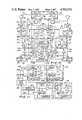
- FIG. 8is a detailed circuit drawing of the schematic representation shown in FIG. 7;
- FIG. 9is a schematic representation of a circuit for changing the scene and/or producing a voice by touching a capacitive switch located on a page of the work;
- FIG. 10is a detailed circuit diagram of the basic circuit shown in FIG. 9 to cause a change of the display and/or the speech by touching a capacitive switch on a page of the work;
- FIG. 11is a schematic representation of a circuit necessary to cause an object such as an animal to move across the page in a sequence of pictures and/or to cause a sequence of sounds;
- FIG. 12is a schematic circuit diagram of an alternate embodiment of the circuit for driving a display and/or a speech synthesizer with alternate polarity voltages to cause the display to first be in the invisible state and then to change to the visible state and/or to cause the speech synthesizer to change from a silent state to an audible state;
- FIG. 13is a circuit diagram of the manner in which a phototransistor may be used in the ground circuit of the power supply to cause the power supply to be operative when the pages of the work are turned or circumstances are such that light can strike the phototransistor;
- FIG. 14is an alternate embodiment of a circuit diagram for driving two displays wherein both displays are first driven to the invisible state and speech synthesizers are driven to a silent state, the first display is then driven to the visible state and the speech synthesizer is driven to an audible state, and upon operation of a touch switch, the first display is driven back to the invisible state and the sound is silent, and the second display is simultaneously driven to the visible state and the speech synthesizer is driven to an audible state;
- FIG. 15is an alternate embodiment of the invention illustrating an activated work such as a greeting card wherein the individual letters of an invisible message are visibly spelled out sequentially upon the opening of the card while simultaneously the speech synthesizer repeats the words or letters printed;
- FIG. 16is a schematic diagram of a circuit which can be used to cause the letters of the message and/or the synthesized speech in the greeting card of FIG. 15 to appear and be produced sequentially;
- FIG. 17is a circuit diagram illustrating a circuit which could be used as a capacitive touch switch to cause a first display to become invisible and a second display to become visible or to cause speech to be produced;
- FIG. 18is a circuit diagram of a clock that can be used in the circuit of FIG. 16;
- FIG. 19is a circuit diagram of a reset monostable multivibrator which can be used as the reset circuit in FIG. 16;
- FIG. 20is a circuit diagram of a flip flop that can be used in the circuit of FIG. 16.
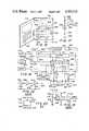
- FIG. 1is a diagrammatic representation of a work of the present invention such as a book, the book being generally designated by the numeral 10 and having an upper page or cover 12 and at least one or more lower pages 14.
- FIG. 2illustrates the book of FIG. 1 in its open position showing the left side of the book having writing 16 or text thereon and on the right side 14 a first scene including mountains 17, a cave entrance 18 in mountains 17 and a tree 20.
- the scenecould be of any type and, as shown, is illustrative only and is presented for discussion of the manner in which the novel invention functions and is not intended to be limiting in scope.
- Power supply 22which may be any power supply and preferably a portable power supply such as a battery or a solar cell, is coupled through connections 24 to a control circuit 26 which produces an output on line 28 that is coupled to a visual image display means such as either a liquid crystal or an electrochromic display forming at least a portion of a visual image.
- a visual image display meanssuch as either a liquid crystal or an electrochromic display forming at least a portion of a visual image.
- the displayis of both the cave entrance 18 and tree 20 and which circuit 26 produces an output on line 29 that is coupled to a speech synthesizer 31 whose output is coupled to a sound producing means 21 such as a speaker or sound disc.
- a switch 30,such as a capacitive touch switch or any other miniature switch which can be operated manually, is shown having an output on connection 32 coupled to control circuit 26 which can force a current to be produced on line 28 coupled to the displays forming at least a portion of both cave entrance 18 and tree 20 to cause a scene to change.
- the cave entrance 18may, for example, be empty when the book is first opened.
- the tree 20may be barren except for leaves.
- the power supply 22will produce a voltage which is coupled by the circuits described earlier in relation to FIG. 2 to the displays forming at least a portion of cave 18 and to the tree 20.
- the displaysnow form a second scene that is interposed with the first scene including a FIG. 34 which has appeared in the entrance of cave 18, apples 36 which have appeared on tree 20 and/or the figure of an animal 38 which has appeared underneath tree 20. This is caused, as explained earlier, by either a voltage produced by power supply 22 being coupled to a photochromic material or a liquid crystal display or heat generated by the current produced by power supply 22 and applied to a liquid crystal material.
- the speech synthesizer circuit 31will cause speaker 21 to utter a phrase or words related to the figure such as, for example only, "cave man” as indicated at 35.
- the synthesizer 31may cause speaker 21 to utter the word "apples” as indicated at 37.
- the speech synthesizer 31may cause speaker 21 to utter the word "cat” as indicated at 39.
- a fingeris merely placed in contact with a switch such as capacitive touch switch 30 which causes the control circuit to reverse the voltage polarity or to remove the heat to change the second scene shown in FIG. 3A causing it to go blank and, if desired, causing a third scene to appear as shown in FIG. 3B.
- a switchsuch as capacitive touch switch 30 which causes the control circuit to reverse the voltage polarity or to remove the heat to change the second scene shown in FIG. 3A causing it to go blank and, if desired, causing a third scene to appear as shown in FIG. 3B.
- the figure or individual 34has stepped out of the mouth of cave 18, at least part of the apples 36 have fallen from the tree and now lie on the ground, and the animal 38 is now moving across the page in a sequence of pictures 40, 42, and 44.
- the speech synthesizer 31may cause the speaker 21 to utter some words related to the figure or the animal or the apples such as, for example only, as related to the animal, "see the cat run” as indicated at 41, "what does a cat say” as indicated at 43, and/or "meow” as indicated at 45.
- a display 47may be placed on the page of the book and the letters CAT, for example only, may spell out the name of the animal as the voice spells the letters in conjunction with the letters appearing.
- the book 10 shown in FIG. 2could be a greeting card 318 as shown in FIG. 15 having the solar cell 322 powering displays 328 which may be, for instance, a single or multiple LCD or electrochromic displays.
- the act of opening of the card 318would allow the solar cell to produce power to the display 328 which could then provide a textual or other visual and oral message or pictorial display to the person opening the card.
- the messagewould be preprogrammed into a semiconductor chip in a well known manner with an appropriate delay line 166 as shown in FIG. 11 to cause a small delay after the card is opened before the message appears.
- the circuitcan cause the textual message to appear one letter at a time. In that case, the circuit shown in FIG.
- the first SET circuit 160would cause the first letter of the message to be printed at display 164 in FIG. 11 and after an appropriate delay caused by delay circuit 166, the next SET circuit 173 could cause the next letter of the textual message to appear and so forth until the entire textual message has been printed.
- the displayneed not be in colors other than black and white and thus a liquid crystal without other colors than black and white could be used.
- the electrochromic material or heat sensitive liquid crystalproviding colored letters in addition to black and white could also be used if desired.
- an oral message or another appropriate vocal soundsuch as that of a kiss could be generated.
- FIG. 4Ais a cross sectional view of the power supply 22 shown in FIG. 2 and is comprised of a solar cell 22 that is mounted in the page 14 when it is formed.
- the solar cell 22will, of course, only produce a voltage when it receives light.
- FIG. 3A or FIG. 3Blight striking photocell 22 will cause a voltage to be produced which will generate the first scene shown in FIG. 3A.
- FIG. 4Bis a cross sectional view of an alternate form of a power supply as shown in FIG. 1 which is a battery 46 mounted in page 14 and held in place by a cover 48.
- a switch 50may be formed in the page 14 of the book in any well known manner to connect the battery 46 to the circuit when the book is opened and disconnect the battery 46 from the circuits when the pages are closed. As will be explained hereafter in relation to FIG. 13, this switch may be a phototransistor in the ground circuit of the power supply to enable the power supply only when the page is turned and light strikes the phototransistor.
- FIG. 5is a circuit diagram illustrating how the LCD elements, which are affected by and change colors other than black and white under the influence of heat, are energized.
- power supply 52which may be either the battery 46 in FIG. 4B or the solar cell 22 in FIG. 4A, energizes heating elements 54 which are shown in series to cause a temperature rise at each of the element 54 locations thus causing the LCD associated with each of the heating elements 54 to change its state from one color to another as explained previously.
- Switch 50is shown in FIG. 5 to represent a switch which is opened and closed by the turning of the page in the event that power supply 52 is a battery 52.
- This switchcould be any known electrical switching device such as a mechanical switch that is spring loaded or could be the phototransistor 232 in FIG. 13. When the power supply is a solar cell, no switch 50 is required. When the power is removed and the elements 54 cool, the second scene disappears.
- FIG. 6is identical to FIG. 5 except in this case the switch 50 is not shown and the heating elements are connected in parallel rather than in series. However, the circuit functions otherwise in exactly the same way as described earlier with respect to FIG. 5.
- FIG. 7illustrates the basic electrical block diagram for control of the novel system.
- Power supply 22which may be either a solar cell or a battery, supplies output voltage on lines 55 and 57 which are coupled to control network 56 and switch 58.
- the switch 58first applies a first polarity voltage on lines 55 and 57 to the load 60 on respective lines 64 and 66. This voltage serves to cause the display 62, which may be the individual figure in cave 18 in FIGS. 3A or 3B or the apples 36 on tree 20 or on the ground or animal 38, to be in the nonvisible state.
- control network 56After the display has been forced to its nonvisible state, control network 56 then causes switch 58 to reverse the voltage polarity applied to load 60 or display 62 which then causes the display to become visible as discussed earlier thus causing the individual 34 to appear in cave 18 or apples 36 to appear on tree 20 or to be on the ground underneath the tree or the animal 38 to appear. It further activates speech synthesizer 67 to cause the proper voice to appear in conjunction with the activated display 62.
- FIG. 8is a detailed schematic diagram of the circuitry shown in block diagram in FIG. 7.
- power supply 22may be comprised of solar cells 68 and 70 (or batteries) with a center tapped ground connection 72. Since the output of each of the solar cells is fed through an identical circuit, only one of the circuits will be described in detail.
- the output of solar cell 68is coupled on line 74 to an amplifier 76. When the book is first opened, the solar cells begin to produce a voltage output. This voltage is coupled to amplifier 76 which at some point in the rise of the voltage will produce an output on lines 78 and 80.
- the signal or voltage on line 80is coupled to an AND gate 82 as one input.
- the output of the amplifier 76 on line 78is coupled to a pulse generator 84 that produces a voltage spike output on line 86 to one-shot multivibrator 88.
- one-shot multivibrator 88when it receives the pulse on line 86, will temporarily change states thus producing an output on line 90 so long as one-shot multivibrator 88 stays in its switched position.
- the inverter 92which has the signal on line 90 as an input, has no output on line 94 thus disabling AND gate 82.
- the output signal from one-shot multivibrator 88 on line 90is also coupled to amplifier 96 which produces a positive polarity output on line 98 to display 100. Since the output from solar cell 70 has gone through exactly the same procedure in a similar circuit except to produce a negative polarity voltage, a voltage of polarity from plus to minus is applied across display 100 thus forcing it into the invisible state.
- one-shot multivibrator 88 on line 90decays, no signal is present on line 90 and thus amplifier 96 fails to provide the positive polarity input on line 98 to display 100.
- Inverter 92now produces an output on line 94 enabling AND gate 82 which causes a positive voltage to now be coupled on line 83 to the other side of the display and in a similar manner the output of AND gate 102 causes the negative voltage on line 104 to be applied to the opposite side of display 100 thus causing the text or pictorial display to appear as described earlier.
- speech synthesizer 80is activated in conjunction with the display 100.
- circuitrywhen the book 10 is closed that the solar cells will no longer receive light and will no longer produce a voltage output and the circuit will become inoperative. However, as soon as the book is opened again and the solar cells again produce voltage, the circuitry will operate as described previously to drive the display to the nonvisible condition so long as one-shot multivibrator produces a pulse on line 90 and then will revert to the visible state causing the picture or scene and the associated voice to again appear.
- the circuitrymay be constructed of MOS/LSI circuits which are low power, large scale integrated circuits using metal oxide semiconductor devices.
- FIG. 9illustrates the manner in which the second scene can be made invisible and a third scene made to appear as for example the apples in FIG. 3B dropping from tree 20 onto the ground.
- the capacitive touch switch 30 in FIG. 9, and as shown in FIGS. 2, 3A and 3B,will be activated when the user of the book places a finger in proximity to switch 30.
- An outputwill be produced on line 106 to a control network 108 which resets the first display 111 representing the second scene to the nonvisible condition by a signal on line 110 and produces a signal on line 112 to set the second display 114 representing the third scene to the visible condition.
- the voice circuit 113is simultaneously activated.
- FIG. 10the circuitry above dashed line 116 operates in the manner previously discussed in relation to FIG. 8 to initially clear displays 111 and 114 and then to reverse the voltage to display 111 causing the second scene to appear.
- the output from one-shot multivibrator 88 on line 90is coupled to amplifier 97 that produces the outupt on line 99 to drive display 111 to the nonvisible condition or state.
- that signal on line 90is also coupled to amplifier 116 which produces an output on line 118 to reset or drive display 114 to the nonvisible state.
- AND gate 82produces an output on line 83 to AND gates 120, 122 and 124.
- bi-stable multivibrator 126has been SET by the pulse on line 90 from one-shot multivibrator 88 and it produces no output signal on line 128.
- AND gate 120to be disabled and it produces no output on line 142.
- AND gate 122 from the other circuitis also disabled so that it produces no output.
- bi-stable multivibrator 126has been SET and no output appears on line 128, bi-stable multivibrator 130 stays in its SET state with no output on line 132 and thus AND gate 124 is also disabled.
- both displays 111 and 114have had voltage applied to them with a polarity to force them to the nonvisible state.
- inverter 134will produce an output on line 136 thus enabling AND gate 122 and causing the negative voltage output from AND gate 102 to be applied on line 104 to AND gate 122 which will produce a negative voltage output on line 140 to display 111.
- AND gate 122 on the negative side of the circuitwill be enabled thus applying the positive voltage from AND gate 82 on line 83 to the display 111 thus driving it to the visible state to form the second scene shown in FIG. 3A.
- Speech synthesizer 123may then be activated to produce a voice associated with the second scene such as the word "apples".
- the output signal on line 128 from multivibrator 126is coupled to multivibrator 130 which is caused to produce an enabling signal on line 132 to AND gate 124.
- the other input to AND gate 124 on line 144is the negative voltage from AND gate 102 which enables AND gate 124 to produce a negative voltage signal on output line 146 thus enabling or driving display 114 to the visible state and activating voice circuit 147. Since display 111 represented the individual or FIG. 34 in the cave, apples 36 on the tree, or animal 38 this means that the FIG. 34 is now made invisible in the cave entrance and the apples 36 on the tree and animal 38 are made invisible by driving display 111 in the reverse direction. However, since display 114 represents individual or FIG.
- the novel inventionprovides for a first scene as shown in FIG. 2 which is fixed, a second scene as shown in FIG. 3A interposed with the first scene whereby certain portions are caused to appear and a third scene is caused to appear and the second scene disappear as shown in FIG. 3B.
- a voicemay be associated with each scene. This is accomplished by the circuit shown in detail in FIG. 10.
- FIG. 11discloses the basic block diagram of a circuit which can be utilized to cause, for example only, an animal 38 shown in FIG. 3A to move across the page as illustrated by the dashed FIGS. 40, 42 and 44 in FIG. 3B by activating capacitive touch switch 30.
- the output signal generated by capacitive touch switch 30 on line 107is coupled to OR gate 148 which produces an output on line 149 to a circuit 150 which is identical to the circuits 152, 154 and 156 which follow thereafter.
- OR gate 148which produces an output on line 149 to a circuit 150 which is identical to the circuits 152, 154 and 156 which follow thereafter.
- more than four circuitscould be coupled in series as shown but only four such circuits are shown here for purposes of clarity of description and ease of illustration.
- the successive setting and clearing of the particular displayscauses the animal 38 to successively appear and disappear and gives the impression as shown in FIG. 2B that the animal or other object is moving across the page.
- the speed at which it will movedepends upon the delay time of the delay circuits such as 166 and 176.
- This circuitmay also be used to spell a sentence, phrase or word letter by letter with the voice circuit sounding each letter as it appears. If the word spelled is CAT, when the signal on line 162 causes display 164 to print "C", voice circuit 164 audibly states “C”. The same operation occurs with the outputs from the other circuits where shown in FIG. 11. When the last letter is printed, the signal on line 183 may cause the voice circuit 163 to sound the word such as, for example, "CAT".
- FIG. 12is a circuit diagram of an alternate embodiment of a circuit which could be used to cause a display to go from the invisible to the visible state.
- solar cells 190 and 192provide the power source. They are center tapped by ground circuit 194 and the output of solar cell 192 on line 196 is coupled to PNP transistor 198 while the output of solar cell 190 on line 200 is coupled to NPN transistor 202. The output of solar cell 192 is also coupled on line 204 to one-shot multivibrator 206.
- one-shot multivibrator 206 on line 208is coupled to the base 210 of NPN transistor 202 thus turning transistor 202 on and allowing the negative voltage from solar cell 200 to pass through the emitter and collector of transistor 202 to the display 212 on line 214.
- Resistor 216serves as the return ground path. Thus, a voltage from negative to ground is applied across the display 212 thus driving it to the invisible condition.
- one-shot multivibrator 206 on line 208is coupled to an inverter 218 which, during the time a signal is present on line 208 from one-shot multivibrator 206, does not have an output on line 220 and thus AND gate 222 is disabled.
- inverter 218produces an output on line 220 which enables AND gate 222 thus coupling the negative voltage on line 200 from solar cell 190 to the speech synthesizer 223 to activate it and to the base 224 of PNP transistor 198 thus turning it on.
- FIG. 13is a circuit diagram of a portion of a circuit which can be used if batteries replace solar cells 190 and 192 in FIG. 12.
- batteries 226 and 228are coupled together at their opposite polarity terminals by line 230 and a phototransistor 232 is coupled between line 230 and ground 234.
- the output of the batteries 226 and 228 on lines 236 and 238respectively would be coupled to the circuit in FIG. 12 as if they were the outputs of the solar cells 190 and 192. It can be seen that when no light strikes phototransistor 232, it is an open circuit thus preventing any current flow from the batteries through the ground circuit shown in FIG.
- FIG. 14is an alternate embodiment of a circuit which can be used to control two displays and two speech synthesizers wherein the first display and voice and the second display and voice are driven to the invisible and silent state and then the first display and voice is driven to the visible and audible state.
- a touch switchcan be operated and the first display and voice is driven again to the invisible and silent state while the second display is driven to the visible and audible state.
- the circuitoperates as follows. Again the power sources 240 and 242 may be either solar cells or batteries as desired. Their opposite output polarities are center tapped at 244 and coupled to ground 246. In addition, the output of power supply 240 on line 248 is coupled to the collectors of NPN transistors 250 and 252 as well as to AND gates 254 and 256. In like manner, the positive output voltage on line 258 from power supply 242 is coupled to the emitters of PNP transistors 260 and 262 as well as to one-shot vibrator 264, AND gate 266, and AND gate 268.
- both power suppliesproduce output voltages.
- Power supply 240produces a negative voltage on line 248 and power supply 242 produces a positive voltage on line 258.
- one-shot multivibrator 264produces an output on line 270 which is coupled to a bi-stable multivibrator 272 through connection 274, inverter 276 and the base 278 of transistor 250.
- This signalcauses transistor 250 to conduct thus coupling the negative supply voltage on line 248 through the emitter and collector of transistor 250 to one side of display 280 thus driving display 280 to the invisible state by applying a voltage to it which is negative with respect to ground potential.
- one-shot multivibrator 264 on line 274causes bi-stable multivibrator 272 to SET and it produces an output on line 282 which is coupled to AND gate 284 and AND gate 268 as an enabling signal.
- AND gate 284, which is coupled to base 286 of transistor 260does not have the other enabling signal coupled into it and thus it is disabled at that moment.
- AND gate 268is enabled because of the positive voltage appearing on line 288 and thus AND gate 268 produces an output on line 290 which is coupled to the base 292 of transistor 252 thus causing it to conduct and the negative voltage on line 248 flows through the emitter and collector of transistor 252 on line 294 to display 295 thus driving it also to the invisible state.
- transistor 250When the pulse from one-shot multivibrator 264 decays, transistor 250 is disabled and stops conducting. At the same time, inverter 276 now produces an output on line 296 which enables AND gate 254 to conduct and cause a negative voltage on line 298 to be coupled as the other enabling input to AND gate 284. AND gate 284 now produces an output on line 300 which is coupled to the base 286 of transistor 260 thus turning this transistor on and causing it to conduct. When transistor 260 conducts, it couples the positive voltage on line 258 through its emitter and collector and produces an output on line 302 to display 280 thus placing a positive to ground voltage across the display and driving it to the visible state as well as activating voice circuit 279.
- AND gate 266is now enabled with the signal on line 308 thus producing an output to the base 278 of transistor 250 thus causing it to conduct once again and it couples the negative voltage on line 248 across display 280 to ground thus driving that display to the invisible state once again.
- bi-stable multivibrator 272 on line 308is coupled through line 310 to AND gate 256 to enable it and it produces a negative voltage on output line 312 to the base 314 of transistor 262 thus causing it to conduct. It therefore conducts the positive voltage on line 258 through its emitter and collector on line 316 to second display 295 thus driving it to the visible state and enabling voice circuit 317.
- this circuitprovides an alternate means for controlling two displays and causing each one to be able to go reversibly from the visible to the invisible state and to activate the appropriate voice circuit 279 or 317 when display 280 or 295 is activated and the scene made visible.
- FIG. 15is an alternate embodiment of an activated work which can be utilized by this invention.
- a worksuch as a greeting card 318 is illustrated having some writing or pictures depicted at 320 on one of the inside sheets and having on the other sheet and embedded therein a power supply 322 with a phototransistor 324 in its ground path as illustrated previously with respect to FIG. 13.
- the greeting card 318is opened and light strikes the phototransistor 324, it activates power supply 322 which is coupled to a control circuit 326 which drives a display formed of sequential segments 328 to cause letters of a message to appear. This may be done either simultaneously or sequentially. Thus, if simultaneously, the words "I love you" could appear for example.
- a voice circuit 327is activated to cause speaker 329 to state "I love you".
- the messagewould begin with the letter I, followed by the letter L, O and so forth until the message has been spelled out.
- voice circuit 327would cause the letters to be individually spoken as they appear. Obviously, this is an example only and many other types of messages could be displayed either having segments of the message caused to appear sequentially or having the entire message or pictorial representation or depiction appear instantaneously with a corresponding voice pattern.
- FIG. 16illustrates a circuit which could be used to activate or operate the novel card shown in FIG. 15 wherein the message letters and accompanying voice would appear sequentially.
- the display 330is comprised of either a single display or a number of individual segments 332, 334, 336 and 338. It will, of course, be realized that the number of segments that are desired to be used could be any number
- power supply 340produces outputs to enable clock 342 and reset circuit 344, Reset circuit 344 produces an output on line 346 which is coupled to both counter 352 and flip flops 354 to clear them.
- One flip flop 354is provided for each of the display segments 332 through 338.
- the flip flops 354are all reset or cleared such that an output is produced on line 358 and coupled to an inverter 360 which produces the proper output polarity on line 362 to drive segment 338, for instance, to the invisible state. That output signal from inverter 360 is also coupled on line 364 to AND gate 366.
- AND gate 366to produce an output on line 368 which is a clock enable signal coupled to counter 352 through AND gate 380.
- the clock 342is running all the time and producing clock pulses on line 370 to counter 352.
- counter 352will not operate until the enable signal appears on line 368.
- the counter 352begins to count and the first count removes the signal on line 356 to AND gate 366 thus removing the clock enable signal to the counter 352.
- the clock enable pulse on line 368is removed, it is also coupled to flip flop 372 to clear it, and no output is produced on line 374 from flip flop 372.
- inverter 376This causes inverter 376 to produce an output on line 378 which is coupled through AND gate 380 as the clock enable signal to counter 352 enabling it to continue to count after the signal on line 368 is removed.
- the counter 352reaches the end of its count and all of the flip flops 354 have been set, the counter 352 returns to its initial state thus again producing an output on line 356.
- the inverter 360now does not have an output on line 364 and thus AND gate 366 is not enabled and no clock enable appears on line 368.
- the signal on line 356 from counter 352is coupled to flip flop 372 to SET it thus producing an output on line 374 which removes the output from inverter 376 and killing the clock enable signal on line 378 to AND gate 380 and removing the clock enable signal to counter 352.
- the counting stops and the messageis visible on the individual segments of display 330 because flip flops 354 have been individually set.
- Speech circuit 339was also activated as each display segment was activated and thus each letter was sounded as it appeared. As indicated earlier these segments may be individual letters of a message. Also, they may be individual depictions of some type as, for instance, a picture.
- the display 330is intended to include any type that can be constructed with the liquid crystal displays and photochromic displays encompassed herein.
- the entire circuitryWhen the card is closed and the power supply is disabled, the entire circuitry then is ready to be driven to its reset state by reset circuit 344 whenever the card is opened once again and the message repeats itself. It will be understood that in the reset state the flip flops 354 are all driven such as to clear the elements of display 330. It is when the counter begins to count that each of the flip flops are set and cause an output through the inverters 360 which drive each individual segment to its visible state.
- FIG. 17is a circuit diagram of a capacitive touch switch which can be of MOS/LSI construction and which can be used as the switch 304 in FIG. 14.
- inverter 382is coupled between a resistor 384 and a capacitive switch 386.
- the voltage from source 388is coupled through resistor 384 to the input of inverter 382.
- no output signalappears on line 390.
- the bodycauses a resistance 392 to ground 394. This resistance 392 is small compared to resistor 384 and is represented by dashed lines.
- inverter 282may be of the type manufactured by National Semiconductor Corporation and known as MM54C04. These are the same type of inverters that may be used in any of the other circuits herein such as those in FIG. 16 and designated as inverters 360 and 376.
- FIG. 18is a schematic representation of a clock circuit which can be used as clock 342 in FIG. 16.
- inverters 396, 398 and 400are coupled in series to an output terminal 402.
- the input to inverter 396 and the output of inverter 400are coupled together through series connected resistors 404 and 406.
- a capacitor 408couples the output of inverter 398 to the junction of resistors 404 and 406.
- the frequency of the output pulses from this clockwill depend upon the values of capacitor 408 and resistors 404 and 406.
- the inverters 396, 398 and 400may be of the type previously designated as MM54C04 and may be of MOS/LSI construction.
- FIG. 19is a circuit diagram of the reset circuit 344 shown in FIG. 16 and is in effect a monostable multivibrator.
- FETgeneral purpose field effect transistor
- the operational amplifier 412may be of the type well known in the art and designated as CM3900.
- the general purpose FET 420may also be of any well known general purpose type. The size of capacitor 416 and resistor 420 will create a time constant which will determine how long the reset pulse will appear on line 414.
- FIG. 20discloses the schematic representation of a bi-stable multivibrator or flip flop such as those which are designated in FIG. 16 as flip flops 354 and 372.
- flip flop 424has a voltage input on line 426, a set pulse on line 428, a clear pulse on line 430 and an output signal on line 432.
- the output on line 432would be a signal which may be designated as Q and in the other state would have no signal which would be designated as Q.
- the flip flop 424has a set pulse applied to it a signal or Q signal will appear on line 432 whereas when the clear pulse is applied to line 430, no signal or the Q signal will appear on line 432.
- This type of flip flopis also well known in the art and is designated as the National Semiconductor Corporation flip flop MM54C74.
- the circuits used hereinmay be monolithic MOS integrated circuits and general purpose FET transistors may also be used. These circuits consume low power and can be very densely packed in a tiny space thus meeting the conditions required for use in an activated work such as a child's book or greeting card.
- a novel book and in particular a child's bookhaving at least one colored picture of a scene to be viewed, a second scene interposed with the first scene and being essentially invisible in a first deactivated state and visible in a second activated state and an electrical source for selectively and reversibly changing the second scene from the invisible to the visible state and to generate an appropriate voice with each visible state of a scene.
- the inventionalso contemplates a third scene interposed with said first scene and being essentially invisible in a first state and visible in a second state with means for deactivating or making the second scene invisible and the third scene visible along with an audible, appropriate voice message.
Landscapes
- Engineering & Computer Science (AREA)
- Multimedia (AREA)
- Physics & Mathematics (AREA)
- Theoretical Computer Science (AREA)
- General Physics & Mathematics (AREA)
- Business, Economics & Management (AREA)
- Educational Technology (AREA)
- Educational Administration (AREA)
- Acoustics & Sound (AREA)
- Human Computer Interaction (AREA)
- Computer Hardware Design (AREA)
- General Engineering & Computer Science (AREA)
- Chemical & Material Sciences (AREA)
- Crystallography & Structural Chemistry (AREA)
- Computational Linguistics (AREA)
- Health & Medical Sciences (AREA)
- Audiology, Speech & Language Pathology (AREA)
- Devices For Indicating Variable Information By Combining Individual Elements (AREA)
Abstract
Description
The present invention relates to a novel and unique visual and audible activated work such as a child's book or a greeting card having at least two turnable pages in juxtaposed relationship and which is formed having a visual display thereof that is essentially invisible in a first state but visible in a second state and a sound synthesizer which is inactive during said first state and actively generates sound during said second state. Electrical signals are coupled to the visual display and sound synthesizer for selectively and reversibly changing the visual display from the invisible to the visible state and the sound synthesizer from the inactive to sound generating state when the pages are moved from their juxtaposed relationship.
There exists in the state of the art electro-optical devices exhibiting a phenomenon known as persistent electrochromism wherein electromagnetic radiation absorption characteristics of a persistent electrochromic material are altered under the influence of an electric field. Such devices are employed in sandwich arrangement between two electrodes. Coloration is induced by charging the electrochromic field negative with respect to the counter electrode which can be the same as the persistent electrochromic material or different. By reversing the original polarity of the field or by applying a new field it is possible to cancel, erase or bleach the visible coloration. These steps of color induction and erasure are defined as cycling. As described in U.S. Pat. No. 3,978,007, persistent electrochromic material is defined as a material responsive to the application of an electric field of a given polarity to change from a first persistent state in which it is essentially non-absorptive of electromagnetic radiation in a given wave length region to a second persistent state in which it is absorptive of electromagnetic radiation in the given wave length region and once in said second state is responsive to the application of an electric field of the opposite polarity to return to its first state. Certain of such materials can also be responsive to a short circuiting condition, in the absence of an electric field, so as to return to the initial state. Further, by "persistent" is meant the ability of the material to remain in the absorptive state to which it is changed after removal of the electric field as distinguished from a substantially instantaneous reversion to the initial state.
Thus, in this case, the device functions by applying an EMF to the electrodes to cause coloration or a visible display of the electrochromic layer receiving the applied EMF. By reversing the polarity of the two electrodes and applying an EMF, the colored electrochromic layer will be uncolored (erased or made invisible) by the reverse flow of current. The film will be persistent in either its colored (visible) state or its non-colored (invisible) state without the need for a continuous current or EMF to maintain the state. See also U.S. Pat. No. 4,344,674.
As stated in U.S. Pat. No. 4,174,152 the exact mechanism of persistent electrochromism is unknown but the coloration is observed to occur at the negatively charged electrochromic layer. Generally, the phenomenon of persistent electrochromism is believed to involve transport of cations, such as hydrogen or lithium ions, to the negative electrode where color centers form in the electrochromic image layer as a result of charged compensating electron flow. As stated in the prior patents, voltages of less than two volts d.c. applied to the layers of the electrochromic material will bring about the color change and reversal. Thus, the devices require very little current or power to operate and yet can be effectively colored (made visible) and discolored (made invisible) by the reversal of the small voltage potential to the material.
It is also known that liquid crystals work in a similar manner wherein liquid crystals used in displays are not optically active but instead change their light scattering characteristics when a voltage is applied across a liquid crystal film between two closely spaced conductive sheets. With no applied voltage, the crystalline structure is orderly and the material is clear and invisible; with voltage applied, the light is scattered and the layer becomes opaque and visible. Liquid crystals have been classified into three categories: nematic, cholesteric and smectic. The nematic and cholesteric phases are liquid which have optical properties. The optical absorption spectrum of a pleochroic dye molecule is a function of its molecular orientation with respect to the polarization of the incident light. If the dye molecule is oriented with its long axis parallel to the electric vector of incident polarized light, absorption of the light by the molecule occurs, and an observer sees the characteristic color of the dye. Conversely, if the dye molecules have their long axis perpendicular to the electric vector, little or no absorption occurs and the incident light is transmitted unchanged.
Nematic compounds have a strong dipole moment on the molecule's main axis and thus orient dye molecules in color switching devices. Such electronic color switching relies on the introduction of dyes composed of pleochroic molecules. To orient the dye with respect to the field to produce the desired color changes requires the use of a nematic liquid crystal that has different properties than the type used for dynamic scattering. The nematic material to which the dye is added must have an extremely strong dipole moment operating along the long axis of the molecules instead of one operating at an angle with this axis. When a voltage is applied, this moment will align with the field. This causes the dye molecules to also align with the field resulting in the disappearance of the color of the dye. Removal of the voltage collapses the field; the nematic host molecules with their dye guest realign in their original configuration and the cell returns to its original color. See Joseph A. Castellano, "Now That The Heat Is Off, Liquid Crystals Can Show Their Colors Everywhere", Electronics, pages 64-69, July 6, 1970. See also "The Bulletin of Arthur D. Little, Inc., No. 488, March-April, 1971.
Further, it is well known that one of the most striking transformations of the optical properties of the cholesteric phase of liquid crystals are those due to temperature changes. Although cholesteric materials are substantially colorless in the isotropic liquid phase, when they are cooled through their clearing temperatures, some pass through a series of colors as viewed in reflected light. Some change only from red to green on cooling; others change from red to green to blue or from red to green and back to red; some are initially blue and change to green and then red. The most remarkable property is that each color corresponds to an exact temperature of the cholesteric material. The rate of color change, the temperature at which specific colors occur and the direction of shift are predictable. See James L. Ferguson et al, "Liquid Crystals And Their Applications" Electro-Technology,page 41, January, 1970.
These phenomena are discussed in U.S. patent application Ser. No. 553,102 for Activated Work and Method for Forming Same, in connection with an activated work, such as a book, pamphlet, greeting card and the like, which has at least one portion formed of electrochromic or liquid crystal material and being essentially invisible in its first deactivated state and visible in a second activated state. A power supply is coupled to the material for selectively activating or deactivating the material and causing said portion to be visible or invisible. Thus, if a book had a page with a picture of a mountain having a cave entrance, one could cause a figure to appear in the mouth of the cave. At a desired time later, the figure could be caused to disappear from the cave entrance again. Another example may be a tree which at first has nothing on it but later has apples appearing on it. Still later, the apples could be made to disappear from the tree and appear on the ground. Another example could be a running animal formed from a series or sequence of pictures which appear and disappear to cause the animal to appear to be running across the page.
In a greeting card, one portion of the card could be a visible picture or message and when the card is opened, a second display or message could be made visible. The second message could be made to appear at one time or letter by letter in sequential succession.
While the invention disclosed in U.S. patent application Ser. No. 553,102 filed Nov. 17, 1983 is extremely useful, it can be used better as a teaching aid with the use of speech synthesis devices which can be constructed to operate in conjunction with the formation of pictures such as letters in order to improve learning capabilities. For instance, whenever a picture of a cat is shown and the corresponding letter C is presented the voice may state "C", when the A is presented, the voice can indicate "A", and when the letter T appears, the voice can state "T" and then, of course, the entire word "CAT" could be voiced by the synthesizer. Speech synthesis, the production of intelligible speech from computer data, is no longer a novelty. Speech chips are available with limited vocabulary at a quality level comparable to that of tape recorders. They can create phrases from 200 or 300 preselected words. Many different companies have developed and marketed speech chips. A good example of a speech synthesizer chip is the TMS5100 which was developed by Texas Instruments for educational uses. The electronic circuit contained on a semiconductor chip produces electrical impulses convertable into simulated human speech with an electronically activated speaker electrically connected to the semiconductor chip for receiving said electrical impulses and converting them into sound simulating human speech.
Further, by using speech synthesis in conjunction with the message being made visible learning could be reinforced or a message made more attractive. Speech synthesis techniques, per se, are old and well known in the art as disclosed by Gene A. Frantz et al, Design case history: Speak & Spell learns to talk, IEEE Spectrum,February 1982, pp. 45-49 and Eve J. Lerner, Products That Talk, IEEE Spectrum, July 1982, pp. 32-37. Using such techniques with the present invention adds the sense of hearing to the sense of sight to give added perception to learning and added meaning to a sentimentality. Thus, a picture of an animal such as a cat could have added the letters C, A and T appearing in sequence and, as each letter appears, the speech synthesizer circuit would sequentially produce the sounds of the letters C, A and T in conjunction with the sequential appearance of the letters. In a card, when opened, a message could appear, either in its entirety in conjunction with the vocal presentation of the message or the message could appear letter by letter with the voice articulating each word as the letters are sequentially spelled. For instance the entire message "I LOVE YOU" could be made to appear simultaneously with the sounds of the words. In like manner, the message could be made to appear one letter at a time with the voice speaking at the end of each word. Thus, after the letter "I" appears, the voice repeats "I". After the word "LOVE" has been spelled the voice repeats "LOVE". After the word "YOU" has been spelled, the voice repeats "YOU". Then the voice could repeat the entire message: I LOVE YOU.
Thus, it is an object of the present invention to provide a voice circuit coordinated with a visual presentation so that the voice reinforces the visual presentation.
It is a further object of the present invention to provide a book having a first scene that is visible and a second scene that is invisible in a first state and visible in a second state and a voice circuit for producing a sound representing the second scene when said second scene is made visible.
It is also an object of the present invention to provide a card or activated work having a message or pictorial representation made visible upon opening of said card or activated work and a voice circuit for producing a speech in coordination with the appearance of the message or pictorial representation.
Thus, it is an object of the present invention to provide an activated book comprising at least two turnable pages pivotally attached at one edge of each of said pages so that said pages are pivotable from a juxtaposed closed position to an adjacent open position; a visual image display means affixed to one of said pages, said visual image display having a first visual activation state at which a visual image is not visible thereon and a second visual activation state at which a visual image is visible thereon; a sound generating means attached to said book having a first activation state at which an audible sound is not generated and a second activation state at which an audible sound is generated; means connected to said visual display means for selectively activating said visual display means from one of said visual activation states to another upon pivoting said pages from said closed position to said opened position or from said opened position to said closed position; and means connected to said sound generating means for selectively activating said sound generating means from one of said sound activation states to another upon pivoting said pages from said closed position to said opened position or from said opened position to said closed position.
It is also an object of the present invention to provide a power source forming said means for selectively activating said sound generating means, and means for energizing said power source whenever the preceding pages turn to its open position and de-energizing said power source whenever the preceding page is returned to its closed position.
It is still another object of the present invention to provide an activated book wherein said sound generating means comprises an electronic speech synthesizer.
It is still another object of the present invention to provide an activated work having at least two turnable pages in juxtapose relationship and having on the inside a first fixed scene to be viewed and a second scene interposed with said first scene and that is essentially invisible in a first state and is visible in a second state, alphabet letters related to said invisible scene which are invisible in a first state and visible in a second state, a speech synthesizer and means coupled to said visual work such that when said pages are moved from their juxtaposed relationship, said invisible scene becomes visible, said invisible letters associated with said scene become visible and said speech synthesizer produces sounds representing the alphabet letters as they are generated.
These and other more detailed objects and advantages of the present invention will be seen in relation to the accompanying drawings in which:
FIG. 1 is a diagrammatic representation of a work, preferably a child's book, having a section removed to indicate the pages under the cover;
FIG. 2 is a diagrammatic representation of the work of FIG. 1 in its open condition showing text on the left side and a first scene on the opposite page and circuitry coupled to the first scene which could be utilized to cause a second scene to appear and disappear and a speech synthesizer for producing speech relating to said scene when it appears;
FIG. 3A is a diagrammatic representation of the open work in FIG. 2 after the second scene is caused to appear showing apples on a tree and a figure in a cave entrance and an animal under the tree and illustrating the synthesized speech relating to the tree, the figure and the animal;
FIG. 3B is a schematic representation of the open work of FIG. 3A in which the figure has moved from the cave entrance, the apples are now lying under the tree, and the animal is moving across the page and illustrating synthesized speech relating to the animal;
FIG. 4A is a cross sectional representation of the power supply in FIG. 2 illustrating the use of a solar cell as the power source;
FIG. 4B is also a cross sectional view of the power supply in FIG. 2 illustrating the use of a battery as the power supply and having a cover thereon and a switch which is operable by opening or closing the work to activate or deactivate the battery;
FIG. 5 is a schematic representation of a power supply coupled to series connected heating elements to heat the material which is invisible to form a visible scene;
FIG. 6 is a schematic representation of the heating elements for the scene to be made visible coupled in parallel to the power supply;
FIG. 7 is a diagrammatic representation of a circuit coupling the power supply to the visual display to cause it to appear or disappear and to the speech synthesizer;
FIG. 8 is a detailed circuit drawing of the schematic representation shown in FIG. 7;
FIG. 9 is a schematic representation of a circuit for changing the scene and/or producing a voice by touching a capacitive switch located on a page of the work;
FIG. 10 is a detailed circuit diagram of the basic circuit shown in FIG. 9 to cause a change of the display and/or the speech by touching a capacitive switch on a page of the work;
FIG. 11 is a schematic representation of a circuit necessary to cause an object such as an animal to move across the page in a sequence of pictures and/or to cause a sequence of sounds;
FIG. 12 is a schematic circuit diagram of an alternate embodiment of the circuit for driving a display and/or a speech synthesizer with alternate polarity voltages to cause the display to first be in the invisible state and then to change to the visible state and/or to cause the speech synthesizer to change from a silent state to an audible state;
FIG. 13 is a circuit diagram of the manner in which a phototransistor may be used in the ground circuit of the power supply to cause the power supply to be operative when the pages of the work are turned or circumstances are such that light can strike the phototransistor;
FIG. 14 is an alternate embodiment of a circuit diagram for driving two displays wherein both displays are first driven to the invisible state and speech synthesizers are driven to a silent state, the first display is then driven to the visible state and the speech synthesizer is driven to an audible state, and upon operation of a touch switch, the first display is driven back to the invisible state and the sound is silent, and the second display is simultaneously driven to the visible state and the speech synthesizer is driven to an audible state;
FIG. 15 is an alternate embodiment of the invention illustrating an activated work such as a greeting card wherein the individual letters of an invisible message are visibly spelled out sequentially upon the opening of the card while simultaneously the speech synthesizer repeats the words or letters printed;
FIG. 16 is a schematic diagram of a circuit which can be used to cause the letters of the message and/or the synthesized speech in the greeting card of FIG. 15 to appear and be produced sequentially;
FIG. 17 is a circuit diagram illustrating a circuit which could be used as a capacitive touch switch to cause a first display to become invisible and a second display to become visible or to cause speech to be produced;
FIG. 18 is a circuit diagram of a clock that can be used in the circuit of FIG. 16;
FIG. 19 is a circuit diagram of a reset monostable multivibrator which can be used as the reset circuit in FIG. 16; and
FIG. 20 is a circuit diagram of a flip flop that can be used in the circuit of FIG. 16.
While the instant invention is applicable to a wide variety of works such as books, pamphlets, games, greeting cards and the like on which it is desired to have words and/or pictorial material visually depicted and/or the words of songs sung, and/or simulated vocal sounds projected, it will be described in connection with books.
FIG. 1 is a diagrammatic representation of a work of the present invention such as a book, the book being generally designated by the numeral 10 and having an upper page or cover 12 and at least one or morelower pages 14.
FIG. 2 illustrates the book of FIG. 1 in its open position showing the left side of the book having writing 16 or text thereon and on the right side 14 a firstscene including mountains 17, acave entrance 18 inmountains 17 and atree 20. The scene, of course, could be of any type and, as shown, is illustrative only and is presented for discussion of the manner in which the novel invention functions and is not intended to be limiting in scope.
Referring now to FIG. 3A, it can be seen that upon opening of the book, thepower supply 22 will produce a voltage which is coupled by the circuits described earlier in relation to FIG. 2 to the displays forming at least a portion ofcave 18 and to thetree 20. It will now be noted that the displays now form a second scene that is interposed with the first scene including a FIG. 34 which has appeared in the entrance ofcave 18,apples 36 which have appeared ontree 20 and/or the figure of ananimal 38 which has appeared underneathtree 20. This is caused, as explained earlier, by either a voltage produced bypower supply 22 being coupled to a photochromic material or a liquid crystal display or heat generated by the current produced bypower supply 22 and applied to a liquid crystal material.
As indicated earlier, when the FIG. 34 appears incave 18, thespeech synthesizer circuit 31 will causespeaker 21 to utter a phrase or words related to the figure such as, for example only, "cave man" as indicated at 35. In like manner, when the apples appear on the tree, thesynthesizer 31 may causespeaker 21 to utter the word "apples" as indicated at 37. Similarly, when the FIG. 38 appears beneath the tree, thespeech synthesizer 31 may causespeaker 21 to utter the word "cat" as indicated at 39.
Should the child or user of the book wish to view a different scene, a finger is merely placed in contact with a switch such ascapacitive touch switch 30 which causes the control circuit to reverse the voltage polarity or to remove the heat to change the second scene shown in FIG. 3A causing it to go blank and, if desired, causing a third scene to appear as shown in FIG. 3B. There it can be seen that the figure or individual 34 has stepped out of the mouth ofcave 18, at least part of theapples 36 have fallen from the tree and now lie on the ground, and theanimal 38 is now moving across the page in a sequence ofpictures capacitive touch switch 30.
In like manner, thespeech synthesizer 31 may cause thespeaker 21 to utter some words related to the figure or the animal or the apples such as, for example only, as related to the animal, "see the cat run" as indicated at 41, "what does a cat say" as indicated at 43, and/or "meow" as indicated at 45. Further, if desired, adisplay 47 may be placed on the page of the book and the letters CAT, for example only, may spell out the name of the animal as the voice spells the letters in conjunction with the letters appearing. Thus, when C appears the voice fromspeaker 21 states "C". When the A appears the voice states "A". When the T appears the voice states "T" and then the voice may state the name "CAT".
If desired, thebook 10 shown in FIG. 2 could be agreeting card 318 as shown in FIG. 15 having thesolar cell 322 poweringdisplays 328 which may be, for instance, a single or multiple LCD or electrochromic displays. In that instance, the act of opening of thecard 318 would allow the solar cell to produce power to thedisplay 328 which could then provide a textual or other visual and oral message or pictorial display to the person opening the card. The message would be preprogrammed into a semiconductor chip in a well known manner with anappropriate delay line 166 as shown in FIG. 11 to cause a small delay after the card is opened before the message appears. Further, if it is desired, the circuit can cause the textual message to appear one letter at a time. In that case, the circuit shown in FIG. 16 could be used as will be explained hereafter or the circuit shown in FIG. 11 could be used with the exception that there would be noCLEAR circuits 170. Thus, thefirst SET circuit 160 would cause the first letter of the message to be printed at display 164 in FIG. 11 and after an appropriate delay caused bydelay circuit 166, thenext SET circuit 173 could cause the next letter of the textual message to appear and so forth until the entire textual message has been printed. In this case, the display need not be in colors other than black and white and thus a liquid crystal without other colors than black and white could be used. Obviously, the electrochromic material or heat sensitive liquid crystal providing colored letters in addition to black and white could also be used if desired. Moreover, at any next SET circuit an oral message or another appropriate vocal sound such as that of a kiss could be generated.
FIG. 4A is a cross sectional view of thepower supply 22 shown in FIG. 2 and is comprised of asolar cell 22 that is mounted in thepage 14 when it is formed. Thesolar cell 22 will, of course, only produce a voltage when it receives light. In this case, when thebook 10 is opened to the page shown in FIG. 2, FIG. 3A or FIG. 3B,light striking photocell 22 will cause a voltage to be produced which will generate the first scene shown in FIG. 3A.
FIG. 4B is a cross sectional view of an alternate form of a power supply as shown in FIG. 1 which is abattery 46 mounted inpage 14 and held in place by acover 48. In addition, aswitch 50 may be formed in thepage 14 of the book in any well known manner to connect thebattery 46 to the circuit when the book is opened and disconnect thebattery 46 from the circuits when the pages are closed. As will be explained hereafter in relation to FIG. 13, this switch may be a phototransistor in the ground circuit of the power supply to enable the power supply only when the page is turned and light strikes the phototransistor.
FIG. 5 is a circuit diagram illustrating how the LCD elements, which are affected by and change colors other than black and white under the influence of heat, are energized. As is well known in the art, the exact amount of heat generated by eachresistive heating element 54 can be calculated by the formula P=I2 R where P=power generated in watts, I=current in amperes and R=resistance ofelement 54 in ohms. Thus in FIG. 5,power supply 52, which may be either thebattery 46 in FIG. 4B or thesolar cell 22 in FIG. 4A, energizesheating elements 54 which are shown in series to cause a temperature rise at each of theelement 54 locations thus causing the LCD associated with each of theheating elements 54 to change its state from one color to another as explained previously. Thus, if theelements 54 represented the apples ontree 20 in FIG. 3A, when the heat is applied to the LCD's representing the apples, the apples become visible because of the heat and the scene changes fromscene 1 shown in FIG. 2 to the scene shown in FIG. 3A with the apples on the tree. In like manner, if aheating element 54 were associated with the entrance ofcave 18, it could cause the FIG. 34 to appear in the mouth of the cave as shown in FIG. 3A.Switch 50 is shown in FIG. 5 to represent a switch which is opened and closed by the turning of the page in the event thatpower supply 52 is abattery 52. This switch could be any known electrical switching device such as a mechanical switch that is spring loaded or could be thephototransistor 232 in FIG. 13. When the power supply is a solar cell, noswitch 50 is required. When the power is removed and theelements 54 cool, the second scene disappears.
FIG. 6 is identical to FIG. 5 except in this case theswitch 50 is not shown and the heating elements are connected in parallel rather than in series. However, the circuit functions otherwise in exactly the same way as described earlier with respect to FIG. 5.
FIG. 7 illustrates the basic electrical block diagram for control of the novel system.Power supply 22, which may be either a solar cell or a battery, supplies output voltage onlines network 56 andswitch 58. Theswitch 58 first applies a first polarity voltage onlines load 60 onrespective lines display 62, which may be the individual figure incave 18 in FIGS. 3A or 3B or theapples 36 ontree 20 or on the ground oranimal 38, to be in the nonvisible state. After the display has been forced to its nonvisible state,control network 56 then causes switch 58 to reverse the voltage polarity applied to load 60 ordisplay 62 which then causes the display to become visible as discussed earlier thus causing the individual 34 to appear incave 18 orapples 36 to appear ontree 20 or to be on the ground underneath the tree or theanimal 38 to appear. It further activatesspeech synthesizer 67 to cause the proper voice to appear in conjunction with the activateddisplay 62.
FIG. 8 is a detailed schematic diagram of the circuitry shown in block diagram in FIG. 7. Thus as shown in FIG. 8,power supply 22 may be comprised ofsolar cells 68 and 70 (or batteries) with a center tappedground connection 72. Since the output of each of the solar cells is fed through an identical circuit, only one of the circuits will be described in detail. The output ofsolar cell 68 is coupled online 74 to anamplifier 76. When the book is first opened, the solar cells begin to produce a voltage output. This voltage is coupled toamplifier 76 which at some point in the rise of the voltage will produce an output onlines line 80 is coupled to an ANDgate 82 as one input. The output of theamplifier 76 online 78 is coupled to apulse generator 84 that produces a voltage spike output online 86 to one-shot multivibrator 88. As is well known in the art, one-shot multivibrator 88, when it receives the pulse online 86, will temporarily change states thus producing an output online 90 so long as one-shot multivibrator 88 stays in its switched position. During that period of time, theinverter 92, which has the signal online 90 as an input, has no output online 94 thus disabling ANDgate 82. However, the output signal from one-shot multivibrator 88 online 90 is also coupled toamplifier 96 which produces a positive polarity output online 98 to display 100. Since the output fromsolar cell 70 has gone through exactly the same procedure in a similar circuit except to produce a negative polarity voltage, a voltage of polarity from plus to minus is applied across display 100 thus forcing it into the invisible state.
However, after the output of one-shot multivibrator 88 online 90 decays, no signal is present online 90 and thusamplifier 96 fails to provide the positive polarity input online 98 to display 100.Inverter 92 now produces an output online 94 enabling ANDgate 82 which causes a positive voltage to now be coupled online 83 to the other side of the display and in a similar manner the output of ANDgate 102 causes the negative voltage online 104 to be applied to the opposite side of display 100 thus causing the text or pictorial display to appear as described earlier. Further,speech synthesizer 80 is activated in conjunction with the display 100. It will be obvious from the description of the circuitry that when thebook 10 is closed that the solar cells will no longer receive light and will no longer produce a voltage output and the circuit will become inoperative. However, as soon as the book is opened again and the solar cells again produce voltage, the circuitry will operate as described previously to drive the display to the nonvisible condition so long as one-shot multivibrator produces a pulse online 90 and then will revert to the visible state causing the picture or scene and the associated voice to again appear. The circuitry may be constructed of MOS/LSI circuits which are low power, large scale integrated circuits using metal oxide semiconductor devices.
FIG. 9 illustrates the manner in which the second scene can be made invisible and a third scene made to appear as for example the apples in FIG. 3B dropping fromtree 20 onto the ground. In that case, thecapacitive touch switch 30 in FIG. 9, and as shown in FIGS. 2, 3A and 3B, will be activated when the user of the book places a finger in proximity to switch 30. An output will be produced online 106 to acontrol network 108 which resets the first display 111 representing the second scene to the nonvisible condition by a signal online 110 and produces a signal online 112 to set thesecond display 114 representing the third scene to the visible condition. Also thevoice circuit 113 is simultaneously activated. Thus, for example, when the book is first opened, there are noapples 36 on tree 20 (the first scene shown in FIG. 2), but after a short period oftime apples 36 appear on the tree and the voice may say "apples" and/or ananimal 38 may appear and the voice may say "cat" (the second scene shown in FIG. 3A). Then if the user places a finger in proximity withcapacitive touch switch 30, theapples 36 disappear fromtree 20 and appear on the ground under the tree or theanimal 38 may appear to run (the third scene shown in FIG. 3B). Thevoice circuit 113 may then say "see the apples fall" or "see the cat run".
The details of the circuitry shown in FIG. 9 are disclosed in FIG. 10. In FIG. 10 the circuitry above dashedline 116 operates in the manner previously discussed in relation to FIG. 8 to initiallyclear displays 111 and 114 and then to reverse the voltage to display 111 causing the second scene to appear. Thus, the output from one-shot multivibrator 88 online 90 is coupled toamplifier 97 that produces the outupt online 99 to drive display 111 to the nonvisible condition or state. At the same time, that signal online 90 is also coupled toamplifier 116 which produces an output online 118 to reset or drivedisplay 114 to the nonvisible state. However, as soon as the output from one-shot multivibrator 88 online 90 disappears, as described previously, ANDgate 82 produces an output online 83 to ANDgates bi-stable multivibrator 126 has been SET by the pulse online 90 from one-shot multivibrator 88 and it produces no output signal online 128. This causes ANDgate 120 to be disabled and it produces no output online 142. Also, in like manner ANDgate 122 from the other circuit is also disabled so that it produces no output. Further, sincebi-stable multivibrator 126 has been SET and no output appears online 128,bi-stable multivibrator 130 stays in its SET state with no output online 132 and thus ANDgate 124 is also disabled. At this point, bothdisplays 111 and 114 have had voltage applied to them with a polarity to force them to the nonvisible state.
However, becausebi-stable multivibrator 126 is not producing an output online 128,inverter 134 will produce an output online 136 thus enabling ANDgate 122 and causing the negative voltage output from ANDgate 102 to be applied online 104 to ANDgate 122 which will produce a negative voltage output online 140 to display 111. In like manner, of course, ANDgate 122 on the negative side of the circuit will be enabled thus applying the positive voltage from ANDgate 82 online 83 to the display 111 thus driving it to the visible state to form the second scene shown in FIG. 3A.Speech synthesizer 123 may then be activated to produce a voice associated with the second scene such as the word "apples".
In the event that the user or child should desire to cause the FIG. 34 incave entrance 18 to move out of the cave or theapples 36 to fall fromtree 20 or theanimal 38 to move as shown in FIG. 3B, they place a finger in proximity tocapacitive touch switch 30 which produces an output online 106 which resetsbi-stable multivibrator 126. At this point in time an output is produced online 128 frombi-stable multivibrator 126 which is coupled to ANDgate 120 and enables it. At the same time, however,inverter 134 removes the output online 136 which disables ANDgate 122 and removes the negative voltage output from ANDgate 122 online 140. However, ANDgate 120 now produces a positive voltage output online 142 and the display 111 is again driven to the nonvisible state.
At the same time, however, the output signal online 128 frommultivibrator 126 is coupled tomultivibrator 130 which is caused to produce an enabling signal online 132 to ANDgate 124. The other input to ANDgate 124 online 144 is the negative voltage from ANDgate 102 which enables ANDgate 124 to produce a negative voltage signal onoutput line 146 thus enabling or drivingdisplay 114 to the visible state and activatingvoice circuit 147. Since display 111 represented the individual or FIG. 34 in the cave,apples 36 on the tree, oranimal 38 this means that the FIG. 34 is now made invisible in the cave entrance and theapples 36 on the tree andanimal 38 are made invisible by driving display 111 in the reverse direction. However, sincedisplay 114 represents individual or FIG. 34 out of the cave as shown in FIG. 3B and theapples 36 on the ground and theanimal 38 moving as in FIG. 3B, these are represented bydisplay 114 which has been driven in such a direction as to cause those figures to become visible. The voice may then appropriately add words relating to the scene such as "see the cat run".
Thus, it can be seen that the novel invention provides for a first scene as shown in FIG. 2 which is fixed, a second scene as shown in FIG. 3A interposed with the first scene whereby certain portions are caused to appear and a third scene is caused to appear and the second scene disappear as shown in FIG. 3B. A voice may be associated with each scene. This is accomplished by the circuit shown in detail in FIG. 10.
FIG. 11 discloses the basic block diagram of a circuit which can be utilized to cause, for example only, ananimal 38 shown in FIG. 3A to move across the page as illustrated by the dashed FIGS. 40, 42 and 44 in FIG. 3B by activatingcapacitive touch switch 30. In that case, the output signal generated bycapacitive touch switch 30 online 107 is coupled to ORgate 148 which produces an output online 149 to acircuit 150 which is identical to thecircuits line 106 is coupled to ORgate 148, an output is produced online 149 which is coupled to SETcircuit 160 which produces an output online 162 to set display 164 to the visible state. The output online 162 is also coupled through adelay circuit 166 which produces a delayed output online 168 which is coupled toCLEAR circuit 170 that produces an output on line 172 and returns display 164 to its nonvisible state as described previously.
However, that same output online 168 fromdelay circuit 166 is coupled to the next SET circuit 172 where the process of setting display 174 and clearing it is repeated. Each of thecircuits circuit 150 and therefore will not be described in any further detail. Suffice it to say that when thedelay line 176 in the last circuit 156 produces an output online 178 toclear display 180 throughCLEAR circuit 182, that same signal online 178 is coupled to a count-by-n circuit 184 which checks to see if the circuit has gone through n iterations (for example two iterations). If not, it produces an output online 186 which is coupled back to ORgate 148 and allows the sequence to start again. After the nth time around the count-by-n circuit 184 which, for example, may count n=two, does not produce an output online 186 and the circuits all remain in the CLEAR state or invisible state.
Thus, the successive setting and clearing of the particular displays causes theanimal 38 to successively appear and disappear and gives the impression as shown in FIG. 2B that the animal or other object is moving across the page. The speed at which it will move depends upon the delay time of the delay circuits such as 166 and 176.
Obviously, the details of theSET circuits 160 and theCLEAR circuits 170 need not be disclosed in detail since they would operate in a manner similar to or on the same principles as that disclosed in relation to FIG. 10 or in any other well known manner to cause each display to successively appear and then disappear in sequence to cause the appearance of movement of the object across the page of the book.
This circuit may also be used to spell a sentence, phrase or word letter by letter with the voice circuit sounding each letter as it appears. If the word spelled is CAT, when the signal online 162 causes display 164 to print "C", voice circuit 164 audibly states "C". The same operation occurs with the outputs from the other circuits where shown in FIG. 11. When the last letter is printed, the signal online 183 may cause thevoice circuit 163 to sound the word such as, for example, "CAT".
FIG. 12 is a circuit diagram of an alternate embodiment of a circuit which could be used to cause a display to go from the invisible to the visible state. In this case,solar cells ground circuit 194 and the output ofsolar cell 192 online 196 is coupled toPNP transistor 198 while the output ofsolar cell 190 online 200 is coupled toNPN transistor 202. The output ofsolar cell 192 is also coupled online 204 to one-shot multivibrator 206. When the voltage output online 204 reaches a sufficient level, the output of one-shot multivibrator 206 online 208 is coupled to thebase 210 ofNPN transistor 202 thus turningtransistor 202 on and allowing the negative voltage fromsolar cell 200 to pass through the emitter and collector oftransistor 202 to thedisplay 212 online 214.Resistor 216 serves as the return ground path. Thus, a voltage from negative to ground is applied across thedisplay 212 thus driving it to the invisible condition.
At the same time, the output of one-shot multivibrator 206 online 208 is coupled to aninverter 218 which, during the time a signal is present online 208 from one-shot multivibrator 206, does not have an output online 220 and thus ANDgate 222 is disabled. However, when the pulse from one-shot multivibrator 206 online 208 collapses,inverter 218 produces an output online 220 which enables ANDgate 222 thus coupling the negative voltage online 200 fromsolar cell 190 to thespeech synthesizer 223 to activate it and to thebase 224 ofPNP transistor 198 thus turning it on. This allows the positive voltage fromsolar cell 192 online 196 to pass through the emitter and collector oftransistor 198 online 214 to display 212 thus applying a positive to ground voltage acrossdisplay 212 and driving it to the visible state as well as activating thevoice circuit 223. It will be understood that when the light is removed from thesolar cells solar cells
FIG. 13 is a circuit diagram of a portion of a circuit which can be used if batteries replacesolar cells batteries line 230 and aphototransistor 232 is coupled betweenline 230 andground 234. The output of thebatteries lines solar cells phototransistor 232, it is an open circuit thus preventing any current flow from the batteries through the ground circuit shown in FIG. 12 back to the batteries thus preventing any drain onbatteries phototransistor 232 as, for instance, by turning a page of a book. When light strikes thephototransistor 232, it conducts and thus couples theground 234 to the center tap ofbatteries
FIG. 14 is an alternate embodiment of a circuit which can be used to control two displays and two speech synthesizers wherein the first display and voice and the second display and voice are driven to the invisible and silent state and then the first display and voice is driven to the visible and audible state. At any later time as desired a touch switch can be operated and the first display and voice is driven again to the invisible and silent state while the second display is driven to the visible and audible state.
The circuit operates as follows. Again thepower sources ground 246. In addition, the output ofpower supply 240 online 248 is coupled to the collectors ofNPN transistors gates line 258 frompower supply 242 is coupled to the emitters ofPNP transistors shot vibrator 264, ANDgate 266, and ANDgate 268.
When the power supplies are allowed to energize either by allowing light to strike them if they are photo cells or through a circuit such as in FIG. 13 if batteries are used, both power supplies produce outputvoltages. Power supply 240 produces a negative voltage online 248 andpower supply 242 produces a positive voltage online 258. At that point, one-shot multivibrator 264 produces an output online 270 which is coupled to abi-stable multivibrator 272 throughconnection 274,inverter 276 and thebase 278 oftransistor 250. This signal causestransistor 250 to conduct thus coupling the negative supply voltage online 248 through the emitter and collector oftransistor 250 to one side ofdisplay 280 thus drivingdisplay 280 to the invisible state by applying a voltage to it which is negative with respect to ground potential. At the same time, the output of one-shot multivibrator 264 online 274 causesbi-stable multivibrator 272 to SET and it produces an output online 282 which is coupled to ANDgate 284 and ANDgate 268 as an enabling signal. However, ANDgate 284, which is coupled tobase 286 oftransistor 260, does not have the other enabling signal coupled into it and thus it is disabled at that moment. However, ANDgate 268 is enabled because of the positive voltage appearing online 288 and thus ANDgate 268 produces an output online 290 which is coupled to thebase 292 oftransistor 252 thus causing it to conduct and the negative voltage online 248 flows through the emitter and collector oftransistor 252 online 294 to display 295 thus driving it also to the invisible state.
When the pulse from one-shot multivibrator 264 decays,transistor 250 is disabled and stops conducting. At the same time,inverter 276 now produces an output online 296 which enables ANDgate 254 to conduct and cause a negative voltage online 298 to be coupled as the other enabling input to ANDgate 284. ANDgate 284 now produces an output online 300 which is coupled to thebase 286 oftransistor 260 thus turning this transistor on and causing it to conduct. Whentransistor 260 conducts, it couples the positive voltage online 258 through its emitter and collector and produces an output online 302 to display 280 thus placing a positive to ground voltage across the display and driving it to the visible state as well as activatingvoice circuit 279.
When it is desired to change the scenes from thefirst display 280 to thesecond display 295, the user merely places his finger in proximity tocapacitive touch switch 304 which produces an output signal online 306 tomultivibrator 272 thus resetting it and removing the output online 282 and causing an output to be produced online 308. With the signal removed fromline 282, ANDgate 268 is disabled andtransistor 252 ceases to conduct thus removing the negative to ground voltage acrosssecond display 295. At the same time the enable signal online 282 is removed from ANDgate 284 thus causingtransistor 260 to cease conduction and removing the positive to negative voltage acrossfirst display 280. Simultaneously, ANDgate 266 is now enabled with the signal online 308 thus producing an output to thebase 278 oftransistor 250 thus causing it to conduct once again and it couples the negative voltage online 248 acrossdisplay 280 to ground thus driving that display to the invisible state once again.
At the same time, the output ofbi-stable multivibrator 272 online 308 is coupled throughline 310 to ANDgate 256 to enable it and it produces a negative voltage on output line 312 to thebase 314 oftransistor 262 thus causing it to conduct. It therefore conducts the positive voltage online 258 through its emitter and collector online 316 tosecond display 295 thus driving it to the visible state and enablingvoice circuit 317. Thus, as can be seen, this circuit provides an alternate means for controlling two displays and causing each one to be able to go reversibly from the visible to the invisible state and to activate theappropriate voice circuit display
FIG. 15 is an alternate embodiment of an activated work which can be utilized by this invention. In FIG. 15, a work such as agreeting card 318 is illustrated having some writing or pictures depicted at 320 on one of the inside sheets and having on the other sheet and embedded therein apower supply 322 with aphototransistor 324 in its ground path as illustrated previously with respect to FIG. 13. Thus, when thegreeting card 318 is opened and light strikes thephototransistor 324, it activatespower supply 322 which is coupled to acontrol circuit 326 which drives a display formed ofsequential segments 328 to cause letters of a message to appear. This may be done either simultaneously or sequentially. Thus, if simultaneously, the words "I love you" could appear for example. At the same time avoice circuit 327 is activated to causespeaker 329 to state "I love you". In like manner if it is desired that the same message appear one letter at a time, the message would begin with the letter I, followed by the letter L, O and so forth until the message has been spelled out. Again,voice circuit 327 would cause the letters to be individually spoken as they appear. Obviously, this is an example only and many other types of messages could be displayed either having segments of the message caused to appear sequentially or having the entire message or pictorial representation or depiction appear instantaneously with a corresponding voice pattern.
FIG. 16 illustrates a circuit which could be used to activate or operate the novel card shown in FIG. 15 wherein the message letters and accompanying voice would appear sequentially. Thedisplay 330 is comprised of either a single display or a number ofindividual segments
When the card or activated work is first opened or exposed to light, power supply 340 produces outputs to enable clock 342 and resetcircuit 344,Reset circuit 344 produces an output on line 346 which is coupled to bothcounter 352 and flipflops 354 to clear them. Oneflip flop 354 is provided for each of the display segments 332 through 338. When thecounter 352 is cleared it has an output produced online 356 to indicate that it is in the clear state. Also, theflip flops 354 are all reset or cleared such that an output is produced online 358 and coupled to aninverter 360 which produces the proper output polarity online 362 to drivesegment 338, for instance, to the invisible state. That output signal frominverter 360 is also coupled online 364 to ANDgate 366. There it enables ANDgate 366 to produce an output online 368 which is a clock enable signal coupled to counter 352 through ANDgate 380. The clock 342 is running all the time and producing clock pulses online 370 to counter 352. However, counter 352 will not operate until the enable signal appears online 368. At that time thecounter 352 begins to count and the first count removes the signal online 356 to ANDgate 366 thus removing the clock enable signal to thecounter 352. However, before the clock enable pulse online 368 is removed, it is also coupled to flip flop 372 to clear it, and no output is produced online 374 from flip flop 372. This causesinverter 376 to produce an output online 378 which is coupled through ANDgate 380 as the clock enable signal to counter 352 enabling it to continue to count after the signal online 368 is removed. When thecounter 352 reaches the end of its count and all of theflip flops 354 have been set, thecounter 352 returns to its initial state thus again producing an output online 356. However, theinverter 360 now does not have an output online 364 and thus ANDgate 366 is not enabled and no clock enable appears online 368. In addition, the signal online 356 fromcounter 352 is coupled to flip flop 372 to SET it thus producing an output online 374 which removes the output frominverter 376 and killing the clock enable signal online 378 to ANDgate 380 and removing the clock enable signal to counter 352. Thus the counting stops and the message is visible on the individual segments ofdisplay 330 becauseflip flops 354 have been individually set.Speech circuit 339 was also activated as each display segment was activated and thus each letter was sounded as it appeared. As indicated earlier these segments may be individual letters of a message. Also, they may be individual depictions of some type as, for instance, a picture. Thedisplay 330 is intended to include any type that can be constructed with the liquid crystal displays and photochromic displays encompassed herein.
When the card is closed and the power supply is disabled, the entire circuitry then is ready to be driven to its reset state byreset circuit 344 whenever the card is opened once again and the message repeats itself. It will be understood that in the reset state theflip flops 354 are all driven such as to clear the elements ofdisplay 330. It is when the counter begins to count that each of the flip flops are set and cause an output through theinverters 360 which drive each individual segment to its visible state.
FIG. 17 is a circuit diagram of a capacitive touch switch which can be of MOS/LSI construction and which can be used as theswitch 304 in FIG. 14. Hereinverter 382 is coupled between aresistor 384 and acapacitive switch 386. The voltage fromsource 388 is coupled throughresistor 384 to the input ofinverter 382. With a high voltage applied toinverter 382, no output signal appears online 390. However, when anindividual touches area 386 with a finger, the body causes aresistance 392 toground 394. Thisresistance 392 is small compared toresistor 384 and is represented by dashed lines. Because most of the voltage is now dropped acrossresistance 384 because of the voltage divider ratio betweenresistor 384 and thebody 392, a low voltage appears at the base ofinverter 382 and an output signal appears online 390 which, of course, is the signal which is used as explained previously in FIG. 14 to disablefirst display 280 and drive it to the invisible state and to enablesecond display 295 and drive it to the visible state. Theinverter 282 may be of the type manufactured by National Semiconductor Corporation and known as MM54C04. These are the same type of inverters that may be used in any of the other circuits herein such as those in FIG. 16 and designated asinverters
FIG. 18 is a schematic representation of a clock circuit which can be used as clock 342 in FIG. 16. As can be seen in FIG. 18, inverters 396, 398 and 400 are coupled in series to anoutput terminal 402. In like manner, the input to inverter 396 and the output of inverter 400 are coupled together through series connectedresistors capacitor 408 couples the output of inverter 398 to the junction ofresistors capacitor 408 andresistors
FIG. 19 is a circuit diagram of thereset circuit 344 shown in FIG. 16 and is in effect a monostable multivibrator. Thus, when the power supply first begins to produce a voltage, that voltage is coupled toterminal 408 which passes throughcapacitor 416 to thebase 418 of general purpose field effect transistor (FET) 420 which produces signals to the input ofoperational amplifier 412 which provides a reset signal fromoutput line 414. However, whencapacitor 416 is sufficiently charged, it removes the voltage from the base ofFET transistor 420 which causes the output or reset signal from the output ofoperational amplifier 412 to be removed. Thus, when the power supply first comes on a reset pulse is produced which is used as described previously with reference to FIG. 16 to reset the counters and the flip flops orbi-stable multivibrators 354. Theoperational amplifier 412 may be of the type well known in the art and designated as CM3900. Thegeneral purpose FET 420 may also be of any well known general purpose type. The size ofcapacitor 416 andresistor 420 will create a time constant which will determine how long the reset pulse will appear online 414.
FIG. 20 discloses the schematic representation of a bi-stable multivibrator or flip flop such as those which are designated in FIG. 16 asflip flops 354 and 372. As can be seen in FIG. 20,flip flop 424 has a voltage input online 426, a set pulse online 428, a clear pulse online 430 and an output signal online 432. Obviously, in one state the output online 432 would be a signal which may be designated as Q and in the other state would have no signal which would be designated as Q. Thus, when theflip flop 424 has a set pulse applied to it a signal or Q signal will appear online 432 whereas when the clear pulse is applied toline 430, no signal or the Q signal will appear online 432. This type of flip flop is also well known in the art and is designated as the National Semiconductor Corporation flip flop MM54C74.
The circuits used herein may be monolithic MOS integrated circuits and general purpose FET transistors may also be used. These circuits consume low power and can be very densely packed in a tiny space thus meeting the conditions required for use in an activated work such as a child's book or greeting card.
Thus, there has been disclosed a novel book and in particular a child's book having at least one colored picture of a scene to be viewed, a second scene interposed with the first scene and being essentially invisible in a first deactivated state and visible in a second activated state and an electrical source for selectively and reversibly changing the second scene from the invisible to the visible state and to generate an appropriate voice with each visible state of a scene. The invention also contemplates a third scene interposed with said first scene and being essentially invisible in a first state and visible in a second state with means for deactivating or making the second scene invisible and the third scene visible along with an audible, appropriate voice message.
While the invention has been described in connection with a preferred embodiment, it is not intended to limit the scope of the invention to the particular form set forth, but, on the contrary, it is intended to cover such alternatives, modifications, and equivalents as may be included within the spirit and scope of the invention as defined in the appended claims.
Claims (46)
1. An activated work comprising:
a. at least two turntable pages pivotably attached at one edge of said pages so that said pages are pivotable from a juxtaposed closed position to an adjacent opened position;
b. a visual image display means having areas thereof with variable electromagnetic radiation absorption characteristics affixed to one of said pages, said visual image display having a first visual activation state at which a visual image is essentially not visible and a second visual activation state at which said visual image is visible;
c. a sound generating means attached to said work having a first activation state at which an audible sound is not generated and a second activation state at which an audible sound is generated;
d. means connected to said visual display for selectively activating said visual display means from one of said visual activation states to another upon pivoting said pages from said closed position to said open position or from said open position to said closed position; and
e. means connected to said sound generating means for selectively activating said sound generating means from one of said sound activation states to another upon pivoting said pages from said closed position to said opened position or from said opened position to said closed position.
2. A work as in claim 1 further including:
a. a power source forming said means for selectively activating said sound generating means, and
b. means for energizing said power source whenever the preceding page is turned to its open position and de-energizing said power source whenever the preceding page is returned to its closed position.
3. A work as in claim 1 further including:
a. a single power source forming said means for selectively activating said visual display and said means for selectively activating said sound generating means, and
b. means for energizing said single power source whenever said pages are opened and de-energizing said single power source whenever said pages are closed.
4. A work as in claim 3 wherein:
a. said power source comprises a battery and an electrical coupling circuit between said battery and said visual display means and between said battery and said sound generating means, and
b. said means for energizing said power source comprises an electrical switch interposed in said electrical coupling circuit and operated by opening and closing said pages.
5. A work as in claim 3 wherein said power source and said means for energizing said power source comprises a photovoltaic material coupled to said visual display means and said sound generating means so that a voltage is generated when said pages are opened and said photovoltaic material is exposed to light
6. A work as in claims 4 or 5 wherein said work is a greeting card.
7. A work as in claim 1 wherein:
a. said second visual activation state comprises a series of sequentially occurring letters to form at least one word of a message, and
b. said second sound activation state comprises producing sounds representing each letter in conjunction with its visual appearance.
8. A work as in claim 1 wherein:
a. said second visual activation state comprises a visual series of sequentially occurring scenes each having at least one visible object for which there is a human pronounceable name;
b. said sound generating means is a speech synthesizer means and said first activation state is a first voice activation state at which a synthesized voice is not generated and said second activation state is a second voice activation state at which a synthesized voice is generated; and
c. said second voice activation state comprises an audible series of sequentially generated synthesized voice messages corresponding to said visual series of scenes and naming said at least one object.
9. An activated work as in claim 1 wherein:
a. said second visual activation state comprises at least one letter; and
b. said second sound activation state comprises sound associated with said letter.
10. An activated work as in claim 1 wherein:
a. said second visual activation state comprises a word; and
b. said second sound activation state comprises sound associated with said word.
11. An activated work as in claim 1 wherein
a. said second visual activation state comprises a pictoral scene; and
b. said second sound activation state comprises sound associated with said pictoral scene.
12. An activated work as in claim 1 wherein said work comprises a book.
13. An activated work as in claim 1 wherein said work comprises a greeting card.
14. An activated work as in claim 1 wherein said work comprises a pamphlet.
15. An activated work as in claim 1 wherein said work comprises a game.
16. An activated work as in claim 1 wherein said visual image display means has multiple visual activation states which may be selectively activated.
17. an activated work as in claim 1 wherein said sound generating means has multiple activation states which may be selectively activated.
18. An activated work comprising:
a. at least two turnable pages pivotably attached at one edge of each of said pages so that said pages are pivotable from a juxtaposed closed position to an adjacent opened position;
b. a visual image display means affixed to one of said pages, said visual image display having a first visual activation state at which a visual image is not visible thereon and a second visual activation state at which a visual image is visible thereon;
c. a speech synthesizer means attached to said work having a first voice activation state at which a synthesized voice is not generated and a second activation state at which a synthesized voice is generated;
d. means connected to said visual display for selectively activating said visual display means from one of said visual activation states to another a delayed time period after moving said pages from said closed position to said open position or from said open position to said closed position; and
e. means connected to said speech synthesizer means for selectively activating said speech synthesizer means from one of said voice activation states to another a delayed time period after moving said pages from said closed position to said opened position or from said opened position to said closed position.
19. An activated work as in claim 18 wherein said speech synthesizer comprises:
a. an electronic circuit contained on a semiconductor chip producing electrical impulses convertable into simulated human speech, and
b. an electronically activated speaker electrically connected to said semiconductor chip for receiving said electrical impulses and converting said impulses into sound simulating human speech.
20. An activated work as in claim 18 wherein:
a. said second visual activation state comprises at least one letter; and
b. said second sound activation state comprises sound associated with said at least one letter.
21. An activated work as in claim 18 wherein:
a. said second visual activation state comprises at least one object; and
b. said second sound activation state comprises sound associated with said at least one object.
22. An activated work as in claim 18 wherein:
a. said second visual activation state comprises at least one pictoral scene; and
b. said second sound activation state comprises sound associated with said at least one scene.
23. An activated work as in claim 18 wherein said work comprises a book.
24. An activated work as in claim 18 wherein said work comprises a greeting card.
25. An activated work as in claim 18 wherein said work comprises a pamphlet.
26. An activated work as in claim 18 wherein said work comprises a game.
27. An activated work as in claim 18 wherein said visual image display means has a plurality of visual activation states which may be selectively activated.
28. An activated work as in claim 18 wherein said sound generating means has multiple activation states which may be selectively activated.
29. An activated work comprising:
a. at least two turnable pages pivotably attached at one edge of each of said pages so that said pages are pivotable from a juxtaposed closed position to an adjacent opened position;
b. a visual image display means affixed to one of said pages, said visual image display having a first visual activation state at which a visual image is not visible thereon and a second visual activation state at which a visual image, including a series of sequentially occurring letters form at least one word of a message, is visible thereon;
c. a sound generating means attached to said work having a first activation state at which an audible sound is not generated and a second activation state at which audible sounds representing each letter in conjunction with its visual appearance are generated and said at least one word is sounded as if spoken after all of said letters of said at least one word visually appear;
d. means connected to said visual display for selectively activating said visual display means from one of said visual activation states to another upon pivoting said pages from said closed position to said open position or from said open position to said closed position; and
e. means connected to said sound generating means for selectively activating said sound generating means from one of said sound activation states to another upon pivoting said pages from said closed position to said opened position or from said opened position to said closed position.
30. An activated work comprising:
a. at least two turnable pages pivotably attached at one edge of each of said pages so that said pages are pivotable from a juxtaposed closed position to an adjacent opened position;
b. a visual image display means affixed to one of said pages, said visual image display having a first visual activation state at which a visual image is not visible thereon and a second visual activation state at which a visual image including at least one word with a plurality of letters simultaneously, becomes visible thereon;
c. a sound generating means attached to said work having a first activation state at which an audible sound is not generated and a second sound activation state at which audible sounds representing said at least one word is generated after all of the letters of said at least one word appear;
d. means connected to said visual display for selectively activating said visual display means from one of said visual activation states to another upon pivoting said pages from said closed position to said open position or from said open position to said closed position; and
e. means connected to said sound generating means for selectively activating said sound generating means from one of said sound activation states to another upon pivoting said pages from said closed position to said opened position or from said opened position to said closed position.
31. An activated work comprising:
a. at least two juxtaposed turnable pages,
b. a first display affixed to at least one of said two juxtaposed turnable pages, said first display representing an object and being activateable between a visible and a nonvisible state,
c. a second display representing at least one letter associated with said first display and activateable between a visible and nonvisible state, and
d. a speech synthesizer for producing a sound represented by said at least one letter after said at least one letter of said second display is activated to a visible state.
32. A work as in claim 31 wherein:
a. said second display comprises a series of letters representing one or more words, and
b. said speech synthesizer produces sounds represented by said one or more words individually after said word of said second display is activated to a visible state.
33. A method of forming an activated work comprising the steps of:
a. pivotally attaching at least two turnable pages at one edge of each of said pages so that said pages are pivotable from a juxtaposed closed position to an adjacent opened position;
b. forming a visual image display means having areas with variable electromagnetic radiation absorption characteristics;
c. affixing said visual image display means to one of said pages, such that said visual image display has a first visual activation state at which a visual image is essentially not visible and a second visual activation state at which said visual image is visible;
d. attaching, to said work, a sound generating means having a first sound activation state at which an audible sound is not generated and the second sound activation state at which an audible sound is generated;
e. connecting, to said visual display, means for selectively activating said visual display from one of said visual activation states to another upon pivoting said pages from said closed position to said opened position or from said opened position to said closed position; and
f. connecting, to said sound generating means, means for selectively activating said sound generating means from one of said sound activation states to another upon pivoting said pages from said closed position to said open position or from said open position to said closed position.
34. A method as in claim 33 further including the steps of:
a. forming a power source for selectively activating said sound generating means; and
b. attaching said power source for being energized whenever the preceding page is turned to its opened position and for being de-energized whenever the preceding page is returned to its closed position.
35. A method as in claim 33 further including the step of attaching a power source for being coupled to said means for activating said visual display and said sound generating means whenever said pages are opened, and for being uncoupled from said means for activating said visual display and said sound generating means whenever said pages are closed.
36. A method as in claim 35 further comprising the steps of:
a. forming a battery on said work as said power supply, and
b. interposing a switch between said battery and said means for activating said visual display and said sound generating means by opening and closing said pages.
37. A method as in claim 35 further comprising the step of coupling a photovoltaic cell to said visual display means and said sound generating means so that a voltage is generated when said pages are opened and said photovoltaic material is exposed to light.
38. A method as in claim 36 or 37 comprising the step of forming a greeting card of said work.
39. A method as in claim 33 comprising the steps of:
a. forming said second visual activation state of a series of sequentially occurring letters to form at least one word of a message; and
b. forming said second sound activation state by producing sound representing each letter in conjunction with its visual appearance.
40. A method of forming an activated work comprising the steps of:
a. pivotally attaching at least two turnable pages at one edge of each of said pages so that said pages are pivotable from a juxtaposed closed position to an adjacent opened position;
b. affixing a visual image display means to one of said pages, such that said visual image display has a first visual activation state at which a visual image is essentially not visible and a second visual activation state at which said visual image is visible thereon;
c. attaching, to said work, a speech synthesizer means having a first speech activation state at which audible speech is not generated and the second speech activation state at which audible speech is generated;
d. connecting, to said visual display, means for selectively activating said visual display from one of said visual activation states to another a time delayed period after moving said pages from said closed position to said opened position or from said opened position to said closed position; and
e. connecting, to said speech synthesizer means, means for selectively activating said speech synthesizer means from one of said speech activation states to another upon pivoting said pages from said closed position to said opened position or from said opened position to said closed position.
41. A method as in claim 40 further comprising the steps of:
a. forming a semiconductor chip for producing electrical impulses convertible into simulated human speech, and
b. connecting an electronically activated speaker to said semiconductor chip for receiving said electrical impulses and converting the impulses into sound simulating human speech.
42. A method of forming an activated work comprising the steps of:
a. pivotably attaching at least two turnable pages at one edge of each of said pgges so that said pages are pivotable from a juxtaposed closed position to an adjacent opened position;
b. affixing a visual image display means to one of said page, said visual image display having a first visual activation state at which a visual image is not visible thereon and a second visual activation state at which a visual image is visible thereon;
c. forming said second visual activation state of a series of sequentially occurring letters to form at least one word of a message;
d. attaching, to said work, a sound generating means having a first activation state at which an audible sound is not generated and a second activation state at which an audible sound is generated;
e. forming said second sound activation state for producing sound representing each letter in conjunction with its visual appearance;
f. connecting, to said visual display, means for selectively activating said visual display from one of said visual activation states to another upon pivoting said pages from said closed position to said opened position or from said opened position to said closed position;
g. connecting, to said sound generating means, means for selectively activating said sound generating means from one of said sound activation states to another upon pivoting said pages from said closed position to said opened position or from said opened position to said closed position; and
h. forming said sound generating means for producing sound representing said at least one word after all of said letters of each word visually appear.
43. A method of forming an activated work comprising the steps of:
a. pivotally attaching at least two turnable pages at one edge of each of said pages so that said pages are pivotable from a juxtaposed closed position to an adjacent opened position;
b. affixing a visual image display means to one of said page, said visual image display having a first visual activation state at which a visual image is not visible thereon and a second visual activation state at which a visual image is visible thereon;
c. forming said second visual activation state of at least one word including a plurality of letters simultaneously appearing;
d. attaching, to said work, a sound generating means having a first activation state at which an audible sound is not generated and the second activation state at which an audible sound is generated;
e. forming said second sound activation state by producing sound representing each word after all of the letters of each word appear;
f. connecting, to said visual display, means for selectively activating said visual display from one of said visual activation states to another upon pivoting said pages from said closed position to said opened position or from said opened position to said closed position; and
g. connecting, to said sound generating means, means for selectively activating said sound generating means from one of said sound activation states to another upon pivoting said pages from said closed position to said opened position or from said opened position to said closed position.
44. A method of forming an activated work comprising:
a. coupling at least two turnable pages in juxtaposed relationship,
b. forming a first visual display of a scene, which display is activateable between a visible and nonvisible state,
c. forming a second visual display of at least one letter associated with said first display, and
d. forming a sound generating means for producing a sound represented by said at least one letter after it is visually displayed.
45. A method as in claim 44 further including the steps of:
a. forming a series of letters representing one or more words as said second display, and
b. for producing sound represented by said one or more words individually after each word is displayed by said second visual display means.
46. An activated work comprising:
a. at least two turnable pages;
b. at least one of said turnable pages having a fixed scene on a side thereof facing another of said at least two turnable pages;
c. at least one second scene added to and interposed with said fixed scene comprising areas thereof which are formed of a material having variable electromagnetic radiation absorption characteristics and being essentially invisible in a first state and visible in an electrically changed state;
d. a speech synthesizer which is silent in a first activation state and which produces an audible synthesized voice corresponding to at least a portion of said fixed or said second scene in a second activation state;
e. means on said work for producing an electrical signal when said one page is turned from a juxtaposed relationship with said other page;
f. means for coupling said electrical signal to said areas of said second scene by turning said one page from a juxtaposed relationship with said other page such that said areas of said second scene are independently, distinctly and reversibly changed from said invisible state to said visible state; and
g. means for coupling said electrical signal to said speech synthesizer by turning said one page from its juxtaposed relationship with said other page such that said audible simulated voice corresponding to at least a portion of said fixed or said second scene is selectably activated from said first activation state to said second activation state.
Priority Applications (1)
| Application Number | Priority Date | Filing Date | Title |
|---|---|---|---|
| US06/698,161US4703573A (en) | 1985-02-04 | 1985-02-04 | Visual and audible activated work and method of forming same |
Applications Claiming Priority (1)
| Application Number | Priority Date | Filing Date | Title |
|---|---|---|---|
| US06/698,161US4703573A (en) | 1985-02-04 | 1985-02-04 | Visual and audible activated work and method of forming same |
Publications (1)
| Publication Number | Publication Date |
|---|---|
| US4703573Atrue US4703573A (en) | 1987-11-03 |
Family
ID=24804157
Family Applications (1)
| Application Number | Title | Priority Date | Filing Date |
|---|---|---|---|
| US06/698,161Expired - LifetimeUS4703573A (en) | 1985-02-04 | 1985-02-04 | Visual and audible activated work and method of forming same |
Country Status (1)
| Country | Link |
|---|---|
| US (1) | US4703573A (en) |
Cited By (154)
| Publication number | Priority date | Publication date | Assignee | Title |
|---|---|---|---|---|
| US4778391A (en)* | 1986-01-26 | 1988-10-18 | Weiner Avish J | Sound-producing amusement or educational devices |
| WO1988009985A1 (en)* | 1987-06-04 | 1988-12-15 | Boulton David A | Electronic book educational publishing method using buried reference materials and alternate learning levels |
| US4884974A (en)* | 1987-12-21 | 1989-12-05 | View-Master Ideal Group, Inc. | Interactive talking book and audio player assembly |
| US4920674A (en)* | 1988-11-14 | 1990-05-01 | Shaeffer Henry W | Inflatable communication device |
| US4985697A (en)* | 1987-07-06 | 1991-01-15 | Learning Insights, Ltd. | Electronic book educational publishing method using buried reference materials and alternate learning levels |
| US4990092A (en)* | 1989-08-14 | 1991-02-05 | Tonka Corporation | Talking book |
| US5024011A (en)* | 1988-06-06 | 1991-06-18 | Collins Dane H | Decorative message display |
| WO1991014255A1 (en)* | 1990-03-14 | 1991-09-19 | Howes James P | Prize holding container assemblies |
| US5063698A (en)* | 1987-09-08 | 1991-11-12 | Johnson Ellen B | Greeting card with electronic sound recording |
| US5087043A (en)* | 1990-02-09 | 1992-02-11 | Sight And Sound Inc. | Interactive audio-visual puzzle |
| GB2250926A (en)* | 1991-02-02 | 1992-06-24 | Fine Art Developments Plc | Novelty devices |
| US5147237A (en)* | 1990-10-22 | 1992-09-15 | Toymax Inc. | Toy audio device |
| US5178067A (en)* | 1991-05-16 | 1993-01-12 | Collier Harry B | Special effects rubber stamp |
| US5182872A (en)* | 1991-10-10 | 1993-02-02 | Larry Lee | Sound producing control switch for a picture-frame |
| US5188533A (en)* | 1990-06-01 | 1993-02-23 | Wood Michael C | Speech synthesizing indicia for interactive learning |
| US5209665A (en)* | 1989-10-12 | 1993-05-11 | Sight & Sound Incorporated | Interactive audio visual work |
| US5275285A (en)* | 1992-12-30 | 1994-01-04 | Clegg Industries | Business card holder with sound generating microchip |
| US5277429A (en)* | 1993-02-05 | 1994-01-11 | Smith Engineering | Game assembly utilizing sound identification for moves on a game board |
| US5283567A (en)* | 1988-09-28 | 1994-02-01 | Howes James P | Prize holding container assemblies |
| US5290190A (en)* | 1992-09-30 | 1994-03-01 | Mcclanahan Susan D | Talking book |
| US5309519A (en)* | 1988-10-07 | 1994-05-03 | The Whitaker Corporation | Electroacoustic novelties |
| WO1994012963A1 (en)* | 1992-11-24 | 1994-06-09 | Stephen I Mctaggart | Electronic book |
| US5356296A (en)* | 1992-07-08 | 1994-10-18 | Harold D. Pierce | Audio storybook |
| US5374195A (en)* | 1992-09-30 | 1994-12-20 | Mcclanahan Book Company, Inc. | Talking book |
| US5407357A (en)* | 1993-06-30 | 1995-04-18 | Educational Insights, Inc. | Electronic testing device for use with educational books |
| US5410148A (en)* | 1993-05-14 | 1995-04-25 | Kes Corporation | Safety switch system with photooptical and capacitance detection |
| US5413486A (en)* | 1993-06-18 | 1995-05-09 | Joshua Morris Publishing, Inc. | Interactive book |
| EP0582646A4 (en)* | 1991-04-14 | 1995-05-31 | Stephen I Mctaggart | Electronic book. |
| US5437552A (en)* | 1993-08-13 | 1995-08-01 | Western Publishing Co., Inc. | Interactive audio-visual work |
| US5474457A (en)* | 1993-06-09 | 1995-12-12 | Bromley; Eric | Interactive talking picture machine |
| US5480156A (en)* | 1994-10-13 | 1996-01-02 | The M2000 Group Inc. | Squeezable talking trading cards |
| WO1996002047A1 (en)* | 1994-07-12 | 1996-01-25 | The Thing Tank | Audible trading card |
| EP0574122A3 (en)* | 1992-05-21 | 1996-03-13 | Morris Joshua Publishing Inc | Interactive electronic game book |
| US5504836A (en)* | 1991-06-06 | 1996-04-02 | Loudermilk; Alan R. | Picture frame with associated audio message |
| US5538430A (en)* | 1994-07-26 | 1996-07-23 | Smith; B. Gary | Self-reading child's book |
| US5574519A (en)* | 1994-05-03 | 1996-11-12 | Eastman Kodak Company | Talking photoalbum |
| US5604517A (en)* | 1994-01-14 | 1997-02-18 | Binney & Smith Inc. | Electronic drawing device |
| US5631883A (en)* | 1992-12-22 | 1997-05-20 | Li; Yi-Yang | Combination of book with audio device |
| US5641164A (en)* | 1994-10-13 | 1997-06-24 | The M2000 Group Inc. | Talking trading cards |
| US5652606A (en)* | 1992-07-07 | 1997-07-29 | Japan Servo Co., Ltd. | Message card |
| US5681170A (en)* | 1995-06-07 | 1997-10-28 | Hasbro, Inc. | Electronic learning apparatus with self-adjusting level of difficulty |
| US5697494A (en)* | 1995-10-10 | 1997-12-16 | Golden Books Publishing Company Inc. | Roller contact switch and smart book using same |
| US5711672A (en)* | 1994-07-01 | 1998-01-27 | Tv Interactive Data Corporation | Method for automatically starting execution and ending execution of a process in a host device based on insertion and removal of a storage media into the host device |
| WO1998003962A1 (en)* | 1996-07-23 | 1998-01-29 | Junkyard Dogs, Ltd. | Electroluminescent display apparatus |
| US5748082A (en)* | 1994-11-29 | 1998-05-05 | Payne; Kenneth Ray | Light sensitive switch for alerting devices |
| US5749735A (en)* | 1994-07-01 | 1998-05-12 | Tv Interactive Data Corporation | Interactive book, magazine and audio/video compact disk box |
| US5757304A (en)* | 1996-09-13 | 1998-05-26 | Tv Interactive Data Corporation | Remote control including an integrated circuit die supported by a printed publication and method for forming the remote control |
| US5761836A (en)* | 1994-01-25 | 1998-06-09 | Pem Promotions Limited | Card assembly |
| US5768223A (en)* | 1992-12-22 | 1998-06-16 | Li; Yi-Yang | Audio device |
| US5772208A (en)* | 1995-11-07 | 1998-06-30 | Mctaggart; Stephen I. | Game board incorporating apparatus for selectively providing sensory game enhancement and method for making the same |
| US5803748A (en) | 1996-09-30 | 1998-09-08 | Publications International, Ltd. | Apparatus for producing audible sounds in response to visual indicia |
| US5813861A (en)* | 1994-02-23 | 1998-09-29 | Knowledge Kids Enterprises, Inc. | Talking phonics interactive learning device |
| US5820379A (en)* | 1997-04-14 | 1998-10-13 | Hall; Alfred E. | Computerized method of displaying a self-reading child's book |
| US5905429A (en)* | 1997-04-25 | 1999-05-18 | City Of Lights, Inc. | Audio label |
| US5956682A (en)* | 1991-06-06 | 1999-09-21 | Lj Laboratories, Llc | Picture frame with associated audio messages and position sensitive or speech recognition device |
| US6118426A (en)* | 1995-07-20 | 2000-09-12 | E Ink Corporation | Transducers and indicators having printed displays |
| US6124851A (en)* | 1995-07-20 | 2000-09-26 | E Ink Corporation | Electronic book with multiple page displays |
| US6148173A (en)* | 1998-02-26 | 2000-11-14 | Eastman Kodak Company | System for initialization of an image holder that stores images with associated audio segments |
| US6185851B1 (en) | 1991-06-06 | 2001-02-13 | Lj Laboratories, L.L.C. | Picture frame with associated audio messages |
| US6205690B1 (en) | 1996-07-23 | 2001-03-27 | Xs Energy International, Inc. | Panels with animation and sound |
| US6252564B1 (en) | 1997-08-28 | 2001-06-26 | E Ink Corporation | Tiled displays |
| US6282819B1 (en) | 1996-06-10 | 2001-09-04 | Jing Lu Gu | Design and manufacture of communicating card |
| US6376828B1 (en) | 1998-10-07 | 2002-04-23 | E Ink Corporation | Illumination system for nonemissive electronic displays |
| WO2002050801A1 (en)* | 2000-12-19 | 2002-06-27 | Rehco, Llc | Electronic picture book |
| US6421524B1 (en) | 2000-05-30 | 2002-07-16 | International Business Machines Corporation | Personalized electronic talking book |
| US6459418B1 (en) | 1995-07-20 | 2002-10-01 | E Ink Corporation | Displays combining active and non-active inks |
| US6473072B1 (en) | 1998-05-12 | 2002-10-29 | E Ink Corporation | Microencapsulated electrophoretic electrostatically-addressed media for drawing device applications |
| US6523285B1 (en) | 2000-09-05 | 2003-02-25 | Hallmark Cards Incorporated | Animated music box card |
| US6564484B1 (en)* | 2000-05-22 | 2003-05-20 | Takara Co., Ltd | Swimming element enjoying system |
| US20030116620A1 (en)* | 1999-08-09 | 2003-06-26 | Jin Song | Method and system for illustrating sound and text |
| US6591523B2 (en)* | 2001-03-27 | 2003-07-15 | Apple Corporate Technologies, Inc. | Acoustic card |
| US20030170604A1 (en)* | 2002-03-05 | 2003-09-11 | Mullen Jeffrey D. | Talking book employing photoelectronics for autonomous page recognition |
| US6629844B1 (en)* | 1997-12-17 | 2003-10-07 | Scientific Learning Corporation | Method and apparatus for training of cognitive and memory systems in humans |
| US6639578B1 (en) | 1995-07-20 | 2003-10-28 | E Ink Corporation | Flexible displays |
| US6650867B2 (en) | 1997-03-14 | 2003-11-18 | Smartpaper Networks Corporation | Remote control apparatus and method of transmitting data to a host device |
| US6675511B2 (en)* | 2001-04-20 | 2004-01-13 | Apple Corporate Technologies, Inc. | Acoustic card |
| US20040027327A1 (en)* | 2002-06-10 | 2004-02-12 | E Ink Corporation | Components and methods for use in electro-optic displays |
| US20040043371A1 (en)* | 2002-05-30 | 2004-03-04 | Ernst Stephen M. | Interactive multi-sensory reading system electronic teaching/learning device |
| US20040043365A1 (en)* | 2002-05-30 | 2004-03-04 | Mattel, Inc. | Electronic learning device for an interactive multi-sensory reading system |
| US6704133B2 (en) | 1998-03-18 | 2004-03-09 | E-Ink Corporation | Electro-optic display overlays and systems for addressing such displays |
| US20040070192A1 (en)* | 2002-05-31 | 2004-04-15 | Miriam Kelley | Book/clipped container combination |
| US20040119681A1 (en)* | 1998-11-02 | 2004-06-24 | E Ink Corporation | Broadcast system for electronic ink signs |
| US20040119342A1 (en)* | 2002-10-22 | 2004-06-24 | Alps Electric Co., Ltd. | Electronic device having touch sensor |
| US20040155857A1 (en)* | 2002-09-03 | 2004-08-12 | E Ink Corporation | Electro-optic displays |
| US6788283B1 (en)* | 1999-10-25 | 2004-09-07 | Warner Bros. Entertainment Inc. | Book with electronic display |
| US6792243B2 (en)* | 2000-12-21 | 2004-09-14 | Vtech Electronics Limited | Electronic book with simulated three-dimensional illustrations |
| US20040213140A1 (en)* | 2003-01-31 | 2004-10-28 | Taylor John W. | Interactive electronic device with optical page identification system |
| US6825829B1 (en) | 1997-08-28 | 2004-11-30 | E Ink Corporation | Adhesive backed displays |
| US6864875B2 (en) | 1998-04-10 | 2005-03-08 | E Ink Corporation | Full color reflective display with multichromatic sub-pixels |
| US20050082820A1 (en)* | 2002-10-09 | 2005-04-21 | Nelson Veronica A. | Flexible sheet having at least one region of electroluminescence |
| US20050191604A1 (en)* | 2004-02-27 | 2005-09-01 | Allen William H. | Apparatus and method for teaching dyslexic individuals |
| US7106296B1 (en) | 1995-07-20 | 2006-09-12 | E Ink Corporation | Electronic book with multiple page displays |
| US7110164B2 (en) | 2002-06-10 | 2006-09-19 | E Ink Corporation | Electro-optic displays, and processes for the production thereof |
| US20060215476A1 (en)* | 2005-03-24 | 2006-09-28 | The National Endowment For Science, Technology And The Arts | Manipulable interactive devices |
| US7119759B2 (en) | 1999-05-03 | 2006-10-10 | E Ink Corporation | Machine-readable displays |
| US7139523B1 (en)* | 2000-04-27 | 2006-11-21 | Leapfrog Enterprises, Inc. | Print media receiving unit including platform and print media |
| US20060292963A1 (en)* | 2005-06-06 | 2006-12-28 | Steed Sun | Accessories for toy figures |
| US7167155B1 (en) | 1995-07-20 | 2007-01-23 | E Ink Corporation | Color electrophoretic displays |
| US20070057805A1 (en)* | 2005-09-12 | 2007-03-15 | Gomez Angel C | Combination ceiling fan with light and sound generator |
| US20070151131A1 (en)* | 2004-04-03 | 2007-07-05 | Timothy Clegg | Folding magazine insert method |
| US20070153638A1 (en)* | 2006-01-05 | 2007-07-05 | Lebbing Jody M | Motion sensor-triggered personalized message celebration device |
| US20070243514A1 (en)* | 2006-04-13 | 2007-10-18 | Thomas Tyren S | Educational book |
| US20070285385A1 (en)* | 1998-11-02 | 2007-12-13 | E Ink Corporation | Broadcast system for electronic ink signs |
| US20080070216A1 (en)* | 2006-09-20 | 2008-03-20 | James Becker | Book having audio information |
| US20080103024A1 (en)* | 2006-10-26 | 2008-05-01 | Dream Visions, Llc | Exercise apparatus with spoken messages |
| US20080121680A1 (en)* | 2006-09-15 | 2008-05-29 | Pitney Bowes Incorporated | Method and system for protecting privacy of signature on mail ballot utilizing optical shutter |
| US20080170788A1 (en)* | 2007-01-16 | 2008-07-17 | Xiaohui Guo | Chinese Character Learning System |
| US20090111075A1 (en)* | 2007-10-29 | 2009-04-30 | Sofia Midkiff | Devices and related methods for teaching languages to young children |
| US20090126239A1 (en)* | 2007-11-20 | 2009-05-21 | Timothy Clegg | Motorized action card |
| US20090126242A1 (en)* | 2007-11-20 | 2009-05-21 | Americhip Technologies, Llc | Thin motorized novelty device |
| US20090184170A1 (en)* | 2008-01-23 | 2009-07-23 | Timothy Clegg | PCB rotating gift card |
| US7583251B2 (en) | 1995-07-20 | 2009-09-01 | E Ink Corporation | Dielectrophoretic displays |
| US7583427B2 (en) | 2002-06-10 | 2009-09-01 | E Ink Corporation | Components and methods for use in electro-optic displays |
| US7636191B2 (en) | 2003-07-24 | 2009-12-22 | E Ink Corporation | Electro-optic display |
| US20100018091A1 (en)* | 2008-07-24 | 2010-01-28 | Americhip, Inc. | Animated foldable card |
| US20100052934A1 (en)* | 2008-08-27 | 2010-03-04 | Americhip, Inc. | Novelty video device and method |
| US20100050486A1 (en)* | 2008-08-27 | 2010-03-04 | Americhip, Inc. | Novelty video device and method |
| US20100052876A1 (en)* | 2008-08-27 | 2010-03-04 | Americhip, Inc. | Novelty device and method |
| US20100085421A1 (en)* | 2006-09-26 | 2010-04-08 | Ardmore Greeting Limited Ardmore Studios | Greeting card incorporating an imaging device |
| ITTO20090167A1 (en)* | 2009-03-04 | 2010-09-04 | Harbour Ring Crown Ace Toys Hk Co Mpany Ltd | INTERACTIVE ELECTRONIC DEVICE WITH SELF-READING FUNCTION |
| EP2251208A2 (en) | 2009-05-13 | 2010-11-17 | Timothy Clegg | Microphone airflow sensor for greeting card |
| US20100289665A1 (en)* | 2008-01-21 | 2010-11-18 | Connor Dickie | Methods and systems for displaying a message in a wide-spectrum display |
| US7839564B2 (en) | 2002-09-03 | 2010-11-23 | E Ink Corporation | Components and methods for use in electro-optic displays |
| US7843621B2 (en) | 2002-06-10 | 2010-11-30 | E Ink Corporation | Components and testing methods for use in the production of electro-optic displays |
| US20100308981A1 (en)* | 2010-07-30 | 2010-12-09 | Hallmark Cards, Incorporated | Greeting card with subsequent audio after closing |
| USD629458S1 (en) | 2008-08-27 | 2010-12-21 | Americhip, Inc. | Novelty video book |
| USD629459S1 (en) | 2008-08-27 | 2010-12-21 | Americhip, Inc. | Novelty video insert |
| US20110094367A1 (en)* | 2009-10-22 | 2011-04-28 | Sofia Midkiff | Devices and Related Methods for Teaching Music to Young Children |
| USD642611S1 (en) | 2008-08-27 | 2011-08-02 | Americhip, Inc. | Video book |
| USD643060S1 (en) | 2008-08-27 | 2011-08-09 | Americhip, Inc. | Video insert |
| US20110199645A1 (en)* | 2009-08-13 | 2011-08-18 | Canon Kabushiki Kaisha | Information processing apparatus, information processing method and program |
| US8009348B2 (en) | 1999-05-03 | 2011-08-30 | E Ink Corporation | Machine-readable displays |
| USD647559S1 (en) | 2008-08-27 | 2011-10-25 | Americhip, Inc. | Video book |
| US8049947B2 (en) | 2002-06-10 | 2011-11-01 | E Ink Corporation | Components and methods for use in electro-optic displays |
| USD654113S1 (en) | 2008-08-27 | 2012-02-14 | Americhip, Inc. | Multi-spread video book |
| USD655750S1 (en) | 2008-08-27 | 2012-03-13 | Americhip, Inc. | Video trading card |
| US8139050B2 (en) | 1995-07-20 | 2012-03-20 | E Ink Corporation | Addressing schemes for electronic displays |
| US8363299B2 (en) | 2002-06-10 | 2013-01-29 | E Ink Corporation | Electro-optic displays, and processes for the production thereof |
| USD691194S1 (en) | 2008-08-27 | 2013-10-08 | Americhip, Inc. | Printed media insert |
| US20140011175A1 (en)* | 2011-01-28 | 2014-01-09 | Novalia Ltd. | Book |
| US20140120799A1 (en)* | 2012-10-31 | 2014-05-01 | Leo Paper Bags Manufacturing (1982) Limited | Interactive puzzle book assembly |
| US9031869B2 (en) | 2010-10-13 | 2015-05-12 | Gift Card Impressions, LLC | Method and system for generating a teaser video associated with a personalized gift |
| US9170467B2 (en) | 2005-10-18 | 2015-10-27 | E Ink Corporation | Color electro-optic displays, and processes for the production thereof |
| US9370210B1 (en)* | 2013-09-17 | 2016-06-21 | Gil C. Botelho | Audible necktie assembly |
| US9470950B2 (en) | 2002-06-10 | 2016-10-18 | E Ink Corporation | Electro-optic displays, and processes for the production thereof |
| US9471144B2 (en) | 2014-03-31 | 2016-10-18 | Gift Card Impressions, LLC | System and method for digital delivery of reveal videos for online gifting |
| US9483786B2 (en) | 2011-10-13 | 2016-11-01 | Gift Card Impressions, LLC | Gift card ordering system and method |
| US9481195B1 (en) | 2015-07-20 | 2016-11-01 | American Greetings Corporation | Greeting card with dial activated audio |
| WO2017037413A1 (en)* | 2015-08-28 | 2017-03-09 | Novalia Ltd | Capacitive touch-enabled printed article |
| US9664978B2 (en) | 2002-10-16 | 2017-05-30 | E Ink Corporation | Electrophoretic displays |
| US10262346B2 (en) | 2014-04-30 | 2019-04-16 | Gift Card Impressions, Inc. | System and method for a merchant onsite personalization gifting platform |
| US10430865B2 (en) | 2012-01-30 | 2019-10-01 | Gift Card Impressions, LLC | Personalized webpage gifting system |
| US10713709B2 (en) | 2012-01-30 | 2020-07-14 | E2Interactive, Inc. | Personalized webpage gifting system |
| US11250794B2 (en) | 2004-07-27 | 2022-02-15 | E Ink Corporation | Methods for driving electrophoretic displays using dielectrophoretic forces |
Citations (14)
| Publication number | Priority date | Publication date | Assignee | Title |
|---|---|---|---|---|
| US2524143A (en)* | 1948-01-08 | 1950-10-03 | Willard D Smith | Educational art and apparatus |
| US2826844A (en)* | 1953-11-27 | 1958-03-18 | Leika Walter | Illuminated greeting cards |
| US3798806A (en)* | 1973-05-14 | 1974-03-26 | D Sanford | Musical greeting card |
| US4055014A (en)* | 1976-03-25 | 1977-10-25 | The Maytronics Group, Inc. | Lighted greeting cards |
| US4102067A (en)* | 1976-10-06 | 1978-07-25 | Tarrant Fred A | Combined greeting card and music box structure |
| US4158264A (en)* | 1977-08-31 | 1979-06-19 | Orth Joy H | Audio-visual teaching apparatus |
| US4209824A (en)* | 1978-02-02 | 1980-06-24 | Kaufman Beverly F | Electrically illuminated book |
| US4222188A (en)* | 1978-09-22 | 1980-09-16 | Tarrant Fred A | Combined merchandise display, sound reproduction device and insignia supporting unit |
| WO1981002215A1 (en)* | 1980-02-01 | 1981-08-06 | M Segan | Audio-visual message device |
| US4286399A (en)* | 1979-07-25 | 1981-09-01 | Matsushita Electric Industrial Co., Ltd. | Card or book involving luminescence |
| US4299041A (en)* | 1979-09-20 | 1981-11-10 | Wilson Stephen H | Animated device |
| US4363081A (en)* | 1980-07-02 | 1982-12-07 | Wilbur Robert W | Illuminated greeting cards |
| US4497126A (en)* | 1984-04-06 | 1985-02-05 | Rodrigue Dejean | Greeting card with illuminated message and design |
| US4531310A (en)* | 1984-01-10 | 1985-07-30 | Futures Unlimited, Inc. | Display element |
- 1985
- 1985-02-04USUS06/698,161patent/US4703573A/ennot_activeExpired - Lifetime
Patent Citations (14)
| Publication number | Priority date | Publication date | Assignee | Title |
|---|---|---|---|---|
| US2524143A (en)* | 1948-01-08 | 1950-10-03 | Willard D Smith | Educational art and apparatus |
| US2826844A (en)* | 1953-11-27 | 1958-03-18 | Leika Walter | Illuminated greeting cards |
| US3798806A (en)* | 1973-05-14 | 1974-03-26 | D Sanford | Musical greeting card |
| US4055014A (en)* | 1976-03-25 | 1977-10-25 | The Maytronics Group, Inc. | Lighted greeting cards |
| US4102067A (en)* | 1976-10-06 | 1978-07-25 | Tarrant Fred A | Combined greeting card and music box structure |
| US4158264A (en)* | 1977-08-31 | 1979-06-19 | Orth Joy H | Audio-visual teaching apparatus |
| US4209824A (en)* | 1978-02-02 | 1980-06-24 | Kaufman Beverly F | Electrically illuminated book |
| US4222188A (en)* | 1978-09-22 | 1980-09-16 | Tarrant Fred A | Combined merchandise display, sound reproduction device and insignia supporting unit |
| US4286399A (en)* | 1979-07-25 | 1981-09-01 | Matsushita Electric Industrial Co., Ltd. | Card or book involving luminescence |
| US4299041A (en)* | 1979-09-20 | 1981-11-10 | Wilson Stephen H | Animated device |
| WO1981002215A1 (en)* | 1980-02-01 | 1981-08-06 | M Segan | Audio-visual message device |
| US4363081A (en)* | 1980-07-02 | 1982-12-07 | Wilbur Robert W | Illuminated greeting cards |
| US4531310A (en)* | 1984-01-10 | 1985-07-30 | Futures Unlimited, Inc. | Display element |
| US4497126A (en)* | 1984-04-06 | 1985-02-05 | Rodrigue Dejean | Greeting card with illuminated message and design |
Cited By (252)
| Publication number | Priority date | Publication date | Assignee | Title |
|---|---|---|---|---|
| US4778391A (en)* | 1986-01-26 | 1988-10-18 | Weiner Avish J | Sound-producing amusement or educational devices |
| WO1988009985A1 (en)* | 1987-06-04 | 1988-12-15 | Boulton David A | Electronic book educational publishing method using buried reference materials and alternate learning levels |
| US4985697A (en)* | 1987-07-06 | 1991-01-15 | Learning Insights, Ltd. | Electronic book educational publishing method using buried reference materials and alternate learning levels |
| US5063698A (en)* | 1987-09-08 | 1991-11-12 | Johnson Ellen B | Greeting card with electronic sound recording |
| US4884974A (en)* | 1987-12-21 | 1989-12-05 | View-Master Ideal Group, Inc. | Interactive talking book and audio player assembly |
| US5024011A (en)* | 1988-06-06 | 1991-06-18 | Collins Dane H | Decorative message display |
| US5283567A (en)* | 1988-09-28 | 1994-02-01 | Howes James P | Prize holding container assemblies |
| US5099232A (en)* | 1988-09-28 | 1992-03-24 | Howes James P | Prize holding container assemblies |
| US5309519A (en)* | 1988-10-07 | 1994-05-03 | The Whitaker Corporation | Electroacoustic novelties |
| US4920674A (en)* | 1988-11-14 | 1990-05-01 | Shaeffer Henry W | Inflatable communication device |
| US4990092A (en)* | 1989-08-14 | 1991-02-05 | Tonka Corporation | Talking book |
| US5609488A (en)* | 1989-08-21 | 1997-03-11 | Mctaggart; Stephen I. | Method of combining audio and visual indicia |
| US6021306A (en)* | 1989-08-21 | 2000-02-01 | Futech Interactive Products, Inc. | Apparatus for presenting visual material with identified sensory material |
| US5484292A (en)* | 1989-08-21 | 1996-01-16 | Mctaggart; Stephen I. | Apparatus for combining audio and visual indicia |
| US5209665A (en)* | 1989-10-12 | 1993-05-11 | Sight & Sound Incorporated | Interactive audio visual work |
| US5087043A (en)* | 1990-02-09 | 1992-02-11 | Sight And Sound Inc. | Interactive audio-visual puzzle |
| WO1991014255A1 (en)* | 1990-03-14 | 1991-09-19 | Howes James P | Prize holding container assemblies |
| US5188533A (en)* | 1990-06-01 | 1993-02-23 | Wood Michael C | Speech synthesizing indicia for interactive learning |
| US5147237A (en)* | 1990-10-22 | 1992-09-15 | Toymax Inc. | Toy audio device |
| GB2250926B (en)* | 1991-02-02 | 1995-04-26 | Fine Art Developments Plc | Novelty devices |
| GB2250926A (en)* | 1991-02-02 | 1992-06-24 | Fine Art Developments Plc | Novelty devices |
| EP0582646A4 (en)* | 1991-04-14 | 1995-05-31 | Stephen I Mctaggart | Electronic book. |
| US5178067A (en)* | 1991-05-16 | 1993-01-12 | Collier Harry B | Special effects rubber stamp |
| US5504836A (en)* | 1991-06-06 | 1996-04-02 | Loudermilk; Alan R. | Picture frame with associated audio message |
| US6381573B1 (en) | 1991-06-06 | 2002-04-30 | Lj Laboratories, L.L.C.. | Method for producing remotely a display device storing one or more audio messages |
| US6263310B1 (en) | 1991-06-06 | 2001-07-17 | Lj Laboratories, L.L.C. | Method for producing remotely a commemorative device having an audio message circuit |
| US6377926B2 (en) | 1991-06-06 | 2002-04-23 | Lj Laboratories, L.L.C. | Method for producing remotely a display device storing one or more audio messages |
| US6393402B1 (en) | 1991-06-06 | 2002-05-21 | Lj Talk Llc | Method for producing remotely a picture display device storing one or more associated audio messages |
| US6185851B1 (en) | 1991-06-06 | 2001-02-13 | Lj Laboratories, L.L.C. | Picture frame with associated audio messages |
| US6393401B1 (en) | 1991-06-06 | 2002-05-21 | Lj Laboratories, L.L.C. | Picture display device with associated audio message |
| US5956682A (en)* | 1991-06-06 | 1999-09-21 | Lj Laboratories, Llc | Picture frame with associated audio messages and position sensitive or speech recognition device |
| US5182872A (en)* | 1991-10-10 | 1993-02-02 | Larry Lee | Sound producing control switch for a picture-frame |
| EP0574122A3 (en)* | 1992-05-21 | 1996-03-13 | Morris Joshua Publishing Inc | Interactive electronic game book |
| US5652606A (en)* | 1992-07-07 | 1997-07-29 | Japan Servo Co., Ltd. | Message card |
| US5356296A (en)* | 1992-07-08 | 1994-10-18 | Harold D. Pierce | Audio storybook |
| US5290190A (en)* | 1992-09-30 | 1994-03-01 | Mcclanahan Susan D | Talking book |
| US5374195A (en)* | 1992-09-30 | 1994-12-20 | Mcclanahan Book Company, Inc. | Talking book |
| WO1994012963A1 (en)* | 1992-11-24 | 1994-06-09 | Stephen I Mctaggart | Electronic book |
| WO1994012963A3 (en)* | 1992-11-24 | 1994-09-01 | Stephen I Mctaggart | Electronic book |
| US5631883A (en)* | 1992-12-22 | 1997-05-20 | Li; Yi-Yang | Combination of book with audio device |
| US5768223A (en)* | 1992-12-22 | 1998-06-16 | Li; Yi-Yang | Audio device |
| US5275285A (en)* | 1992-12-30 | 1994-01-04 | Clegg Industries | Business card holder with sound generating microchip |
| GB2289423A (en)* | 1993-02-05 | 1995-11-22 | Iii Jay Smith | Sound identification board game |
| WO1994017877A1 (en)* | 1993-02-05 | 1994-08-18 | Jay Smith, Iii | Sound identification board game |
| GB2289423B (en)* | 1993-02-05 | 1996-09-04 | Iii Jay Smith | Sound identification board game |
| US5277429A (en)* | 1993-02-05 | 1994-01-11 | Smith Engineering | Game assembly utilizing sound identification for moves on a game board |
| US5410148A (en)* | 1993-05-14 | 1995-04-25 | Kes Corporation | Safety switch system with photooptical and capacitance detection |
| US5611694A (en)* | 1993-06-09 | 1997-03-18 | Bromley; Eric | Interactive talking picture machine |
| US5474457A (en)* | 1993-06-09 | 1995-12-12 | Bromley; Eric | Interactive talking picture machine |
| US5413486A (en)* | 1993-06-18 | 1995-05-09 | Joshua Morris Publishing, Inc. | Interactive book |
| US5407357A (en)* | 1993-06-30 | 1995-04-18 | Educational Insights, Inc. | Electronic testing device for use with educational books |
| US5437552A (en)* | 1993-08-13 | 1995-08-01 | Western Publishing Co., Inc. | Interactive audio-visual work |
| US5604517A (en)* | 1994-01-14 | 1997-02-18 | Binney & Smith Inc. | Electronic drawing device |
| US5761836A (en)* | 1994-01-25 | 1998-06-09 | Pem Promotions Limited | Card assembly |
| US5813861A (en)* | 1994-02-23 | 1998-09-29 | Knowledge Kids Enterprises, Inc. | Talking phonics interactive learning device |
| US5574519A (en)* | 1994-05-03 | 1996-11-12 | Eastman Kodak Company | Talking photoalbum |
| US5839905A (en)* | 1994-07-01 | 1998-11-24 | Tv Interactive Data Corporation | Remote control for indicating specific information to be displayed by a host device |
| US6249863B1 (en) | 1994-07-01 | 2001-06-19 | Tv Interactive Data Corporation | Host device equipped with means for starting a process in response to detecting insertion of a storage media |
| US5957695A (en)* | 1994-07-01 | 1999-09-28 | Tv Interactive Corporation | Structure and method for displaying commercials and sending purchase orders by computer |
| US5788507A (en)* | 1994-07-01 | 1998-08-04 | Tv Interactive Data Corporation | Method for remotely controlling a display of information from a storage media |
| US5795156A (en)* | 1994-07-01 | 1998-08-18 | Tv Interactive Data Corporation | Host device equipped with means for starting a process in response to detecting insertion of a storage media |
| US5911582A (en)* | 1994-07-01 | 1999-06-15 | Tv Interactive Data Corporation | Interactive system including a host device for displaying information remotely controlled by a remote control |
| US5711672A (en)* | 1994-07-01 | 1998-01-27 | Tv Interactive Data Corporation | Method for automatically starting execution and ending execution of a process in a host device based on insertion and removal of a storage media into the host device |
| US5749735A (en)* | 1994-07-01 | 1998-05-12 | Tv Interactive Data Corporation | Interactive book, magazine and audio/video compact disk box |
| WO1996002047A1 (en)* | 1994-07-12 | 1996-01-25 | The Thing Tank | Audible trading card |
| US5538430A (en)* | 1994-07-26 | 1996-07-23 | Smith; B. Gary | Self-reading child's book |
| US5480156A (en)* | 1994-10-13 | 1996-01-02 | The M2000 Group Inc. | Squeezable talking trading cards |
| US5641164A (en)* | 1994-10-13 | 1997-06-24 | The M2000 Group Inc. | Talking trading cards |
| US5938199A (en)* | 1994-10-13 | 1999-08-17 | The M2000 Group Inc. | Squeezable talking trading cards |
| US5748082A (en)* | 1994-11-29 | 1998-05-05 | Payne; Kenneth Ray | Light sensitive switch for alerting devices |
| US5681170A (en)* | 1995-06-07 | 1997-10-28 | Hasbro, Inc. | Electronic learning apparatus with self-adjusting level of difficulty |
| US7167155B1 (en) | 1995-07-20 | 2007-01-23 | E Ink Corporation | Color electrophoretic displays |
| US6639578B1 (en) | 1995-07-20 | 2003-10-28 | E Ink Corporation | Flexible displays |
| US6118426A (en)* | 1995-07-20 | 2000-09-12 | E Ink Corporation | Transducers and indicators having printed displays |
| US6124851A (en)* | 1995-07-20 | 2000-09-26 | E Ink Corporation | Electronic book with multiple page displays |
| US8305341B2 (en) | 1995-07-20 | 2012-11-06 | E Ink Corporation | Dielectrophoretic displays |
| US7106296B1 (en) | 1995-07-20 | 2006-09-12 | E Ink Corporation | Electronic book with multiple page displays |
| US8139050B2 (en) | 1995-07-20 | 2012-03-20 | E Ink Corporation | Addressing schemes for electronic displays |
| US6680725B1 (en) | 1995-07-20 | 2004-01-20 | E Ink Corporation | Methods of manufacturing electronically addressable displays |
| US7583251B2 (en) | 1995-07-20 | 2009-09-01 | E Ink Corporation | Dielectrophoretic displays |
| US6459418B1 (en) | 1995-07-20 | 2002-10-01 | E Ink Corporation | Displays combining active and non-active inks |
| US5697494A (en)* | 1995-10-10 | 1997-12-16 | Golden Books Publishing Company Inc. | Roller contact switch and smart book using same |
| US5772208A (en)* | 1995-11-07 | 1998-06-30 | Mctaggart; Stephen I. | Game board incorporating apparatus for selectively providing sensory game enhancement and method for making the same |
| US6282819B1 (en) | 1996-06-10 | 2001-09-04 | Jing Lu Gu | Design and manufacture of communicating card |
| WO1998003962A1 (en)* | 1996-07-23 | 1998-01-29 | Junkyard Dogs, Ltd. | Electroluminescent display apparatus |
| US6205690B1 (en) | 1996-07-23 | 2001-03-27 | Xs Energy International, Inc. | Panels with animation and sound |
| US5757304A (en)* | 1996-09-13 | 1998-05-26 | Tv Interactive Data Corporation | Remote control including an integrated circuit die supported by a printed publication and method for forming the remote control |
| US5803748A (en) | 1996-09-30 | 1998-09-08 | Publications International, Ltd. | Apparatus for producing audible sounds in response to visual indicia |
| US6041215A (en) | 1996-09-30 | 2000-03-21 | Publications International, Ltd. | Method for making an electronic book for producing audible sounds in response to visual indicia |
| US6650867B2 (en) | 1997-03-14 | 2003-11-18 | Smartpaper Networks Corporation | Remote control apparatus and method of transmitting data to a host device |
| US6968151B2 (en) | 1997-03-14 | 2005-11-22 | Smartpaper Networks Corporation | Remote control |
| US5820379A (en)* | 1997-04-14 | 1998-10-13 | Hall; Alfred E. | Computerized method of displaying a self-reading child's book |
| WO1998047121A1 (en)* | 1997-04-14 | 1998-10-22 | Hall Alfred E | Computerized method of displaying a self-reading child's book |
| US5905429A (en)* | 1997-04-25 | 1999-05-18 | City Of Lights, Inc. | Audio label |
| US7728811B2 (en) | 1997-08-28 | 2010-06-01 | E Ink Corporation | Adhesive backed displays |
| US20050007336A1 (en)* | 1997-08-28 | 2005-01-13 | E Ink Corporation | Adhesive backed displays |
| US6252564B1 (en) | 1997-08-28 | 2001-06-26 | E Ink Corporation | Tiled displays |
| US6825829B1 (en) | 1997-08-28 | 2004-11-30 | E Ink Corporation | Adhesive backed displays |
| US6629844B1 (en)* | 1997-12-17 | 2003-10-07 | Scientific Learning Corporation | Method and apparatus for training of cognitive and memory systems in humans |
| US6148173A (en)* | 1998-02-26 | 2000-11-14 | Eastman Kodak Company | System for initialization of an image holder that stores images with associated audio segments |
| US6704133B2 (en) | 1998-03-18 | 2004-03-09 | E-Ink Corporation | Electro-optic display overlays and systems for addressing such displays |
| US6864875B2 (en) | 1998-04-10 | 2005-03-08 | E Ink Corporation | Full color reflective display with multichromatic sub-pixels |
| US7075502B1 (en) | 1998-04-10 | 2006-07-11 | E Ink Corporation | Full color reflective display with multichromatic sub-pixels |
| US8466852B2 (en) | 1998-04-10 | 2013-06-18 | E Ink Corporation | Full color reflective display with multichromatic sub-pixels |
| US6473072B1 (en) | 1998-05-12 | 2002-10-29 | E Ink Corporation | Microencapsulated electrophoretic electrostatically-addressed media for drawing device applications |
| US6738050B2 (en) | 1998-05-12 | 2004-05-18 | E Ink Corporation | Microencapsulated electrophoretic electrostatically addressed media for drawing device applications |
| US6376828B1 (en) | 1998-10-07 | 2002-04-23 | E Ink Corporation | Illumination system for nonemissive electronic displays |
| US20070285385A1 (en)* | 1998-11-02 | 2007-12-13 | E Ink Corporation | Broadcast system for electronic ink signs |
| US20040119681A1 (en)* | 1998-11-02 | 2004-06-24 | E Ink Corporation | Broadcast system for electronic ink signs |
| US7119759B2 (en) | 1999-05-03 | 2006-10-10 | E Ink Corporation | Machine-readable displays |
| US8009348B2 (en) | 1999-05-03 | 2011-08-30 | E Ink Corporation | Machine-readable displays |
| US20060191992A1 (en)* | 1999-08-09 | 2006-08-31 | Publications International, Ltd. | Method and system for illustrating sound and text |
| US7290700B2 (en)* | 1999-08-09 | 2007-11-06 | Pil, L.L.C. | Method and system for illustrating sound and text |
| US7111774B2 (en) | 1999-08-09 | 2006-09-26 | Pil, L.L.C. | Method and system for illustrating sound and text |
| US20030116620A1 (en)* | 1999-08-09 | 2003-06-26 | Jin Song | Method and system for illustrating sound and text |
| US20040178256A1 (en)* | 1999-08-09 | 2004-09-16 | Pil, L.L.C. | Method and system for illustrating sound and text |
| US7540406B2 (en) | 1999-08-09 | 2009-06-02 | Publications International, Ltd. | Method and system for illustrating sound and text |
| US6763995B1 (en) | 1999-08-09 | 2004-07-20 | Pil, L.L.C. | Method and system for illustrating sound and text |
| US20080067231A1 (en)* | 1999-08-09 | 2008-03-20 | Publications International, Ltd. | Method and system for illustrating sound and text |
| US20040016809A1 (en)* | 1999-08-09 | 2004-01-29 | Song Jin K. | Method and system for illustrating sound and text |
| US7201317B2 (en) | 1999-08-09 | 2007-04-10 | Pil, L.L.C. | Method and system for illustrating sound and text |
| US6788283B1 (en)* | 1999-10-25 | 2004-09-07 | Warner Bros. Entertainment Inc. | Book with electronic display |
| US7139523B1 (en)* | 2000-04-27 | 2006-11-21 | Leapfrog Enterprises, Inc. | Print media receiving unit including platform and print media |
| US6564484B1 (en)* | 2000-05-22 | 2003-05-20 | Takara Co., Ltd | Swimming element enjoying system |
| US6421524B1 (en) | 2000-05-30 | 2002-07-16 | International Business Machines Corporation | Personalized electronic talking book |
| US6523285B1 (en) | 2000-09-05 | 2003-02-25 | Hallmark Cards Incorporated | Animated music box card |
| WO2002050801A1 (en)* | 2000-12-19 | 2002-06-27 | Rehco, Llc | Electronic picture book |
| US6525706B1 (en)* | 2000-12-19 | 2003-02-25 | Rehco, Llc | Electronic picture book |
| US6792243B2 (en)* | 2000-12-21 | 2004-09-14 | Vtech Electronics Limited | Electronic book with simulated three-dimensional illustrations |
| US6591523B2 (en)* | 2001-03-27 | 2003-07-15 | Apple Corporate Technologies, Inc. | Acoustic card |
| US6675511B2 (en)* | 2001-04-20 | 2004-01-13 | Apple Corporate Technologies, Inc. | Acoustic card |
| US7224934B2 (en)* | 2002-03-05 | 2007-05-29 | Jeffrey D Mullen | Talking book employing photoelectronics for autonomous page recognition |
| US20030170604A1 (en)* | 2002-03-05 | 2003-09-11 | Mullen Jeffrey D. | Talking book employing photoelectronics for autonomous page recognition |
| US7203455B2 (en) | 2002-05-30 | 2007-04-10 | Mattel, Inc. | Interactive multi-sensory reading system electronic teaching/learning device |
| US20040043371A1 (en)* | 2002-05-30 | 2004-03-04 | Ernst Stephen M. | Interactive multi-sensory reading system electronic teaching/learning device |
| US20040076935A1 (en)* | 2002-05-30 | 2004-04-22 | Mattel, Inc. | Method for teaching linguistics |
| US7402042B2 (en) | 2002-05-30 | 2008-07-22 | Mattel, Inc. | Electronic learning device for an interactive multi-sensory reading system |
| US20040043365A1 (en)* | 2002-05-30 | 2004-03-04 | Mattel, Inc. | Electronic learning device for an interactive multi-sensory reading system |
| US20040070192A1 (en)* | 2002-05-31 | 2004-04-15 | Miriam Kelley | Book/clipped container combination |
| US9470950B2 (en) | 2002-06-10 | 2016-10-18 | E Ink Corporation | Electro-optic displays, and processes for the production thereof |
| US7843621B2 (en) | 2002-06-10 | 2010-11-30 | E Ink Corporation | Components and testing methods for use in the production of electro-optic displays |
| US6982178B2 (en) | 2002-06-10 | 2006-01-03 | E Ink Corporation | Components and methods for use in electro-optic displays |
| US8786929B2 (en) | 2002-06-10 | 2014-07-22 | E Ink Corporation | Components and methods for use in electro-optic displays |
| US8854721B2 (en) | 2002-06-10 | 2014-10-07 | E Ink Corporation | Components and testing methods for use in the production of electro-optic displays |
| US9182646B2 (en) | 2002-06-10 | 2015-11-10 | E Ink Corporation | Electro-optic displays, and processes for the production thereof |
| US20040027327A1 (en)* | 2002-06-10 | 2004-02-12 | E Ink Corporation | Components and methods for use in electro-optic displays |
| US20050146774A1 (en)* | 2002-06-10 | 2005-07-07 | E Ink Corporation | Components and methods for use in electro-optic displays |
| US8077381B2 (en) | 2002-06-10 | 2011-12-13 | E Ink Corporation | Components and methods for use in electro-optic displays |
| US8482835B2 (en) | 2002-06-10 | 2013-07-09 | E Ink Corporation | Components and methods for use in electro-optic displays |
| US9563099B2 (en) | 2002-06-10 | 2017-02-07 | E Ink Corporation | Components and methods for use in electro-optic displays |
| US7236292B2 (en) | 2002-06-10 | 2007-06-26 | E Ink Corporation | Components and methods for use in electro-optic displays |
| US7110164B2 (en) | 2002-06-10 | 2006-09-19 | E Ink Corporation | Electro-optic displays, and processes for the production thereof |
| US9733540B2 (en) | 2002-06-10 | 2017-08-15 | E Ink Corporation | Components and methods for use in electro-optic displays |
| US9778536B2 (en) | 2002-06-10 | 2017-10-03 | E Ink Corporation | Components and methods for use in electro-optic displays |
| US8049947B2 (en) | 2002-06-10 | 2011-11-01 | E Ink Corporation | Components and methods for use in electro-optic displays |
| US7791782B2 (en) | 2002-06-10 | 2010-09-07 | E Ink Corporation | Electro-optics displays, and processes for the production thereof |
| US7443571B2 (en) | 2002-06-10 | 2008-10-28 | E Ink Corporation | Components and methods for use in electro-optic displays |
| US7513813B2 (en) | 2002-06-10 | 2009-04-07 | E Ink Corporation | Sub-assemblies and processes for the production of electro-optic displays |
| US8068272B2 (en) | 2002-06-10 | 2011-11-29 | E Ink Corporation | Components and methods for use in electro-optic displays |
| US7729039B2 (en) | 2002-06-10 | 2010-06-01 | E Ink Corporation | Components and methods for use in electro-optic displays |
| US11294255B2 (en) | 2002-06-10 | 2022-04-05 | E Ink Corporation | Components and methods for use in electro-optic displays |
| US7583427B2 (en) | 2002-06-10 | 2009-09-01 | E Ink Corporation | Components and methods for use in electro-optic displays |
| US8363299B2 (en) | 2002-06-10 | 2013-01-29 | E Ink Corporation | Electro-optic displays, and processes for the production thereof |
| US7839564B2 (en) | 2002-09-03 | 2010-11-23 | E Ink Corporation | Components and methods for use in electro-optic displays |
| US9075280B2 (en) | 2002-09-03 | 2015-07-07 | E Ink Corporation | Components and methods for use in electro-optic displays |
| US7561324B2 (en) | 2002-09-03 | 2009-07-14 | E Ink Corporation | Electro-optic displays |
| US20040155857A1 (en)* | 2002-09-03 | 2004-08-12 | E Ink Corporation | Electro-optic displays |
| US11520179B2 (en) | 2002-09-03 | 2022-12-06 | E Ink Corporation | Method of forming an electrophoretic display having a color filter array |
| US10444590B2 (en) | 2002-09-03 | 2019-10-15 | E Ink Corporation | Electro-optic displays |
| US10599005B2 (en) | 2002-09-03 | 2020-03-24 | E Ink Corporation | Electro-optic displays |
| US20050082820A1 (en)* | 2002-10-09 | 2005-04-21 | Nelson Veronica A. | Flexible sheet having at least one region of electroluminescence |
| US7396049B2 (en)* | 2002-10-09 | 2008-07-08 | Hewlett-Packard Development Company, L.P. | Flexible sheet having at least one region of electroluminescence |
| US9664978B2 (en) | 2002-10-16 | 2017-05-30 | E Ink Corporation | Electrophoretic displays |
| US10331005B2 (en) | 2002-10-16 | 2019-06-25 | E Ink Corporation | Electrophoretic displays |
| US7242323B2 (en)* | 2002-10-22 | 2007-07-10 | Alps Electric Co., Ltd. | Electronic device having touch sensor |
| US20040119342A1 (en)* | 2002-10-22 | 2004-06-24 | Alps Electric Co., Ltd. | Electronic device having touch sensor |
| US8594557B2 (en) | 2003-01-31 | 2013-11-26 | Mattel, Inc. | Interactive electronic device with optical page identification system |
| US20040213140A1 (en)* | 2003-01-31 | 2004-10-28 | Taylor John W. | Interactive electronic device with optical page identification system |
| US20080254428A1 (en)* | 2003-01-31 | 2008-10-16 | Mattel, Inc. | Interactive electronic device with optical page identification system |
| US20110236869A1 (en)* | 2003-01-31 | 2011-09-29 | Mattel, Inc. | Interactive electronic device with optical page identification system |
| US7636191B2 (en) | 2003-07-24 | 2009-12-22 | E Ink Corporation | Electro-optic display |
| US7957053B2 (en) | 2003-07-24 | 2011-06-07 | E Ink Corporation | Electro-optic displays |
| US20050191604A1 (en)* | 2004-02-27 | 2005-09-01 | Allen William H. | Apparatus and method for teaching dyslexic individuals |
| US7780588B2 (en)* | 2004-04-03 | 2010-08-24 | Timothy Clegg | Folding magazine insert method |
| US20070151131A1 (en)* | 2004-04-03 | 2007-07-05 | Timothy Clegg | Folding magazine insert method |
| US11250794B2 (en) | 2004-07-27 | 2022-02-15 | E Ink Corporation | Methods for driving electrophoretic displays using dielectrophoretic forces |
| US20060215476A1 (en)* | 2005-03-24 | 2006-09-28 | The National Endowment For Science, Technology And The Arts | Manipulable interactive devices |
| US8057233B2 (en)* | 2005-03-24 | 2011-11-15 | Smalti Technology Limited | Manipulable interactive devices |
| US7686669B2 (en) | 2005-06-06 | 2010-03-30 | Mattel, Inc. | Accessories for toy figures |
| US20060292963A1 (en)* | 2005-06-06 | 2006-12-28 | Steed Sun | Accessories for toy figures |
| US7385528B2 (en) | 2005-09-12 | 2008-06-10 | Gomez Angel C | Combination ceiling fan with light and sound generator |
| US20070057805A1 (en)* | 2005-09-12 | 2007-03-15 | Gomez Angel C | Combination ceiling fan with light and sound generator |
| US9170467B2 (en) | 2005-10-18 | 2015-10-27 | E Ink Corporation | Color electro-optic displays, and processes for the production thereof |
| US9726959B2 (en) | 2005-10-18 | 2017-08-08 | E Ink Corporation | Color electro-optic displays, and processes for the production thereof |
| US20070153638A1 (en)* | 2006-01-05 | 2007-07-05 | Lebbing Jody M | Motion sensor-triggered personalized message celebration device |
| US20070243514A1 (en)* | 2006-04-13 | 2007-10-18 | Thomas Tyren S | Educational book |
| US20080121680A1 (en)* | 2006-09-15 | 2008-05-29 | Pitney Bowes Incorporated | Method and system for protecting privacy of signature on mail ballot utilizing optical shutter |
| US7527199B2 (en)* | 2006-09-15 | 2009-05-05 | Pitney Bowes Inc. | Method and system for protecting privacy of signature on mail ballot utilizing optical shutter |
| US20080070216A1 (en)* | 2006-09-20 | 2008-03-20 | James Becker | Book having audio information |
| US20100085421A1 (en)* | 2006-09-26 | 2010-04-08 | Ardmore Greeting Limited Ardmore Studios | Greeting card incorporating an imaging device |
| US8248472B2 (en)* | 2006-09-26 | 2012-08-21 | Ardmore Greeting Limited, Ardmore Studios | Greeting card incorporating an imaging device |
| US20080103024A1 (en)* | 2006-10-26 | 2008-05-01 | Dream Visions, Llc | Exercise apparatus with spoken messages |
| US8142195B2 (en)* | 2007-01-16 | 2012-03-27 | Xiaohui Guo | Chinese character learning system |
| US20080170788A1 (en)* | 2007-01-16 | 2008-07-17 | Xiaohui Guo | Chinese Character Learning System |
| US8641421B2 (en)* | 2007-10-29 | 2014-02-04 | Sofia Midkiff | Devices and related methods for teaching languages to young children |
| US20090111075A1 (en)* | 2007-10-29 | 2009-04-30 | Sofia Midkiff | Devices and related methods for teaching languages to young children |
| US20090126239A1 (en)* | 2007-11-20 | 2009-05-21 | Timothy Clegg | Motorized action card |
| US20090126242A1 (en)* | 2007-11-20 | 2009-05-21 | Americhip Technologies, Llc | Thin motorized novelty device |
| US20100289665A1 (en)* | 2008-01-21 | 2010-11-18 | Connor Dickie | Methods and systems for displaying a message in a wide-spectrum display |
| US8531308B2 (en)* | 2008-01-21 | 2013-09-10 | Kameraflage, Inc. | Methods and systems for displaying a message in a wide-spectrum display |
| US20090184170A1 (en)* | 2008-01-23 | 2009-07-23 | Timothy Clegg | PCB rotating gift card |
| US7810261B2 (en) | 2008-07-24 | 2010-10-12 | Americhip, Inc. | Animated foldable card |
| US20100018091A1 (en)* | 2008-07-24 | 2010-01-28 | Americhip, Inc. | Animated foldable card |
| USD691194S1 (en) | 2008-08-27 | 2013-10-08 | Americhip, Inc. | Printed media insert |
| US20100052934A1 (en)* | 2008-08-27 | 2010-03-04 | Americhip, Inc. | Novelty video device and method |
| USD649588S1 (en) | 2008-08-27 | 2011-11-29 | Americhip, Inc. | Video book |
| US20100052876A1 (en)* | 2008-08-27 | 2010-03-04 | Americhip, Inc. | Novelty device and method |
| USD647559S1 (en) | 2008-08-27 | 2011-10-25 | Americhip, Inc. | Video book |
| USD629458S1 (en) | 2008-08-27 | 2010-12-21 | Americhip, Inc. | Novelty video book |
| US8011122B2 (en) | 2008-08-27 | 2011-09-06 | Americhip, Inc. | Novelty video device and method |
| US20100050486A1 (en)* | 2008-08-27 | 2010-03-04 | Americhip, Inc. | Novelty video device and method |
| USD654113S1 (en) | 2008-08-27 | 2012-02-14 | Americhip, Inc. | Multi-spread video book |
| USD649589S1 (en) | 2008-08-27 | 2011-11-29 | Americhip, Inc. | Video insert |
| USD629459S1 (en) | 2008-08-27 | 2010-12-21 | Americhip, Inc. | Novelty video insert |
| US8341858B2 (en) | 2008-08-27 | 2013-01-01 | Americhip, Inc. | Video device and method |
| USD655750S1 (en) | 2008-08-27 | 2012-03-13 | Americhip, Inc. | Video trading card |
| USD643060S1 (en) | 2008-08-27 | 2011-08-09 | Americhip, Inc. | Video insert |
| USD642611S1 (en) | 2008-08-27 | 2011-08-02 | Americhip, Inc. | Video book |
| ITTO20090167A1 (en)* | 2009-03-04 | 2010-09-04 | Harbour Ring Crown Ace Toys Hk Co Mpany Ltd | INTERACTIVE ELECTRONIC DEVICE WITH SELF-READING FUNCTION |
| US20110205184A1 (en)* | 2009-03-04 | 2011-08-25 | Tin Yau Wien Tam | electronic interactive device, and related memory |
| WO2010100530A1 (en)* | 2009-03-04 | 2010-09-10 | Harbour Ring Crown-Ace Toys (Hk) Company Limited | An electronic interactive device and related memory |
| EP2251208A2 (en) | 2009-05-13 | 2010-11-17 | Timothy Clegg | Microphone airflow sensor for greeting card |
| US20110199645A1 (en)* | 2009-08-13 | 2011-08-18 | Canon Kabushiki Kaisha | Information processing apparatus, information processing method and program |
| US20110094367A1 (en)* | 2009-10-22 | 2011-04-28 | Sofia Midkiff | Devices and Related Methods for Teaching Music to Young Children |
| US8106280B2 (en) | 2009-10-22 | 2012-01-31 | Sofia Midkiff | Devices and related methods for teaching music to young children |
| US8937535B2 (en) | 2010-07-30 | 2015-01-20 | Hallmark Cards, Incorporated | Greeting card with subsequent audio after closing |
| US8736429B2 (en)* | 2010-07-30 | 2014-05-27 | Hallmark Cards, Incorporated | Greeting card with subsequent audio after closing |
| US20100308981A1 (en)* | 2010-07-30 | 2010-12-09 | Hallmark Cards, Incorporated | Greeting card with subsequent audio after closing |
| US9031869B2 (en) | 2010-10-13 | 2015-05-12 | Gift Card Impressions, LLC | Method and system for generating a teaser video associated with a personalized gift |
| US20140011175A1 (en)* | 2011-01-28 | 2014-01-09 | Novalia Ltd. | Book |
| US9483786B2 (en) | 2011-10-13 | 2016-11-01 | Gift Card Impressions, LLC | Gift card ordering system and method |
| US10430865B2 (en) | 2012-01-30 | 2019-10-01 | Gift Card Impressions, LLC | Personalized webpage gifting system |
| US10713709B2 (en) | 2012-01-30 | 2020-07-14 | E2Interactive, Inc. | Personalized webpage gifting system |
| US9311822B2 (en)* | 2012-10-31 | 2016-04-12 | Leo Paper Bags Manufacturing (1982) Limited | Interactive puzzle book assembly |
| US20140120799A1 (en)* | 2012-10-31 | 2014-05-01 | Leo Paper Bags Manufacturing (1982) Limited | Interactive puzzle book assembly |
| US9370210B1 (en)* | 2013-09-17 | 2016-06-21 | Gil C. Botelho | Audible necktie assembly |
| US9471144B2 (en) | 2014-03-31 | 2016-10-18 | Gift Card Impressions, LLC | System and method for digital delivery of reveal videos for online gifting |
| US10262346B2 (en) | 2014-04-30 | 2019-04-16 | Gift Card Impressions, Inc. | System and method for a merchant onsite personalization gifting platform |
| GB2540637B (en)* | 2015-07-20 | 2017-07-05 | American Greetings Corp | Greeting card with dial activated audio |
| GB2540637A (en)* | 2015-07-20 | 2017-01-25 | American Greetings Corp | Greeting card with dial activated audio |
| US9481195B1 (en) | 2015-07-20 | 2016-11-01 | American Greetings Corporation | Greeting card with dial activated audio |
| WO2017037413A1 (en)* | 2015-08-28 | 2017-03-09 | Novalia Ltd | Capacitive touch-enabled printed article |
Similar Documents
| Publication | Publication Date | Title |
|---|---|---|
| US4703573A (en) | Visual and audible activated work and method of forming same | |
| US4656469A (en) | Activated work and method of forming same | |
| Fleming et al. | Instructional message design: Principles from the behavioral sciences | |
| TW394921B (en) | Cumulative drive scheme and method for a liquid crystal display | |
| US4812034A (en) | Projection type liquid crystal display device | |
| TW200521600A (en) | A bi-stable display with accurate greyscale and natural image update | |
| US4836786A (en) | Demonstration calculator | |
| TW200302370A (en) | Information display, method for preparing it and method for using it | |
| Cogan et al. | Dyslexia in the Secondary School: A Practical Book for Teachers, Parents and Students | |
| US4382659A (en) | Liquid crystal display device | |
| Genensky | Some comments on a closed circuit TV system for the visually handicapped | |
| US4380371A (en) | Liquid crystal display device | |
| JPH02100168A (en) | Thin type portable book | |
| McKeown | Unlocking Potential: How ICT can support children with special needs | |
| US5132817A (en) | Display having a printing function | |
| JPH05323880A (en) | Writing device separation type display device | |
| JP4971044B2 (en) | Double-side display type information display device | |
| JPS5891499A (en) | Driving system of liquid crystal display | |
| CN203455962U (en) | Teaching aid capable of image developing, color changing, and sound generating | |
| JPH0521158Y2 (en) | ||
| JPS6014291Y2 (en) | musical score display device | |
| JPS62211683A (en) | Image element identifier/display unit | |
| JPS6229981Y2 (en) | ||
| Nilsson | Braille: A medium for everybody? | |
| JP2002116904A (en) | Display method for portable electronic device and portable electronic device |
Legal Events
| Date | Code | Title | Description |
|---|---|---|---|
| STCF | Information on status: patent grant | Free format text:PATENTED CASE | |
| FPAY | Fee payment | Year of fee payment:4 | |
| REMI | Maintenance fee reminder mailed | ||
| FPAY | Fee payment | Year of fee payment:8 | |
| SULP | Surcharge for late payment | ||
| FEPP | Fee payment procedure | Free format text:PAT HLDR NO LONGER CLAIMS SMALL ENT STAT AS INDIV INVENTOR (ORIGINAL EVENT CODE: LSM1); ENTITY STATUS OF PATENT OWNER: LARGE ENTITY | |
| FPAY | Fee payment | Year of fee payment:12 | |
| AS | Assignment | Owner name:GRAND SLAM INVESTMENTS, L.L.C., ARIZONA Free format text:ASSIGNMENT OF ASSIGNORS INTEREST;ASSIGNORS:MONTGOMERY, JOHN W;OLIVER, EARL H;HALL, ALFRED E;AND OTHERS;REEL/FRAME:014409/0001 Effective date:19980514 | |
| AS | Assignment | Owner name:AUGUSTA HOLDINGS, LLC, ARIZONA Free format text:ASSIGNMENT OF ASSIGNORS INTEREST;ASSIGNOR:GRAND SLAM INVESTMENTS, LLC;REEL/FRAME:014409/0533 Effective date:20040312 |