US4703363A - Apparatus for smoothing jagged border lines - Google Patents
Apparatus for smoothing jagged border linesDownload PDFInfo
- Publication number
- US4703363A US4703363AUS06/669,784US66978484AUS4703363AUS 4703363 AUS4703363 AUS 4703363AUS 66978484 AUS66978484 AUS 66978484AUS 4703363 AUS4703363 AUS 4703363A
- Authority
- US
- United States
- Prior art keywords
- value
- center pixel
- surrounding pixels
- density
- pixels
- Prior art date
- Legal status (The legal status is an assumption and is not a legal conclusion. Google has not performed a legal analysis and makes no representation as to the accuracy of the status listed.)
- Expired - Fee Related
Links
Images


Classifications
- H—ELECTRICITY
- H04—ELECTRIC COMMUNICATION TECHNIQUE
- H04N—PICTORIAL COMMUNICATION, e.g. TELEVISION
- H04N5/00—Details of television systems
- H04N5/14—Picture signal circuitry for video frequency region
- H04N5/142—Edging; Contouring
- G—PHYSICS
- G06—COMPUTING OR CALCULATING; COUNTING
- G06T—IMAGE DATA PROCESSING OR GENERATION, IN GENERAL
- G06T5/00—Image enhancement or restoration
- G06T5/20—Image enhancement or restoration using local operators
- H—ELECTRICITY
- H04—ELECTRIC COMMUNICATION TECHNIQUE
- H04N—PICTORIAL COMMUNICATION, e.g. TELEVISION
- H04N1/00—Scanning, transmission or reproduction of documents or the like, e.g. facsimile transmission; Details thereof
- H04N1/40—Picture signal circuits
- H04N1/409—Edge or detail enhancement; Noise or error suppression
Definitions
- This inventionrelates to an apparatus for smoothing jagged border lines between image components of a reproduction image recorded by using an image reproducing system such as a color scanner or a color displaying monitor, particularly to such an apparatus for smoothing border lines between image components expressed in gradational density (brightness) values carrying a jagged or intermittent (when the border line is a thin enough) appearance.
- a twin beam methodis put to practical use.
- a line expressed in black-and-whiteis accompanied by a sub-line expressed in the middle level density (brightness) obtained from a computation when they are written into an internal memory of a display.
- FIG. 2shows an example of a black-and-white image having the same inclination as the line shown in FIG. 1 displayed on a display by means of the twin beam method.
- each of beam dots a, b, c, d . . . composing the inclining line (called a "main line” hereinafter) shown in FIG. 1has a brightness level of 5 (this number means the highest brightness)
- some of the brightness of each beam dot composing the main lineis distributed to corresponding one of accompanying sub-beam dots a', b', c', d' . . . depending on the inclination and the position of each beam dot.
- the number deposited in each beam dot in FIG. 2indicates the brightness level thereof.
- the processing for image-reproductioncannot be carried out in realtime, because the computation for determining proper brightness for all the main and sub-beam dots composing a black-and-white image is rather complicated and time-consuming.
- a color scanner for reproducing images on a photosensitive filmcharacters or drawing lines are usually recorded on the scale of a drawing pixel which corresponds to one severalth of a pictorial pixel (this is called a "high-resolution recording process").
- An apparatus for practicing such a high-resolution recording processcan produce a reproduction image containing rather smoothed border lines, however, the effect thereof is brought only to designated border lines and to black-and-white image components, not to border lines included in the other pictorial components (such as continuous tone images).
- this inventioncomprises the following functional steps.
- the density value of a pixel I m(called a "center pixel” hereinafter) and the density values of its surrounding pixels are multiplied by weight coefficients respectively to compute a mediate value S of all the (center) pixels.
- a density value J computed from the value Sis output.
- the density value V m of the center pixel I mis output.
- a positive weight coefficientis given to the center pixel while a negative weight coefficient is given to each of the surrounding pixels so as to effect each other (to make the sum be "0").
- Purporting to the surrounding pixelsfor example the pixels composing a symmetrical cross in the main and the sub-scanning directions intersecting at the center pixel can be adopted.
- output density (brightness) valuesdepends on when 1S>R, 2-S>R or 3-S>R and S>R.
- FIG. 1shows dots composing an inclining line carrying a jagged appearance.
- FIG. 2shows dots composing an inclining line expressed by using a twin beam method.
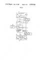
- FIG. 3shows the whole system of this invention.
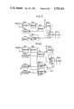
- FIG. 4shows the detail of a jag suppressor of this invention.
- FIG. 5shows a part of another jag suppressor of this invention.
- FIG. 6shows a part of yet another jag suppressor of this invention.
- FIG. 7shows a jag suppression process of this invention.
- FIG. 8shows several types of electronic filters composed of weight coefficients.
- FIG. 3shows a color scanner for printing to which the method of this invention is applied.
- An input scanning drum 2is revolved by a motor 1, while an original picture mounted on the drum 2 is scanned by an input scanning head 5 which is moved by a motor 4 along a feeding gear 6.
- Image signals obtained by scanning the original pictureundergo analog/digital conversion according to a sampling clock p which is obtained by processing multiple pulse output from a rotary encoder 3 in an input clock pulse producer 7.
- digitized image signals of three color components R, G and Bundergo processes of magnification conversion, RGB/YMCK conversion, gradation correction, color correction, recording mode exchanging, sharpness emphasis and so forth in an image processor 8 under the control of a control unit 18, and then input to a jag suppressor 9.
- the image signalundergo a jag suppression process of this invention in the jag suppressor 9 and then input to a recording process unit 10 in which the image data are synchronized with a recording clock pulse output from a recording clock pulse producer 11, and used for generating corresponding halftone dot signals. Then the halftone dot signals are used for driving a recording beam of a recording head 13 being moved along a feeding gear 14 by a motor 12 to record a reproduction image onto a photosensitive film mounted on a recording drum 16 being revolved by a motor 15.
- the input clock pulse producer 7outputs a sampling clock pulse P and a single pulse Q
- the recording clock pulse producer 11outputs a recording clock pulse P 0 and a single pulse Q 0 .
- FIG. 4shows the detail of the jag suppressor 9, in which the image data are 8 bit data.
- Density signal of a pixel of a scanning lineis input to a latch 9 -3-1 synchronizing with the risetime of the clock pulse P, and then the signal is input to corresponding address AS of a line buffer 9 -1 synchronizing with the falltime of the clock pulse P.
- the line buffer 9 -1already output the density signal of the pixel of the previous scanning line stored in the address AS to a latch 9 -3-3 .
- the image data to the latch 9 -3-3are also input to the address AS of a line buffer 9 -2 .
- the line buffer 9 -2already output the density signal of the pixel of the second previous scanning line stored in the address AS to a latch 9 -3-6 .
- the image data of the corresponding three pixels situated on three consecutive scanning linesare held on the latches 9 -3-1 , 9 -3-3 and 9 -3-6 at the same time. And then they are successively shifted to respective subsequent latches synchronously (9 -3-1 ⁇ 9 -3-2 , 9 -3-3 ⁇ 9 -3-4 ⁇ 9 -3-5 ; 9 -3-6 ⁇ 9.sub. -3-7).
- the density value V m of a center pixel I mis output from the latch 9 -3-4 , and the density values V b and V c of the surrounding pixels I b and I c (adjoining to the center pixel I m in the sub-scanning direction) are output from the latches 9 -3-2 and 9 -3-7 , while the density values V a and V d of the surrounding pixels I a and I d (adjoining to the center pixel I m in the main scanning direction) are output from the latches 9 -3-5 and 9 -3-3 .
- the value Sis a mediate value for obtaining a middle level density value J (mentioned later).
- the second term of the right membermeans that the sum of the density value of each surrounding pixel is multiplied by a weight coefficient of -1/4 as shown in FIG. 8(a).
- mediate value Sis inverted in an inverter 9 -6 to be an inverted value -S, and output to a multiplier 9 -7 .
- a specified value Uis registered in a register 9 -13 beforehand and is input to the multiplier 9 -7 .
- the multiplier 9 -7the inverted value -S is multiplied by the value U and the resultant value is output to an adder 9 -10 .
- the adder 9 -10adds the resultant value to the value V m being input from the latch 9 -3-4 to produce the value J:
- the value Jis a middle level density value to be input to a selector 9 -11 .
- Said inverted value -Sis also input to a comparator 9 -9 , to which a fixed value R registered in a register 9 -8 is input beforehand.
- the comparator 9 -9compares the value -S to the value R.
- the comparator 9 -9outputs a selection signal T of "H” (high level) to the selector 9 -11 to make it output the middle level density value J.
- the comparator 9 -9outputs a selection signal T of "L" (low level) to the selector 9 -11 to make it output the value V m of the center pixel I m .
- the output value of the selector 9 -11is input via a latch 9 -12 to the recording process unit 10.
- FIG. 7(a)shows a jagged border line on a conventional black-and-white image (the thick portion is expressed by "black-level (1)", while the thin portion is expressed by "white-level (0)").
- the mediate values S (S.sub. ⁇ , S.sub. ⁇ , S 65 and S.sub. ⁇ ) for pixels ⁇ , ⁇ , ⁇ and ⁇ of FIG. 7(a)are:
- FIG. 5shows another embodiment of this invention, from which the data order regulating means and the averaging circuit 9 -4 are eliminated for explanation because they are as same as the embodiment shown in FIG. 4.
- the mediate value Sis directly input to the comparator 9 -9 to be compared with the value R.
- the selector 9 -11outputs the middle level density value J.
- the selector 9 -11outputs the density value V m of the center pixel I m .
- the black-and-white image of FIG. 7(a)is processed by the circuit of FIG. 5 as in the following way.
- FIG. 6shows yet another embodiment of this invention, of which circuit structure is a combination of the circuits of FIGS. 4 and 5. That is, a comparator 9 -9-1 compares the inverted value -S obtained from the inverter 9 -6 with a fixed value R 1 stored in a register 9 -8-1 and outputs the selection signal T 1 of "H” when -S>R 1 , or outputs the signal T 1 of "L” when -S ⁇ R 1 . In the meantime, a comparator 9 -9-2 compares the value S obtained from the subtractor 9 -5 with a fixed value R 2 stored in a register 9 -8-2 and outputs the selection signal T 2 of "H” when S>R 2 , or the signal T 2 of "L” when S ⁇ R 2 .
- the selector 9 -11outputs the density value V m of the center pixel I m according to the selection signal of "L” when -R 1 ⁇ S ⁇ R 2 .
- the selector 9 -11outputs the middle level density value J according to the selection signal of "H” when R 1 ⁇ -S or S>R 2 .
- the abovementioned circuitsadopt a cross-shape electronic filter in which the center pixel is given the weight coefficient of 1 while each of four surrounding pixels are given that of -1/4 as shown in FIG. 8(a).
- the weight coefficient of the center pixel and the sum of the coefficients of the surrounding pixelsoffset each other, which fact can pass for any electronic weight coefficient filters of this invention.
- FIG. 8(b)shows another cross-shape imagenary filter in which the center pixel is given the weight coefficient of 1, while each of four surrounding pixels situated in the main scinning direction and four surrounding pixels situated in the sub-scanning direction symmetrically about the center pixel is given a weight coefficient of -1/8.
- FIG. 8(c)shows another cross-shape electronic filter in which the center pixel is given the weight coefficient of 1, while each of six surrounding pixels situated in the main scanning direction and six surrounding pixels situated in the sub-scanning direction symmetrically about the cinter pixel is given a weight coefficient of -1/12.
- FIG. 8(d)shows another cross-shape imaginary filter in which the center pixel is given the weight coefficient of 1, while each of two surrounding pixels situated in the main scanning direction and four surrounding pixels situated in the sub-scanning direction symmetrically about the center pixel is given a weight coefficient of -1/6.
- the sharpness emphasis processis carried out previously in the image processor 8 before the jag suppression process, the order can also be reversed.
- the method of this inventioncan be applied to a displaying monitor as well as to the abovementioned image reproducing system.
- the method of this inventionis capable of realizing a jag suppression process and smoothing process by means of a simple apparatus and algorithm, which have conventionally been very complicated. Therefore, when the method of this invention is applied to a displaying monitor, an economical displaying monitor of high resolution power can be realized. When it is applied to an image reproducing system, an economical image reproducing system capable of suppressing the appearance of jagged or intermittent lines can be obtained.
Landscapes
- Engineering & Computer Science (AREA)
- Multimedia (AREA)
- Signal Processing (AREA)
- Physics & Mathematics (AREA)
- General Physics & Mathematics (AREA)
- Theoretical Computer Science (AREA)
- Facsimile Image Signal Circuits (AREA)
- Image Processing (AREA)
Abstract
Description
S=V.sub.m -1/4(V.sub.a +V.sub.b +V.sub.c +V.sub.d) (1)
J=V.sub.m +(-S)·U (2)
S.sub.α =1-1/4·(1+1+0+1)=1/4·1
S.sub.β =1-1/4·(0+1+0+1)=1/2·1
S=0-1/4·(0+1+0+1)=-1/2·1
S=0-1/4·(0+1+0+0)=-1/4·1
Claims (17)
Applications Claiming Priority (2)
| Application Number | Priority Date | Filing Date | Title |
|---|---|---|---|
| JP58-212225 | 1983-11-10 | ||
| JP58212225AJPS60253368A (en) | 1983-11-10 | 1983-11-10 | Jag eliminating method for copied picture record display or the like |
Publications (1)
| Publication Number | Publication Date |
|---|---|
| US4703363Atrue US4703363A (en) | 1987-10-27 |
Family
ID=16619020
Family Applications (1)
| Application Number | Title | Priority Date | Filing Date |
|---|---|---|---|
| US06/669,784Expired - Fee RelatedUS4703363A (en) | 1983-11-10 | 1984-11-09 | Apparatus for smoothing jagged border lines |
Country Status (4)
| Country | Link |
|---|---|
| US (1) | US4703363A (en) |
| JP (1) | JPS60253368A (en) |
| DE (1) | DE3441063C2 (en) |
| GB (2) | GB8424491D0 (en) |
Cited By (37)
| Publication number | Priority date | Publication date | Assignee | Title |
|---|---|---|---|---|
| US4791679A (en)* | 1987-12-26 | 1988-12-13 | Eastman Kodak Company | Image character enhancement using a stroke strengthening kernal |
| US4876610A (en)* | 1986-12-25 | 1989-10-24 | Canon Kabushiki Kaisha | Image processing apparatus with binarization-error dispersal |
| US4924322A (en)* | 1988-03-18 | 1990-05-08 | Matsushita Electric Industrial Co., Ltd. | Bi-level image display signal processing apparatus |
| US5065255A (en)* | 1989-06-27 | 1991-11-12 | Fuji Photo Film Co., Ltd. | Method of and apparatus for smoothing an image having a periodic pattern |
| US5124811A (en)* | 1988-08-30 | 1992-06-23 | Canon Kabushiki Kaisha | Image encoding apparatus |
| US5128747A (en)* | 1988-02-29 | 1992-07-07 | General Electric Company | Television signal processing system for reducing diagonal image artifacts |
| US5134503A (en)* | 1989-07-21 | 1992-07-28 | Fuji Photo Film Co., Ltd. | Image processing apparatus |
| US5164997A (en)* | 1990-01-30 | 1992-11-17 | Ezel, Inc. | Method and apparatus for aligning images using pixels of closed contours |
| US5235434A (en)* | 1991-06-27 | 1993-08-10 | Polaroid Corporation | Method and apparatus for selectively adjusting the brightness of large regions of an image |
| US5276532A (en)* | 1991-11-26 | 1994-01-04 | Xerox Corporation | Split-level frame buffer |
| US5384866A (en)* | 1992-04-02 | 1995-01-24 | Ezel, Inc. | Thinning method of an image |
| US5579414A (en)* | 1992-10-19 | 1996-11-26 | Fast; Bruce B. | OCR image preprocessing method for image enhancement of scanned documents by reversing invert text |
| US5579450A (en)* | 1992-11-25 | 1996-11-26 | Ricoh Company, Ltd. | Image processing apparatus involving comparison of densities of three contiguous pixels |
| US5621823A (en)* | 1988-12-30 | 1997-04-15 | Yozan, Inc. | Image processing method for thinning lines using index values |
| US5644406A (en)* | 1995-05-11 | 1997-07-01 | Xerox Corporation | Method for selecting an optimum encoding process for a block of pixels from a plurality of predefined encoding processes |
| US5682249A (en)* | 1995-05-11 | 1997-10-28 | Xerox Corporation | Method of encoding an image at full resolution for storing in a reduced image buffer |
| US5684895A (en)* | 1995-05-11 | 1997-11-04 | Xerox Corporation | Method for decoding a compressed image |
| US5778105A (en)* | 1994-01-14 | 1998-07-07 | R.R. Donnelley & Sons Company | Method of and apparatus for removing artifacts from a reproduction |
| US5867142A (en)* | 1991-11-25 | 1999-02-02 | Xerox Corporation | System and method for processing an image having edges |
| US5870505A (en)* | 1996-03-14 | 1999-02-09 | Polaroid Corporation | Method and apparatus for pixel level luminance adjustment |
| US5966475A (en)* | 1997-02-20 | 1999-10-12 | Hewlett-Packard Company | System for enlarging and smoothing textual characters |
| EP0992942A1 (en)* | 1998-10-05 | 2000-04-12 | Agfa-Gevaert N.V. | Method for smoothing staircase effect in enlarged low resolution images |
| US6229920B1 (en)* | 1996-04-25 | 2001-05-08 | Delphi Systemsimulation Gmbh | Method of classifying and recognizing patterns by additive contour extraction and averaging |
| US20010048771A1 (en)* | 2000-05-25 | 2001-12-06 | Nec Corporation | Image processing method and system for interpolation of resolution |
| US6529637B1 (en) | 1989-05-22 | 2003-03-04 | Pixel Instruments Corporation | Spatial scan replication circuit |
| US20030107778A1 (en)* | 2001-12-10 | 2003-06-12 | Chen-Hsiang Shih | Method of compensating zipper image by K-value and method calculating K-value |
| US20040151400A1 (en)* | 2002-12-27 | 2004-08-05 | Yoshiharu Sasaki | Method and apparatus for recording jag-free image |
| US20040247165A1 (en)* | 2003-03-07 | 2004-12-09 | Kabushiki Kaisha Toshiba | Image processing apparatus and image processing method |
| US20050207676A1 (en)* | 2004-03-16 | 2005-09-22 | Wen-Kuo Lin | Method for decimating image data filtered by a bayer pattern color filter array |
| US20050276506A1 (en)* | 2004-06-09 | 2005-12-15 | Kwon Young-Jin | Apparatus and method to remove jagging artifact |
| US20060119904A1 (en)* | 2002-01-14 | 2006-06-08 | Transpacific Ip, Ltd. | Method of effacing zipper image |
| US7382929B2 (en) | 1989-05-22 | 2008-06-03 | Pixel Instruments Corporation | Spatial scan replication circuit |
| US20090179934A1 (en)* | 2006-09-19 | 2009-07-16 | Yasunobu Takagi | Image forming apparatus, image forming method, recording medium, and program |
| US20090195585A1 (en)* | 2008-02-05 | 2009-08-06 | Ricoh Company, Ltd. | Image forming method, computer-readable recording medium, image processing device, image forming apparatus, and image forming system |
| US20100158390A1 (en)* | 2008-12-23 | 2010-06-24 | Manoj Mathew | Parallel processing for generating a thinned image |
| CN105319894A (en)* | 2014-07-30 | 2016-02-10 | 京瓷办公信息系统株式会社 | Image forming apparatus and image forming method |
| WO2021102772A1 (en)* | 2019-11-28 | 2021-06-03 | Qualcomm Incorporated | Methods and apparatus to smooth edge portions of an irregularly-shaped display |
Families Citing this family (12)
| Publication number | Priority date | Publication date | Assignee | Title |
|---|---|---|---|---|
| DE3520405A1 (en)* | 1984-06-09 | 1985-12-12 | Fuji Photo Film Co., Ltd., Minami-Ashigara, Kanagawa | METHOD FOR PROCESSING IMAGE SIGNALS |
| JPS61203785A (en)* | 1985-03-07 | 1986-09-09 | Dainippon Screen Mfg Co Ltd | Method and device for smoothing binary picture data |
| DE3525049A1 (en)* | 1985-07-13 | 1987-01-15 | Thomson Brandt Gmbh | METHOD AND / OR DEVICE FOR IMPROVING THE STILL IMAGE |
| US5109430A (en)* | 1986-07-22 | 1992-04-28 | Schlumberger Technologies, Inc. | Mask alignment and measurement of critical dimensions in integrated circuits |
| JPS63170936A (en)* | 1986-07-22 | 1988-07-14 | フエアチヤイルド セミコンダクタ コ−ポレ−シヨン | Mask alignment and critical dimension measurement in integrated circuit |
| US5119444A (en)* | 1986-07-22 | 1992-06-02 | Schlumberger Technologies, Inc. | System for expedited computation of laplacian and gaussian filters and correlation of their outputs for image processing |
| JPS6410782A (en)* | 1987-07-02 | 1989-01-13 | Mitsubishi Electric Corp | Image printer |
| DE69212192T2 (en)* | 1991-03-27 | 1996-12-05 | Canon Kk | Image processing device |
| US5799111A (en)* | 1991-06-14 | 1998-08-25 | D.V.P. Technologies, Ltd. | Apparatus and methods for smoothing images |
| US5442462A (en)* | 1992-06-10 | 1995-08-15 | D.V.P. Technologies Ltd. | Apparatus and method for smoothing images |
| WO1992022876A1 (en)* | 1991-06-14 | 1992-12-23 | David Guissin | Apparatus and method for smoothing images |
| JPH08317252A (en)* | 1995-05-16 | 1996-11-29 | Ikegami Tsushinki Co Ltd | Contour correction method and apparatus |
Citations (11)
| Publication number | Priority date | Publication date | Assignee | Title |
|---|---|---|---|---|
| US3187304A (en)* | 1957-08-29 | 1965-06-01 | Ibm | System for analysing the spatial distribution of a function |
| JPS5248929A (en)* | 1975-10-17 | 1977-04-19 | Hitachi Ltd | Enlarged character correction system |
| JPS54136135A (en)* | 1978-04-13 | 1979-10-23 | Iryo Gijutsu Kenkyu Kaihatsu Zaidan | Picture information processor |
| JPS55114073A (en)* | 1979-02-22 | 1980-09-03 | Mitsubishi Electric Corp | Picture display system |
| JPS5922764A (en)* | 1982-07-29 | 1984-02-06 | Fuji Xerox Co Ltd | Method for correcting enlarged character |
| US4437122A (en)* | 1981-09-12 | 1984-03-13 | Xerox Corporation | Low resolution raster images |
| US4460909A (en)* | 1981-12-18 | 1984-07-17 | International Business Machines Corporation | Method and apparatus for enhancing the resolution of an electrophotographic printer |
| US4486785A (en)* | 1982-09-30 | 1984-12-04 | International Business Machines Corporation | Enhancement of video images by selective introduction of gray-scale pels |
| US4506382A (en)* | 1981-04-25 | 1985-03-19 | Nippon Kogaku K.K. | Apparatus for detecting two-dimensional pattern and method for transforming the pattern into binary image |
| US4539704A (en)* | 1983-09-15 | 1985-09-03 | Pitney Bowes Inc. | Image thinning process |
| US4551768A (en)* | 1982-10-27 | 1985-11-05 | Matsushita Electric Industrial Co., Ltd. | Method and apparatus for processing image signal |
- 1983
- 1983-11-10JPJP58212225Apatent/JPS60253368A/enactiveGranted
- 1984
- 1984-09-28GBGB848424491Apatent/GB8424491D0/enactivePending
- 1984-11-08GBGB08428212Apatent/GB2151104B/ennot_activeExpired
- 1984-11-09USUS06/669,784patent/US4703363A/ennot_activeExpired - Fee Related
- 1984-11-09DEDE3441063Apatent/DE3441063C2/ennot_activeExpired
Patent Citations (12)
| Publication number | Priority date | Publication date | Assignee | Title |
|---|---|---|---|---|
| US3187304A (en)* | 1957-08-29 | 1965-06-01 | Ibm | System for analysing the spatial distribution of a function |
| JPS5248929A (en)* | 1975-10-17 | 1977-04-19 | Hitachi Ltd | Enlarged character correction system |
| JPS54136135A (en)* | 1978-04-13 | 1979-10-23 | Iryo Gijutsu Kenkyu Kaihatsu Zaidan | Picture information processor |
| JPS55114073A (en)* | 1979-02-22 | 1980-09-03 | Mitsubishi Electric Corp | Picture display system |
| US4506382A (en)* | 1981-04-25 | 1985-03-19 | Nippon Kogaku K.K. | Apparatus for detecting two-dimensional pattern and method for transforming the pattern into binary image |
| US4437122A (en)* | 1981-09-12 | 1984-03-13 | Xerox Corporation | Low resolution raster images |
| US4437122B1 (en)* | 1981-09-12 | 1993-03-30 | Xerox Corp | |
| US4460909A (en)* | 1981-12-18 | 1984-07-17 | International Business Machines Corporation | Method and apparatus for enhancing the resolution of an electrophotographic printer |
| JPS5922764A (en)* | 1982-07-29 | 1984-02-06 | Fuji Xerox Co Ltd | Method for correcting enlarged character |
| US4486785A (en)* | 1982-09-30 | 1984-12-04 | International Business Machines Corporation | Enhancement of video images by selective introduction of gray-scale pels |
| US4551768A (en)* | 1982-10-27 | 1985-11-05 | Matsushita Electric Industrial Co., Ltd. | Method and apparatus for processing image signal |
| US4539704A (en)* | 1983-09-15 | 1985-09-03 | Pitney Bowes Inc. | Image thinning process |
Cited By (53)
| Publication number | Priority date | Publication date | Assignee | Title |
|---|---|---|---|---|
| US4876610A (en)* | 1986-12-25 | 1989-10-24 | Canon Kabushiki Kaisha | Image processing apparatus with binarization-error dispersal |
| US4791679A (en)* | 1987-12-26 | 1988-12-13 | Eastman Kodak Company | Image character enhancement using a stroke strengthening kernal |
| US5128747A (en)* | 1988-02-29 | 1992-07-07 | General Electric Company | Television signal processing system for reducing diagonal image artifacts |
| US4924322A (en)* | 1988-03-18 | 1990-05-08 | Matsushita Electric Industrial Co., Ltd. | Bi-level image display signal processing apparatus |
| US5124811A (en)* | 1988-08-30 | 1992-06-23 | Canon Kabushiki Kaisha | Image encoding apparatus |
| US5621823A (en)* | 1988-12-30 | 1997-04-15 | Yozan, Inc. | Image processing method for thinning lines using index values |
| US7822284B2 (en) | 1989-05-22 | 2010-10-26 | Carl Cooper | Spatial scan replication circuit |
| US6529637B1 (en) | 1989-05-22 | 2003-03-04 | Pixel Instruments Corporation | Spatial scan replication circuit |
| US7986851B2 (en) | 1989-05-22 | 2011-07-26 | Cooper J Carl | Spatial scan replication circuit |
| US7382929B2 (en) | 1989-05-22 | 2008-06-03 | Pixel Instruments Corporation | Spatial scan replication circuit |
| US5065255A (en)* | 1989-06-27 | 1991-11-12 | Fuji Photo Film Co., Ltd. | Method of and apparatus for smoothing an image having a periodic pattern |
| US5134503A (en)* | 1989-07-21 | 1992-07-28 | Fuji Photo Film Co., Ltd. | Image processing apparatus |
| US5164997A (en)* | 1990-01-30 | 1992-11-17 | Ezel, Inc. | Method and apparatus for aligning images using pixels of closed contours |
| US5235434A (en)* | 1991-06-27 | 1993-08-10 | Polaroid Corporation | Method and apparatus for selectively adjusting the brightness of large regions of an image |
| US5867142A (en)* | 1991-11-25 | 1999-02-02 | Xerox Corporation | System and method for processing an image having edges |
| US5276532A (en)* | 1991-11-26 | 1994-01-04 | Xerox Corporation | Split-level frame buffer |
| US5384866A (en)* | 1992-04-02 | 1995-01-24 | Ezel, Inc. | Thinning method of an image |
| US5594815A (en)* | 1992-10-19 | 1997-01-14 | Fast; Bruce B. | OCR image preprocessing method for image enhancement of scanned documents |
| US5590224A (en)* | 1992-10-19 | 1996-12-31 | Fast; Bruce B. | OCR image preprocessing method for image enhancement of scanned documents by correction of registration |
| US5579414A (en)* | 1992-10-19 | 1996-11-26 | Fast; Bruce B. | OCR image preprocessing method for image enhancement of scanned documents by reversing invert text |
| US5625719A (en)* | 1992-10-19 | 1997-04-29 | Fast; Bruce B. | OCR image preprocessing method for image enhancement of scanned documents |
| US5594817A (en)* | 1992-10-19 | 1997-01-14 | Fast; Bruce B. | OCR image pre-processor for detecting and reducing skew of the image of textual matter of a scanned document |
| US5729635A (en)* | 1992-10-19 | 1998-03-17 | Tmssequoia | OCR image free-processing method for image enhancement of scanned documents |
| US5594814A (en)* | 1992-10-19 | 1997-01-14 | Fast; Bruce B. | OCR image preprocessing method for image enhancement of scanned documents |
| US5579450A (en)* | 1992-11-25 | 1996-11-26 | Ricoh Company, Ltd. | Image processing apparatus involving comparison of densities of three contiguous pixels |
| US5778105A (en)* | 1994-01-14 | 1998-07-07 | R.R. Donnelley & Sons Company | Method of and apparatus for removing artifacts from a reproduction |
| US5684895A (en)* | 1995-05-11 | 1997-11-04 | Xerox Corporation | Method for decoding a compressed image |
| US5682249A (en)* | 1995-05-11 | 1997-10-28 | Xerox Corporation | Method of encoding an image at full resolution for storing in a reduced image buffer |
| US5644406A (en)* | 1995-05-11 | 1997-07-01 | Xerox Corporation | Method for selecting an optimum encoding process for a block of pixels from a plurality of predefined encoding processes |
| US5870505A (en)* | 1996-03-14 | 1999-02-09 | Polaroid Corporation | Method and apparatus for pixel level luminance adjustment |
| US6229920B1 (en)* | 1996-04-25 | 2001-05-08 | Delphi Systemsimulation Gmbh | Method of classifying and recognizing patterns by additive contour extraction and averaging |
| US5966475A (en)* | 1997-02-20 | 1999-10-12 | Hewlett-Packard Company | System for enlarging and smoothing textual characters |
| EP0992942A1 (en)* | 1998-10-05 | 2000-04-12 | Agfa-Gevaert N.V. | Method for smoothing staircase effect in enlarged low resolution images |
| US20010048771A1 (en)* | 2000-05-25 | 2001-12-06 | Nec Corporation | Image processing method and system for interpolation of resolution |
| US20070035787A1 (en)* | 2001-10-23 | 2007-02-15 | Transpacific Ip, Ltd. | Method of compensating a zipper image by a K-value and a method of calculating a K-value |
| US7847987B2 (en) | 2001-10-23 | 2010-12-07 | Chen-Hsiang Shih | Method of compensating a zipper image by a K-value and a method of calculating a K-value |
| US20030107778A1 (en)* | 2001-12-10 | 2003-06-12 | Chen-Hsiang Shih | Method of compensating zipper image by K-value and method calculating K-value |
| US7515317B2 (en)* | 2001-12-10 | 2009-04-07 | Chen-Hsiang Shih | Compensating a zipper image by a K-value |
| US7710612B2 (en) | 2002-01-14 | 2010-05-04 | Chen-Hsiang Shih | Method of effacing zipper image |
| US20060119904A1 (en)* | 2002-01-14 | 2006-06-08 | Transpacific Ip, Ltd. | Method of effacing zipper image |
| US20040151400A1 (en)* | 2002-12-27 | 2004-08-05 | Yoshiharu Sasaki | Method and apparatus for recording jag-free image |
| US20040247165A1 (en)* | 2003-03-07 | 2004-12-09 | Kabushiki Kaisha Toshiba | Image processing apparatus and image processing method |
| US20050207676A1 (en)* | 2004-03-16 | 2005-09-22 | Wen-Kuo Lin | Method for decimating image data filtered by a bayer pattern color filter array |
| NL1029212C2 (en)* | 2004-06-09 | 2006-11-01 | Samsung Electronics Co Ltd | Image`s jagging artifacts e.g. staircasing, removing apparatus for use in image quality processing system, has low pass filter for filtering window based on calculated eigen vector and filtering weight |
| CN100353755C (en)* | 2004-06-09 | 2007-12-05 | 三星电子株式会社 | Apparatus and method to remove jagging artifact |
| US20050276506A1 (en)* | 2004-06-09 | 2005-12-15 | Kwon Young-Jin | Apparatus and method to remove jagging artifact |
| US20090179934A1 (en)* | 2006-09-19 | 2009-07-16 | Yasunobu Takagi | Image forming apparatus, image forming method, recording medium, and program |
| US20090195585A1 (en)* | 2008-02-05 | 2009-08-06 | Ricoh Company, Ltd. | Image forming method, computer-readable recording medium, image processing device, image forming apparatus, and image forming system |
| US20100158390A1 (en)* | 2008-12-23 | 2010-06-24 | Manoj Mathew | Parallel processing for generating a thinned image |
| US8238682B2 (en)* | 2008-12-23 | 2012-08-07 | Canon Kabushiki Kaisha | Parallel processing for generating a thinned image |
| CN105319894A (en)* | 2014-07-30 | 2016-02-10 | 京瓷办公信息系统株式会社 | Image forming apparatus and image forming method |
| CN105319894B (en)* | 2014-07-30 | 2018-05-22 | 京瓷办公信息系统株式会社 | Image forming apparatus and image forming method |
| WO2021102772A1 (en)* | 2019-11-28 | 2021-06-03 | Qualcomm Incorporated | Methods and apparatus to smooth edge portions of an irregularly-shaped display |
Also Published As
| Publication number | Publication date |
|---|---|
| DE3441063C2 (en) | 1986-08-21 |
| JPS60253368A (en) | 1985-12-14 |
| GB2151104B (en) | 1987-06-03 |
| GB2151104A (en) | 1985-07-10 |
| DE3441063A1 (en) | 1985-06-05 |
| GB8424491D0 (en) | 1984-11-07 |
| JPS6349426B2 (en) | 1988-10-04 |
| GB8428212D0 (en) | 1984-12-19 |
Similar Documents
| Publication | Publication Date | Title |
|---|---|---|
| US4703363A (en) | Apparatus for smoothing jagged border lines | |
| US4844288A (en) | Reproduction picture sharpness emphasizing method and apparatus | |
| EP0198161B1 (en) | Method for emphasizing sharpness in a picture signal reproducing machine | |
| US5210602A (en) | Coupled-color error diffusion | |
| US5375002A (en) | Color error diffusion | |
| EP0187534B1 (en) | Color signal processing apparatus with a signal interpolation function for use in a color copier | |
| US4551768A (en) | Method and apparatus for processing image signal | |
| US5519791A (en) | Block parallel error diffusion method and apparatus | |
| EP0272147A2 (en) | Bi-level image display signal processing apparatus | |
| US4692811A (en) | Apparatus for processing image signal | |
| GB1602557A (en) | Electronic halftone screening | |
| JPH03149667A (en) | Efficient data memory system for gray scale printer | |
| US4533942A (en) | Method and apparatus for reproducing an image which has a coarser resolution than utilized in scanning of the image | |
| JP3067304B2 (en) | Pattern generation method for color image processing device | |
| US5453853A (en) | Color video still image processing system | |
| US5506698A (en) | Image reproducing apparatus and process wherein minimized average error technique is used for each of fractions of original pel intensity value | |
| JPH0224073B2 (en) | ||
| WO1989006080A1 (en) | Image processor with error diffusion modulated threshold matrix | |
| JP3175936B2 (en) | Image processing device | |
| JPH042034B2 (en) | ||
| JP2893700B2 (en) | Image processing device | |
| JP2592066B2 (en) | Image processing device | |
| JP2958965B2 (en) | Image processing device | |
| KR840001217B1 (en) | Masking calculation method in digital color control | |
| JPH0541793A (en) | Digital image processor |
Legal Events
| Date | Code | Title | Description |
|---|---|---|---|
| AS | Assignment | Owner name:DAINIPPON SCREEN MFG. CO., LTD., KYOTO, JAPAN Free format text:ASSIGNMENT OF ASSIGNORS INTEREST.;ASSIGNOR:KITAMURA, HIDEAKI;REEL/FRAME:004334/0920 Effective date:19841105 Owner name:DAINIPPON SCREEN MFG. CO., LTD.,JAPAN Free format text:ASSIGNMENT OF ASSIGNORS INTEREST;ASSIGNOR:KITAMURA, HIDEAKI;REEL/FRAME:004334/0920 Effective date:19841105 | |
| FEPP | Fee payment procedure | Free format text:PAYOR NUMBER ASSIGNED (ORIGINAL EVENT CODE: ASPN); ENTITY STATUS OF PATENT OWNER: LARGE ENTITY | |
| FPAY | Fee payment | Year of fee payment:4 | |
| FEPP | Fee payment procedure | Free format text:PAYER NUMBER DE-ASSIGNED (ORIGINAL EVENT CODE: RMPN); ENTITY STATUS OF PATENT OWNER: LARGE ENTITY Free format text:PAYOR NUMBER ASSIGNED (ORIGINAL EVENT CODE: ASPN); ENTITY STATUS OF PATENT OWNER: LARGE ENTITY | |
| REMI | Maintenance fee reminder mailed | ||
| LAPS | Lapse for failure to pay maintenance fees | ||
| FP | Lapsed due to failure to pay maintenance fee | Effective date:19951101 | |
| STCH | Information on status: patent discontinuation | Free format text:PATENT EXPIRED DUE TO NONPAYMENT OF MAINTENANCE FEES UNDER 37 CFR 1.362 |