US4702108A - Method and apparatus for measuring the isometric muscle strength of multiple muscle groups in the human body - Google Patents
Method and apparatus for measuring the isometric muscle strength of multiple muscle groups in the human bodyDownload PDFInfo
- Publication number
- US4702108A US4702108AUS06/825,851US82585186AUS4702108AUS 4702108 AUS4702108 AUS 4702108AUS 82585186 AUS82585186 AUS 82585186AUS 4702108 AUS4702108 AUS 4702108A
- Authority
- US
- United States
- Prior art keywords
- testing
- muscle groups
- track
- muscle
- groups selected
- Prior art date
- Legal status (The legal status is an assumption and is not a legal conclusion. Google has not performed a legal analysis and makes no representation as to the accuracy of the status listed.)
- Expired - Fee Related
Links
- 210000003205muscleAnatomy0.000titleclaimsabstractdescription126
- 238000000034methodMethods0.000titleabstractdescription14
- 238000012360testing methodMethods0.000claimsabstractdescription93
- 230000003100immobilizing effectEffects0.000claimsabstractdescription6
- 230000033001locomotionEffects0.000claimsdescription23
- 230000006641stabilisationEffects0.000claimsdescription9
- 238000011105stabilizationMethods0.000claimsdescription9
- 238000004873anchoringMethods0.000claims1
- 210000002414legAnatomy0.000abstractdescription20
- 244000309466calfSpecies0.000abstractdescription18
- 210000000038chestAnatomy0.000abstractdescription18
- 210000000689upper legAnatomy0.000abstractdescription17
- 210000004197pelvisAnatomy0.000abstractdescription7
- 210000004027cellAnatomy0.000description65
- 210000002683footAnatomy0.000description38
- 238000005259measurementMethods0.000description26
- 210000003127kneeAnatomy0.000description19
- 210000001624hipAnatomy0.000description17
- 230000007246mechanismEffects0.000description16
- 210000003423ankleAnatomy0.000description12
- 230000000712assemblyEffects0.000description7
- 238000000429assemblyMethods0.000description7
- 239000002184metalSubstances0.000description7
- NJPPVKZQTLUDBO-UHFFFAOYSA-NnovaluronChemical compoundC1=C(Cl)C(OC(F)(F)C(OC(F)(F)F)F)=CC=C1NC(=O)NC(=O)C1=C(F)C=CC=C1FNJPPVKZQTLUDBO-UHFFFAOYSA-N0.000description7
- 230000009471actionEffects0.000description6
- 230000006835compressionEffects0.000description6
- 238000007906compressionMethods0.000description6
- 230000008602contractionEffects0.000description6
- 230000000452restraining effectEffects0.000description6
- 230000000087stabilizing effectEffects0.000description6
- 210000002027skeletal muscleAnatomy0.000description5
- 230000004118muscle contractionEffects0.000description4
- 239000003381stabilizerSubstances0.000description4
- 238000005452bendingMethods0.000description3
- 238000010586diagramMethods0.000description3
- 230000006870functionEffects0.000description3
- 230000036316preloadEffects0.000description3
- 238000012545processingMethods0.000description3
- 230000004044responseEffects0.000description3
- 210000000115thoracic cavityAnatomy0.000description3
- 238000004458analytical methodMethods0.000description2
- 238000000418atomic force spectrumMethods0.000description2
- 210000000988bone and boneAnatomy0.000description2
- 238000006243chemical reactionMethods0.000description2
- 238000004590computer programMethods0.000description2
- 230000003750conditioning effectEffects0.000description2
- 201000010099diseaseDiseases0.000description2
- 208000037265diseases, disorders, signs and symptomsDiseases0.000description2
- 230000009977dual effectEffects0.000description2
- 230000000694effectsEffects0.000description2
- 230000007274generation of a signal involved in cell-cell signalingEffects0.000description2
- 239000000463materialSubstances0.000description2
- 210000004237neck muscleAnatomy0.000description2
- 230000002123temporal effectEffects0.000description2
- 238000012549trainingMethods0.000description2
- 238000012546transferMethods0.000description2
- HGCIXCUEYOPUTN-UHFFFAOYSA-NC1CC=CCC1Chemical compoundC1CC=CCC1HGCIXCUEYOPUTN-UHFFFAOYSA-N0.000description1
- 208000021642Muscular diseaseDiseases0.000description1
- 230000009087cell motilityEffects0.000description1
- 230000007248cellular mechanismEffects0.000description1
- 238000004891communicationMethods0.000description1
- 238000007405data analysisMethods0.000description1
- 238000013480data collectionMethods0.000description1
- 238000013500data storageMethods0.000description1
- 230000003247decreasing effectEffects0.000description1
- 230000000881depressing effectEffects0.000description1
- 238000003745diagnosisMethods0.000description1
- 238000002955isolationMethods0.000description1
- 210000001087myotubuleAnatomy0.000description1
- 230000000737periodic effectEffects0.000description1
- 230000008569processEffects0.000description1
- 238000011160researchMethods0.000description1
- 230000000717retained effectEffects0.000description1
- 238000012552reviewMethods0.000description1
- 238000004904shorteningMethods0.000description1
- 210000003813thumbAnatomy0.000description1
- 230000007704transitionEffects0.000description1
Images


Classifications
- A—HUMAN NECESSITIES
- A61—MEDICAL OR VETERINARY SCIENCE; HYGIENE
- A61B—DIAGNOSIS; SURGERY; IDENTIFICATION
- A61B5/00—Measuring for diagnostic purposes; Identification of persons
- A61B5/22—Ergometry; Measuring muscular strength or the force of a muscular blow
- A61B5/224—Measuring muscular strength
- A—HUMAN NECESSITIES
- A61—MEDICAL OR VETERINARY SCIENCE; HYGIENE
- A61B—DIAGNOSIS; SURGERY; IDENTIFICATION
- A61B5/00—Measuring for diagnostic purposes; Identification of persons
- A61B5/45—For evaluating or diagnosing the musculoskeletal system or teeth
- A61B5/4528—Joints
- Y—GENERAL TAGGING OF NEW TECHNOLOGICAL DEVELOPMENTS; GENERAL TAGGING OF CROSS-SECTIONAL TECHNOLOGIES SPANNING OVER SEVERAL SECTIONS OF THE IPC; TECHNICAL SUBJECTS COVERED BY FORMER USPC CROSS-REFERENCE ART COLLECTIONS [XRACs] AND DIGESTS
- Y10—TECHNICAL SUBJECTS COVERED BY FORMER USPC
- Y10S—TECHNICAL SUBJECTS COVERED BY FORMER USPC CROSS-REFERENCE ART COLLECTIONS [XRACs] AND DIGESTS
- Y10S482/00—Exercise devices
- Y10S482/901—Exercise devices having computer circuitry
Definitions
- the present inventionrelates to a method and apparatus for measuring and recording the isometric muscle strength of many if not all of the major skeletal muscle groups in the human body. More particularly, the present invention relates to a chair apparatus and method of using the same, providing for testing of multiple major skeletal muscle groups at a single test station.
- Muscle strengthcan be defined as the ability of a muscle or group of muscles to produce tension or exert force through the human skeletal system.
- the musclemay contract in three different ways: (1) concentrically (force is generated while the muscle is shortening in length); (2) eccentrically (force occurs while the muscle is being elongated; and (3) isometrically (force is generated by a muscle whose length is not changing).
- the generally accepted measurement criterion for the maximum tension which can be exerted by a muscleis the maximum amount of force a muscle can exert on a body part. This is referred to as the maximum strength of the muscle and might be expressed, for example, in kilograms per square centimeter of transverse section.
- Strength measurementsshould be taken at a proportional distance from the axis of rotation of the body part when comparing measurements from different subjects. This is particularly important when the force exerted by the body part is the parameter to be measured. With respect to this methodology, moment measurements should also be taken at a proportional distance from the axis of rotation.
- Muscle strength testing devicestypically utilize a rotating input shaft. If concentric, eccentric and/or isometric strength is to be measured, an accurate positioning of the axis of rotation of the rotating input shaft of the apparatus taking the measurement with the actual center of rotation of the body segment being assessed is required. Reasonably adequate placement has been achieved by a significant number of currently available muscle strength testing devices for testing the knee.
- a widely used device for measuring strength and endurance of human musclesis the Cybex II apparatus, which is described in various materials and in U.S. Pat. No. 3,465,592. However, as discussed above, this device requires that the axis of rotation of the rotating input shaft of the apparatus taking the measurement be aligned with the anatomical center of rotation of the body segment being assessed.
- a recently issued patent(U.S. Pat. No. 4,462,252) describes a method and apparatus for measuring the strength of the flexors and extensors of the trunk; however, this device measures the muscle strength and endurance for only this one part of the body.
- This device and other devicesare designed to measure concentric and often eccentric strength with the incidental ability to assess isometric strength.
- the complex and bulky speed control/load cell mechanisms required to test concentric and eccentric strengthare difficult, if not impossible, to move from one skeletal muscle group site to another and assure proper alignment therewith so as to enable testing of multiple muscle groups at a single device or testing station.
- the muscle groups to be testedmust be isolated from muscle groups which may contribute a moment of force to the apparatus measuring the muscle groups. Accordingly, the human subject must be positioned appropriately and the parts of the body containing muscles which are not part of the measurement must be stabilized or immobilized.
- Prior art deviceshave typically not been capable of providing adequate stabilization of body parts not being tested and/or of appropriately aligning force measuring components for most if not all of the major muscle groups of the body at a single device or station.
- individual devicesmay adequately stabilize the subject and align the device for a single or limited number of muscle groups, but these devices are not capable of appropriate stabilization and alignment for most if not all of the major muscle groups of the human body.
- the present inventionsolves these and many other problems associated with prior muscle strength and endurance testing devices.
- the present inventionrelates to an isometric muscle strength testing chair apparatus for measuring the isometric muscle strength of any of a plurality of muscle groups in a human subject's body.
- the chair apparatusincludes a support having a seat assembly and a foot rest assembly mounted thereon.
- the chair apparatusincludes stabilization means for selectively engaging and immobilizing various parts of the human subject's body, including the pelvis, thorax, thighs and legs as required to enable each of the muscle groups selected for testing to be tested while being isolated from the other muscle groups of the human subject's body.
- the chair apparatusfurther includes transducer means for measuring the force exerted by the muscle groups selected for testing, the transducer means remaining substantially stationary while the muscle groups selected for testing exert a force thereon so as to provide for isometric strength testing. Track means enables the transducer means to be adjustably positioned in association with the muscle groups selected for testing.
- the present inventionalso relates to a method for measuring isometric muscle strength of any of a plurality of muscle groups in a human subject's body.
- the methodincludes the step of seating the human subject in a chair apparatus having a seat assembly and foot rest assembly.
- Various parts of the human subject's bodyincluding the pelvis, thorax, thighs and legs are selectively immobilized as required for isolating the muscle groups being tested from the other muscle groups.
- Transducer meansis adjustably positioned in substantially stationary association with the muscle groups selected for testing. Force is isometrically applied to the transducer means by the muscles selected for testing. The transducer means generates an output signal in response to the isometrically applied force. This signal is monitored to provide an indication of the isometric muscle strength.
- a primary object of this inventionis to provide a method and apparatus for measuring the isometric muscle strength of most if not all of the major skeletal muscle groups in the human body.
- a computer controlled systemis utilized for measuring isometric muscle contractions by use of a suitable transducer, such as tension/compression load cells.
- An object of an embodiment of this inventionis to provide a method and apparatus for isometric muscle endurance testing as well as strength testing. Yet another object of an embodiment of this invention is to provide a method and apparatus for isometric exercise training.
- a further object of yet another embodiment of the present inventionis to store the muscle strength data collected and perform further processing thereon and/or transfer the processed and/or unprocessed data to a local client data base and/or a central computer.
- the spinecan be further separated into the following actions:
- compression/tension load cellssuch as 500 and 1,000 pound load cells, models SM-500 and SM-1000, respectively, an analog to digital signal conversion system, a personal computer such as an Apple IIE, and appropriate computer programs for measuring isometric muscle strength and endurance.
- the apparatusconsists of a framework which supports a seat which can be moved forward and backward, a foot rest which can be adjusted up and down, strap stabilization devices and tracks for the adjustable placement of load cells. Strap restraining devices are utilized to stabilize the pelvis, thighs, legs and thorax as needed for specific muscle-joint actions. This enables specific muscle-joint actions and thereby muscle groups to be tested rapidly and in isolation.
- Posterior TrackThe load cell which is used to measure trunk extension and neck extension strength and endurance is mounted on the posterior track.
- This trackallows load cell movement laterally, forwardly along the thigh and up and down to the foot and ankle.
- This track systemallows the measurement of ankle plantar and dorsiflextion, hip flexion and extension, hip abduction and adduction, hip rotation (internal and external), elbow flexion and extension, shoulder flexion and extension and shoulder rotation (internal and external) strength and endurance.
- itis an object to provide categorizing of amplitude and temporal factors, including measurement of EMG and parameters related to the timing of the EMG with respect to the force response. In addition to other advantages, this allows for the possible determination of muscle fiber type and fatigue characteristics.
- One embodiment of the present inventioncan be used with very weak people, since the slightest amounts of force can be measured, unlike that of conventional cable and chair systems, which require several pounds of force just to take up slack in the system.
- lever arm lengthscan be measured thereby enabling torques to be determined by the invention.
- FIG. 1is a view in perspective of an embodiment of the chair apparatus in accordance with the principles of the present invention
- FIG. 2is a view of the embodiment shown in FIG. 1, as seen generally from the top;
- FIG. 3is a view of the embodiment shown in FIG. 1, as seen generally from the side;
- FIG. 4is a view of the embodiment shown in FIG. 1, as seen generally from the front;
- FIG. 5is a view of the embodiment shown in FIG. 1, as seen generally from the back;
- FIG. 6is a view of the embodiment shown in FIG. 1, as seen generally from the bottom;
- FIG. 7is an enlarged perspective of an embodiment of a thorax restrain assembly in accordance with the principles of the present invention.
- FIG. 8is a perspective view of an embodiment of a T-block apparatus in accordance with the present invention.
- FIG. 9is a perspective view of an embodiment of a pivotal mounting assembly interconnected to an embodiment of a T-block assembly, as shown in FIG. 8;
- FIG. 10is a view as seen generally along the line 10--10 in FIG. 9;
- FIG. 11Ais a cross-sectional view of the embodiment shown in FIG. 10;
- FIG. 11Bis a view similar to FIG. 11A with the latch in the locked position
- FIG. 12is an enlarged perspective view illustrating an embodiment of a load cell mounting arrangement in accordance with the principles of the present invention.
- FIG. 13is an enlarged cross-sectional view of an embodiment of an attachment apparatus for attaching the load cells to various cuffs and pads;
- FIG. 14is an alternate embodiment of the attachment apparatus illustrated in FIG. 13;
- FIGS. 15 through 19are perspective views of embodiments of various cuff apparatus in accordance with the principles of the present invention.
- FIG. 20is an enlarged fragmentary perspective view of an embodiment of an extension apparatus in accordance with the principles of the present invention.
- FIG. 21is a perspective view of an embodiment of a latch mechanism
- FIG. 22is a perspective view of yet another embodiment of a latch apparatus in accordance with the present invention.
- FIG. 23is a view as seen generally along line 23 in FIG. 22;
- FIG. 24is an enlarged perspective view of an alternate embodiment of the foot plates and calf restraints in accordance with the principles of the present invention.
- FIG. 25is a perspective view of an embodiment of the mechanism for securedly attaching the foot plates to the foot rest assembly
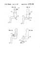
- FIGS. 26 through 33are diagrammatic drawings illustrating testing of various muscle groups
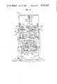
- FIG. 34is a block diagram of a computer controlled system in accordance with the principles of the present invention.
- FIG. 35is a graph of various input parameters in accordance with the principles of the present invention.
- FIG. 36is a sample printout obtained upon completion of muscle strength testing
- FIG. 37is a logic flow diagram of an embodiment of a logic sequence implemented in accordance with the principles of the present invention.
- FIGS. 38A-Care logic flow diagrams of an embodiment of a logic flow sequence for processing various input parameters.
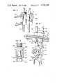
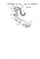
- FIGS. 39-43illustrate an alternate embodiment of the chair apparatus in accordance with the principles of the present invention.
- FIG. 1an embodiment of a chair apparatus, generally identified by the reference numeral 40, in accordance with the principles of the present invention.
- the embodiment of the chair apparatus 40 illustratedincludes a support frame structure 42 mounted on four adjustable foot pads 44.
- the chair apparatus 40further includes a seat assembly 46 for seating of the patient or subject to be tested.
- the seat assembly 46is horizontally adjustable in a forward and a backward direction with respect to the subject by operation of a crank 48 on a rear side of the chair apparatus 40, roughly in the center, just below a seat pad 50 of the seat assembly 46.
- the embodiment of the chair apparatus 40 shownfurther includes a foot rest assembly 60 positioned generally forwardly of and downwardly from the seat assembly 46.
- the foot rest assembly 60is vertically adjustable by use of a crank 62 on a right side of the chair apparatus 40 which causes a vertical screw rod assembly 61 interconnected to the foot rest assembly 60 to turn, thereby causing the foot rest assembly 60 to move vertically along slots 63 in the support frame.
- the foot rest assembly 60includes a platform 64 which is raised and lowered by the crank 62 and two foot plates 66 positioned in slots 65 of the platform which can be adjustably positioned forward, backward and/or pivoted to a more comfortable position. This is accomplished by loosening the footplates 66 by use of a lever 68 on a left side of the chair apparatus 40. The footplates 66 are locked in place by pushing the lever 68 backwardly and downwardly.
- the chair apparatus 40includes six track systems which enable placement of load cells at any number of specific locations.
- the six track systems presentinclude a posterior track 80a at the back of the chair apparatus 40, left and right lateral tracks 80b, 80c generally along the left and right sides of the chair apparatus 40, respectively, an anterior track 80d extending generally across in front of the chair apparatus 40, a forward upper track 80e positioned slightly in front of and below the anterior track 80d and a forward lower track 80f positioned below and in front of the forward upper track 80e.
- the forward upper track 80eis adjustably mounted for horizontal movement on a crank and chain assembly 79 such that by use of a crank 78 on the left side of the chair apparatus 40, the forward upper track 80e can be moved forwardly and backwardly of the subject seated in the chair.
- Channel members 76provide support for the forward upper track 80e as it slides along.
- the anterior track 80d and the forward lower track 80fare mounted on frame members 70, 71, respectively, by mounting attachments 280 which enable vertical adjustment of the tracks 80d and 80f along the members 70, 71.
- each of the track systemsincludes two cylindrical rods 82 such as Thompson rods mounted in a parallel, spaced apart relationship.
- a T-shaped block 84Slidably positioned on the rods 82 is a T-shaped block 84 having two cylindrical bores with linear bearings adapted for slidable receipt of the rods 82.
- the T-shaped block 84includes two parallel, spaced apart cylindrical bores extending perpendicular to the rods 82 and similarly adapted to slidably receive rods 86.
- the rods 86are capable of being slid through the T-shaped block 84 in a direction generally perpendicular to that of the rods 82.
- the rods 86provide for mounting of load cells and other suitable end attachments at the end of the rods 86.
- the T-shaped blocks 84in turn include a lever or latch 88 for locking the T-shaped blocks 84 in position on the rods 82 and for unlocking the same to enable adjustable positioning of the T-shaped blocks 84 along the rods 82.
- the T-shaped blocks 84include a lever or latch 90 which similarly enables tightening and loosening of the rods 86 with respect to the T-shaped blocks 84.
- a hand grip member 77Positioned at an outer end of the rods 86 is a hand grip member 77 which the user can grasp when sliding the rods 86 back and forth. Accordingly, the track systems enable positioning of load cells for purposes of isometric muscle strength and endurance measurements at any number of specified locations wherein most, if not all, of the major skeletal muscle groups of the human body can be tested.
- the latch or lever 88includes a handle portion 87 interconnected to a split locking collar 85 by a threaded member 83.
- the threaded member 83interconnects ends of the split locking collar 85.
- the split locking collar 85is interconnected to an elongated pedestal member 81 roughly the width of the locking collar.
- the pedestal member 81is anchored at its lower end by a collar member 89 which is spaced from the pedestal member 81 to enable the pedestal member 81 to tilt or cant when force is applied.
- the split locking collar 85is stabilized and centered by an elastic, rubber-like collar member 92 in an opening of the T-shaped block 84 so as to allow space on either side of the locking collar 85 and allow the cylindrical rod 82 to slide through the locking collar.
- the threaded member 83cooperates with the split locking collar 85 to increase or decrease the inside diameter of the split locking collar 85.
- the locking collar 85has an inside diameter which is slightly greater than that of the cylindrical rods 82 such that the T-shaped block 84 readily slides therealong. When tightened a quarter turn, the inside diameter of the locking collar 85 is decreased so as to engage the cylindrical rod 82.
- the locking collar 85is canted by the effect of the movement of the cylindrical rod 82 such that the locking collar 85 wedges against the cylindrical rod 82 so as to prohibit movement of the T-shaped block 84 relative to the cylindrical rod 82.
- the load imparted on the locking collar 85 by the cylindrical rod 82is transferred by the pedestal member 81 to the load reaction collar member 89 as the collar member 89 engages the bottom of the pedestal member 81 as it tilts or cants with the locking collar 85.
- the lever 88thus provides a mechanism for loosening and tightening the T-shaped block 84 which does not require a lot of force or effort to be exerted on the handle portion 87. Indeed, the more force applied to the cylindrical rod 82, the more wedging will occur between the locking collar 85 and the cylindrical rod 82 when in a tightened position.
- load cells 100positioned on the ends of the rods 86 .
- each of the six track systemswill have a load cell associated therewith.
- the applicanthas found that in one embodiment of the present invention, signal generation and conditioning by compression/tension load cells such as 500 and 1,000 pound load cells, models SM-500 and SM-1000, as made by Interface, Inc. of Scottsdale, Arizona are particularly adaptable to the present invention.
- the load cells 100when activated send an electrical signal via an electrical lead 101 which corresponds to the quantity of the force exerted by the muscle group being tested on the respective load cell 100. (This force will be exerted by the muscle group pulling (tension) or pushing (compression) on the load cell 100.) As illustrated in FIG.
- the load cells 100will be positioned between a rectangular member 102 similarly attached to the end of the rods 86 and a pad-like member 104 adapted for engaging that part of the body to be tested.
- the rectangular members 102are shown without the load cells 100 attached, although as discussed above, each of the rectangular members 102 will preferably have a load cell mounted thereon.
- the pad-like member 104has a metal backing 240 and which includes an attachment apparatus for attachment to the load cells 100.
- the attachment apparatusincludes a projection 242 which has a base portion 244 interconnected to the metal backing 240 and an elongated, cylindrical projection 246.
- the load cells 100 in the preferred embodimentare tapped with threaded apertures at both ends.
- a threaded hex member 248is threadedly attached.
- the hex memberincludes a first threaded portion 250 for threaded attachment to the load cell 100 and a second threaded portion 252 which also includes a cylindrical aperture 254 therein.
- the first and second threaded portionsare separated by a hex nut configuration 256 so as to enable tightening with a wrench or other suitable tools.
- a threaded collar member 258Positioned over the cylindrical member 246 is a threaded collar member 258.
- a snap ring member 260is positioned in a groove in front of the threaded collar member 258 to retain the threaded collar member on the cylindrical member 246.
- the pad-like member 104is then attached to the load cell 100 by threading the threaded collar member 258 onto the threaded portion 252 of the hex member 248.
- this method of attachmentis slightly modified for load cells which are utilized in a compression mode only.
- the hex member 248includes a hex nut portion 252' which is not threaded.
- the cylindrical member 246does not include a snap ring and the threaded locking collar 258 is not present.
- a rubber tube 262is positioned over the base portion 244 and the hex nut portion 252'.
- the base portion 244has a slightly larger diameter than the hex nut portion 252' such that the pad-like member 104 can be attached to the load cell 100 by pushing the projection arrangement 242 against the nut member such that the rubber tube 262 is slid over the end of the hex nut portion 252' so as to frictionally engage the same.
- the pad-like member 104can be readily removed from the load cell simply by pulling the pad-like member 104 away from the load cell.
- the rubber tube 262will be retained on the projection 242 of the metal backing 240 due to the slightly larger diameter of the base portion 244.
- the load cell 100is threadedly attached to the bracket 102 by a thumb screw member 91 or the like, which might also include an alan wrench adaptor for tightening and loosening, if required.
- a pivotal mounting assemblyfor the load cell 100 might be required. Illustrated in FIG. 9 is a pivotal mounting assembly 106 which includes a U-shaped bracket 105 threaded onto the bracket 102 and secured by the threaded member 91.
- a second U-shaped bracket 93 and knobs 108are used to tighten and loosen the U-shaped bracket 93 as required such that the U-shaped bracket 93 may be pivoted about an axis extending between the knobs 108 to any desired location and then tightened in place.
- the load cell 100 and its corresponding electrical lead 101Suitably secured to the U-shaped bracket 93 is the load cell 100 and its corresponding electrical lead 101.
- This type of pivotal mounting assemblyis particularly useful when testing knee extension/flexion, wherein the load cell 100 is aligned with the ankle at an angle which is neither horizontal nor vertical. Accordingly, the pivotal mounting assembly 106 enables the load cells of the present invention to be properly aligned with the muscle group being testing regardless of the angle of alignment.
- FIGS. 15 through 19Illustrated in FIGS. 15 through 19 are various cuff-like assemblies which are used for testing various muscle groups. Illustrated in FIG. 15 is a thigh cuff 99 which has a greater radius of curvature than front and back leg cuffs 97, 98 shown in FIG. 19, as the thigh cuff 99 is adapted to be positioned over the thigh when doing ankle plantar flexion testing. Illustrated in FIGS. 16 and 17 are right and left ankle cuffs 94, 95 which are positioned over the ankle during ankle dorsiflexion testing. Illustrated in FIG. 18 are upper and lower knee cuffs 107, 109 which are shown threaded together by a restraining strap 111.
- the upper and lower knee cuffs 107, 109are positioned on top of and under the leg, respectively, just behind the knee when measuring hip extension. When measuring hip flexion, only the upper knee cuff 107 is utilized. Illustrated in FIG. 17 are the front and back leg cuffs 97, 98 which are merely strapped to the lower leg when performing knee flexion testing and which are interconnected by a Velcro strap 96. When performing knee extension testing the back leg cuff 98 is removed.
- the cuff attachmentsare attached to the load cells 100 by the projection 242 in a manner as described above for the pad-like members 104.
- a vertical extensiononto the rectangular members 102 to assure sufficient height for testing of the neck muscles in the case where the track system is not high enough to enable such testing.
- an elongated rectangular member 74 having a plurality of threaded apertures 75 thereinmight be threaded onto the rectangular members 102 and the load cells 100 and their associated pad-like members 104 threadedly attached to one of the apertures 75 of the rectangular members 74.
- such vertical extension membersmight be utilized on the posterior track 80a, the left and right lateral tracks 80b,c and the anterior track 80d when testing of the neck muscle group occurs.
- the vertical extension apparatuswill preferably be removably attached so as to not interfere with the other muscle testing.
- the load cells 100must be properly aligned and positioned with respect to the muscle-joint being tested.
- the track system of the present inventionmakes this possible for a plurality of muscle groups.
- the pivotal mounting assemblies 106further extend the capability to properly align the load cell sensors with the various muscle groups.
- the anterior track 80d, the forward upper track 80e, and the forward lower track 80feach include latch mechanisms 110d,e,f, respectively, which enable those tracks to be pivoted away from in front of the chair apparatus 40 such that the subject can gain access to and readily be seated in the chair apparatus 40.
- latch mechanisms 110d,e,fare unlatched, their respective tracks 80d,e,f are capable of pivotal movement about a vertical axis as illustrated by arrows 112d,e,f in FIG. 2.
- FIG. 21Illustrated in FIG. 21 is an embodiment of a latch for the anterior track 80d and the lower forward track 80f.
- the latchincludes a pivotal member 289 which is pivoted about an axis 276 so as to latch the mounting attachment 280 onto the cylindrical rod member 70 of the support frame 42.
- the latchis shown in its released position by phantom line 279. Illustrated in FIGS. 22 and 23 is a ball and socket latch for the upper forward track 80e which includes a member 282 which pivots into and out of a locked position about an axis 281.
- the latch 110eis pivoted upward such that a projection 286 on the member 282 pivots about the surface of a cylindrical bearing 287 into an over center position so as to firmly nudge the latch into the secured or latched position and retain the track system 80e in place.
- the projection 286will be positioned along an arc of the bearing 287 so as to retain the bearing 287 in position.
- the present inventionis capable of immobilizing or stabilizing muscle groups of the various body parts which would normally have a tendency to assist the muscle group being tested and thus interfere with accurate test readings, unless so immobilized.
- a thorax or upper chest restraint assembly 120is provided in the embodiment of the chair apparatus 40 as illustrated in FIGS. 1 through 6, a thorax or upper chest restraint assembly 120 is provided.
- the thorax restraint assembly 120includes a rectangular pad 122 which is slidably mounted on the rods 82 of the posterior track 80a by an arrangement somewhat similar to that previously described for the load cells.
- the slidable arrangementincludes a block member 124 and a latch 126 enabling adjustable positioning along the rods 82 of the posterior track 80a.
- Block member 124includes a bore adapted for receipt of a cylindrical rod 128 extending generally perpendicularly of the posterior track 80a with a latch 130 enabling slidable positioning of the cylindrical rod 128 in the block 124.
- the rectangular pad 122is pivotally attached to the end of the cylindrical rod 128 for pivotal motion about a horizontal axis with a latch 132 being provided to secure the pad 122 in position.
- the rectangular pad 122includes apertures along the sides of its metal backing 123 adapted for receipt of a webbed belt 134 which can be positioned about the thorax or chest of the subject and snugly fastened by use of a conventional buckle assembly or the like. Accordingly, this enables the subject's thorax or upper chest to be immobilized or fixed against movement.
- the sacral pad assembly 140slidably mounted on the posterior track 80a at a position below the thorax restraint assembly 120 is a sacral pad assembly 140.
- the sacral pad assemblyincludes a pad 142 mounted on the end of a cylindrical rod 144 which is slidably mounted in a block member 146.
- the block member 146can include a latch or lock (not shown) to fix the position of the rod 144 and/or enable horizontal adjustment thereof.
- the block member 146includes a latch or lock (not shown) which enables the sacral pad assembly 140 to be adjusted vertically.
- the sacral pad 142is pivotally mounted on the end of the rod 144 at 143 to enable tilting and/or twisting of the pad to fit comfortably against the lower portion or sacral of the subject's back. Accordingly, the sacral pad assembly provides for sacral restraint.
- a pelvic restraint assembly 150includes a four inch webbed strap 152 which is attached at one end to a base portion of the seat assembly 46 along the left side of the seat assembly 46 toward the back of the seat pad 50.
- the other end of the four inch webbed strap 152is interconnected to the other side of the seat assembly 46 by a conventional seat buckle arrangement.
- a thigh restraint strap 160 attached at one end to the side of the seat assembly 46is placed over the subject's left leg and then down between the subject's legs through two slots 162 formed in the base of the seat assembly, and then over the right leg.
- the thigh restraint strap 160is then attached to the other side of the chair assembly 160 by a conventional seat buckle arrangement such that the thigh restraint strap can be adjusted to fit the subject snugly and properly restrain the thighs.
- a calf restraint assembly 170is also provided for restraint of the calf portions of the subject's leg.
- the calf restraint assembly 170includes two cur vilinear pads 172 mounted on a metal backing 171 which are adjustably mounted for vertical movement.
- calf pads 172are pivotally mounted to enable tilting of the pads upwardly and downwardly and twisting of the pads from side to side.
- the calf pads 172include restraining straps 176 which are wrapped around the front of the subject's lower legs and through threaded slots in the calf pads 172. The end of the restraining straps 176 might be suitably fastened by the use of Velcro fasteners, etc.
- calf pads 172are adjusted to approximately six inches above the platform 64 by the use of lock knobs 178.
- the calf pads 172are then pivotally maneuvered into a comfortable position and locked in place with levers 174.
- Calf restraint straps 176are then wrapped around the front of the lower legs and suitably fastened so as to effectively restrain the calves as required.
- each of the calf restraint assemblies 266includes a curvilinear pad 268 mounted on a metal backing 270.
- the padsare in turn pivotally mounted by a pivotal mounting mechanism 272 as illustrated by the arrows in FIG. 4.
- the restraining straps 274are interconnected to the metal backing 270.
- the calf restraints 266are mounted for vertical movement in a pedestal 271 secured to the foot plates 66, a hand held knob 273 being used to secure the calf restraints at the proper vertical height.
- the foot plates 66are positioned in slots 65 of the foot rest platform 64.
- the foot platesinclude a T-shaped member 290 attached to a bottom surface thereof.
- the T-shaped member 290is narrow enough to be inserted through the slots 65 but has a length greater than that of the slots 65, so when twisted into position the T-shaped member 290 prohibits the foot plates from being removed from the platform 64.
- the lever 68is interconnected to a cylindrical rod 292 suitably mounted in pillow block assemblies 294. Moreover, mounted for rotation with the rod 292 are eccentric cam members 296.
- the rod 292 and its associated cam members 296support a U-shaped rectangular member 298 which has slots 300 in a top surface thereof adapted for receipt of the T-shaped member 290.
- the U-shaped rectangular member 298is caused to move vertically.
- the foot plates 66are fixedly secured to the platform 64 by pushing down on the lever 68 such that the U-shaped rectangular member 298 engages the T-shaped member 290 and pulls down on the foot plates 66.
- the foot plates 66are then loosened by pulling up on the lever 68 such that the U-shaped rectangular member 298 is forced upward towards the platform 64, thereby releasing the T-shaped member 290.
- the foot plate 66can then be adjusted as required by twisting the foot plates or they can be removed by properly aligning the T-shaped member 290 with the slots 65 in the platform 64 and the U-shaped rectangular member 298.
- the lever 68is slidably mounted on supportes 299 for forward and backward adjustment of the foot plates 66 which aid in stabilizing a subject's feet.
- the foot rest assembly 60can be adjusted vertically to serve as a foot restraint. This is accomplished by use of a chain and screw rod assembly wherein by turning the crank 62 a continuous chain contained in the framework along bottom frame portions 41 causes the screw rod members 61 in frame uprights 43 to turn whereby the foot rest assembly 60 is raised or lowered. It will be appreciated that any number of apparatus might be utilized for this purpose.
- a back frame portion 190 of the support frame structure 42supports the posterior track 80a and is pivotal about a horizontal axis at 192 such that the back frame portion 190 can be oriented at various angles of inclination during the testing process.
- the back frame portion 190is maintained in its position by a lock pin 194 inserted through any of a plurality of apertures 196 arranged in an arc and into a frame member 198. As illustrated by an arrow 200, this enables the back frame portion 190 to be oriented at a number of different orientations.
- FIGS. 26 through 33Illustrated in FIGS. 26 through 33 are diagrammatic views generally illustrating positioning and immobilization of the subject and of the load cells 100 relative to the muscle group being tested for the following muscle groups:
- the chair apparatus 40Use of the chair apparatus 40 will now be described in terms of testing hip flexion/extension. It will be appreciated that use of the chair apparatus 40 for testing other muscle groups would require immobilization of the subject and positioning of the load cells for the specific muscle group being testing.
- the subjectis seated in the chair apparatus 40 and the pelvis is immobilized by use of the pelvis restraint assembly 150.
- the four inch strap 152is secured and adjusted so as to be comfortable yet fit firmly over the pelvic area of the subject.
- the anterior track 80dis unlatched with the latching mechanism 110d on the left side thereof and swung open and out of the way to allow the upper forward track 80e to be moved backward toward the subject by use of the crank 78.
- the load cell mounted thereonPrior to moving the upper forward track 80e, the load cell mounted thereon is raised to a vertical height above the subject's thigh.
- the load cell mounted on the upper forward track 80eis moved backward toward the subject until it is in a position approximately four inches in back of the subject's knee.
- the load cell 100 and its associated knee cuffare placed over the leg.
- the cuffis firmly placed on top of the leg and locked in place.
- the seat assembly 46should be moved backwardly to the rear as far as possible using the crank 48 so that the thigh extends over the front of the seat pad 50.
- the sacral padshould be adjusted to a comfortable position and locked into place.
- the pelvis and thoraxshould be secured or immobilized using the pelvic restraint assembly 150 and the thorax restraint assembly 120.
- the foot rest assembly 60is lowered to a position approximately one inch below the extended foot so that the foot is not forcing against the foot plate assembly 60.
- shoulder restraint strapsmight be used to secure the upper trunk.
- the userthen exerts force in a direction generally upward by raising his/her leg as generally illustrated in FIG. 26.
- the upper and lower knee cuffs 107, 109are positioned just behind the knee and threaded together by use of the restraining strap 111.
- the upper knee cuff 107is then threaded onto the load cell 100 and the subject pushes his/her thigh generally downwardly as illustrated in FIG. 27.
- one embodiment of the present inventionincludes a computer controlled system which includes a microcomputer 210, such as an Apple IIE with 128K of RAM memory, a 12 bit, 16 channel analog to digital converter 212 which is interconnected to the microcomputer 210, eight load cell channels 214 and associated gain and offset controls and analog filters 216 which are connected to the analog to digital converter 212, two channels 217 for electromyographic amplifiers (EMG) 218 and their associated gain controls and filters 220 which are interconnected to the analog to digital converter 212.
- EMGelectromyographic amplifiers
- One of the EMG channelshas a threshold detector circuitry 222 which is used to provide a digital output at the start of a muscle contraction to indicate the beginning of electrical activity in the muscle.
- the computer 210is programmed to provide signal processing of the data collected, printing of results from a printer device 230, storage of the data on a storage device 232 and/or transfer of data to a main central computer and/or client data base via a communications line 234.
- the computer programsconsist of three main programs:
- the first two programsallow the user to input patient characteristics (i.e., height, weight, etc.) and then select a muscle group for testing from a list of 24 muscle groups.
- patient characteristicsi.e., height, weight, etc.
- the selection of the desired muscle groupautomatically activates the needed load cell 100 from the eight which are potentially available.
- the embodiment of the chair apparatus 40 illustrated in FIG. 1will typically make use of six load cells, one for each track system.
- the patient's or subject's actionis directed by a tone generated by the computer which signals the patient or subject to take some action.
- a plurality of parameters, illustrated in FIG. 35,are measured during the maximum force test and are defined as follows:
- the rise time (T r )is the time the force rises from 10% of the peak force to 90% of the peak force value.
- Electromechanical delayis the time from the start of the EMG to the point where the force rises to 10% of the peak force value.
- Peak force (F p )is the maximum force occurring during the measurement period.
- the end force (F e )is the average force occurring during the last one second of the measurement period.
- the linear slope of the force decayis measured from 800 milliseconds after T d to the end of the muscle contraction.
- the endurance testingmakes measurements at a submaximal force level for continuous contractions or periodic work/rest cycles.
- the subjectis shown a line on the screen which represents a percentage of his/her maximum strength.
- the subjectis instructed to produce a contraction which moves a dot up to the line each time a tone is heard. Stopping conditions can be either a fall in the force to a given level or a chosen time of duration.
- the force parameters measuredare as follows:
- the exercise control programwas developed to allow the system to be used for isometric exercise training. This program allows the user to select various work levels expressed as a percentage of the user's maximum strength. The user will then exercise for a given number of repetitions at one level and then be increased to a higher level. The number of repetitions completed at each level of work is saved for a further review.
- the programswere designed to be user friendly and menu driven. Illustrated in FIG. 36 is a sample printout obtained after three periods of testing. General logic flows for the programs is shown in FIG. 37 and FIGS. 38A-C. They provide for entry of patient descriptive data that is automatically attached to the quantitative data derived from the test.
- the systemtypically requires two disk drives. One is used for the programs and the other for storage of data. When the system disk is loaded all of the parameters and programs that are used are read into the extended 64K memory which serves as an electronic disk and appears to the operating system as another disk drive. This enables for a very fast exchange of programs and storage of data.
- the displayshows the patients' records that are saved by name, date, time and the amount of space remaining on the disk in terms of the number of additional tests that could be saved.
- the usercan either print out existing data and/or delete records.
- patient descriptive datasuch as name, age, weight, etc.
- the usernext chooses disease descriptors from a major category selection of twenty one types and then further describes the disease from a subcategory list which has a total of 158 entries.
- the selection of the muscle to be testedis done next, which also automatically selects the correct load cell for the measurement.
- a graphis shown which displays time and amplitude axes. Upon depressing "return” a tone is sounded which directs the patient to contract the desired muscle.
- the alternate chair apparatusincludes a support frame structure 300 including four adjustable feet 301.
- Structure 300includes a base member 305 on which is mounted a vertical frame member 308 and seat apparatus 310.
- a posterior track member 320is provided and is mounted to a U-shaped frame member 325 which is mounted to frame member 308 at pivot points 327. Accordingly, frame member 325 may be disposed in a vertical position as shown in FIGS. 39, 41 and 42 or in a horizontal position as illustrated in FIG. 40.
- frame 325includes at the top thereof a latch member 330 by which it may be latched to a latching mechanism 332 at the top of frame member 308.
- Frame member 325is pivotably linked to frame member 308 with a counterbalance mechanism 335 so that it may be pivoted up and down with steady moderate resistance so as to provide for a smooth transition between positions.
- An anterior track 372is also provided and is mounted between two horizontally extending members 340 and 342.
- Member 342is connected to base 305 underneath seat apparatus 310 to pivot about axis 344.
- member 342includes a gear and pawl locking mechanism 346, including a gear member 347, a pawl 348, a spring 350, a spring loaded rod 352 and lever 354.
- Upper support member 340is mounted from a tongue 360 extending from frame member 308 to pivot about axis 362. Accordingly, anterior track 372 may be rotated throughout a semicircular arc centered about axes 344 and 362.
- track 372may be moved throughout 190° of angle, 95° movement in either direction from the center position shown in the FIG. 43.
- Lever 354is used to disengage pawl 348 from gear 347 when movement is desired, and to reengage and lock the assembly when the desired position has been attained.
- seat apparatus 310includes a foot rest portion 380 which is track mounted on a pair of parallel rails 382 (the right rail is not visible) mounted inside of housing 384.
- Foot support portion 380is mounted to rails 382 with through carriages 386 and is preferably counterbalanced so that it may be moved up and down with a minimum of effort.
- a locking mechanism 388is provided and includes a locking handle 390 via which carriage 386 may be locked into position onto rails 382 when foot rest portion 380 is at its desired height.
- a pair of calf restraints 400are provided and are each mounted to the back wall 402 of footrest portion 380 via a universal joint 404. Preferably, a minimum of 5° movement in any direction about the orthogonal axis of joint 404 is provided.
- Units 400include telescoping portion 406 and cuff members 408 which are pivotably mounted to portions 406 for pivotable movement along a horizontal axis.
- Locking knobs 410are provided to lock telescoping portions 406 in place.
- Seat apparatus 310also includes a seat pad 420, which is mounted on a platform 422.
- Platform 422is in turn mounted on a carriage and track assembly 430 for backward and forward movement
- a locking mechanism 432 including a locking handle 434is included to provide for the locking of platform 422 and seat 420 in a desired position.
- hip stabilizer pads 450On either side of seat 420 are hip stabilizer pads 450, which may be mounted in elongate slots 452 and secured in place with bolt members 454. Accordingly, pads 450 may be selectively installed and adjusted relative to the width of the chair. Also shown in an exploded away fashion is belt 460 which is coupled to a keyhole mounting member 462 which may be mounted to platform 422. On the other side a keyhole mounted loop member 464 is provided to provide an anchor point for belt 460, which preferably includes Velcro portions so that it may be readily secured in place around the patient. On the front end of platform 422 there is provided another belt 470, and a pair of loops 472 and 474 through which the belt may be looped in order to secure the patient's legs in place.
- Track 320is preferably a Thomson dual shaft rail system. Mounted for movement on rails 320 are carriages 500 and 520, each of which may be slidably adjusted along the rails and locked in position via locking mechanisms 502 and 522 respectively.
- Carriage 500includes through the center thereof a linear bearing which receives track member 504 for horizontal movement back and forth therethrough. Track 504 preferably includes a gear tooth track 506 via which track 504 may be locked in place by pawl-ended locking member 508.
- a restraint pad or load cell unit 510is pivotably mounted on the end of track 504.
- Carriage 520also includes linear bearings for receiving a pair of parallel-disposed tracks 524.
- the upper one of tracks 524preferably includes a gear tooth center track 526 whereby the tracks may be locked in place with a pawl-ended locking member 528.
- Mounted on the end of tracks 524is a thoracic stabilizer unit 530.
- Unit 530preferably includes a main thoracic stabilizer pad 532 mounted for pivotable movement about a horizontal axis.
- Unit 530further includes left and right trunk restraint assemblies 534 each of which include a first telescoping member 536 and a second telescoping member 538 whereby the position of pads 540 may be adjusted inwardly and outwardly and forwardly and backwardly, respectively.
- Pads 540are preferably swivel mounted on the ends of telescoping members 538 and may be locked into place with swivel locks 542.
- Sacral support unit 550is mounted near the bottom of frame member 325 on a cross member 548. Sacral support unit 550 is supported from cross member 548 with a universal joint, and includes a telescoping member (not shown) whereby its position may be adjusted. A pad 552 is supported from the end of the unit.
- An anterior track carriage unit 570is provided for vertical movement up and down track 372.
- Carriage 570includes a counterbalancing mechanism, which comprises a weight and belt assembly, of which belt 572 is illustrated. Accordingly, carriage unit 570 may be moved up and down track 372 with a minimum of effort.
- Track 372is preferably a Thomson dual shaft rail system.
- a latching mechanism 573is provided to lock carriage 570 in a desired vertical position.
- Carriage 570includes a pair of parallel linear bearings extending therethrough. Parallel tracks 576 extend therethrough for horizontal back and forth movement relative to the carriage. A latching mechanism 571 is provided to lock tracks 576 in position.
- a mounting bracket 580is connected to the inward ends of tracks 576, and includes a horizontal mounting track 582 to which stabilizing or load cell devices may be mounted. For instance, as shown in FIG. 40, a load cell cuff unit 600 may be mounted to brackets 582, to provide for muscle strength measurements involving the leg. Alternatively, an extension member may be connected to mount 582, and a thoracic stabilizer pad may be mounted thereto.
- carriage 570may be adjusted to the appropriate height and tracks 576 adjusted inwardly to the appropriate position whereby the thorax may be stabilized. Further mounting brackets 596 are provided on either side of carriage 570, whereby further stabilizing or load measuring devices may be suspended.
- frame 325may be positioned in a horizontal position.
- a back support unit 600is mounted to the frame as shown in FIG. 40. Accordingly, the patient may lay back onto unit 600 where such position is required for testing, for instance for hip flexion, extension, abduction, adduction.
- load cells and stabilization deviceson the various carriages and tracks of the alternate embodiment chair is preferably accomplished in the same general manner as set forth above with respect to the first-described embodiment of the present invention. Similarly, load cell operation is also generally the same whereby measurements may be obtained.
Landscapes
- Health & Medical Sciences (AREA)
- Life Sciences & Earth Sciences (AREA)
- Heart & Thoracic Surgery (AREA)
- Medical Informatics (AREA)
- Biophysics (AREA)
- Pathology (AREA)
- Engineering & Computer Science (AREA)
- Biomedical Technology (AREA)
- Physical Education & Sports Medicine (AREA)
- Physics & Mathematics (AREA)
- Molecular Biology (AREA)
- Surgery (AREA)
- Animal Behavior & Ethology (AREA)
- General Health & Medical Sciences (AREA)
- Public Health (AREA)
- Veterinary Medicine (AREA)
- Measurement Of The Respiration, Hearing Ability, Form, And Blood Characteristics Of Living Organisms (AREA)
Abstract
Description
______________________________________ FIG. 26 Hip flexion FIG. 27 Hip extension FIG. 28 Knee extension/flexion FIG. 29 Ankle plantar flexion FIG. 30 Neck extension FIG. 31 Trunk extension FIG. 32 Elbow flexion FIG. 33 Ankle dorsiflexion ______________________________________
Claims (13)
Priority Applications (1)
| Application Number | Priority Date | Filing Date | Title |
|---|---|---|---|
| US06/825,851US4702108A (en) | 1985-06-24 | 1986-02-04 | Method and apparatus for measuring the isometric muscle strength of multiple muscle groups in the human body |
Applications Claiming Priority (2)
| Application Number | Priority Date | Filing Date | Title |
|---|---|---|---|
| US74808885A | 1985-06-24 | 1985-06-24 | |
| US06/825,851US4702108A (en) | 1985-06-24 | 1986-02-04 | Method and apparatus for measuring the isometric muscle strength of multiple muscle groups in the human body |
Related Parent Applications (1)
| Application Number | Title | Priority Date | Filing Date |
|---|---|---|---|
| US74808885AContinuation-In-Part | 1985-06-24 | 1985-06-24 |
Publications (1)
| Publication Number | Publication Date |
|---|---|
| US4702108Atrue US4702108A (en) | 1987-10-27 |
Family
ID=27114871
Family Applications (1)
| Application Number | Title | Priority Date | Filing Date |
|---|---|---|---|
| US06/825,851Expired - Fee RelatedUS4702108A (en) | 1985-06-24 | 1986-02-04 | Method and apparatus for measuring the isometric muscle strength of multiple muscle groups in the human body |
Country Status (1)
| Country | Link |
|---|---|
| US (1) | US4702108A (en) |
Cited By (80)
| Publication number | Priority date | Publication date | Assignee | Title |
|---|---|---|---|---|
| US4765315A (en)* | 1984-11-29 | 1988-08-23 | Biodex Corporation | Particle brake clutch muscle exercise and rehabilitation apparatus |
| US4768779A (en)* | 1987-12-01 | 1988-09-06 | Isotechnologies, Inc. | Back exercise apparatus with a neck exercise attachment |
| WO1988008276A1 (en)* | 1987-04-24 | 1988-11-03 | Myo-Tech Corp. | Muscle testing apparatus and method |
| US4802462A (en)* | 1987-12-21 | 1989-02-07 | Biodex Corporation | Muscle exercise and rehabilitation apparatus for the upper lumbar region |
| US4845987A (en)* | 1988-08-12 | 1989-07-11 | Wanamax Ventures, Inc. | Cervical muscle exercising and testing apparatus |
| US4848740A (en)* | 1988-02-16 | 1989-07-18 | Rio-Flex Corp. | Abdominal musculature development device |
| US4858919A (en)* | 1987-06-11 | 1989-08-22 | Arthur Jones | Apparatus for testing or exercising muscles of the lower trunk of the human body |
| EP0336030A1 (en)* | 1988-03-29 | 1989-10-11 | Empi, Inc. | A lifting, monitoring and exercise training system |
| US4882677A (en)* | 1987-09-03 | 1989-11-21 | Curran Thomas M | Isometric strength testing method and equipment for disability evaluation |
| US4893808A (en)* | 1988-01-26 | 1990-01-16 | Mcintyre Donald R | Exercise apparatus for the neck |
| US4902008A (en)* | 1987-06-11 | 1990-02-20 | Arthur Jones | Method and apparatus for testing or exercising muscles of the lower trunk of the human body |
| US4902009A (en)* | 1987-06-11 | 1990-02-20 | Arthur Jones | Machine for exercising and/or testing muscles of the lower trunk, and method |
| WO1990011049A1 (en)* | 1989-03-23 | 1990-10-04 | David Fitness & Medical Ltd Oy | Method for measuring muscular functionality and measuring and training system for muscular functionality measurements and muscle training |
| GB2234070A (en)* | 1989-06-12 | 1991-01-23 | Anthony Alexander Scarisbrick | Analysis of performance during an exercise activity |
| US5007634A (en)* | 1987-06-11 | 1991-04-16 | Jones Arthur A | Method and apparatus for restraining the legs and pelvis for exercising and/or testing the lower trunk of the human body |
| US5029592A (en)* | 1989-01-23 | 1991-07-09 | Schultz David R | Multi-plane force transducer head for an isometric muscle testing apparatus |
| US5040522A (en)* | 1990-11-30 | 1991-08-20 | Michael Daniels | Passive flexion chair for physical therapy |
| WO1991015998A1 (en)* | 1990-04-16 | 1991-10-31 | Marras William S | Apparatus for monitoring the motion of the lumbar spine |
| US5085429A (en)* | 1988-02-16 | 1992-02-04 | Hoeven Martin A V D | Musculature exercising method |
| US5092590A (en)* | 1987-06-11 | 1992-03-03 | Jones Arthur A | Method for exercising and/or testing muscles of the lower trunk |
| US5094249A (en)* | 1990-04-16 | 1992-03-10 | William S. Marras | Apparatus for monitoring the motion of the lumbar spine |
| US5110121A (en)* | 1990-09-28 | 1992-05-05 | Foster Daniel N | Exercise chair for the lower back |
| US5147259A (en)* | 1990-10-16 | 1992-09-15 | Hutchins Kenneth M | Abdominal muscle exercise machine |
| US5260870A (en)* | 1989-11-22 | 1993-11-09 | Combi Corporation | Apparatus for measuring instantaneous power by leg-stretching power |
| US5269738A (en)* | 1992-03-19 | 1993-12-14 | Boren John P | Apparatus and method for testing and exercising lumbar muscles |
| US5299998A (en)* | 1990-10-16 | 1994-04-05 | Hutchins Kenneth M | Linear movement, trunk muscle exercise machine |
| US5336138A (en)* | 1993-01-07 | 1994-08-09 | Arjawat P Singh | Head, neck, and shoulder exercise machine |
| US5460587A (en)* | 1990-10-16 | 1995-10-24 | Hutchins; Kenneth M. | Linear movement, trunk muscle exercise method |
| US5474086A (en)* | 1992-07-07 | 1995-12-12 | Chattanooga Group, Inc. | Apparatus for monitoring the motion of the lumbar spine |
| US5549534A (en)* | 1989-02-07 | 1996-08-27 | Parviainen; Arno | Spine rehabilitation apparatus |
| DE19509268A1 (en)* | 1995-03-15 | 1996-09-26 | Bavaria Patente & Lizenzen | Device for measuring and training the forces and / or mobility of humans or animals |
| US5722937A (en)* | 1994-03-30 | 1998-03-03 | Cybex International, Inc. | Exercise physical rehabilitation and testing method and apparatus with cycloidal reducer |
| US5830160A (en)* | 1997-04-18 | 1998-11-03 | Reinkensmeyer; David J. | Movement guiding system for quantifying diagnosing and treating impaired movement performance |
| US5891060A (en)* | 1997-10-13 | 1999-04-06 | Kinex Iha Corp. | Method for evaluating a human joint |
| US5898111A (en)* | 1996-06-25 | 1999-04-27 | The Blankenship Corporation | Method and apparatus for performing isoinertial box lifting |
| US5954674A (en)* | 1997-10-13 | 1999-09-21 | Kinex Iha Corporation | Apparatus for gathering biomechanical parameters |
| US5991701A (en)* | 1997-10-13 | 1999-11-23 | Kinex Iha Corp. | Method for improved instantaneous helical axis determination |
| US6149550A (en)* | 1999-09-30 | 2000-11-21 | Shteingold; David | Muscle strength testing apparatus |
| US6227047B1 (en)* | 1998-02-06 | 2001-05-08 | Zevex, Inc. | Strength evaluation isometric testing system |
| US6325767B1 (en)* | 1998-09-08 | 2001-12-04 | Hartmut Wolff | Strength measuring device for the measurement of muscle strength of singular muscle groups of an individual |
| US6352516B1 (en) | 2000-03-27 | 2002-03-05 | San Diego State University Foundation | Fatigue monitoring device and method |
| WO2001087143A3 (en)* | 2000-05-18 | 2002-08-29 | Commwell Inc | Chair and ancillary apparatus with medical diagnostic features in a remote health monitoring system |
| US6595901B2 (en)* | 1999-06-14 | 2003-07-22 | Sensorpad Systems, Inc. | Method and apparatus for isometric exercise |
| US6706003B2 (en) | 2000-02-10 | 2004-03-16 | Jacques Perrad | Muscle strength testing method and apparatus |
| US6746384B2 (en) | 2001-04-16 | 2004-06-08 | Maccole Enterprises, L.L.C. | Apparatus for exercising the muscles of the lumbar region of the back |
| WO2004107976A1 (en)* | 2003-06-06 | 2004-12-16 | The University Of Queensland | Muscle assessment |
| US20070202992A1 (en)* | 2006-02-28 | 2007-08-30 | Eric Grasshoff | Programmable adaptable resistance exercise system and method |
| US20070259763A1 (en)* | 2006-05-05 | 2007-11-08 | Full Potential, Llc | Exercise device and method |
| US20080119763A1 (en)* | 2006-11-21 | 2008-05-22 | Jay Wiener | Acquisition processing and reporting physical exercise data |
| US20080202232A1 (en)* | 2007-02-28 | 2008-08-28 | Oki Electric Industry Co., Ltd. | Apparatus and method for resistance-based muscular force evaluation using a hexagonal diagram of output distribution |
| US20080216570A1 (en)* | 2007-03-07 | 2008-09-11 | Massachusetts General Hospital | Isometric Strength testing apparatus |
| US7476186B1 (en)* | 2007-02-22 | 2009-01-13 | Brunswick Corporation | Exercise apparatus with platform adjustment mechanism |
| US20100248912A1 (en)* | 2009-03-25 | 2010-09-30 | Gil Reyes | Isolated curl machine and method of training therefor |
| CN101936793A (en)* | 2010-06-24 | 2011-01-05 | 北京航空航天大学 | Operator's limb force test auxiliary bracket |
| US20110201907A1 (en)* | 2000-05-18 | 2011-08-18 | Commwell, Inc. | Chair and Ancillary Apparatus with Medical Diagnostic Features in a Remote Health Monitoring System |
| KR101096970B1 (en) | 2011-08-23 | 2011-12-20 | 박휘영 | Knee shake measuring chair |
| CN102334999A (en)* | 2010-07-19 | 2012-02-01 | 上海理工大学 | Multifunctional wireless communication myodynamia test system |
| WO2014032072A1 (en)* | 2012-09-03 | 2014-03-06 | Queensland University Of Technology | Apparatus and method for knee flexor assessment |
| EP2839772A1 (en)* | 2013-08-23 | 2015-02-25 | Mechabionics GmbH & Co. KG | Device for analyzing a sinew and for resistance training of a muscle-sinew unit |
| US9028433B2 (en) | 2012-04-26 | 2015-05-12 | University Of New Brunswick | Limb strength measurement device |
| US9230064B2 (en) | 2012-06-19 | 2016-01-05 | EZ as a Drink Productions, Inc. | Personal wellness device |
| US9229476B2 (en) | 2013-05-08 | 2016-01-05 | EZ as a Drink Productions, Inc. | Personal handheld electronic device with a touchscreen on a peripheral surface |
| US9262064B2 (en) | 2013-07-09 | 2016-02-16 | EZ as a Drink Productions, Inc. | Handheld computing platform with integrated pressure sensor and associated methods of use |
| US10102345B2 (en) | 2012-06-19 | 2018-10-16 | Activbody, Inc. | Personal wellness management platform |
| US10124246B2 (en) | 2014-04-21 | 2018-11-13 | Activbody, Inc. | Pressure sensitive peripheral devices, and associated methods of use |
| US10133849B2 (en) | 2012-06-19 | 2018-11-20 | Activbody, Inc. | Merchandizing, socializing, and/or gaming via a personal wellness device and/or a personal wellness platform |
| KR20190059869A (en)* | 2017-11-23 | 2019-05-31 | 김동형 | Muscular power measuring device |
| CN110301922A (en)* | 2019-06-12 | 2019-10-08 | 四川大学 | A kind of Calf muscle aging test device |
| CN111035401A (en)* | 2019-12-30 | 2020-04-21 | 中国科学院合肥物质科学研究院 | Upper limb strength testing device and using method thereof |
| US10729369B2 (en) | 2017-06-23 | 2020-08-04 | Kangatech Pty Ltd. | Testing and training apparatus |
| RU2733538C1 (en)* | 2020-05-13 | 2020-10-05 | Общество с ограниченной ответственностью «Научно-производственное объединение «Спортивные и медицинские приборы» | Dynamic monitoring device for constructing personalized nutrition programs and health-improving recommendations (versions) |
| US10799170B1 (en) | 2019-02-11 | 2020-10-13 | U.S. Government As Represented By The Secretary Of The Army | Apparatus for measuring isometric muscle strength |
| CN112274156A (en)* | 2020-11-05 | 2021-01-29 | 动能趋势(广东)运动康复有限公司 | Isometric muscle strength detection machine for whole body |
| US11064910B2 (en) | 2010-12-08 | 2021-07-20 | Activbody, Inc. | Physical activity monitoring system |
| CN113261962A (en)* | 2021-05-10 | 2021-08-17 | 中国科学院合肥物质科学研究院 | Isometric muscle strength measuring device of lower limbs |
| EP3900614A1 (en) | 2020-12-16 | 2021-10-27 | Univerza na Primorskem, Universita del Litorale | A device for measuring knee torque during static contractions in bedridden humans |
| WO2022254065A1 (en)* | 2021-05-31 | 2022-12-08 | Universidad de Deusto | Isometric exercise machine |
| EP4138089A1 (en)* | 2021-08-20 | 2023-02-22 | Deweer, N. | Method, system and computer program for personalized training |
| CN118557197A (en)* | 2024-08-02 | 2024-08-30 | 北京昊岚彤旭科技发展有限公司 | Equal-length muscle strength testing system and method |
| RU2826347C1 (en)* | 2023-05-11 | 2024-09-09 | Ильдар Набиуллович Акбашев | Method for determining value of dynamic load on muscle groups of athlete during exercises on weight block simulator |
Citations (19)
| Publication number | Priority date | Publication date | Assignee | Title |
|---|---|---|---|---|
| US3285070A (en)* | 1963-06-26 | 1966-11-15 | Elgin Elmac Entpr Inc | Muscular evaluation and exercising apparatus |
| US3374675A (en)* | 1965-01-04 | 1968-03-26 | Keropian Michael | Isometric muscle testing apparatus |
| US3752144A (en)* | 1971-07-23 | 1973-08-14 | K Weigle | Muscular evaluation method and testing apparatus |
| DE2912981A1 (en)* | 1979-03-31 | 1980-10-09 | Heinz Dr Ing Bechlenberg | Measuring human muscle strength and movements - using sensors and transmission to produce corresp. electrical pulses for amplification and processing |
| US4236528A (en)* | 1978-12-28 | 1980-12-02 | Anna Stanec | Apparatus and method for the quantitative measurement of the isometric contraction of the adductor pollicis muscle |
| US4256302A (en)* | 1976-03-10 | 1981-03-17 | Keiser Dennis L | Variable resistance exercising device |
| US4333340A (en)* | 1978-07-25 | 1982-06-08 | Elmeskog Alf U | Device for measurement of muscular strength |
| US4354676A (en)* | 1978-10-13 | 1982-10-19 | Pepsico, Inc. | Exerciser |
| US4363480A (en)* | 1980-09-30 | 1982-12-14 | Mgi Strength/Fitness, Inc. | Exercise device |
| US4423630A (en)* | 1981-06-19 | 1984-01-03 | Morrison Thomas R | Cyclic power monitor |
| US4425797A (en)* | 1981-06-11 | 1984-01-17 | Crusher Corporation | Strength testing game system using a can |
| US4452447A (en)* | 1980-07-07 | 1984-06-05 | Isotechnologies, Inc. | Ankle exerciser |
| US4462252A (en)* | 1982-09-23 | 1984-07-31 | The United States Of America As Represented By The Department Of Health And Human Services | Trunk dynamometer |
| US4463946A (en)* | 1981-12-28 | 1984-08-07 | Wallace Lynn A | Fitness evaluation apparatus |
| US4469325A (en)* | 1982-03-04 | 1984-09-04 | Maxcraft | Exercise machine |
| US4471957A (en)* | 1979-12-03 | 1984-09-18 | Baltimore Therapeutic Equipment Company | Method and apparatus for rehabilitation of damaged limbs |
| US4475408A (en)* | 1982-06-29 | 1984-10-09 | Baltimore Therapeutic Equipment Company | Torque measuring device |
| US4493485A (en)* | 1981-01-30 | 1985-01-15 | Nautilus Sports/Medical Industries, Inc. | Exercising apparatus and method |
| US4501148A (en)* | 1982-01-05 | 1985-02-26 | Nicholas James A | Manual muscle tester |
- 1986
- 1986-02-04USUS06/825,851patent/US4702108A/ennot_activeExpired - Fee Related
Patent Citations (19)
| Publication number | Priority date | Publication date | Assignee | Title |
|---|---|---|---|---|
| US3285070A (en)* | 1963-06-26 | 1966-11-15 | Elgin Elmac Entpr Inc | Muscular evaluation and exercising apparatus |
| US3374675A (en)* | 1965-01-04 | 1968-03-26 | Keropian Michael | Isometric muscle testing apparatus |
| US3752144A (en)* | 1971-07-23 | 1973-08-14 | K Weigle | Muscular evaluation method and testing apparatus |
| US4256302A (en)* | 1976-03-10 | 1981-03-17 | Keiser Dennis L | Variable resistance exercising device |
| US4333340A (en)* | 1978-07-25 | 1982-06-08 | Elmeskog Alf U | Device for measurement of muscular strength |
| US4354676A (en)* | 1978-10-13 | 1982-10-19 | Pepsico, Inc. | Exerciser |
| US4236528A (en)* | 1978-12-28 | 1980-12-02 | Anna Stanec | Apparatus and method for the quantitative measurement of the isometric contraction of the adductor pollicis muscle |
| DE2912981A1 (en)* | 1979-03-31 | 1980-10-09 | Heinz Dr Ing Bechlenberg | Measuring human muscle strength and movements - using sensors and transmission to produce corresp. electrical pulses for amplification and processing |
| US4471957A (en)* | 1979-12-03 | 1984-09-18 | Baltimore Therapeutic Equipment Company | Method and apparatus for rehabilitation of damaged limbs |
| US4452447A (en)* | 1980-07-07 | 1984-06-05 | Isotechnologies, Inc. | Ankle exerciser |
| US4363480A (en)* | 1980-09-30 | 1982-12-14 | Mgi Strength/Fitness, Inc. | Exercise device |
| US4493485A (en)* | 1981-01-30 | 1985-01-15 | Nautilus Sports/Medical Industries, Inc. | Exercising apparatus and method |
| US4425797A (en)* | 1981-06-11 | 1984-01-17 | Crusher Corporation | Strength testing game system using a can |
| US4423630A (en)* | 1981-06-19 | 1984-01-03 | Morrison Thomas R | Cyclic power monitor |
| US4463946A (en)* | 1981-12-28 | 1984-08-07 | Wallace Lynn A | Fitness evaluation apparatus |
| US4501148A (en)* | 1982-01-05 | 1985-02-26 | Nicholas James A | Manual muscle tester |
| US4469325A (en)* | 1982-03-04 | 1984-09-04 | Maxcraft | Exercise machine |
| US4475408A (en)* | 1982-06-29 | 1984-10-09 | Baltimore Therapeutic Equipment Company | Torque measuring device |
| US4462252A (en)* | 1982-09-23 | 1984-07-31 | The United States Of America As Represented By The Department Of Health And Human Services | Trunk dynamometer |
Non-Patent Citations (27)
| Title |
|---|
| Ariel 4000 Series Computerized Exercise Systems by Computer Biomechanical Analysis, Inc. (multi-page brochure re ARIEL 4000).* |
| Ariel 4000 Series-Computerized Exercise Systems by Computer Biomechanical Analysis, Inc. (multi-page brochure re ARIEL 4000). |
| Biodex Corporation: Comparative Feature Chart (brochure).* |
| Biodex Corporation: re the Biodex system (brochure).* |
| Biokinetic Data Acquisition: paper by Nort Thornton and Evan R. Flavell titles The Computer Invades the Weight Room no date.* |
| Biokinetic Fitness Laboratories, Inc.: re Biokinetic Modular Therapy System, Product News, vol. 65, No. 3, Mar. 1985.* |
| Biokinetic Fitness Laboratories: brochure re FITLAB Inc.* |
| Biokinetics brochure titled When Performance Counts .* |
| Biokinetics-brochure titled "When Performance Counts". |
| Cardon Rehabilitation Products: brochure re exercise and medicine training therapy systems.* |
| Chattecx Corporation: brochure on the "KIN-COM" system. |
| Chattecx Corporation: brochure on the KIN COM system.* |
| Chattecx Corporation: brochure re the "KIN-COM" System. |
| Chattecx Corporation: brochure re the KIN COM System.* |
| Hydra Fitness: brochure re the Omni Tron System I.* |
| Hydra-Fitness: brochure re the Omni-Tron System I. |
| Isotechnologies, Inc.: re the Isostation (TM) A 100 (brochure).* |
| Isotechnologies, Inc.: re the Isostation (TM) A-100 (brochure). |
| Isotechnologies, Inc.: re the Isostation (TM) B 100 (brochure).* |
| Isotechnologies, Inc.: re the Isostation (TM) B-100 (brochure). |
| Loredan: brochure re the LIDO system.* |
| MGI Strength/Fitness Systems: brochure re exercise/therapy systems.* |
| Norsk Sequence Training System brochure by Chattecs Corporation.* |
| Norsk Sequence Training System-brochure by Chattecs Corporation. |
| Spark Instruments & Academics, Inc.: brochure for hand held dynamometers.* |
| Spark Instruments & Academics, Inc.: brochure for hand-held dynamometers. |
| Wilson Fitness Systems: brochure re Wilson (R) ARIEL 4000 computerized exercise system for use in sports medicine, etc.* |
Cited By (106)
| Publication number | Priority date | Publication date | Assignee | Title |
|---|---|---|---|---|
| US4765315A (en)* | 1984-11-29 | 1988-08-23 | Biodex Corporation | Particle brake clutch muscle exercise and rehabilitation apparatus |
| US4805455A (en)* | 1987-04-24 | 1989-02-21 | Myo-Tech Corp. | Muscle testing apparatus and method |
| WO1988008276A1 (en)* | 1987-04-24 | 1988-11-03 | Myo-Tech Corp. | Muscle testing apparatus and method |
| GB2212276A (en)* | 1987-04-24 | 1989-07-19 | Myo Tech Corp | Muscle testing apparatus and method |
| US4902009A (en)* | 1987-06-11 | 1990-02-20 | Arthur Jones | Machine for exercising and/or testing muscles of the lower trunk, and method |
| US4902008A (en)* | 1987-06-11 | 1990-02-20 | Arthur Jones | Method and apparatus for testing or exercising muscles of the lower trunk of the human body |
| US5007634A (en)* | 1987-06-11 | 1991-04-16 | Jones Arthur A | Method and apparatus for restraining the legs and pelvis for exercising and/or testing the lower trunk of the human body |
| US5092590A (en)* | 1987-06-11 | 1992-03-03 | Jones Arthur A | Method for exercising and/or testing muscles of the lower trunk |
| US4858919A (en)* | 1987-06-11 | 1989-08-22 | Arthur Jones | Apparatus for testing or exercising muscles of the lower trunk of the human body |
| US4882677A (en)* | 1987-09-03 | 1989-11-21 | Curran Thomas M | Isometric strength testing method and equipment for disability evaluation |
| US4768779A (en)* | 1987-12-01 | 1988-09-06 | Isotechnologies, Inc. | Back exercise apparatus with a neck exercise attachment |
| US4802462A (en)* | 1987-12-21 | 1989-02-07 | Biodex Corporation | Muscle exercise and rehabilitation apparatus for the upper lumbar region |
| US4893808A (en)* | 1988-01-26 | 1990-01-16 | Mcintyre Donald R | Exercise apparatus for the neck |
| US5085429A (en)* | 1988-02-16 | 1992-02-04 | Hoeven Martin A V D | Musculature exercising method |
| WO1989007471A1 (en)* | 1988-02-16 | 1989-08-24 | Rio-Flex Corporation | Abdominal musculature development method and device |
| US4848740A (en)* | 1988-02-16 | 1989-07-18 | Rio-Flex Corp. | Abdominal musculature development device |
| EP0336030A1 (en)* | 1988-03-29 | 1989-10-11 | Empi, Inc. | A lifting, monitoring and exercise training system |
| US4845987A (en)* | 1988-08-12 | 1989-07-11 | Wanamax Ventures, Inc. | Cervical muscle exercising and testing apparatus |
| US5029592A (en)* | 1989-01-23 | 1991-07-09 | Schultz David R | Multi-plane force transducer head for an isometric muscle testing apparatus |
| US5549534A (en)* | 1989-02-07 | 1996-08-27 | Parviainen; Arno | Spine rehabilitation apparatus |
| WO1990011049A1 (en)* | 1989-03-23 | 1990-10-04 | David Fitness & Medical Ltd Oy | Method for measuring muscular functionality and measuring and training system for muscular functionality measurements and muscle training |
| US5331851A (en)* | 1989-03-23 | 1994-07-26 | David Fitness & Medical Ltd. Oy | Method for measuring the working condition of muscles and measuring and training system for measurements of the working condition of muscles and for muscle training |
| GB2234070A (en)* | 1989-06-12 | 1991-01-23 | Anthony Alexander Scarisbrick | Analysis of performance during an exercise activity |
| US5260870A (en)* | 1989-11-22 | 1993-11-09 | Combi Corporation | Apparatus for measuring instantaneous power by leg-stretching power |
| WO1991015998A1 (en)* | 1990-04-16 | 1991-10-31 | Marras William S | Apparatus for monitoring the motion of the lumbar spine |
| US5094249A (en)* | 1990-04-16 | 1992-03-10 | William S. Marras | Apparatus for monitoring the motion of the lumbar spine |
| US5110121A (en)* | 1990-09-28 | 1992-05-05 | Foster Daniel N | Exercise chair for the lower back |
| US5288130A (en)* | 1990-09-28 | 1994-02-22 | Foster Daniel N | Chair for the lower back |
| US5299998A (en)* | 1990-10-16 | 1994-04-05 | Hutchins Kenneth M | Linear movement, trunk muscle exercise machine |
| US5460587A (en)* | 1990-10-16 | 1995-10-24 | Hutchins; Kenneth M. | Linear movement, trunk muscle exercise method |
| US5147259A (en)* | 1990-10-16 | 1992-09-15 | Hutchins Kenneth M | Abdominal muscle exercise machine |
| US5556363A (en)* | 1990-10-16 | 1996-09-17 | Hutchins; Kenneth M. | Linear movement, trunk muscle exercise method |
| US5040522A (en)* | 1990-11-30 | 1991-08-20 | Michael Daniels | Passive flexion chair for physical therapy |
| US5269738A (en)* | 1992-03-19 | 1993-12-14 | Boren John P | Apparatus and method for testing and exercising lumbar muscles |
| US5474086A (en)* | 1992-07-07 | 1995-12-12 | Chattanooga Group, Inc. | Apparatus for monitoring the motion of the lumbar spine |
| US5336138A (en)* | 1993-01-07 | 1994-08-09 | Arjawat P Singh | Head, neck, and shoulder exercise machine |
| US5722937A (en)* | 1994-03-30 | 1998-03-03 | Cybex International, Inc. | Exercise physical rehabilitation and testing method and apparatus with cycloidal reducer |
| DE19509268A1 (en)* | 1995-03-15 | 1996-09-26 | Bavaria Patente & Lizenzen | Device for measuring and training the forces and / or mobility of humans or animals |
| EP0732127A3 (en)* | 1995-03-15 | 1998-08-05 | Bavaria Patente und Lizenzen Verwertungsgesellschaft mbH | Device for measuring and training of strength and/or mobility in humans or animals |
| US5898111A (en)* | 1996-06-25 | 1999-04-27 | The Blankenship Corporation | Method and apparatus for performing isoinertial box lifting |
| US5830160A (en)* | 1997-04-18 | 1998-11-03 | Reinkensmeyer; David J. | Movement guiding system for quantifying diagnosing and treating impaired movement performance |
| US5954674A (en)* | 1997-10-13 | 1999-09-21 | Kinex Iha Corporation | Apparatus for gathering biomechanical parameters |
| US5991701A (en)* | 1997-10-13 | 1999-11-23 | Kinex Iha Corp. | Method for improved instantaneous helical axis determination |
| US5891060A (en)* | 1997-10-13 | 1999-04-06 | Kinex Iha Corp. | Method for evaluating a human joint |
| US6227047B1 (en)* | 1998-02-06 | 2001-05-08 | Zevex, Inc. | Strength evaluation isometric testing system |
| US6325767B1 (en)* | 1998-09-08 | 2001-12-04 | Hartmut Wolff | Strength measuring device for the measurement of muscle strength of singular muscle groups of an individual |
| US6595901B2 (en)* | 1999-06-14 | 2003-07-22 | Sensorpad Systems, Inc. | Method and apparatus for isometric exercise |
| US6149550A (en)* | 1999-09-30 | 2000-11-21 | Shteingold; David | Muscle strength testing apparatus |
| US6706003B2 (en) | 2000-02-10 | 2004-03-16 | Jacques Perrad | Muscle strength testing method and apparatus |
| US6352516B1 (en) | 2000-03-27 | 2002-03-05 | San Diego State University Foundation | Fatigue monitoring device and method |
| US6673026B2 (en) | 2000-03-27 | 2004-01-06 | San Diego State University Foundation | Force measuring device and method |
| WO2001087143A3 (en)* | 2000-05-18 | 2002-08-29 | Commwell Inc | Chair and ancillary apparatus with medical diagnostic features in a remote health monitoring system |
| US20110201907A1 (en)* | 2000-05-18 | 2011-08-18 | Commwell, Inc. | Chair and Ancillary Apparatus with Medical Diagnostic Features in a Remote Health Monitoring System |
| US8469884B2 (en) | 2000-05-18 | 2013-06-25 | Commwell Research and Development, Ltd. | Medical sensor kit for combination with a chair to enable measurement of diagnostic information |
| US6832987B2 (en) | 2000-05-18 | 2004-12-21 | Cardiomedix, Inc. | Chair and ancillary apparatus with medical diagnostic features in a remote health monitoring system |
| US8211014B2 (en) | 2000-05-18 | 2012-07-03 | Commwell, Inc. | Chair and ancillary apparatus with medical diagnostic features in a remote health monitoring system |
| US6746384B2 (en) | 2001-04-16 | 2004-06-08 | Maccole Enterprises, L.L.C. | Apparatus for exercising the muscles of the lumbar region of the back |
| WO2004107976A1 (en)* | 2003-06-06 | 2004-12-16 | The University Of Queensland | Muscle assessment |
| US20070202992A1 (en)* | 2006-02-28 | 2007-08-30 | Eric Grasshoff | Programmable adaptable resistance exercise system and method |
| US20070259763A1 (en)* | 2006-05-05 | 2007-11-08 | Full Potential, Llc | Exercise device and method |
| US20080119763A1 (en)* | 2006-11-21 | 2008-05-22 | Jay Wiener | Acquisition processing and reporting physical exercise data |
| US7476186B1 (en)* | 2007-02-22 | 2009-01-13 | Brunswick Corporation | Exercise apparatus with platform adjustment mechanism |
| US7748271B2 (en)* | 2007-02-28 | 2010-07-06 | Oki Electric Industry Co., Ltd. | Apparatus and method for resistance-based muscular force evaluation using a hexagonal diagram of output distribution |
| US20080202232A1 (en)* | 2007-02-28 | 2008-08-28 | Oki Electric Industry Co., Ltd. | Apparatus and method for resistance-based muscular force evaluation using a hexagonal diagram of output distribution |
| US7493812B2 (en) | 2007-03-07 | 2009-02-24 | The General Hospital Corporation | Isometric strength testing apparatus |
| US20080216570A1 (en)* | 2007-03-07 | 2008-09-11 | Massachusetts General Hospital | Isometric Strength testing apparatus |
| US20100248912A1 (en)* | 2009-03-25 | 2010-09-30 | Gil Reyes | Isolated curl machine and method of training therefor |
| US7959543B2 (en)* | 2009-03-25 | 2011-06-14 | Graa Innovations, Llc | Isolated curl machine and method of training therefor |
| CN101936793A (en)* | 2010-06-24 | 2011-01-05 | 北京航空航天大学 | Operator's limb force test auxiliary bracket |
| CN102334999B (en)* | 2010-07-19 | 2014-01-22 | 上海理工大学 | Multifunctional wireless communication myodynamia test system |
| CN102334999A (en)* | 2010-07-19 | 2012-02-01 | 上海理工大学 | Multifunctional wireless communication myodynamia test system |
| US11064910B2 (en) | 2010-12-08 | 2021-07-20 | Activbody, Inc. | Physical activity monitoring system |
| KR101096970B1 (en) | 2011-08-23 | 2011-12-20 | 박휘영 | Knee shake measuring chair |
| US9028433B2 (en) | 2012-04-26 | 2015-05-12 | University Of New Brunswick | Limb strength measurement device |
| US9230064B2 (en) | 2012-06-19 | 2016-01-05 | EZ as a Drink Productions, Inc. | Personal wellness device |
| US10133849B2 (en) | 2012-06-19 | 2018-11-20 | Activbody, Inc. | Merchandizing, socializing, and/or gaming via a personal wellness device and/or a personal wellness platform |
| US10102345B2 (en) | 2012-06-19 | 2018-10-16 | Activbody, Inc. | Personal wellness management platform |
| AU2012388708B2 (en)* | 2012-09-03 | 2017-11-23 | Vald Pty Ltd. | Apparatus and method for knee flexor assessment |
| CN104768462A (en)* | 2012-09-03 | 2015-07-08 | 昆士兰科技大学 | Device and method for knee flexor assessment |
| WO2014032072A1 (en)* | 2012-09-03 | 2014-03-06 | Queensland University Of Technology | Apparatus and method for knee flexor assessment |
| RU2626872C2 (en)* | 2012-09-03 | 2017-08-02 | Квинсленд Юниверсити Оф Текнолоджи | Device and method for knee flexor evaluation |
| US20150297128A1 (en)* | 2012-09-03 | 2015-10-22 | Queensland University Of Technology | Apparatus and method for knee flexor assessment |
| CN104768462B (en)* | 2012-09-03 | 2018-08-03 | 昆士兰科技大学 | Device and method for knee flexor assessment |
| EP2892430B1 (en) | 2012-09-03 | 2018-08-08 | Queensland University Of Technology | Apparatus and method for knee flexor assessment |
| US11850050B2 (en)* | 2012-09-03 | 2023-12-26 | Queensland Univserity Of Technology | Apparatus and method for knee flexor assessment |
| US9229476B2 (en) | 2013-05-08 | 2016-01-05 | EZ as a Drink Productions, Inc. | Personal handheld electronic device with a touchscreen on a peripheral surface |
| US9262064B2 (en) | 2013-07-09 | 2016-02-16 | EZ as a Drink Productions, Inc. | Handheld computing platform with integrated pressure sensor and associated methods of use |
| EP2839772A1 (en)* | 2013-08-23 | 2015-02-25 | Mechabionics GmbH & Co. KG | Device for analyzing a sinew and for resistance training of a muscle-sinew unit |
| US10124246B2 (en) | 2014-04-21 | 2018-11-13 | Activbody, Inc. | Pressure sensitive peripheral devices, and associated methods of use |
| US11241180B2 (en) | 2017-06-23 | 2022-02-08 | Kangatech Pty Ltd. | Testing and training apparatus |
| US10729369B2 (en) | 2017-06-23 | 2020-08-04 | Kangatech Pty Ltd. | Testing and training apparatus |
| KR102163557B1 (en) | 2017-11-23 | 2020-10-07 | 김동형 | Muscular power measuring device |
| KR20190059869A (en)* | 2017-11-23 | 2019-05-31 | 김동형 | Muscular power measuring device |
| US10799170B1 (en) | 2019-02-11 | 2020-10-13 | U.S. Government As Represented By The Secretary Of The Army | Apparatus for measuring isometric muscle strength |
| CN110301922B (en)* | 2019-06-12 | 2023-12-19 | 四川大学 | A calf muscle aging test device |
| CN110301922A (en)* | 2019-06-12 | 2019-10-08 | 四川大学 | A kind of Calf muscle aging test device |
| CN111035401A (en)* | 2019-12-30 | 2020-04-21 | 中国科学院合肥物质科学研究院 | Upper limb strength testing device and using method thereof |
| RU2733538C1 (en)* | 2020-05-13 | 2020-10-05 | Общество с ограниченной ответственностью «Научно-производственное объединение «Спортивные и медицинские приборы» | Dynamic monitoring device for constructing personalized nutrition programs and health-improving recommendations (versions) |
| CN112274156A (en)* | 2020-11-05 | 2021-01-29 | 动能趋势(广东)运动康复有限公司 | Isometric muscle strength detection machine for whole body |
| EP3900614A1 (en) | 2020-12-16 | 2021-10-27 | Univerza na Primorskem, Universita del Litorale | A device for measuring knee torque during static contractions in bedridden humans |
| CN113261962A (en)* | 2021-05-10 | 2021-08-17 | 中国科学院合肥物质科学研究院 | Isometric muscle strength measuring device of lower limbs |
| CN113261962B (en)* | 2021-05-10 | 2024-03-26 | 中国科学院合肥物质科学研究院 | Isometric muscle strength measuring device of low limbs |
| WO2022254065A1 (en)* | 2021-05-31 | 2022-12-08 | Universidad de Deusto | Isometric exercise machine |
| EP4138089A1 (en)* | 2021-08-20 | 2023-02-22 | Deweer, N. | Method, system and computer program for personalized training |
| RU2826347C1 (en)* | 2023-05-11 | 2024-09-09 | Ильдар Набиуллович Акбашев | Method for determining value of dynamic load on muscle groups of athlete during exercises on weight block simulator |
| CN118557197A (en)* | 2024-08-02 | 2024-08-30 | 北京昊岚彤旭科技发展有限公司 | Equal-length muscle strength testing system and method |
Similar Documents
| Publication | Publication Date | Title |
|---|---|---|
| US4702108A (en) | Method and apparatus for measuring the isometric muscle strength of multiple muscle groups in the human body | |
| US4732381A (en) | Upper body rotation assembly for a back test, rehabilitation and exercise machin | |
| Cassisi et al. | Trunk strength and lumbar paraspinal muscle activity during isometric exercise in chronic low-back pain patients and controls | |
| US4725055A (en) | Lower body stabilization apparatus for a back test, rehabilitation and exercise machine | |
| US5324247A (en) | Apparatus and method for multi-axial spinal testing and rehabilitation | |
| Schultz et al. | Loads on the lumbar spine. Validation of a biomechanical analysis by measurements of intradiscal pressures and myoelectric signals. | |
| MAYER et al. | Quantification of lumbar function: part 2: sagittal plane trunk strength in chronic low-back pain patients | |
| Schultz et al. | Quantitative studies of the flexion‐relaxation phenomenon in the back muscles | |
| US4462252A (en) | Trunk dynamometer | |
| Ahern et al. | Comparison of lumbar paravertebral EMG patterns in chronic low back pain patients and non-patient controls | |
| US4742832A (en) | Muscle measuring apparatus and method | |
| US6227047B1 (en) | Strength evaluation isometric testing system | |
| SWÄRD et al. | Anthropometric characteristics, passive hip flexion, and spinal mobility in relation to back pain in athletes | |
| US4805455A (en) | Muscle testing apparatus and method | |
| Hunter et al. | Resistance training and intra-abdominal adipose tissue in older men and women | |
| US4372551A (en) | Cardiac stress table | |
| US5662591A (en) | Apparatus for exercising and measuring strength of a patient's limb and an adjustable pivot clamp | |
| US6648838B1 (en) | Postural awareness apparatus | |
| US4845987A (en) | Cervical muscle exercising and testing apparatus | |
| US5461739A (en) | Patient midsection and shoulder support apparatus for tilting examination table | |
| Robinson et al. | Reliability of lumbar isometric torque in patients with chronic low back pain | |
| US20050119591A1 (en) | Exercise apparatus | |
| JP3569286B2 (en) | A device for compressing the lumbar spine for medical imaging purposes | |
| US5035234A (en) | Method for functional evaluation and exercising the back muscles of a person | |
| CN215914625U (en) | Neck and lumbar muscle strength testing and rehabilitation training seat |
Legal Events
| Date | Code | Title | Description |
|---|---|---|---|
| AS | Assignment | Owner name:TWIN CITY SURGICAL, INC. 1484 W. COUNTY ROAD C, ST Free format text:ASSIGNMENT OF ASSIGNORS INTEREST.;ASSIGNORS:DUESCHER, WAYNE O.;DAHLMAN, WILLIS E.;SCHUKAR, GARY W.;AND OTHERS;REEL/FRAME:004553/0183;SIGNING DATES FROM 19860326 TO 19860402 Owner name:REGENTS OF THE UNIVERSITY OF MINNESOTA, MORRILL HA Free format text:ASSIGNMENT OF ASSIGNORS INTEREST.;ASSIGNORS:AMUNDSEN, LOUIS R.;PATTERSON, ROBERT P.;BAXTER, TANYA L.;AND OTHERS;REEL/FRAME:004553/0186 Effective date:19860415 | |
| AS | Assignment | Owner name:REGENTS OF THE UNIVERSITY OF MINNESOTA, MORRILL HA Free format text:ASSIGNMENT OF ASSIGNORS INTEREST.;ASSIGNOR:TWIN CITY SURGICAL, INC.;REEL/FRAME:004913/0561 Effective date:19880707 Owner name:REGENTS OF THE UNIVERSITY OF MINNESOTA,MINNESOTA Free format text:ASSIGNMENT OF ASSIGNORS INTEREST;ASSIGNOR:TWIN CITY SURGICAL, INC.;REEL/FRAME:004913/0561 Effective date:19880707 | |
| CC | Certificate of correction | ||
| FEPP | Fee payment procedure | Free format text:PAYOR NUMBER ASSIGNED (ORIGINAL EVENT CODE: ASPN); ENTITY STATUS OF PATENT OWNER: SMALL ENTITY | |
| FPAY | Fee payment | Year of fee payment:4 | |
| FPAY | Fee payment | Year of fee payment:8 | |
| REMI | Maintenance fee reminder mailed | ||
| LAPS | Lapse for failure to pay maintenance fees | ||
| FP | Lapsed due to failure to pay maintenance fee | Effective date:19991027 | |
| STCH | Information on status: patent discontinuation | Free format text:PATENT EXPIRED DUE TO NONPAYMENT OF MAINTENANCE FEES UNDER 37 CFR 1.362 |