US4701833A - Ventilation system for stage light instrument - Google Patents
Ventilation system for stage light instrumentDownload PDFInfo
- Publication number
- US4701833A US4701833AUS06/887,371US88737186AUS4701833AUS 4701833 AUS4701833 AUS 4701833AUS 88737186 AUS88737186 AUS 88737186AUS 4701833 AUS4701833 AUS 4701833A
- Authority
- US
- United States
- Prior art keywords
- enclosure
- lamp
- air
- connecting member
- base
- Prior art date
- Legal status (The legal status is an assumption and is not a legal conclusion. Google has not performed a legal analysis and makes no representation as to the accuracy of the status listed.)
- Expired - Lifetime
Links
Images

Classifications
- F—MECHANICAL ENGINEERING; LIGHTING; HEATING; WEAPONS; BLASTING
- F21—LIGHTING
- F21S—NON-PORTABLE LIGHTING DEVICES; SYSTEMS THEREOF; VEHICLE LIGHTING DEVICES SPECIALLY ADAPTED FOR VEHICLE EXTERIORS
- F21S2/00—Systems of lighting devices, not provided for in main groups F21S4/00 - F21S10/00 or F21S19/00, e.g. of modular construction
- F—MECHANICAL ENGINEERING; LIGHTING; HEATING; WEAPONS; BLASTING
- F21—LIGHTING
- F21V—FUNCTIONAL FEATURES OR DETAILS OF LIGHTING DEVICES OR SYSTEMS THEREOF; STRUCTURAL COMBINATIONS OF LIGHTING DEVICES WITH OTHER ARTICLES, NOT OTHERWISE PROVIDED FOR
- F21V23/00—Arrangement of electric circuit elements in or on lighting devices
- F21V23/02—Arrangement of electric circuit elements in or on lighting devices the elements being transformers, impedances or power supply units, e.g. a transformer with a rectifier
- F—MECHANICAL ENGINEERING; LIGHTING; HEATING; WEAPONS; BLASTING
- F21—LIGHTING
- F21V—FUNCTIONAL FEATURES OR DETAILS OF LIGHTING DEVICES OR SYSTEMS THEREOF; STRUCTURAL COMBINATIONS OF LIGHTING DEVICES WITH OTHER ARTICLES, NOT OTHERWISE PROVIDED FOR
- F21V29/00—Protecting lighting devices from thermal damage; Cooling or heating arrangements specially adapted for lighting devices or systems
- F21V29/50—Cooling arrangements
- F21V29/60—Cooling arrangements characterised by the use of a forced flow of gas, e.g. air
- F21V29/67—Cooling arrangements characterised by the use of a forced flow of gas, e.g. air characterised by the arrangement of fans
- F21V29/673—Cooling arrangements characterised by the use of a forced flow of gas, e.g. air characterised by the arrangement of fans the fans being used for intake
- F—MECHANICAL ENGINEERING; LIGHTING; HEATING; WEAPONS; BLASTING
- F21—LIGHTING
- F21V—FUNCTIONAL FEATURES OR DETAILS OF LIGHTING DEVICES OR SYSTEMS THEREOF; STRUCTURAL COMBINATIONS OF LIGHTING DEVICES WITH OTHER ARTICLES, NOT OTHERWISE PROVIDED FOR
- F21V31/00—Gas-tight or water-tight arrangements
- F—MECHANICAL ENGINEERING; LIGHTING; HEATING; WEAPONS; BLASTING
- F21—LIGHTING
- F21V—FUNCTIONAL FEATURES OR DETAILS OF LIGHTING DEVICES OR SYSTEMS THEREOF; STRUCTURAL COMBINATIONS OF LIGHTING DEVICES WITH OTHER ARTICLES, NOT OTHERWISE PROVIDED FOR
- F21V21/00—Supporting, suspending, or attaching arrangements for lighting devices; Hand grips
- F21V21/14—Adjustable mountings
- F21V21/30—Pivoted housings or frames
- F—MECHANICAL ENGINEERING; LIGHTING; HEATING; WEAPONS; BLASTING
- F21—LIGHTING
- F21V—FUNCTIONAL FEATURES OR DETAILS OF LIGHTING DEVICES OR SYSTEMS THEREOF; STRUCTURAL COMBINATIONS OF LIGHTING DEVICES WITH OTHER ARTICLES, NOT OTHERWISE PROVIDED FOR
- F21V29/00—Protecting lighting devices from thermal damage; Cooling or heating arrangements specially adapted for lighting devices or systems
- F21V29/50—Cooling arrangements
- F21V29/60—Cooling arrangements characterised by the use of a forced flow of gas, e.g. air
- F21V29/67—Cooling arrangements characterised by the use of a forced flow of gas, e.g. air characterised by the arrangement of fans
- F21V29/677—Cooling arrangements characterised by the use of a forced flow of gas, e.g. air characterised by the arrangement of fans the fans being used for discharging
- F—MECHANICAL ENGINEERING; LIGHTING; HEATING; WEAPONS; BLASTING
- F21—LIGHTING
- F21W—INDEXING SCHEME ASSOCIATED WITH SUBCLASSES F21K, F21L, F21S and F21V, RELATING TO USES OR APPLICATIONS OF LIGHTING DEVICES OR SYSTEMS
- F21W2131/00—Use or application of lighting devices or systems not provided for in codes F21W2102/00-F21W2121/00
- F21W2131/40—Lighting for industrial, commercial, recreational or military use
- F21W2131/406—Lighting for industrial, commercial, recreational or military use for theatres, stages or film studios
Definitions
- the present inventionrelates in general to ventilation systems, and more particularly relates to ventilation and cooling apparatus associated with stage lighting systems.
- stage lighting fieldit is not uncommon for a single stage light to include dimmers for light intensity control, color filter arrays for providing numerous colored lights, selectable gobo silhouettes, moveable lens assemblies, in addition to lamp pan and tilt actuators.
- microprocessorshave been utilized to maintain an account in RAM memory of the positional aspect of each of the features, as well to control the actuation of each of the noted features.
- Modern stage lightsare controlled by large scale integration circuitry and feedback systems, not a lot unlike other processor-controlled apparatus.
- Tungsten filament lampshave been found to operate very effectively in providing an intense light beam which is rich in colors over the visible light spectrum. This is essential when using filters so that various wavelengths may be selected to produce light beams of desired colors. Other types of lamps have been used with equal effectiveness.
- the lamp instrumentis constructed with a base enclosure for housing the electronic and power supplies, and a fan for forcing air throughout the lamp instrument.
- a forked connecting memberdepends from the base enclosure and is mounted therein for swiveling movement.
- the connecting memberis hollow and provides a passage to the base enclosure for communicating cooling air.
- a lamp enclosureis mounted for pivotal movement between the arms of the forked connecting member. The pivotal connection between the lamp enclosure and the forked connecting arms is constructed with passages therethrough for communicating cooling air to the lamp enclosure.
- the forked connecting memberincludes a cylinder rotatable within the base enclosure to provide pan movements of the lamp enclosure.
- the cylinderis provided with a plurality of ventilation holes and is enveloped by a plenum which has an air passage to the fan. The airstream produced by the fan is thereby directed into the cylinder of the forked connecting member, and into the lamp enclosure through each hollow arm of the connecting member.
- the apparatus mounted in the base enclosureis arranged so that the air drawn therein by the fan passes over the power supplies and the electronic circuit components. Ventilating air enters the lamp enclosure from the hollow forked connecting member and is directed into air distributing ducts which also serve a structural purpose in the lamp enclosure.
- One ductis provided with an opening, and with baffles for directing ventilation air onto the base and envelope of the high wattage lamp.
- the ventilation airis also directed to color filters, dimmers and the like disposed in the path of the light beam.
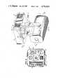
- FIG. 1is an isometric view of the lamp instrument, constructed in accordance with the invention.
- FIG. 2is a sectional view of the base enclosure, taken along line 2--2 of FIG. 1;
- FIG. 3is a sectional view of the lamp instrument taken along line 3--3 of FIG. 1 and illustrating the passageway of the airflow from the base enclosure to the lamp enclosure;
- FIG. 4is a sectional view of the lamp enclosure, taken along line 4--4 of FIG. 1, and illustrating the baffle for directing air on the various lamp apparatus.
- the lamp instrumentcomprises primarily a base enclosure 10 for housing a fan 12 (shown in phantom) and the power supplies and electronics (not shown in FIG. 1).
- the base enclosureprovides the support for mounting the lamp instrument by suitable hangers to overhead beams or rails.
- a hollow forked connecting member 14is provided with a swivel connection 16 to the base enclosure 10, and further includes a pair of hollow spaced-apart arms 18 and 20 depending downwardly therefrom.
- the swivel connection 16enables pan movements.
- a lamp enclosure 22is mounted for pivotal movement between arms 18 and 20 of the connecting member 14 by pivotal connections 24 and 26. Tilt movements of the lamp enclosure 22 are enabled by the pivotal connections 24 and 26.
- the pivotal connections 24 and 26 of the connecting member 14, as well as the swivel connection 16,are provided with passageways for providing the communication of ventilating air from the base enclosure 10 to the lamp enclosure 22.
- the route taken by the airis shown generally by arrows in FIG. 1.
- cool outside airis supplied to the base enclosure 10 through a plurality of inlets 28.
- the inlets 28are grouped in a spaced-apart relationship for a purpose to be described below.
- the airis filtered by filters 30 before being drawn into the base enclosure 10 by a squirrel cage fan 12.
- a case 32 surrounding the fan 12couples the air to a plenum 34.
- the fan case 32is connected to the plenum 34 by a common passageway.
- the connecting member 14is provided with an apertured cylinder 36 for communicating the air to the hollow forked arms 18 and 20.
- the cylinder 36is enclosed by the plenum 34.
- FIG. 2illustrates the arrangement of the equipment within the base enclosure 10 of the lamp instrument.
- the fan 12is located within the base enclosure on a side opposite the air inlets 28.
- circuit modules, generally designated 40, and power supply equipment 42are located between the air inlets 28 and the fan 12. With this placement, cool outside air drawn into the base enclosure 10 by the fan 12 must necessarily pass over the electronic modules 40 and the power supplies 42. The heat generating apparatus is thereby cooled.
- circuit module 40 and power supplies 42After the outside air has passed over the circuit module 40 and power supplies 42, such air is drawn into the fan 12 and communicated to the lamp enclosure 22 in the manner noted above.
- the cooling of the circuit modules 40 and the power supplies 42elevates the air temperature about 20° C. above the ambient air temperature. This cooling extends the life of the electrical components, and the temperature rise of the air does not have a significant effect on the cooling of the high wattage lamp. This can be appreciated as the bulb of the lamp operates at about 250° C.
- the fan 12is enclosed by a case 32, except for an opening 46 at the entrance of the center of the squirrel cage.
- the low air pressure generated within the squirrel cage as a result of its rotationcauses air to be drawn into the fan case 32.
- the airis forced into the plenum 34 surrounding the cylinder 36 of the connecting arm 14. Air is forced from the plenum 34 into the cylinder 36 through holes in the cylinder.
- FIG. 3there is shown a different view of the communication of the air from the fan 12 to the forked connecting member 14.
- a divider 50forms a common wall between the case 32 of the fan 12 and the plenum 34.
- the passage 52 in the divider 50allows air to be transferred from the case 32 into the plenum 34.
- a plurality of holes 54are cut or formed into the connecting arm cylinder 36. Accordingly, air forced from the fan 12 is directed through the holes 54 and into the central part of the cylinder 36. From the central part of the cylinder 36, air is forced into each forked arm 18 and 20 of the connecting member 14.
- FIG. 3also illustrates an electrical cable 56 which is routed through the plenum 34 by a grommet 58, or other strain relief device.
- the cable 56is routed through the top of the cylinder 36 and down through the cylinder. In this manner, electrical cable 56 allows a back-and-forth panning motion of the lamp enclosure 22.
- the plenum 34is constructed of a heavy gauge lightweight metal, such as aluminum, and welded to the bottom of the base enclosure 10.
- the forked connecting member 14, and thus the lamp enclosure 22,is provided with a pan motion about a vertical axis.
- the weight of the member 14 and lamp enclosure 22is supported through a retaining ring 63 secured on cylinder 36.
- the pan motionis made possible by providing a pair of vertically spaced ball bearings 65 and 66 between the cylinder 36 of the connecting member 14 and the base enclosure 10.
- the connecting member 14is fixed to the cylinder 36, while the cylinder 36 is rotatable with respect to the base enclosure 10. With the provision of the two bearings 65 and 66, an additional degree of stability is provided the lamp enclosure 22 with respect to the base enclosure 10, while yet allowing swivel or pan motions.
- the lamp enclosure 22is mounted between the arm 18 and 20 of the forked connecting member 14 for pivotal movement about a horizontal axis. This corresponds to a tilt axis of the lamp facility.
- Fixed to the arms 18 and 20are a pair of tubes 68 and 70 having passageways 72 and 74 formed centrally therethrough.
- the outer races of ball bearings 69 and 71are fixed to the shell 67 of enclosure 22.
- the inner racesare fixed to the tubes to support enclosure 22 for tilt motion.
- the tilt motion of the lamp enclosure 22thereby moves the bearings 69 and 71 with respect to the forked connecting member 14.
- a toothed pulley 84is also fixed to tube 68 for use in effecting the tilting motion of the lamp enclosure 22.
- the portion of the enclosure 22 supporting the bearings 69 and 71 on the lamp enclosure 22form a corresponding pair of ducts 86 and 88.
- These ducts 86 and 88receive the air forced through the forked connecting member arms 18 and 20 and direct the ventilating air to desired apparatus within the lamp enclosure 22.
- the ductsare also integral to the structure of enclosure 22. As noted above, because of the intense beam of light produced by the high wattage lamp, those parts of the lamp facility which operate upon the beam of light to provide color, dimming, etc., become extremely hot, and thereby require cooling.
- FIG. 3there is shown a rotatable color wheel 90 and a gobo wheel 92, each with peripheral elements 94 which are overlappable at a position shown by 96.
- the position 96is the point at which the beam of the high intensity lamp converges and passes through the elements.
- the focal point 96In order to prevent an excessive build up of heat within the wheels 90 and 92, the focal point 96 must be cooled.
- a transverse duct 98is mounted to air duct 88, and is in communication therewith by a port (not shown in FIG. 3).
- transverse duct 98includes an opening 100 proximate the focal point 96, wherein the wheels 90 and 92 receive ventilation air proximate the passage of the light beam. Of course, the opening 100 prevents the light beam from being blocked by the transverse duct.
- the transverse duct 98is shown opening into the side air duct 88.
- a high wattage lamp 101having a base 102 and an envelope 104.
- a thermal shield 106overlies the lamp to thermally insulate a stepper motor 108 of color wheel 90 from the heat of the lamp 101.
- a stepper motor 110is similarly provided to rotate the gobo wheel 92 in increments.
- An objective lens 112is placed in the path of the light beam for providing a focused beam of light.
- a motor 114is connected to the object lens 112 for adjustably moving the lens 112 in an axial direction with respect to the light beam.
- a dimmer 116in the nature of a mechanical iris, is provided for adjusting the intensity of the beam of light produced by the lamp 101.
- a motor 118is operative to adjust the opening within the iris 116 and thereby change the intensity of the light beam.
- a hood 120is connected to the side air duct 88.
- a passageway for airis provided between the side air duct 88 and the hood 120, thereby diverting a portion of the air forced into side air duct 88 toward the high wattage lamp 101. Because the hood 120 is directed to the frontal portion of the lamp 101, a large amount of heat is removed therefrom, as well as from closely located apparatus.
- a baffle 122is formed within the sidewall 124 of side air duct 88 for directing air to cool the base 102 and envelope 104 of the lamp 101. The baffle 122 is essentially a portion of the air duct sidewall 124 cut into a tab and bent outwardly for diverting air within the side air duct 88 toward the lamp 101.
- Side air duct 86opens into the lamp enclosure 22 at position 126. Also, the baffle 128 is provided for directing air toward the object lens 112. Air forced from the side air ducts 86 and 88 into the lamp enclosure 22 is exhausted to the outside by the spotlight opening 38 and rear louvers 39.
- a tilt motor 130is provided with a worm gear 132 for driving a sprocket 134 fixed to shaft 136. Fixed also to the shaft is a pulley 138 which is coupled by a belt 140 to the toothed gear 84. The motor 130 is fixed to the lamp enclosure 22 by a bracket 142. As a result, when motor 130 is energized, the pulley 138 rotates slowly, thereby rotating the housing 22 around the forked connecting member arms 18 and 20.
- an improved lamp enclosure and ventilating systemis disclosed.
- the heat and noise generating equipmentsuch as the power supplies, circuit modules and fan is mounted in the base enclosure of the lamp instrument.
- the fandraws air into the base enclosure and over the electrical equipment to cool it.
- a hollow forked connecting memberis anchored within the base enclosure using bearings for rotation about a vertical axis.
- the lamp enclosurehouses the high wattage lamp and the optical equipment for creating special effects.
- the lamp enclosureis fixed between the arms of the forked connecting member by bearings for providing tilt movements of the lamp enclosure.
- the bearingshave passageways formed therethrough for communicating ventilating air from the base enclosure through the forked connecting member, and to the inner portion of the lamp enclosure.
- Ventilating airis distributed within the lamp enclosure by a pair of ducts, and various hoods and baffles. Air is also forced over the envelope and base of the high wattage lamp, thereby removing a significant amount of heat generated therein. The heated air which is forced through the lamp enclosure and the louvers at the rear of the lamp enclosure is exhausted through the lamp enclosure opening through which the beam of light exits the instrument.
Landscapes
- Engineering & Computer Science (AREA)
- General Engineering & Computer Science (AREA)
- Power Engineering (AREA)
- Arrangement Of Elements, Cooling, Sealing, Or The Like Of Lighting Devices (AREA)
- Non-Portable Lighting Devices Or Systems Thereof (AREA)
Abstract
Description
Claims (21)
Priority Applications (9)
| Application Number | Priority Date | Filing Date | Title |
|---|---|---|---|
| US06/887,371US4701833A (en) | 1986-07-16 | 1986-07-16 | Ventilation system for stage light instrument |
| AU70180/87AAU571135B2 (en) | 1986-07-16 | 1987-03-19 | Ventilation system for stage light instrument |
| CA000533459ACA1284794C (en) | 1986-07-16 | 1987-03-31 | Ventilation system for stage light instrument |
| ES87106116TES2049210T3 (en) | 1986-07-16 | 1987-04-28 | VENTILATION SYSTEM FOR STAGE LIGHTING INSTRUMENTS. |
| AT87106116TATE102326T1 (en) | 1986-07-16 | 1987-04-28 | VENTILATION SYSTEM FOR A STAGE LAMP. |
| DE3789170TDE3789170T2 (en) | 1986-07-16 | 1987-04-28 | Ventilation system for a stage lamp. |
| EP87106116AEP0253080B1 (en) | 1986-07-16 | 1987-04-28 | Ventilation system for stage light instrument |
| JP62128549AJPS6329402A (en) | 1986-07-16 | 1987-05-27 | Stage lighting fixture and enclosure/cooler |
| KR1019870007625AKR910001087B1 (en) | 1986-07-16 | 1987-07-15 | Ventilation system for stage light instrument |
Applications Claiming Priority (1)
| Application Number | Priority Date | Filing Date | Title |
|---|---|---|---|
| US06/887,371US4701833A (en) | 1986-07-16 | 1986-07-16 | Ventilation system for stage light instrument |
Publications (1)
| Publication Number | Publication Date |
|---|---|
| US4701833Atrue US4701833A (en) | 1987-10-20 |
Family
ID=25391003
Family Applications (1)
| Application Number | Title | Priority Date | Filing Date |
|---|---|---|---|
| US06/887,371Expired - LifetimeUS4701833A (en) | 1986-07-16 | 1986-07-16 | Ventilation system for stage light instrument |
Country Status (9)
| Country | Link |
|---|---|
| US (1) | US4701833A (en) |
| EP (1) | EP0253080B1 (en) |
| JP (1) | JPS6329402A (en) |
| KR (1) | KR910001087B1 (en) |
| AT (1) | ATE102326T1 (en) |
| AU (1) | AU571135B2 (en) |
| CA (1) | CA1284794C (en) |
| DE (1) | DE3789170T2 (en) |
| ES (1) | ES2049210T3 (en) |
Cited By (57)
| Publication number | Priority date | Publication date | Assignee | Title |
|---|---|---|---|---|
| US4843528A (en)* | 1986-09-11 | 1989-06-27 | Tasco Limited | Illumination lamp apparatus |
| US4851973A (en)* | 1988-02-29 | 1989-07-25 | Cooper Industries, Inc. | Track lighting fixture with thermal barrier |
| US4935853A (en)* | 1989-02-03 | 1990-06-19 | Collins William J | Motion-controlled light with arc lamp |
| US4937717A (en)* | 1988-06-09 | 1990-06-26 | Betzvog Jr John M | Lighting system for hazardous areas |
| US5034866A (en)* | 1989-12-28 | 1991-07-23 | Altman Stage Lighting Co., Inc. | Multilamp strip light luminaire system |
| US5078039A (en)* | 1988-09-06 | 1992-01-07 | Lightwave Research | Microprocessor controlled lamp flashing system with cooldown protection |
| US5093769A (en)* | 1990-10-04 | 1992-03-03 | Luntsford K Paul | Surgical lighting system |
| US5183331A (en)* | 1991-07-03 | 1993-02-02 | Hubbell Incorporated | Cantilevered spoke mounting for lighting fixture |
| USD340779S (en) | 1990-06-22 | 1993-10-26 | Clay Paky S.R.L. | Special effect light projector |
| US5295056A (en)* | 1992-05-29 | 1994-03-15 | Peck Martin J | Exterior framing projector |
| US5367444A (en)* | 1990-09-06 | 1994-11-22 | Vari-Lite Inc. | Thermal management techniques for lighting instruments |
| US5404283A (en)* | 1992-03-31 | 1995-04-04 | Phoenix Products Company, Inc. | Outdoor framing projector |
| US5934783A (en)* | 1996-05-10 | 1999-08-10 | Matsushita Seiko Co., Ltd. | Ventilating fan/light combination |
| US6095671A (en)* | 1999-01-07 | 2000-08-01 | Hutain; Barry | Actively cooled lighting trim apparatus |
| US6161946A (en)* | 1998-11-09 | 2000-12-19 | Bishop; Christopher B. | Light reflector |
| US6309085B1 (en)* | 2000-04-26 | 2001-10-30 | Best Lighting Products, Inc. | Lamp support for emergency light fixture |
| WO2001098707A1 (en)* | 2000-06-20 | 2001-12-27 | Marumo Electric Co., Ltd. | Lighting device |
| US20030081186A1 (en)* | 2001-10-31 | 2003-05-01 | Hooper Kevin C. | Image projector for use with luminaires |
| US6671005B1 (en)* | 1999-06-21 | 2003-12-30 | Altman Stage Lighting Company | Digital micromirror stage lighting system |
| US20040155597A1 (en)* | 2003-02-07 | 2004-08-12 | Belliveau Richard S. | Method of lamp replacement warning for image projection lighting devices |
| US20040155590A1 (en)* | 2003-02-07 | 2004-08-12 | Belliveau Richard S. | Theatrical fog particle protection system for image projection lighting devices |
| US20050007775A1 (en)* | 2003-07-09 | 2005-01-13 | Belliveau Richard S. | Color modifying effects for image projection lighting devices |
| US20050036316A1 (en)* | 2001-12-21 | 2005-02-17 | De Sisti Lighting S.P.A. | Discharge lamp having integrated ballast support |
| US20060158521A1 (en)* | 2005-01-15 | 2006-07-20 | International Business Machines Corporation | Mechanical and thermal aspects of an enclosure for interactive system components and the like |
| US20070285204A1 (en)* | 2006-06-12 | 2007-12-13 | Production Resource Group, L.L.C. | Moving Light With Removable Circuit Board |
| US7397384B1 (en) | 2005-02-11 | 2008-07-08 | Genlyte Thomas Group, Llc | Track lighting system current limiting device |
| US20080175000A1 (en)* | 2007-01-23 | 2008-07-24 | Johnson Glenn M | Apparatus, system, and method for a ceramic metal halide retrofit kit for a framing projector |
| US7465077B1 (en) | 2004-05-06 | 2008-12-16 | Genlyte Thomas Group, Llc | Retention spring for luminaire reflector |
| US7513675B2 (en) | 2004-05-06 | 2009-04-07 | Genlyte Thomas Group Llc | Modular luminaire system with track and ballast attachment means |
| US20090231852A1 (en)* | 2008-03-17 | 2009-09-17 | Martin Professional A/S | Positioning encoding in a light fixture |
| US20100008080A1 (en)* | 2008-07-14 | 2010-01-14 | Martin Professional A/S | Power module drawer |
| US20100014293A1 (en)* | 2006-09-14 | 2010-01-21 | Koninklijke Philips Electronics N.V. | Lighting unit with rotatable body |
| US7699691B1 (en)* | 2005-05-11 | 2010-04-20 | L-3 Communications Sonoma Eo, Inc. | Cooling system and method for enclosed volume |
| US20100136897A1 (en)* | 2006-09-15 | 2010-06-03 | Bookyu Lee | ventilation cover with a light source |
| US20100157602A1 (en)* | 2005-09-09 | 2010-06-24 | Andrew Tanton Nichols | Lighting |
| US20120281415A1 (en)* | 2007-05-21 | 2012-11-08 | Production Resource Group, L.L.C. | Light Coloring System |
| EP2623856A1 (en)* | 2012-02-06 | 2013-08-07 | Martin Professional A/S | Base-yoke connection for moving head light fixture |
| USD694466S1 (en)* | 2012-09-21 | 2013-11-26 | Martin Professional A/S | Yoke for a lighting fixture |
| USD694462S1 (en)* | 2012-09-21 | 2013-11-26 | Martin Professional A/S | Head for a lighting fixture |
| USD694467S1 (en)* | 2012-09-21 | 2013-11-26 | Martin Professional A/S | Base for a lighting fixture |
| US8770764B2 (en) | 2012-01-16 | 2014-07-08 | Barco Lighting Systems, Inc. | Programmable de-fogger system for a light projector |
| EP2927579A1 (en)* | 2014-04-04 | 2015-10-07 | Martin Professional ApS | Cooling module for led light fixture |
| EP2982906A1 (en)* | 2014-08-08 | 2016-02-10 | CLAY PAKY S.p.A. | Stage light fixture and method for operating said stage light fixture |
| CN105351902A (en)* | 2015-11-30 | 2016-02-24 | 佛山市毅丰电器实业有限公司 | Constant-temperature stage lamp |
| CN105910020A (en)* | 2016-06-20 | 2016-08-31 | 苏州华徕光电仪器有限公司 | Improved LED spot light |
| US20160305637A1 (en)* | 2015-04-17 | 2016-10-20 | Hubbell Incorporated | Emergency exit light |
| TWI607274B (en)* | 2016-11-24 | 2017-12-01 | 台達電子工業股份有限公司 | Projector module and heat dissapation assembly thereof |
| CN107917394A (en)* | 2016-10-10 | 2018-04-17 | 广州市浩洋电子股份有限公司 | A kind of stage lighting supporting rack with water-proof function and there is its waterproof stage lighting |
| CN108167791A (en)* | 2017-12-04 | 2018-06-15 | 广州市浩洋电子股份有限公司 | Cabinet cooling system of stage lamp |
| CN111609341A (en)* | 2019-10-31 | 2020-09-01 | 广州市浩洋电子股份有限公司 | Stage lamp inner loop cooling system |
| CN111649304A (en)* | 2020-03-17 | 2020-09-11 | 广州市明道文化科技集团股份有限公司 | Waterproof stage moving head lamp U type support and have its waterproof stage lamp |
| US11060713B2 (en) | 2019-10-31 | 2021-07-13 | Guangzhou Haoyang Electronic Co., Ltd. | Internal-circulating heat dissipation system for stage light |
| US11339956B2 (en)* | 2019-12-24 | 2022-05-24 | Guangzhou Haoyang Electronic Co., Ltd. | Stage light with speed reducer |
| US20220325883A1 (en)* | 2022-06-28 | 2022-10-13 | Robe Lighting S.R.O. | System and Method for Controlling the Humidity and Pressure in a Luminaire |
| US12085267B2 (en) | 2022-06-28 | 2024-09-10 | Robe Lighting S.R.O. | System and method for controlling the humidity and pressure in a luminaire |
| US20250003582A1 (en)* | 2023-06-29 | 2025-01-02 | Guangzhou Haoyang Electronic Co., Ltd. | Light head with auxiliary heat dissipation and stage light fixture having same |
| US12215848B1 (en)* | 2023-08-31 | 2025-02-04 | Guangzhou Haoyang Electronic Co., Ltd. | Stage light fixture with light head having external heat dissipation |
Families Citing this family (10)
| Publication number | Priority date | Publication date | Assignee | Title |
|---|---|---|---|---|
| JPH0718103Y2 (en)* | 1989-05-30 | 1995-04-26 | 株式会社テック | Spotlight |
| EP0586049B1 (en)* | 1992-09-04 | 1997-09-24 | Vari-Lite, Inc. | Thermal management techniques for lighting instruments |
| KR20040005533A (en)* | 2002-07-10 | 2004-01-16 | (주)헤드벤처엔지니어링 | Main case of stage spotlight |
| JP2007514270A (en)* | 2003-05-14 | 2007-05-31 | コーニンクレッカ フィリップス エレクトロニクス エヌ ヴィ | How to accurately control the cooling process of high power lamps |
| JP2008293860A (en)* | 2007-05-25 | 2008-12-04 | Panasonic Electric Works Co Ltd | Spotlight |
| KR200448220Y1 (en)* | 2008-07-28 | 2010-03-25 | 툴디자인 (주) | Rotary direct and indirect lighting fixtures |
| DE202017101752U1 (en)* | 2017-03-27 | 2018-06-28 | Zumtobel Lighting Gmbh | Luminaire with adjustable light head |
| KR102243102B1 (en)* | 2019-09-11 | 2021-04-22 | (주)영공조명 | Flood light |
| JP7697669B2 (en)* | 2021-08-02 | 2025-06-24 | オーデリック株式会社 | Lighting equipment |
| WO2024061447A1 (en)* | 2022-09-20 | 2024-03-28 | Harman Professional Denmark Aps | A light fixture |
Citations (8)
| Publication number | Priority date | Publication date | Assignee | Title |
|---|---|---|---|---|
| US1301994A (en)* | 1918-06-06 | 1919-04-29 | Charles E Archer | Signal-lamp. |
| US1879600A (en)* | 1929-12-09 | 1932-09-27 | Art Metal Works Inc | Projecting device |
| US1977883A (en)* | 1932-10-20 | 1934-10-23 | Levy Joseph | Lighting fixture support |
| US2108052A (en)* | 1929-09-04 | 1938-02-15 | News Projection Corp | Ink drying means for stock quotation projecting machines |
| US2614457A (en)* | 1950-07-27 | 1952-10-21 | Albert F Weber | Traffic sign projection device |
| US3180981A (en)* | 1961-10-12 | 1965-04-27 | Zeiss Ikon Ag | Air cooled projection lamp |
| US3298277A (en)* | 1963-11-07 | 1967-01-17 | Scharf Erwin | Globular image projector |
| US3959644A (en)* | 1973-10-29 | 1976-05-25 | Feinmechanische Werke Mainz Gmbh | Apparatus for adjustably positioning an air-cooled device |
Family Cites Families (8)
| Publication number | Priority date | Publication date | Assignee | Title |
|---|---|---|---|---|
| DE663242C (en)* | 1938-08-03 | Aeg | Holder for electric headlights | |
| US1382215A (en)* | 1920-06-02 | 1921-06-21 | Himself And Gwylim Anwyl Hughe | Electrical searchlight and other projector |
| US1641301A (en)* | 1921-08-30 | 1927-09-06 | Elmer A Sperry | Searchlight cooling and ventilating means |
| DE2122330C3 (en)* | 1971-05-06 | 1978-11-23 | Original Hanau Quarzlampen Gmbh, 6450 Hanau | Operating light |
| AU5306273A (en)* | 1972-03-07 | 1974-09-12 | Greendale Engineering & Cables Pty. Limited | Improvements in and relating to discharge lighting fittings |
| AU514224B2 (en)* | 1976-07-08 | 1981-01-29 | Ferguson Transformers Pty. Ltd | Housing for electrical components |
| NL7607680A (en)* | 1976-07-12 | 1978-01-16 | Oce Van Der Grinten Nv | DEVICE FOR CONTROLLING THE LIGHT EMISSION OF A GAS DISCHARGE LAMP. |
| US4419716A (en)* | 1983-01-03 | 1983-12-06 | Stephen Koo | Vapor proof housing assembly and system |
- 1986
- 1986-07-16USUS06/887,371patent/US4701833A/ennot_activeExpired - Lifetime
- 1987
- 1987-03-19AUAU70180/87Apatent/AU571135B2/ennot_activeCeased
- 1987-03-31CACA000533459Apatent/CA1284794C/ennot_activeExpired - Lifetime
- 1987-04-28DEDE3789170Tpatent/DE3789170T2/ennot_activeExpired - Fee Related
- 1987-04-28ATAT87106116Tpatent/ATE102326T1/ennot_activeIP Right Cessation
- 1987-04-28ESES87106116Tpatent/ES2049210T3/ennot_activeExpired - Lifetime
- 1987-04-28EPEP87106116Apatent/EP0253080B1/ennot_activeExpired - Lifetime
- 1987-05-27JPJP62128549Apatent/JPS6329402A/enactiveGranted
- 1987-07-15KRKR1019870007625Apatent/KR910001087B1/ennot_activeExpired
Patent Citations (8)
| Publication number | Priority date | Publication date | Assignee | Title |
|---|---|---|---|---|
| US1301994A (en)* | 1918-06-06 | 1919-04-29 | Charles E Archer | Signal-lamp. |
| US2108052A (en)* | 1929-09-04 | 1938-02-15 | News Projection Corp | Ink drying means for stock quotation projecting machines |
| US1879600A (en)* | 1929-12-09 | 1932-09-27 | Art Metal Works Inc | Projecting device |
| US1977883A (en)* | 1932-10-20 | 1934-10-23 | Levy Joseph | Lighting fixture support |
| US2614457A (en)* | 1950-07-27 | 1952-10-21 | Albert F Weber | Traffic sign projection device |
| US3180981A (en)* | 1961-10-12 | 1965-04-27 | Zeiss Ikon Ag | Air cooled projection lamp |
| US3298277A (en)* | 1963-11-07 | 1967-01-17 | Scharf Erwin | Globular image projector |
| US3959644A (en)* | 1973-10-29 | 1976-05-25 | Feinmechanische Werke Mainz Gmbh | Apparatus for adjustably positioning an air-cooled device |
Cited By (88)
| Publication number | Priority date | Publication date | Assignee | Title |
|---|---|---|---|---|
| US4843528A (en)* | 1986-09-11 | 1989-06-27 | Tasco Limited | Illumination lamp apparatus |
| US4851973A (en)* | 1988-02-29 | 1989-07-25 | Cooper Industries, Inc. | Track lighting fixture with thermal barrier |
| US4937717A (en)* | 1988-06-09 | 1990-06-26 | Betzvog Jr John M | Lighting system for hazardous areas |
| US5078039A (en)* | 1988-09-06 | 1992-01-07 | Lightwave Research | Microprocessor controlled lamp flashing system with cooldown protection |
| US4935853A (en)* | 1989-02-03 | 1990-06-19 | Collins William J | Motion-controlled light with arc lamp |
| US5034866A (en)* | 1989-12-28 | 1991-07-23 | Altman Stage Lighting Co., Inc. | Multilamp strip light luminaire system |
| USD340779S (en) | 1990-06-22 | 1993-10-26 | Clay Paky S.R.L. | Special effect light projector |
| US5367444A (en)* | 1990-09-06 | 1994-11-22 | Vari-Lite Inc. | Thermal management techniques for lighting instruments |
| US5093769A (en)* | 1990-10-04 | 1992-03-03 | Luntsford K Paul | Surgical lighting system |
| US5183331A (en)* | 1991-07-03 | 1993-02-02 | Hubbell Incorporated | Cantilevered spoke mounting for lighting fixture |
| US5404283A (en)* | 1992-03-31 | 1995-04-04 | Phoenix Products Company, Inc. | Outdoor framing projector |
| US5295056A (en)* | 1992-05-29 | 1994-03-15 | Peck Martin J | Exterior framing projector |
| US5934783A (en)* | 1996-05-10 | 1999-08-10 | Matsushita Seiko Co., Ltd. | Ventilating fan/light combination |
| US6161946A (en)* | 1998-11-09 | 2000-12-19 | Bishop; Christopher B. | Light reflector |
| US6095671A (en)* | 1999-01-07 | 2000-08-01 | Hutain; Barry | Actively cooled lighting trim apparatus |
| US6671005B1 (en)* | 1999-06-21 | 2003-12-30 | Altman Stage Lighting Company | Digital micromirror stage lighting system |
| US6309085B1 (en)* | 2000-04-26 | 2001-10-30 | Best Lighting Products, Inc. | Lamp support for emergency light fixture |
| US6837596B2 (en) | 2000-06-20 | 2005-01-04 | Marumo Electric Co., Ltd. | Lighting device |
| WO2001098707A1 (en)* | 2000-06-20 | 2001-12-27 | Marumo Electric Co., Ltd. | Lighting device |
| US20030076682A1 (en)* | 2000-06-20 | 2003-04-24 | Tsunemichi Tanaka | Lighting device |
| US6793349B2 (en)* | 2001-10-31 | 2004-09-21 | Rosco Laboratories, Inc. | Image projector for use with luminaires |
| US20030081186A1 (en)* | 2001-10-31 | 2003-05-01 | Hooper Kevin C. | Image projector for use with luminaires |
| US7364324B2 (en)* | 2001-12-21 | 2008-04-29 | De Sisti Lighting S.P.A. | Discharge lamp having integrated ballast support |
| US20050036316A1 (en)* | 2001-12-21 | 2005-02-17 | De Sisti Lighting S.P.A. | Discharge lamp having integrated ballast support |
| US20040155597A1 (en)* | 2003-02-07 | 2004-08-12 | Belliveau Richard S. | Method of lamp replacement warning for image projection lighting devices |
| US6982529B2 (en) | 2003-02-07 | 2006-01-03 | Belliveau Richard S | Method of lamp replacement warning for image projection lighting devices |
| US6988807B2 (en) | 2003-02-07 | 2006-01-24 | Belliveau Richard S | Theatrical fog particle protection system for image projection lighting devices |
| US20060023168A1 (en)* | 2003-02-07 | 2006-02-02 | Belliveau Richard S | Theatrical fog particle protection system for image projection lighting devices |
| US7048383B2 (en) | 2003-02-07 | 2006-05-23 | Belliveau Richard S | Theatrical fog particle protection system for image projection lighting devices |
| US20040155590A1 (en)* | 2003-02-07 | 2004-08-12 | Belliveau Richard S. | Theatrical fog particle protection system for image projection lighting devices |
| US20050007775A1 (en)* | 2003-07-09 | 2005-01-13 | Belliveau Richard S. | Color modifying effects for image projection lighting devices |
| US6971764B2 (en)* | 2003-07-09 | 2005-12-06 | Belliveau Richard S | Color modifying effects for image projection lighting devices |
| US7011429B2 (en)* | 2003-07-09 | 2006-03-14 | Belliveau Richard S | Color modifying effects for image projection lighting devices |
| US20090180301A1 (en)* | 2004-05-06 | 2009-07-16 | Genlyte Thomas Group Llc | Modular luminaire system |
| US7513675B2 (en) | 2004-05-06 | 2009-04-07 | Genlyte Thomas Group Llc | Modular luminaire system with track and ballast attachment means |
| US7914198B2 (en) | 2004-05-06 | 2011-03-29 | Gentyle Thomas Group LLC | Modular luminaire system |
| US7465077B1 (en) | 2004-05-06 | 2008-12-16 | Genlyte Thomas Group, Llc | Retention spring for luminaire reflector |
| US20060158521A1 (en)* | 2005-01-15 | 2006-07-20 | International Business Machines Corporation | Mechanical and thermal aspects of an enclosure for interactive system components and the like |
| US7911351B2 (en) | 2005-02-11 | 2011-03-22 | Genlyte Thomas Group Llc | Track lighting system current limiting device |
| US8144025B2 (en) | 2005-02-11 | 2012-03-27 | Genlyte Thomas Group Llc | Track lighting system current limiting device |
| US20110133671A1 (en)* | 2005-02-11 | 2011-06-09 | Genlyte Thomas Group Llc | Track lighting system current limiting device |
| US7397384B1 (en) | 2005-02-11 | 2008-07-08 | Genlyte Thomas Group, Llc | Track lighting system current limiting device |
| US7699691B1 (en)* | 2005-05-11 | 2010-04-20 | L-3 Communications Sonoma Eo, Inc. | Cooling system and method for enclosed volume |
| US8480259B2 (en)* | 2005-09-09 | 2013-07-09 | Koninklijke Philips Electronics N.V. | Lighting |
| US20100157602A1 (en)* | 2005-09-09 | 2010-06-24 | Andrew Tanton Nichols | Lighting |
| US8622563B2 (en)* | 2006-06-12 | 2014-01-07 | Production Resource Group, Llc | Moving light with removable circuit board |
| US20070285204A1 (en)* | 2006-06-12 | 2007-12-13 | Production Resource Group, L.L.C. | Moving Light With Removable Circuit Board |
| US20100014293A1 (en)* | 2006-09-14 | 2010-01-21 | Koninklijke Philips Electronics N.V. | Lighting unit with rotatable body |
| US20100136897A1 (en)* | 2006-09-15 | 2010-06-03 | Bookyu Lee | ventilation cover with a light source |
| US7597458B2 (en)* | 2007-01-23 | 2009-10-06 | Mountain Springs Holdings, Llc | Apparatus, system, and method for a ceramic metal halide retrofit kit for a framing projector |
| US20080175000A1 (en)* | 2007-01-23 | 2008-07-24 | Johnson Glenn M | Apparatus, system, and method for a ceramic metal halide retrofit kit for a framing projector |
| US9488909B2 (en)* | 2007-05-21 | 2016-11-08 | Production Resource Group, Llc | Light coloring system |
| US20120281415A1 (en)* | 2007-05-21 | 2012-11-08 | Production Resource Group, L.L.C. | Light Coloring System |
| US20090231852A1 (en)* | 2008-03-17 | 2009-09-17 | Martin Professional A/S | Positioning encoding in a light fixture |
| US20100008080A1 (en)* | 2008-07-14 | 2010-01-14 | Martin Professional A/S | Power module drawer |
| US7789525B2 (en)* | 2008-07-14 | 2010-09-07 | Martin Professional A/S | Power module drawer |
| US9188845B2 (en) | 2012-01-16 | 2015-11-17 | Bakco Lighting Systems, Inc. | Programmable de-fogger system for a light projector |
| US8770764B2 (en) | 2012-01-16 | 2014-07-08 | Barco Lighting Systems, Inc. | Programmable de-fogger system for a light projector |
| US9109788B2 (en) | 2012-02-06 | 2015-08-18 | Martin Professional Aps | Base-yoke connection for moving head light fixture |
| CN103244918A (en)* | 2012-02-06 | 2013-08-14 | 马丁专业公司 | Base-yoke connection for moving head light fixture |
| EP2623856A1 (en)* | 2012-02-06 | 2013-08-07 | Martin Professional A/S | Base-yoke connection for moving head light fixture |
| USD694467S1 (en)* | 2012-09-21 | 2013-11-26 | Martin Professional A/S | Base for a lighting fixture |
| USD694466S1 (en)* | 2012-09-21 | 2013-11-26 | Martin Professional A/S | Yoke for a lighting fixture |
| USD694462S1 (en)* | 2012-09-21 | 2013-11-26 | Martin Professional A/S | Head for a lighting fixture |
| EP2927579A1 (en)* | 2014-04-04 | 2015-10-07 | Martin Professional ApS | Cooling module for led light fixture |
| US10072834B2 (en) | 2014-04-04 | 2018-09-11 | Martin Professional Aps | Cooling module for LED light fixture |
| EP2982906A1 (en)* | 2014-08-08 | 2016-02-10 | CLAY PAKY S.p.A. | Stage light fixture and method for operating said stage light fixture |
| US10401013B2 (en)* | 2014-08-08 | 2019-09-03 | Clay Paky S.P.A. | Stage light fixture and method for operating said stage light fixture |
| US10544928B2 (en)* | 2015-04-17 | 2020-01-28 | Hubbell Incorporated | Emergency exit light |
| US20160305637A1 (en)* | 2015-04-17 | 2016-10-20 | Hubbell Incorporated | Emergency exit light |
| US11209149B2 (en) | 2015-04-17 | 2021-12-28 | Hubbell Incorporated | Emergency exit light |
| CN105351902A (en)* | 2015-11-30 | 2016-02-24 | 佛山市毅丰电器实业有限公司 | Constant-temperature stage lamp |
| CN105910020A (en)* | 2016-06-20 | 2016-08-31 | 苏州华徕光电仪器有限公司 | Improved LED spot light |
| CN107917394A (en)* | 2016-10-10 | 2018-04-17 | 广州市浩洋电子股份有限公司 | A kind of stage lighting supporting rack with water-proof function and there is its waterproof stage lighting |
| TWI607274B (en)* | 2016-11-24 | 2017-12-01 | 台達電子工業股份有限公司 | Projector module and heat dissapation assembly thereof |
| CN108167791A (en)* | 2017-12-04 | 2018-06-15 | 广州市浩洋电子股份有限公司 | Cabinet cooling system of stage lamp |
| EP3816508A1 (en)* | 2019-10-31 | 2021-05-05 | Guangzhou Haoyang Electronic Co., Ltd. | Internal-circulating heat dissipation system for stage light |
| WO2021082232A1 (en)* | 2019-10-31 | 2021-05-06 | 广州市浩洋电子股份有限公司 | Circulating heat dissipation system in stage lamp |
| US11060713B2 (en) | 2019-10-31 | 2021-07-13 | Guangzhou Haoyang Electronic Co., Ltd. | Internal-circulating heat dissipation system for stage light |
| CN111609341A (en)* | 2019-10-31 | 2020-09-01 | 广州市浩洋电子股份有限公司 | Stage lamp inner loop cooling system |
| US11339956B2 (en)* | 2019-12-24 | 2022-05-24 | Guangzhou Haoyang Electronic Co., Ltd. | Stage light with speed reducer |
| CN111649304A (en)* | 2020-03-17 | 2020-09-11 | 广州市明道文化科技集团股份有限公司 | Waterproof stage moving head lamp U type support and have its waterproof stage lamp |
| US20220325883A1 (en)* | 2022-06-28 | 2022-10-13 | Robe Lighting S.R.O. | System and Method for Controlling the Humidity and Pressure in a Luminaire |
| US11549679B2 (en)* | 2022-06-28 | 2023-01-10 | Robe Lighting S.R.O. | System and method for controlling the humidity and pressure in a luminaire |
| US12085267B2 (en) | 2022-06-28 | 2024-09-10 | Robe Lighting S.R.O. | System and method for controlling the humidity and pressure in a luminaire |
| US20250003582A1 (en)* | 2023-06-29 | 2025-01-02 | Guangzhou Haoyang Electronic Co., Ltd. | Light head with auxiliary heat dissipation and stage light fixture having same |
| US12320513B2 (en)* | 2023-06-29 | 2025-06-03 | Guangzhou Haoyang Electronic Co., Ltd. | Light head with auxiliary heat dissipation and stage light fixture having same |
| US12215848B1 (en)* | 2023-08-31 | 2025-02-04 | Guangzhou Haoyang Electronic Co., Ltd. | Stage light fixture with light head having external heat dissipation |
Also Published As
| Publication number | Publication date |
|---|---|
| JPS6329402A (en) | 1988-02-08 |
| DE3789170D1 (en) | 1994-04-07 |
| KR880001962A (en) | 1988-04-28 |
| DE3789170T2 (en) | 1994-06-01 |
| AU571135B2 (en) | 1988-03-31 |
| EP0253080B1 (en) | 1994-03-02 |
| JPH0434241B2 (en) | 1992-06-05 |
| AU7018087A (en) | 1988-01-21 |
| CA1284794C (en) | 1991-06-11 |
| EP0253080A3 (en) | 1989-07-19 |
| ATE102326T1 (en) | 1994-03-15 |
| ES2049210T3 (en) | 1994-04-16 |
| KR910001087B1 (en) | 1991-02-23 |
| EP0253080A2 (en) | 1988-01-20 |
Similar Documents
| Publication | Publication Date | Title |
|---|---|---|
| US4701833A (en) | Ventilation system for stage light instrument | |
| US6247830B1 (en) | Heat shield for agricultural light bulb | |
| US4935853A (en) | Motion-controlled light with arc lamp | |
| EP2550482B1 (en) | Lamp cooling system | |
| US4825341A (en) | Cooled lighting apparatus and method | |
| US5091835A (en) | High intensity lamp with improved air flow ventilation | |
| US4922385A (en) | Cooled lighting apparatus and method | |
| US4240133A (en) | Quasimonochromatic light source | |
| CN102257320A (en) | Moving head fixture and cooling module | |
| CN111795355B (en) | Car lamp combining laser and LED | |
| US5172973A (en) | Air cooled housing for light source | |
| WO1988004389A1 (en) | Apparatus for mechanically adjusting lighting fixture azimuth and elevation | |
| US5473523A (en) | Method and means for simultaneously changing the beam angle of all of the light sources in an array of light sources | |
| JP4700734B2 (en) | Cooling system for projector | |
| CN106838841B (en) | Stage lamp | |
| CN109404791B (en) | Intelligent stage lamp with electronic cooling system | |
| CN220169398U (en) | High-power spotlight | |
| JPH0480365B2 (en) | ||
| CA2104989C (en) | Thermal management techniques for lighting instruments | |
| JP4439376B2 (en) | Lighting device | |
| CN222278497U (en) | Lamp cooling system and lamp | |
| CN214890697U (en) | Spotlight capable of automatically adjusting focal length | |
| RU2079773C1 (en) | Lighting fitting | |
| JP6536811B2 (en) | Lighting device | |
| US2785333A (en) | Arc lamp |
Legal Events
| Date | Code | Title | Description |
|---|---|---|---|
| AS | Assignment | Owner name:VARI-LITE, INC., 201 REGAL ROW, DALLAS, TEXAS 7524 Free format text:ASSIGNMENT OF ASSIGNORS INTEREST.;ASSIGNOR:BORNHORST, JAMES M.;REEL/FRAME:004582/0056 Effective date:19860715 Owner name:VARI-LITE, INC.,TEXAS Free format text:ASSIGNMENT OF ASSIGNORS INTEREST;ASSIGNOR:BORNHORST, JAMES M.;REEL/FRAME:004582/0056 Effective date:19860715 | |
| STCF | Information on status: patent grant | Free format text:PATENTED CASE | |
| AS | Assignment | Owner name:VARI-LITE, INC., A CORP. OF DE Free format text:ASSIGNMENT OF ASSIGNORS INTEREST. NOVEMBER 9, 1989 DELAWARE;ASSIGNOR:VARI-LITE, INC., A CORP. OF TX;REEL/FRAME:005302/0578 Effective date:19890808 | |
| FEPP | Fee payment procedure | Free format text:PAYOR NUMBER ASSIGNED (ORIGINAL EVENT CODE: ASPN); ENTITY STATUS OF PATENT OWNER: LARGE ENTITY | |
| FPAY | Fee payment | Year of fee payment:4 | |
| AS | Assignment | Owner name:BROWN BROTHERS HARRIMAN & CO., NEW YORK Free format text:SECURITY INTEREST;ASSIGNOR:VARI-LITE, INC.;REEL/FRAME:006928/0412 Effective date:19940331 | |
| FPAY | Fee payment | Year of fee payment:8 | |
| AS | Assignment | Owner name:VARI-LITE, INC., TEXAS Free format text:SECURITY AGREEMENT;ASSIGNOR:BROWN BROTHER HARRIMAN & CO.;REEL/FRAME:009605/0009 Effective date:19980120 | |
| FEPP | Fee payment procedure | Free format text:PAYOR NUMBER ASSIGNED (ORIGINAL EVENT CODE: ASPN); ENTITY STATUS OF PATENT OWNER: LARGE ENTITY Free format text:PAYER NUMBER DE-ASSIGNED (ORIGINAL EVENT CODE: RMPN); ENTITY STATUS OF PATENT OWNER: LARGE ENTITY | |
| FEPP | Fee payment procedure | Free format text:PAT HLDR NO LONGER CLAIMS SMALL ENT STAT AS SMALL BUSINESS (ORIGINAL EVENT CODE: LSM2); ENTITY STATUS OF PATENT OWNER: LARGE ENTITY | |
| AS | Assignment | Owner name:SUNTRUST BANK, ATLANTA, GEORGIA Free format text:SECURITY INTEREST;ASSIGNOR:WARI-LITE, INC.;REEL/FRAME:009703/0046 Effective date:19981130 | |
| FPAY | Fee payment | Year of fee payment:12 | |
| AS | Assignment | Owner name:VARI-LITE, INC., TEXAS Free format text:RELEASE AND REASSIGNMENT OF SECURITY INTEREST;ASSIGNOR:SUN TRUST BANK;REEL/FRAME:011425/0480 Effective date:20001229 | |
| AS | Assignment | Owner name:VARI-LITE, INC., TEXAS Free format text:RELEASE OF SECURITY AGREEMENT;ASSIGNOR:SUNTRUST BANK, ATLANTA;REEL/FRAME:011658/0738 Effective date:20001229 | |
| AS | Assignment | Owner name:FIRSTAR BANK, NATIONAL ASSOCATION, OHIO Free format text:SECURITY INTEREST;ASSIGNOR:VARI-LITE, INC.;REEL/FRAME:012273/0911 Effective date:20001229 | |
| AS | Assignment | Owner name:VARI-LITE, INC., TEXAS Free format text:SECURITY INTEREST;ASSIGNOR:U.S. BANK NATIONAL ASSOCIATION, F/K/A FIRSTAR BANK, NATIONAL ASSOCIATION;REEL/FRAME:013484/0966 Effective date:20021118 |