US4700716A - Collinear antenna array applicator - Google Patents
Collinear antenna array applicatorDownload PDFInfo
- Publication number
- US4700716A US4700716AUS06/834,199US83419986AUS4700716AUS 4700716 AUS4700716 AUS 4700716AUS 83419986 AUS83419986 AUS 83419986AUS 4700716 AUS4700716 AUS 4700716A
- Authority
- US
- United States
- Prior art keywords
- applicator
- antenna
- array
- conductor
- coaxial
- Prior art date
- Legal status (The legal status is an assumption and is not a legal conclusion. Google has not performed a legal analysis and makes no representation as to the accuracy of the status listed.)
- Expired - Lifetime
Links
- 239000004020conductorSubstances0.000claimsabstractdescription59
- 206010020843HyperthermiaDiseases0.000claimsabstractdescription38
- 230000036031hyperthermiaEffects0.000claimsabstractdescription38
- 238000010438heat treatmentMethods0.000claimsabstractdescription20
- 238000011282treatmentMethods0.000claimsabstractdescription15
- 230000005855radiationEffects0.000claimsdescription15
- 239000003989dielectric materialSubstances0.000claimsdescription5
- 206010028980NeoplasmDiseases0.000abstractdescription36
- 230000005540biological transmissionEffects0.000abstractdescription14
- 239000000463materialSubstances0.000abstractdescription9
- 230000035515penetrationEffects0.000abstractdescription6
- 238000001727in vivoMethods0.000abstractdescription2
- 238000011065in-situ storageMethods0.000abstractdescription2
- 238000000034methodMethods0.000description15
- 210000004027cellAnatomy0.000description10
- 238000000576coating methodMethods0.000description10
- 239000000523sampleSubstances0.000description10
- 210000001519tissueAnatomy0.000description10
- 239000011248coating agentSubstances0.000description8
- 238000001959radiotherapyMethods0.000description8
- 229910000859α-FeInorganic materials0.000description8
- 238000002512chemotherapyMethods0.000description7
- 230000006378damageEffects0.000description7
- 238000009826distributionMethods0.000description7
- 229920001343polytetrafluoroethylenePolymers0.000description7
- BQCADISMDOOEFD-UHFFFAOYSA-NSilverChemical compound[Ag]BQCADISMDOOEFD-UHFFFAOYSA-N0.000description5
- 239000010410layerSubstances0.000description5
- 229910052709silverInorganic materials0.000description5
- 239000004332silverSubstances0.000description5
- 238000002604ultrasonographyMethods0.000description5
- 239000000835fiberSubstances0.000description4
- OAICVXFJPJFONN-UHFFFAOYSA-NPhosphorusChemical compound[P]OAICVXFJPJFONN-UHFFFAOYSA-N0.000description3
- 238000003491arrayMethods0.000description3
- 201000011510cancerDiseases0.000description3
- 230000003247decreasing effectEffects0.000description3
- 239000003814drugSubstances0.000description3
- 229940079593drugDrugs0.000description3
- 230000000694effectsEffects0.000description3
- 230000006870functionEffects0.000description3
- 239000012212insulatorSubstances0.000description3
- 230000003902lesionEffects0.000description3
- 239000003973paintSubstances0.000description3
- 239000004033plasticSubstances0.000description3
- 229920003023plasticPolymers0.000description3
- 229920002401polyacrylamidePolymers0.000description3
- 239000007787solidSubstances0.000description3
- 238000002560therapeutic procedureMethods0.000description3
- 208000003174Brain NeoplasmsDiseases0.000description2
- RYGMFSIKBFXOCR-UHFFFAOYSA-NCopperChemical compound[Cu]RYGMFSIKBFXOCR-UHFFFAOYSA-N0.000description2
- 230000006820DNA synthesisEffects0.000description2
- 241001465754MetazoaSpecies0.000description2
- QVGXLLKOCUKJST-UHFFFAOYSA-Natomic oxygenChemical compound[O]QVGXLLKOCUKJST-UHFFFAOYSA-N0.000description2
- 230000008859changeEffects0.000description2
- 230000001419dependent effectEffects0.000description2
- 238000011161developmentMethods0.000description2
- 230000005684electric fieldEffects0.000description2
- 230000005672electromagnetic fieldEffects0.000description2
- 230000005670electromagnetic radiationEffects0.000description2
- 238000011156evaluationMethods0.000description2
- 238000002594fluoroscopyMethods0.000description2
- 210000001035gastrointestinal tractAnatomy0.000description2
- 238000011835investigationMethods0.000description2
- 210000000244kidney pelvisAnatomy0.000description2
- 229910052751metalInorganic materials0.000description2
- 239000002184metalSubstances0.000description2
- 238000011275oncology therapyMethods0.000description2
- 229910052760oxygenInorganic materials0.000description2
- 239000001301oxygenSubstances0.000description2
- 230000035699permeabilityEffects0.000description2
- 239000006223plastic coatingSubstances0.000description2
- 239000002985plastic filmSubstances0.000description2
- 230000008569processEffects0.000description2
- 238000001356surgical procedureMethods0.000description2
- 238000004861thermometryMethods0.000description2
- 210000000626ureterAnatomy0.000description2
- 210000003932urinary bladderAnatomy0.000description2
- 102100029895Bromodomain-containing protein 4Human genes0.000description1
- 239000004593EpoxySubstances0.000description1
- 101000794024Homo sapiens Bromodomain-containing protein 4Proteins0.000description1
- 206010021143HypoxiaDiseases0.000description1
- 238000012404In vitro experimentMethods0.000description1
- 206010027476MetastasesDiseases0.000description1
- 206010061876ObstructionDiseases0.000description1
- 208000016222Pancreatic diseaseDiseases0.000description1
- 235000015076Shorea robustaNutrition0.000description1
- 244000166071Shorea robustaSpecies0.000description1
- ATJFFYVFTNAWJD-UHFFFAOYSA-NTinChemical compound[Sn]ATJFFYVFTNAWJD-UHFFFAOYSA-N0.000description1
- 210000001015abdomenAnatomy0.000description1
- 239000011358absorbing materialSubstances0.000description1
- 238000010521absorption reactionMethods0.000description1
- 239000000853adhesiveSubstances0.000description1
- 230000001070adhesive effectEffects0.000description1
- 238000013459approachMethods0.000description1
- 239000011324beadSubstances0.000description1
- 230000008901benefitEffects0.000description1
- 210000000013bile ductAnatomy0.000description1
- 210000003445biliary tractAnatomy0.000description1
- 238000001574biopsyMethods0.000description1
- 230000017531blood circulationEffects0.000description1
- 230000036770blood supplyEffects0.000description1
- 210000000988bone and boneAnatomy0.000description1
- 230000005779cell damageEffects0.000description1
- 230000032823cell divisionEffects0.000description1
- 239000011280coal tarSubstances0.000description1
- 230000001427coherent effectEffects0.000description1
- 238000004891communicationMethods0.000description1
- 238000007796conventional methodMethods0.000description1
- 230000000994depressogenic effectEffects0.000description1
- 238000013461designMethods0.000description1
- 238000003745diagnosisMethods0.000description1
- 230000001079digestive effectEffects0.000description1
- 201000010099diseaseDiseases0.000description1
- 208000037265diseases, disorders, signs and symptomsDiseases0.000description1
- 231100000673dose–response relationshipToxicity0.000description1
- 238000004980dosimetryMethods0.000description1
- 230000005520electrodynamicsEffects0.000description1
- 238000011846endoscopic investigationMethods0.000description1
- 238000001839endoscopyMethods0.000description1
- 210000003238esophagusAnatomy0.000description1
- 238000005530etchingMethods0.000description1
- 230000005284excitationEffects0.000description1
- 210000003414extremityAnatomy0.000description1
- 238000001125extrusionMethods0.000description1
- 238000002575gastroscopyMethods0.000description1
- 230000002440hepatic effectEffects0.000description1
- 210000005260human cellAnatomy0.000description1
- 230000007954hypoxiaEffects0.000description1
- 230000006698inductionEffects0.000description1
- 230000028709inflammatory responseEffects0.000description1
- 230000005764inhibitory processEffects0.000description1
- 238000009413insulationMethods0.000description1
- 230000003993interactionEffects0.000description1
- 230000003601intercostal effectEffects0.000description1
- 230000002427irreversible effectEffects0.000description1
- 210000004185liverAnatomy0.000description1
- 230000004807localizationEffects0.000description1
- 208000010949lymph node diseaseDiseases0.000description1
- 230000003211malignant effectEffects0.000description1
- 238000004519manufacturing processMethods0.000description1
- 238000013507mappingMethods0.000description1
- 238000005259measurementMethods0.000description1
- 230000007246mechanismEffects0.000description1
- 239000012528membraneSubstances0.000description1
- 230000009401metastasisEffects0.000description1
- 230000011278mitosisEffects0.000description1
- 230000005404monopoleEffects0.000description1
- 210000003739neckAnatomy0.000description1
- 230000001338necrotic effectEffects0.000description1
- 230000035764nutritionEffects0.000description1
- 235000016709nutritionNutrition0.000description1
- 238000005457optimizationMethods0.000description1
- 238000013021overheatingMethods0.000description1
- 210000000496pancreasAnatomy0.000description1
- 208000024691pancreas diseaseDiseases0.000description1
- 210000004197pelvisAnatomy0.000description1
- -1polytetrafluorethylenePolymers0.000description1
- 235000003784poor nutritionNutrition0.000description1
- 238000010837poor prognosisMethods0.000description1
- 230000002265preventionEffects0.000description1
- 230000002250progressing effectEffects0.000description1
- 210000002307prostateAnatomy0.000description1
- 238000011084recoveryMethods0.000description1
- 210000000664rectumAnatomy0.000description1
- 230000008263repair mechanismEffects0.000description1
- 230000029058respiratory gaseous exchangeEffects0.000description1
- 230000035945sensitivityEffects0.000description1
- 239000002356single layerSubstances0.000description1
- 238000001228spectrumMethods0.000description1
- 238000011351state-of-the-art imaging techniqueMethods0.000description1
- 210000002784stomachAnatomy0.000description1
- 239000011269tarSubstances0.000description1
- 230000001225therapeutic effectEffects0.000description1
- 230000007704transitionEffects0.000description1
- 210000004881tumor cellAnatomy0.000description1
- 238000012285ultrasound imagingMethods0.000description1
- 210000001635urinary tractAnatomy0.000description1
- 238000012800visualizationMethods0.000description1
Images


Classifications
- H—ELECTRICITY
- H01—ELECTRIC ELEMENTS
- H01Q—ANTENNAS, i.e. RADIO AERIALS
- H01Q21/00—Antenna arrays or systems
- H01Q21/06—Arrays of individually energised antenna units similarly polarised and spaced apart
- H01Q21/08—Arrays of individually energised antenna units similarly polarised and spaced apart the units being spaced along or adjacent to a rectilinear path
- A—HUMAN NECESSITIES
- A61—MEDICAL OR VETERINARY SCIENCE; HYGIENE
- A61B—DIAGNOSIS; SURGERY; IDENTIFICATION
- A61B18/00—Surgical instruments, devices or methods for transferring non-mechanical forms of energy to or from the body
- A61B18/18—Surgical instruments, devices or methods for transferring non-mechanical forms of energy to or from the body by applying electromagnetic radiation, e.g. microwaves
- A61B18/1815—Surgical instruments, devices or methods for transferring non-mechanical forms of energy to or from the body by applying electromagnetic radiation, e.g. microwaves using microwaves
- A—HUMAN NECESSITIES
- A61—MEDICAL OR VETERINARY SCIENCE; HYGIENE
- A61B—DIAGNOSIS; SURGERY; IDENTIFICATION
- A61B18/00—Surgical instruments, devices or methods for transferring non-mechanical forms of energy to or from the body
- A61B2018/00053—Mechanical features of the instrument of device
- A61B2018/00273—Anchoring means for temporary attachment of a device to tissue
- A61B2018/00279—Anchoring means for temporary attachment of a device to tissue deployable
- A61B2018/00285—Balloons
- A—HUMAN NECESSITIES
- A61—MEDICAL OR VETERINARY SCIENCE; HYGIENE
- A61B—DIAGNOSIS; SURGERY; IDENTIFICATION
- A61B18/00—Surgical instruments, devices or methods for transferring non-mechanical forms of energy to or from the body
- A61B2018/00571—Surgical instruments, devices or methods for transferring non-mechanical forms of energy to or from the body for achieving a particular surgical effect
- A61B2018/00577—Ablation
- A—HUMAN NECESSITIES
- A61—MEDICAL OR VETERINARY SCIENCE; HYGIENE
- A61B—DIAGNOSIS; SURGERY; IDENTIFICATION
- A61B18/00—Surgical instruments, devices or methods for transferring non-mechanical forms of energy to or from the body
- A61B2018/00636—Sensing and controlling the application of energy
- A61B2018/00696—Controlled or regulated parameters
- A61B2018/00738—Depth, e.g. depth of ablation
- Y—GENERAL TAGGING OF NEW TECHNOLOGICAL DEVELOPMENTS; GENERAL TAGGING OF CROSS-SECTIONAL TECHNOLOGIES SPANNING OVER SEVERAL SECTIONS OF THE IPC; TECHNICAL SUBJECTS COVERED BY FORMER USPC CROSS-REFERENCE ART COLLECTIONS [XRACs] AND DIGESTS
- Y10—TECHNICAL SUBJECTS COVERED BY FORMER USPC
- Y10T—TECHNICAL SUBJECTS COVERED BY FORMER US CLASSIFICATION
- Y10T29/00—Metal working
- Y10T29/49—Method of mechanical manufacture
- Y10T29/49002—Electrical device making
- Y10T29/49117—Conductor or circuit manufacturing
- Y10T29/49123—Co-axial cable
Definitions
- This inventionrelates to a microwave antenna for treatment of deep-seated cancerous tumors by hyperthermia and other biomedical and geological applications involving the use of dielectric heating for treatment of materials.
- hyperthermiainduces an inflammatory response which may also lead to tumor destruction.
- Cancer cellsare more likely to undergo these changes at a particular temperature. This may be due to intrinsic differences, between normal cells and cancerous cells. More likely, the difference is associated with the low pH (acidity), low oxygen content and poor nutrition in tumors as a consequence of decreased blood flow. This is confirmed by the fact that recurrence of tumors in animals, after hyperthermia, is found in the tumor margins; probably as a consequence of better blood supply to those areas.
- Radiotherapychiefly affects cells in mitosis (cell division), while hyperthermia is most effective during the DNA synthesis phase. Heat impairs recovery from sublethal radiation damage. When heat and radiation are given together, or heat prior to radiation, there is thermal enhancement of radiation damage to both normal tissue and tumors. However, if radiation therapy is given prior to hyperthermia, thermal enhancement of radiation damage for tumors is greater than normal tissue.
- a practical hyperthermia applicatormust comply with the following criteria:
- the applicatormust have the ability to focus hyperthermia and quantitate absorbed heat in all areas of the tumor. Studies have shown that very high temperatures (approximately 50° C.) are most effective in cases where this temperature can be achieved. Methods that rely on temperature focusing, rather than on the ability of normal tissues to dissipate heat, allow these temperatures to be achieved.
- the temperature throughout the tumorshould be well-defined and uniform.
- the development of relative cool spots in a non-homogenous tumormay result in failure of cell kill and selection of cells with thermal tolerance (resistance to hyperthermia) within that area. Small differences in temperature may produce large differences in cell kill.
- the techniqueshould enable induction of hyperthermia to a well-defined volume.
- the fall-off of temperature beyond the tumor volumeshould be steep.
- the level of hyperthermiashould be precisely controllable.
- Temperature distribution within the tumor volumeshould be uniform at therapeutic levels.
- the therapist and not the changing characteristics of the heated tumorshould control the temperature within the tumor volume, to avoid overheating a necrotic liquefied tumor center or underheating a well vascularized growing tumor edge.
- Non-invasive hyperthermia applicatorssuch as ultrasound and electromagnetic radiation, are easier to use than invasive techniques, but are limited in depth of penetration. Ultrasound has poor penetration in bone and air. External microwave beam heating is limited by a shallow depth of penetration and the development of standing waves, creating hot and cold spots.
- antenna probesare inserted into the body through the esophagus or rectum, or directly into a tumor using a hollow plastic catheter.
- these probescomprise a quarter-wavelength monopole antenna with frequencies in the 500 MHz to 3 GHz range. These antennae are referred to by workers in the hyperthermia field as a dipole, or a sleeve dipole.
- a folded back quarter wave chokeforms one-half of the antenna length (S. Silver, "Microwave Antenna Theory and Design", Dover Publication, Chapter 8, p 241 and Electromagnetics, Vol. 1, No. 1, January-March 1981, p 58). The latter more nearly approximates a dipole antenna pattern.
- the inventioncomprises an invasive hyperthermia applicator for generating a well-defined uniform pattern of electromagnetic radiation, preferably in the microwave frequency spectrum of 500 megahertz to 5 gigahertz, to produce well-defined temperatures throughout a tumor.
- the applicatoris in the form of an elongate tubular member forming a collinear array of antennae fabricated from a common coaxial transmission line.
- a plurality of antennaei.e., three, are formed from the coaxial transmission line by forming circumferential gaps in the outer conductor of the transmission line.
- the applicatorhas a proximal section and a distal section.
- the three collinear antennasare located in the distal section and a coaxial impedance matching transformer is provided in the proximal section in the form of a circumferential volume of dielectric material with a conductor external to the outer coaxial line.
- a first three half wavelength collinear antennais provided.
- two half wavelength antennasare provided, which are harmonically related to the three half wavelength antenna.
- the combined near field radiation pattern of the three antenna arrayproduces a uniform temperature pattern along the distal section of the applicator at a frequency which produces a minimum in the reflected power inside the coaxial transmission line.
- the circumferential gaps in the outer conductor of the transmission lineresult in a voltage being generated across the gap.
- the gap voltageexcites antenna currents that flow on the outer conductor of the transmission line, while the power flow inside the coaxial transmission line through the center conductor, continues down the line to the next feed gap.
- the gapsthereby result in a radiation aperture.
- the gap spacings from the distal end of the arrayare multiples of one-half of the antenna current wavelength.
- a standing wave of antenna currentdevelops along the entire distal end of the array.
- An outer plastic sheet or coating of dielectric materialis provided around the collinear array, which may optionally include embedded therein, fiber optic sensor bundles, for measuring the temperature at the delivery site.
- a sleeve of lossy, i.e., electromagnetic energy absorbing material, such as ferrite,may be disposed around the outer plastic sheet or coating at a predetermined location or locations along the distal length of the antenna array.
- electromagnetic energy absorbing materialsuch as ferrite
- Some of the electromagnetic energy radiated by the antennais strongly absorbed by the ferrite sleeve which becomes hot and provides a source of localized heat for heating a tumor site.
- This heat sourceis independent of the electromagnetic energy absorbing properties of the tumor and produces hyperthermia range temperatures with significantly less power input than purely electromagnetic energy radiation permits.
- This sleevetends to diminish the severity of the temperature gradient close to the antenna and thus permits more uniform temperatures near the antenna.
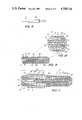
- FIG. 1is a cross-sectional view of the applicator of the present invention showing in solid lines a cross-section of one-half of the far field antenna array pattern resulting from each of the three antenna elements and in dotted lines the near field heating pattern resulting from the super position of the electromagnetic energy pattern generated by the three antenna elements.
- FIG. 2is a cross-sectional view through the applicator 10 of FIG. 1 along the lines 2--2.
- FIG. 3is a cross-sectional view of the applicator of FIG. 1 along the lines 3--3.
- FIG. 4is a cross-sectional view of the applicator of FIG. 1 along the lines 4--4.
- FIG. 5is a cross-sectional view of the applicator of FIG. 1 taken along the lines 5--5.
- FIG. 6is an illustration of an insulated dipole in an ambient medium used to depict the algebraic parameters needed for calculating the optimum transformer parameters.
- FIG. 7is a plot of frequency versus power ratio in decibels for the applicator of the invention.
- FIG. 8is a side view of an optional embodiment of the invention wherein a lossy sleeve 80 is provided over a selected portion of the applicator.
- FIG. 9is a cross-sectional view of an alternate embodiment of the outermost end of the applicator 10 of FIG. 1.
- FIG. 10is an enlarged fragmented view of FIG. 9.
- FIG. 11is a cross-sectional exploded view of a flexible coaxial connector adaptor system 60 for use with the applicator of FIG. 1 shown in the process of being assembled.
- An applicator 10for uniform heating of a tumor with well-defined temperatures throughout the tumor and without hot spots either within or outside the tumor volume, is shown in the form of a collinear array of three antennae fabricated from a coaxial transmission line comprising inner conductor 20 and outer coaxial conductor 16 with an impedance matching element 26.
- the three antennaeare formed by providing circumferential gaps 5 in the outer conductor 16 to expose the dielectric core 18 of the transmission line structure.
- the widths of the gaps 5are about the same size as the distance between center conductor 20 and outer conductor 16.
- Core 18may comprise a suitable solid dielectric insulator, such as PTF (polytetrafluorethylene).
- the gaps 5provide excitation feeds for more remote, i.e., more distal end, antenna sections and result in the equivalent of more than one antenna pattern being generated from the length of the center conductor.
- the electrical lengths of these antenna sectionsare harmonically related to each other.
- a resistor 22is provided at the longitudinal axis of the applicator.
- the collinear array applicator 10 of the present inventionis therefore provided with the appropriate value of resistance about one-quarter wavelength from the end of the distal section.
- a coaxial impedance matching transformeris provided in the form of a dielectric cylinder 26 concentric with and external to the outer conductor 16.
- the dielectric cylinder 26is covered with a metallic cylinder 27 which is electrically shorted to outer conductor 16 at proximal end A.
- a dielectric outer envelope 14extends over the full length of cylinder 27 and distal section B-E.
- the transformerminimizes the reflected power within the feed transmission line and also prevents leakage of antenna currents along the outside of the array applicator 10. By judicious selection of operating parameters, both functions (minimizing reflected power and leakage prevention) occur at approximately the same operating frequency.
- the operating parameters of the coaxial impedance matching transformerare based on the theoretical equations developed by R.
- the transformerprovides a load impedance at the proximal end of the collinear arrays for R.F. power coupled from source 12 via lines 30 and 32 across the inner and outer conductors 20 and 16.
- This load impedanceregulates the antenna current at the feed points or gaps 5 to more nearly match the 50 ohm impedance of the feed transmission line 30 and 32 with the input impedances of the collinear array 10.
- the distal section of applicator 10 of FIG. 1has an overall length B-E of 10 centimeters at a frequency of 915 megahertz. This length is a multiple of one-half of the wavelength of the input frequency, (i.e.
- heating pattern B4is one-half of a plane cut through the full cylindrical near field heating pattern extending from array 10, which is related to the superposition of the three individual far field antenna patterns, B1, B2 and B3, shown in solid lines. If a shorter antenna array is desired, the frequency may be doubled and the length halved. Alternatively, for the same frequency, section C-D can be removed to reduce the length to 8 cm or section B-C can be removed to reduce the length to 4 cm.
- the square of the electric field for the half-wavelength.sup.(1), full wavelength linear.sup.(2) and 3/2 wavelength.sup.(3), antennas in free spaceshown below, provides an indication of the radiated power distribution for the collinear array in lossy material (J. D. Jackson, "Classical Electrodynamics", J. Wiley, 1975, Second Edition, pps 402-403): ##EQU1## wherein ⁇ is measured from the longitudinal axis of the antenna.
- the extreme distal section (C-E) of two series connected half wave antennasradiates 6 dB more power per solid angle than the three half wave length section (B-C).
- the total power radiated by the three half wave length antennais about 60% of the total power delivered to the array (6 cm length compared with 4 cm length). Therefore, forty percent is left over for radiation by the series connected half wave antennae (C-E).
- the 6 dB gain of the 3 ⁇ / 2 sectioncompensates for this loss.
- the resultis a nearly uniform heating pattern along the entire 10 cm length of the distal section B-E of arrav applicator 10.
- the collinear array applicator 10is fabricated using standard AWG (American Wire Gauge) solid or stranded tin plated copper wire (AWG 26 for example) for inner conductor 20.
- AWGAmerican Wire Gauge
- the existing insulation of the copper wiremay be increased in diameter by means of a thin wall plastic tube of PTF to form core 18.
- the outer surface of the tube or core 18is coated with a conductive ink or paint, such as silver, to provide the outer conductor 16 of a two conductor 50 ohm transmission line system. Etching of the tube may be required to insure adhesian of the silver paint.
- the gap location 5are not covered with the conductive ink because they are masked off during the paint application process.
- a uniform PTF coating 14is then applied over the entire distal section B-E.
- the proximal section A-Bis formed in a similar manner, except that prior to application of coating 14, a dielectric sleeve or coating 26 of appropriate dielectric constant and loss tangent, is placed around the conductive ink 16 located at the proximal section.
- the dielectric materialmay preferably be polyacrylamide (See "The Polyacrylamide as a Phantom Material for Electromagnetic Hyperthermia Studies", M. G. Bini, et al., IEEE Transactions of Biomedical Engineering, Vol. BMD-31, No. 3, March 1984) from which the appropriate dielectric constant may be calculated for the proper transformer operation using the criterion that the complex propagation constant, k L of the transformer dielectric is the same as the k L of the distal section.
- a uniform silver ink coatingis then applied over the polyacrylamide material to form a second conductive layer 27.
- This second conductive layer 27is present only over the length of the proximal section It is applied in a manner to create a short circuit to the silver ink outer conductor 16 at proximal end A but leaves an open circuit between it and the outer conductor 16 at point B.
- the outer PTF coating 14is then applied over the proximal section A-B or continued from the distal section.
- This coating 14permits the probe to operate within wide limits of variations of temperature, tissue dielectric constant and electrical conductivity.
- a 10 mil thick coating of PTFpermits the array to maintain a constant heating pattern (ignoring the effects of heat loss or gain by conduction or convection) for a change in the dielectric constant of tissue from 30 to 80 which may occur during heat application.
- fiberoptic thermometry sensors 24may be embedded.
- a sensorsuch as produced by the Luxtron Corporation ("16-Channel Fiberoptic Thermometry System with Multisensor Arrays for Thermal Mapping", Wickersheim et al.) may be appropriately modified for application to the array 10.
- Several linear phosphor sensors 24 about 0.25 mm in diameter (10 mils)may be embedded in the outer dielectric 14. The phosphor sensors 24 utilize the temperature dependence of the fluorescent decay time of the phosphor to determine temperature.
- This techniqueyields a simple, cost-effective multichannel system, which can support a number of small-diameter multi-sensor arrays.
- the proper length of the transformer and its dielectric constantare theoretically determined from the complex propagation constant k L associated with the current on the antenna, in the manner described below in connection with FIG. 6.
- FIG. 6consisting of a central conductor (Region 1) with the half-length "h” and radius "a" surrounded by a cylinder of dielectric which may consist of one (Region 2) or two layers (Region 3)*, with the outer radii "b” and “c", respectively. Outside this insulating sheath is the infinite ambient medium (Region 4) which is a lossy or dielectric.
- the central conductoris sufficiently highly conducting to be well approximated by a perfect conductor.
- the wavenumbers of the dielectric layersare:
- the wavenumber of the lossy dielectric ambient mediumis:
- the general theory of the insulated antennaapplies when the wavenumber of the ambient medium is large compared to that of the insulating sheath and the cross-section of the antenna is electrically small. That is
- H o .sup.(1) (k 4 c) and H 1 .sup.(1) (k 4 c)are zero and first order Hankel functions of the first king.
- n 2e4 2k 2e 2 /k 4 2 .
- Equation (3)is the complex wave number for current on the surface of cylindrical structures embedded in electrically lossy media, such as tumors.
- the input impedance of the bifurcated coaxial line matching transformeris given on page 59 of reference "Embedded Insulated Antennas for Communication and Heating" by R. W. P. King et al., Electromagnetics, Vol. 1, Number 1, January-March 1981.
- the phase constant of the dielectric inside the transformermust match with ⁇ L and ⁇ L d ⁇ /2 gives the required length of the transformer.
- ⁇ Lis the real part of k L of Equation 6.
- the transformer lengthis the length of the proximal section.
- Proper impedance matching of the collinear antenna arrayis therefore dependent on the value of k L .
- a high value of impedancewill exist at the input (Section B). This will effectively isolate the array from the feed line and, with the proper location of the input of the transformer from gap 5, give a collinear array which is properly matched to the 50 ohm feed line.
- FIG. 7shows the ratio of reflected power (P r ) to transmitted power (P t ) in decibels in the coaxial line for a 10 cm long, 3 gap, collinear array of 2 millimeter diameter made in accordance with the invention.
- the frequency fois the frequency which yields the highest value of terminating impedance for the array wherein the elements of the array are harmonically related.
- the collinear array that achieves the uniform heating patternconsists of the elements depicted in the distal section B-E of FIG. 1, wherein the frequency is 915 megahertz.
- the transformer lengthis about 1 centimeter with a PTF dielectric inside the transformer, having a dielectric constant of 40.
- a lossy sleeve 80comprised of ferrite cores or beads formed in the shape of a cylinder with an inner bore may be disposed about the applicator 10 at the distal end thereof.
- the inner diameter of the bore in sleeve 80forms a press fit with the outer diameter of the applicator 10 and is held in place along the longitudinal length of the applicator by a suitable adhesive or other means.
- the sleevemay be used to modify the heat distribution near and around the applicator 10.
- this sleeveprovides a source of highly localized heat without requiring an electromagnetic energy absorption capability of tissue.
- the sleevemay also be used in conjunction with electromagnetic power dissipation in tissue to provide complex heat distribution patterns that conform to the tumor geometry.
- the Curie temperature of ferrite materialdetermines the upper temperatures beyond which the material becomes non-magnetic and hence non-lossy. By selecting an appropriate Curie temperature for the ferrite sleeve, an upper limit on the temperature produced by the sleeve can be established.
- FIGS. 9 and 10An alternate embodiment for the extreme distal end of the applicator is shown in FIGS. 9 and 10 wherein like items in FIG. 1 retain their numeral reference in FIGS. 9 and 10.
- the outer conductor 16 of the antenna arrayis terminated by a radially inwardlv extending ring shown as section 16a and 16b.
- a beam steering resistor 22may be disposed along the longitudinal axis of the antenna in the path of inner conductor 20, as shown.
- an equivalent beam steering resistor 21may be formed as a circular ring embedded in outer insulator 14.
- the inner walls of ring sections 16a and 16bare insulated from resistor 22 or (in the event resistor 22 is not present) from inner conductor 20 by dielectric disk 62.
- the inner conductoris extended radially from the longitudinal axis by disk-like conductor member 18c which is integral with coaxial conductor 18a encased in dielectric 14.
- the collinear applicator array 10may be connected to a commercially available coaxial cable, as shown in FIG. 11, by means of a flexible coaxial connector adaptor 60.
- This type of connectorwill eliminate the need of using expensive commercially available SMA connectors.
- the size of SMA connectorsmay be excessive in diameter for certain application, thereby creating the need of a special connector whose diameter will conform to the diameter of the collinear applicator.
- the adaptorcomprises a laminated metal conductive ring 40 or ferrule having an inner diameter conforming to the outer diameter of the outer conductor 16 of applicator 10 affixed around the outer conductor.
- the outer conductor 16, dielectric core 18 and inner conductor 20 of applicator 10is allowed to extend longitudinally outward from the proximal end of the applicator, with the core 18 extending beyond the outer conductor 16 and the inner conductor 20 extending beyond the core 18.
- An insulative sleeve 64is affixed around the extension of core 18.
- An adaptor pin 42is secured around the extension of inner conductor 20 to provide an enlarged transition from the outer diameter of inner conductor 20 to the outer diameter of standard coaxial cable inner conductors.
- the O.D. of inner conductor 20is preferably about 0.010 inches
- the O.D. of pin 42is 0.018 inches
- the O.D. of sleeve 64is 0.050 inches.
- Pin 42is adapted to be inserted into tapered bore 51 formed within the inner conductor 50 of a standard SMA cable inner conductor having an O.D. of 0.045 inches.
- Dielectric insulator sleeve 64is adapted to extend into coaxial channel 53 around inner conductor 50.
- the metal connector shell of the standard coaxial lineslides over sleeve 64 and abuts ring 40.
- Conductive plastic elastomeric extrusion 44is bonded at one end by conductive epoxy to shell 46 and is held to ring 40 by friction.
- the applicator of the inventioncan be made as described above with an outer diameter of about 0.050 inches. With this small diameter, it can be placed almost anywhere within a patient, with or without fiber optics, using current techniques and equipment, such as endoscopes, CT scanners, ultrasound imaging systems, and fluoroscopy units.
- the currently available state-of-the-art imaging equipmentallows visualization and direct puncture of masses in the neck, abdomen, pelvis, and extremities.
- ultrasonic or CT guidancelong, small diameter needles (18-23 gauge) are easily introduced through the skin and into superficial or deep lesions.
- the applicator probe 10could be easily introduced into these lesions through any number of widely available biopsy needles.
- the same techniques and equipmentcan be used for the relatively non-invasive (i.e., non-surgical) access and treatment of other anatomical sites.
- the gastrointestinal tractspecifically, the biliary system
- endoscopic meansERCP-endoscopic retrograde cannulation of the pancreas
- percutaneouslyby direct intercostal puncture and catherization of the liver and bile ducts for diagnosis and treatment of malignant and benign obstructions (due to hepatic, biliary, pancreatic, and lymph node diseases).
- Other lesions of the GI tract, such as in the stomachare now approached through gastroscopy.
- the relatively large size of the endoscopeeasily allows passage of a probe of the present size.
- Brain tumorsare a potential area for application of the present probe in which hyperthermia may be able to play an immediate and important role. Brain tumors are frequent in the population and histiological types with extremely poor prognosis can be identified. Failure to control local disease and not distant metastasis is by far the major cause of mortality, and clinical trials may be initiated with patients who have failed other modalities (surgery, radiation therapy, chemotherapy). In addition, relatively non-invasive techniques (such as through a burr hole) to guide placement and to monitor results are applicable.
- the lossy sleeve embodiment of FIG. 8is capable of use for dissolving arterial plaque specifically for use in angiosurgery.
Landscapes
- Health & Medical Sciences (AREA)
- Surgery (AREA)
- Life Sciences & Earth Sciences (AREA)
- Biomedical Technology (AREA)
- Medical Informatics (AREA)
- Nuclear Medicine, Radiotherapy & Molecular Imaging (AREA)
- Electromagnetism (AREA)
- Engineering & Computer Science (AREA)
- Physics & Mathematics (AREA)
- Heart & Thoracic Surgery (AREA)
- Otolaryngology (AREA)
- Molecular Biology (AREA)
- Animal Behavior & Ethology (AREA)
- General Health & Medical Sciences (AREA)
- Public Health (AREA)
- Veterinary Medicine (AREA)
- Radiation-Therapy Devices (AREA)
Abstract
Description
k.sub.2 =ω(μ.sub.0 ε.sub.2).sup.1/2 and k.sub.3 =(ω.sub.0 ε.sub.3).sup.1/2,
k.sub.4 =β.sub.4 +iα.sub.4 =ω(μ.sub.0 ε.sub.4).sup.1/2, ε.sub.4 =ε.sub.4 +iσ.sub.4 /ω;
|k.sub.4 /k.sub.2 |.sup.2 >>1;|k.sub.4 k.sub.3 |.sup.2 >>1;(k.sub.2 b).sup.2 <<1;(k.sub.3 c).sup.2 <<1. (1)
Y.sub.o =-(i/2Z.sub.c)tan k.sub.L h. (2b)
k.sub.L =k.sub.2e [ln(c/a)+F].sup.1/2 [ln(c/a)+n.sub.24.sup.2 F].sup.-1/2(6)
Z.sub.c =(μ.sub.o k.sub.L /2πk.sub.2.sup.2)[ln(c/a)+n.sup.2.sub.4 F](7)
Claims (9)
Priority Applications (5)
| Application Number | Priority Date | Filing Date | Title |
|---|---|---|---|
| US06/834,199US4700716A (en) | 1986-02-27 | 1986-02-27 | Collinear antenna array applicator |
| PCT/US1987/002306WO1989002292A1 (en) | 1986-02-27 | 1987-09-09 | Method and apparatus for hyperthermia treatment |
| EP19880900157EP0385978A4 (en) | 1986-02-27 | 1987-09-09 | Method and apparatus for hyperthermia treatment |
| US07/100,465US4776086A (en) | 1986-02-27 | 1987-09-24 | Method and apparatus for hyperthermia treatment |
| US07/550,341US5057106A (en) | 1986-02-27 | 1990-07-09 | Microwave balloon angioplasty |
Applications Claiming Priority (1)
| Application Number | Priority Date | Filing Date | Title |
|---|---|---|---|
| US06/834,199US4700716A (en) | 1986-02-27 | 1986-02-27 | Collinear antenna array applicator |
Related Child Applications (1)
| Application Number | Title | Priority Date | Filing Date |
|---|---|---|---|
| US07/100,465DivisionUS4776086A (en) | 1986-02-27 | 1987-09-24 | Method and apparatus for hyperthermia treatment |
Publications (1)
| Publication Number | Publication Date |
|---|---|
| US4700716Atrue US4700716A (en) | 1987-10-20 |
Family
ID=25266353
Family Applications (2)
| Application Number | Title | Priority Date | Filing Date |
|---|---|---|---|
| US06/834,199Expired - LifetimeUS4700716A (en) | 1986-02-27 | 1986-02-27 | Collinear antenna array applicator |
| US07/100,465Expired - LifetimeUS4776086A (en) | 1986-02-27 | 1987-09-24 | Method and apparatus for hyperthermia treatment |
Family Applications After (1)
| Application Number | Title | Priority Date | Filing Date |
|---|---|---|---|
| US07/100,465Expired - LifetimeUS4776086A (en) | 1986-02-27 | 1987-09-24 | Method and apparatus for hyperthermia treatment |
Country Status (3)
| Country | Link |
|---|---|
| US (2) | US4700716A (en) |
| EP (1) | EP0385978A4 (en) |
| WO (1) | WO1989002292A1 (en) |
Cited By (154)
| Publication number | Priority date | Publication date | Assignee | Title |
|---|---|---|---|---|
| US4776086A (en)* | 1986-02-27 | 1988-10-11 | Kasevich Associates, Inc. | Method and apparatus for hyperthermia treatment |
| US4817635A (en)* | 1987-03-23 | 1989-04-04 | Duke University | Interstitial applicator with cancellation/enhancement gap |
| US4841988A (en)* | 1987-10-15 | 1989-06-27 | Marquette Electronics, Inc. | Microwave hyperthermia probe |
| DE3831016A1 (en)* | 1988-09-12 | 1990-03-15 | Deutsches Krebsforsch | Interstitial hypothermy microwave applicators with optimised distribution of the electromagnetic field |
| EP0372100A1 (en)* | 1986-10-29 | 1990-06-13 | Microthermia Technology, Inc. | Apparatus and a method for destroying cells in tumors and the like |
| WO1990006079A1 (en)* | 1988-11-25 | 1990-06-14 | Sensor Electronics, Inc. | Radiofrequency ablation catheter |
| US4934365A (en)* | 1988-06-30 | 1990-06-19 | Massachusetts Institute Of Technology | Non-invasive hyperthermia method and apparatus |
| US4967765A (en)* | 1988-07-28 | 1990-11-06 | Bsd Medical Corporation | Urethral inserted applicator for prostate hyperthermia |
| DE3926934A1 (en)* | 1989-08-16 | 1991-02-21 | Deutsches Krebsforsch | HYPERTHERMIC MICROWAVE APPLICATOR FOR WARMING A LIMITED ENVIRONMENT IN A DISSIPATIVE MEDIUM |
| US5057106A (en)* | 1986-02-27 | 1991-10-15 | Kasevich Associates, Inc. | Microwave balloon angioplasty |
| US5065819A (en)* | 1990-03-09 | 1991-11-19 | Kai Technologies | Electromagnetic apparatus and method for in situ heating and recovery of organic and inorganic materials |
| US5097845A (en)* | 1987-10-15 | 1992-03-24 | Labthermics Technologies | Microwave hyperthermia probe |
| US5129396A (en)* | 1988-11-10 | 1992-07-14 | Arye Rosen | Microwave aided balloon angioplasty with lumen measurement |
| US5152341A (en)* | 1990-03-09 | 1992-10-06 | Raymond S. Kasevich | Electromagnetic method and apparatus for the decontamination of hazardous material-containing volumes |
| US5220927A (en)* | 1988-07-28 | 1993-06-22 | Bsd Medical Corporation | Urethral inserted applicator for prostate hyperthermia |
| US5234004A (en)* | 1988-11-21 | 1993-08-10 | Technomed International | Method and apparatus for the surgical treatment of tissues by thermal effect, and in particular the prostate, using a urethral microwave-emitting probe means |
| DE4209844A1 (en)* | 1992-03-26 | 1993-09-30 | Sauerwein Isotopen Tech | Radio thermo-therapy applicator for treating tumours - has applicator part inserted in body cavity receiving interchangeable activator for HF heating and radiation source |
| US5249585A (en)* | 1988-07-28 | 1993-10-05 | Bsd Medical Corporation | Urethral inserted applicator for prostate hyperthermia |
| US5301687A (en)* | 1991-06-06 | 1994-04-12 | Trustees Of Dartmouth College | Microwave applicator for transurethral hyperthermia |
| US5330518A (en)* | 1992-03-06 | 1994-07-19 | Urologix, Inc. | Method for treating interstitial tissue associated with microwave thermal therapy |
| US5344435A (en)* | 1988-07-28 | 1994-09-06 | Bsd Medical Corporation | Urethral inserted applicator prostate hyperthermia |
| US5366490A (en)* | 1992-08-12 | 1994-11-22 | Vidamed, Inc. | Medical probe device and method |
| US5369251A (en)* | 1992-09-14 | 1994-11-29 | Kdc Technology Corp. | Microwave interstitial hyperthermia probe |
| US5385544A (en)* | 1992-08-12 | 1995-01-31 | Vidamed, Inc. | BPH ablation method and apparatus |
| US5409453A (en)* | 1992-08-12 | 1995-04-25 | Vidamed, Inc. | Steerable medical probe with stylets |
| US5413588A (en)* | 1992-03-06 | 1995-05-09 | Urologix, Inc. | Device and method for asymmetrical thermal therapy with helical dipole microwave antenna |
| US5421819A (en)* | 1992-08-12 | 1995-06-06 | Vidamed, Inc. | Medical probe device |
| US5435805A (en)* | 1992-08-12 | 1995-07-25 | Vidamed, Inc. | Medical probe device with optical viewing capability |
| US5456662A (en)* | 1993-02-02 | 1995-10-10 | Edwards; Stuart D. | Method for reducing snoring by RF ablation of the uvula |
| US5470308A (en)* | 1992-08-12 | 1995-11-28 | Vidamed, Inc. | Medical probe with biopsy stylet |
| US5496311A (en)* | 1988-10-28 | 1996-03-05 | Boston Scientific Corporation | Physiologic low stress angioplasty |
| US5509929A (en)* | 1988-11-21 | 1996-04-23 | Technomed Medical Systems | Urethral probe and apparatus for the therapeutic treatment of the prostate by thermotherapy |
| US5514131A (en)* | 1992-08-12 | 1996-05-07 | Stuart D. Edwards | Method for the ablation treatment of the uvula |
| US5542915A (en)* | 1992-08-12 | 1996-08-06 | Vidamed, Inc. | Thermal mapping catheter with ultrasound probe |
| US5556377A (en)* | 1992-08-12 | 1996-09-17 | Vidamed, Inc. | Medical probe apparatus with laser and/or microwave monolithic integrated circuit probe |
| US5599295A (en)* | 1992-08-12 | 1997-02-04 | Vidamed, Inc. | Medical probe apparatus with enhanced RF, resistance heating, and microwave ablation capabilities |
| US5628770A (en)* | 1995-06-06 | 1997-05-13 | Urologix, Inc. | Devices for transurethral thermal therapy |
| US5630794A (en)* | 1992-08-12 | 1997-05-20 | Vidamed, Inc. | Catheter tip and method of manufacturing |
| US5672153A (en)* | 1992-08-12 | 1997-09-30 | Vidamed, Inc. | Medical probe device and method |
| US5720719A (en)* | 1992-08-12 | 1998-02-24 | Vidamed, Inc. | Ablative catheter with conformable body |
| US5829519A (en)* | 1997-03-10 | 1998-11-03 | Enhanced Energy, Inc. | Subterranean antenna cooling system |
| US5829528A (en)* | 1997-03-31 | 1998-11-03 | Enhanced Energy, Inc. | Ignition suppression system for down hole antennas |
| RU2121386C1 (en)* | 1993-07-22 | 1998-11-10 | Вячеслав Михайлович Давыдочкин | Method of intracavitary radio-frequency hyperthermia and device intended for its realization |
| US5843144A (en)* | 1995-06-26 | 1998-12-01 | Urologix, Inc. | Method for treating benign prostatic hyperplasia with thermal therapy |
| US5861021A (en)* | 1996-06-17 | 1999-01-19 | Urologix Inc | Microwave thermal therapy of cardiac tissue |
| EP0723468A4 (en)* | 1993-09-17 | 1999-04-28 | Urologix Inc | Gamma matched, helical dipole microwave antenna with tubular-shaped capacitor |
| US5902251A (en)* | 1996-05-06 | 1999-05-11 | Vanhooydonk; Neil C. | Transcervical intrauterine applicator for intrauterine hyperthermia |
| US5938692A (en)* | 1996-03-26 | 1999-08-17 | Urologix, Inc. | Voltage controlled variable tuning antenna |
| US6027313A (en)* | 1997-06-13 | 2000-02-22 | Enhanced Energy, Inc. | Gas assisted fluid delivery system |
| US6047216A (en)* | 1996-04-17 | 2000-04-04 | The United States Of America Represented By The Administrator Of The National Aeronautics And Space Administration | Endothelium preserving microwave treatment for atherosclerosis |
| US6097985A (en)* | 1999-02-09 | 2000-08-01 | Kai Technologies, Inc. | Microwave systems for medical hyperthermia, thermotherapy and diagnosis |
| WO2000047281A1 (en) | 1999-02-09 | 2000-08-17 | Kai Technologies, Inc. | Microwave devices for medical hyperthermia, thermotherapy and diagnosis |
| WO2000047282A1 (en) | 1999-02-09 | 2000-08-17 | Kai Technologies, Inc. | Microwave antennas for medical hyperthermia, thermotherapy and diagnosis |
| WO2001012261A1 (en) | 1999-08-19 | 2001-02-22 | Kai Technologies, Inc. | Microwave devices for medical hyperthermia, thermotherapy and diagnosis |
| US20030088242A1 (en)* | 2001-11-02 | 2003-05-08 | Mani Prakash | High-strength microwave antenna assemblies |
| US20030109862A1 (en)* | 2001-11-02 | 2003-06-12 | Mani Prakash | High-strength microwave antenna assemblies and methods of use |
| US6640138B1 (en) | 2000-08-04 | 2003-10-28 | Thermatrx, Inc. | Apparatus and method for heat treatment of tissue |
| US6740108B1 (en) | 2001-04-05 | 2004-05-25 | Urologix, Inc. | Thermal treatment catheter having preferential asymmetrical heating pattern |
| US20040168692A1 (en)* | 2000-02-18 | 2004-09-02 | Thomas Fogarty | Device for accurately marking tissue |
| US20040228650A1 (en)* | 2003-05-09 | 2004-11-18 | Takashi Saito | Image forming apparatus |
| GB2403148A (en)* | 2003-06-23 | 2004-12-29 | Microsulis Ltd | Radiation Applicator |
| US20050024284A1 (en)* | 2003-07-14 | 2005-02-03 | Halek James Michael | Microwave demulsification of hydrocarbon emulsion |
| US20050149010A1 (en)* | 2003-07-18 | 2005-07-07 | Vivant Medical, Inc. | Devices and methods for cooling microwave antennas |
| RU2262961C1 (en)* | 2004-05-05 | 2005-10-27 | Рязанская государственная сельскохозяйственная академия им. профессора П.А. Костычева | Irradiator for carrying out radio frequency therapy of abdominal organs |
| US6976986B2 (en) | 2000-04-12 | 2005-12-20 | Afx, Inc. | Electrode arrangement for use in a medical instrument |
| US7033352B1 (en) | 2000-01-18 | 2006-04-25 | Afx, Inc. | Flexible ablation instrument |
| US7052491B2 (en) | 1998-10-23 | 2006-05-30 | Afx, Inc. | Vacuum-assisted securing apparatus for a microwave ablation instrument |
| US7089064B2 (en) | 1998-05-08 | 2006-08-08 | Ams Research Corporation | Therapeutic prostatic thermotherapy |
| US7099717B2 (en) | 2002-01-03 | 2006-08-29 | Afx Inc. | Catheter having improved steering |
| US20060259024A1 (en)* | 2005-05-10 | 2006-11-16 | Roman Turovskiy | Reinforced high strength microwave antenna |
| US20060289528A1 (en)* | 2003-03-26 | 2006-12-28 | Heng-Mao Chiu | Microwave antenna for medical ablation |
| US7160292B2 (en) | 1999-06-17 | 2007-01-09 | Vivant Medical, Inc. | Needle kit and method for microwave ablation, track coagulation, and biopsy |
| WO2007024942A2 (en) | 2005-08-23 | 2007-03-01 | Wisconsin Alumni Research Foundation | Floating sleeve microwave antenna for tumor ablation |
| US20070049918A1 (en)* | 2005-08-24 | 2007-03-01 | Van Der Weide Daniel W | Microwave device for vascular ablation |
| US7192427B2 (en) | 2002-02-19 | 2007-03-20 | Afx, Inc. | Apparatus and method for assessing transmurality of a tissue ablation |
| US7197363B2 (en) | 2002-04-16 | 2007-03-27 | Vivant Medical, Inc. | Microwave antenna having a curved configuration |
| US7226446B1 (en) | 1999-05-04 | 2007-06-05 | Dinesh Mody | Surgical microwave ablation assembly |
| US20070137852A1 (en)* | 2005-12-20 | 2007-06-21 | Considine Brian C | Apparatus for extraction of hydrocarbon fuels or contaminants using electrical energy and critical fluids |
| US20070137858A1 (en)* | 2005-12-20 | 2007-06-21 | Considine Brian C | Method for extraction of hydrocarbon fuels or contaminants using electrical energy and critical fluids |
| US20070185554A1 (en)* | 2006-02-07 | 2007-08-09 | Angiodynamics, Inc. | Interstitial microwave system and method for thermal treatment of diseases |
| US7303560B2 (en) | 2000-12-29 | 2007-12-04 | Afx, Inc. | Method of positioning a medical instrument |
| US20070282319A1 (en)* | 2006-03-24 | 2007-12-06 | Micrablate, Inc. | Center fed dipole for use with tissue ablation systems, devices and methods |
| US20080033424A1 (en)* | 2006-03-24 | 2008-02-07 | Micrablate | Transmission line with heat transfer ability |
| US20080045938A1 (en)* | 2006-07-14 | 2008-02-21 | Micrablate | Energy delivery systems and uses thereof |
| US7346399B2 (en) | 1999-05-28 | 2008-03-18 | Afx, Inc. | Monopole tip for ablation catheter |
| US20080140062A1 (en)* | 2004-07-16 | 2008-06-12 | Nigel Cronin | Microwave Applicator |
| US20080300611A1 (en)* | 2007-05-29 | 2008-12-04 | Houser Kevin L | Ultrasonic surgical system |
| US7468042B2 (en) | 2002-04-16 | 2008-12-23 | Vivant Medical, Inc. | Localization element with energized tip |
| US20090084581A1 (en)* | 2007-09-28 | 2009-04-02 | Vivant Medical, Inc. | Cable Stand-Off |
| US20090295674A1 (en)* | 2008-05-29 | 2009-12-03 | Kenlyn Bonn | Slidable Choke Microwave Antenna |
| US20100030207A1 (en)* | 2006-10-10 | 2010-02-04 | Medical Device Innovations Limited | Surgical antenna |
| US20100049185A1 (en)* | 2008-08-25 | 2010-02-25 | Vivant Medical, Inc. | Microwave Antenna Assembly Having a Dielectric Body Portion With Radial Partitions of Dielectric Material |
| US20100078163A1 (en)* | 2008-09-26 | 2010-04-01 | Conocophillips Company | Process for enhanced production of heavy oil using microwaves |
| US20100087808A1 (en)* | 2008-10-03 | 2010-04-08 | Vivant Medical, Inc. | Combined Frequency Microwave Ablation System, Devices and Methods of Use |
| US20100094272A1 (en)* | 2008-10-13 | 2010-04-15 | Vivant Medical, Inc. | Antenna Assemblies for Medical Applications |
| US20100097284A1 (en)* | 2008-10-17 | 2010-04-22 | Vivant Medical, Inc. | Choked Dielectric Loaded Tip Dipole Microwave Antenna |
| US20100121319A1 (en)* | 2008-11-10 | 2010-05-13 | Microcube, Llc | Methods and devices for applying energy to bodily tissues |
| US20100137857A1 (en)* | 2008-10-21 | 2010-06-03 | Microcube, Limited Liability Corporation | Methods and devices for applying energy to bodily tissues |
| US20100305559A1 (en)* | 2009-05-27 | 2010-12-02 | Vivant Medical, Inc. | Narrow Gauge High Strength Choked Wet Tip Microwave Ablation Antenna |
| US20110004205A1 (en)* | 2008-10-21 | 2011-01-06 | Chu Chun Yiu | Methods and devices for delivering microwave energy |
| WO2011001408A1 (en)* | 2009-07-03 | 2011-01-06 | Total S.A. | Method for extracting hydrocarbons by in-situ electromagnetic heating of an underground formation |
| US20110005748A1 (en)* | 2009-03-16 | 2011-01-13 | Saudi Arabian Oil Company | Recovering heavy oil through the use of microwave heating in horizontal wells |
| US20110077636A1 (en)* | 2009-09-29 | 2011-03-31 | Vivant Medical, Inc. | Management of Voltage Standing Wave Ratio at Skin Surface During Microwave Ablation |
| US20110160717A1 (en)* | 2006-07-14 | 2011-06-30 | Neuwave Medical, Inc. | Energy delivery systems and uses thereof |
| US20110196356A1 (en)* | 2009-09-15 | 2011-08-11 | Ceramoptec Industries Inc. | Ablative/coagulative urological treatment device and method |
| US7998139B2 (en) | 2007-04-25 | 2011-08-16 | Vivant Medical, Inc. | Cooled helical antenna for microwave ablation |
| US20110238060A1 (en)* | 2004-04-29 | 2011-09-29 | Neuwave Medical, Inc. | Microwave surgical device |
| US8068921B2 (en) | 2006-09-29 | 2011-11-29 | Vivant Medical, Inc. | Microwave antenna assembly and method of using the same |
| US8188435B2 (en) | 2010-06-03 | 2012-05-29 | Tyco Healthcare Group Lp | Specific absorption rate measurement and energy-delivery device characterization using thermal phantom and image analysis |
| US8292880B2 (en) | 2007-11-27 | 2012-10-23 | Vivant Medical, Inc. | Targeted cooling of deployable microwave antenna |
| US8317703B2 (en) | 2011-02-17 | 2012-11-27 | Vivant Medical, Inc. | Energy-delivery device including ultrasound transducer array and phased antenna array, and methods of adjusting an ablation field radiating into tissue using same |
| US8353901B2 (en) | 2007-05-22 | 2013-01-15 | Vivant Medical, Inc. | Energy delivery conduits for use with electrosurgical devices |
| US8376948B2 (en) | 2011-02-17 | 2013-02-19 | Vivant Medical, Inc. | Energy-delivery device including ultrasound transducer array and phased antenna array |
| US8394092B2 (en) | 2009-11-17 | 2013-03-12 | Vivant Medical, Inc. | Electromagnetic energy delivery devices including an energy applicator array and electrosurgical systems including same |
| US8464789B2 (en) | 2008-09-26 | 2013-06-18 | Conocophillips Company | Process for enhanced production of heavy oil using microwaves |
| ITMO20120041A1 (en)* | 2012-02-17 | 2013-08-18 | Hs Hospital Service Spa | MICROWAVE DEVICE FOR FABRIC EXTRACTION |
| US20130261640A1 (en)* | 2012-03-28 | 2013-10-03 | Samsung Electronics Co., Ltd. | Surgical robot system and method of controlling the same |
| US8679108B2 (en) | 2009-02-20 | 2014-03-25 | Covidien Lp | Leaky-wave antennas for medical applications |
| US8689865B2 (en) | 2008-09-26 | 2014-04-08 | Conocophillips Company | Process for enhanced production of heavy oil using microwaves |
| US8720549B2 (en) | 2008-09-26 | 2014-05-13 | Conocophillips Company | Process for enhanced production of heavy oil using microwaves |
| US8720548B2 (en) | 2008-09-26 | 2014-05-13 | Conocophillips Company | Process for enhanced production of heavy oil using microwaves |
| US8720550B2 (en) | 2008-09-26 | 2014-05-13 | Conocophillips Company | Process for enhanced production of heavy oil using microwaves |
| US8720547B2 (en) | 2008-09-26 | 2014-05-13 | Conocophillips Company | Process for enhanced production of heavy oil using microwaves |
| US8832927B2 (en) | 2009-03-10 | 2014-09-16 | Covidien Lp | Method of manufacturing surgical antennas |
| US8905127B2 (en) | 2008-09-26 | 2014-12-09 | Conocophillips Company | Process for enhanced production of heavy oil using microwaves |
| US9023024B2 (en) | 2007-06-20 | 2015-05-05 | Covidien Lp | Reflective power monitoring for microwave applications |
| US9119649B2 (en) | 2009-07-28 | 2015-09-01 | Neuwave Medical, Inc. | Energy delivery systems and uses thereof |
| US20150285904A1 (en)* | 2014-04-04 | 2015-10-08 | Texas Instruments Incorporated | Antenna configuration for parking assist radar |
| US9192438B2 (en) | 2011-12-21 | 2015-11-24 | Neuwave Medical, Inc. | Energy delivery systems and uses thereof |
| US9241762B2 (en) | 2010-06-03 | 2016-01-26 | Covidien Lp | Specific absorption rate measurement and energy-delivery device characterization using image analysis |
| US9377367B2 (en) | 2010-06-03 | 2016-06-28 | Covidien Lp | Specific absorption rate measurement and energy-delivery device characterization using thermal phantom and image analysis |
| US9468492B2 (en) | 2010-06-03 | 2016-10-18 | Covidien Lp | Specific absorption rate measurement and energy-delivery device characterization using image analysis |
| US20170016866A1 (en)* | 2015-07-13 | 2017-01-19 | International Business Machines Corporation | Reconfigurable gas sensor architecture with a high sensitivity at low temperatures |
| US9615882B2 (en) | 2008-10-21 | 2017-04-11 | Microcube, Llc | Methods and devices for applying energy to bodily tissues |
| US9861440B2 (en) | 2010-05-03 | 2018-01-09 | Neuwave Medical, Inc. | Energy delivery systems and uses thereof |
| US10342614B2 (en) | 2004-04-29 | 2019-07-09 | Wisconsin Alumni Research Foundation | Triaxial antenna for microwave tissue ablation |
| US10531917B2 (en) | 2016-04-15 | 2020-01-14 | Neuwave Medical, Inc. | Systems and methods for energy delivery |
| EP3466364A4 (en)* | 2016-05-24 | 2020-02-19 | Surgnova Healthcare Technologies (Zhejiang) Co.,Ltd. | Antenna assembly for microwave ablation and microwave ablation needle using same |
| CN111432724A (en)* | 2017-10-05 | 2020-07-17 | 美国贝鲁特大学 | Novel non-invasive biological, chemical marker and tracer monitoring device for monitoring blood containing glucose using adaptive radio frequency circuit and antenna design |
| US10952792B2 (en) | 2015-10-26 | 2021-03-23 | Neuwave Medical, Inc. | Energy delivery systems and uses thereof |
| EP3745975A4 (en)* | 2018-02-02 | 2021-11-03 | Varian Medical Systems, Inc. | MICROWAVE ABLATION ANTENNAS |
| EP3852495A4 (en)* | 2018-09-14 | 2021-11-10 | Panasonic Intellectual Property Management Co., Ltd. | MICROWAVE HEATER |
| US11219484B2 (en) | 2008-10-21 | 2022-01-11 | Microcube, Llc | Methods and devices for delivering microwave energy |
| US20220026119A1 (en)* | 2020-07-25 | 2022-01-27 | Choon Sae Lee | Electromagnetic cooling and heating |
| US11291503B2 (en) | 2008-10-21 | 2022-04-05 | Microcube, Llc | Microwave treatment devices and methods |
| US20220142700A1 (en)* | 2019-03-01 | 2022-05-12 | Riverrfield Inc. | Surgical instrument for surgical assist robot |
| US11399915B2 (en) | 2013-03-15 | 2022-08-02 | TriAgenics, Inc. | Therapeutic tooth bud ablation |
| US11583337B2 (en)* | 2019-06-06 | 2023-02-21 | TriAgenics, Inc. | Ablation probe systems |
| US11672596B2 (en) | 2018-02-26 | 2023-06-13 | Neuwave Medical, Inc. | Energy delivery devices with flexible and adjustable tips |
| US11786303B2 (en)* | 2021-03-19 | 2023-10-17 | Quicker-Instrument Inc. | Microwave ablation probe |
| US11832879B2 (en) | 2019-03-08 | 2023-12-05 | Neuwave Medical, Inc. | Systems and methods for energy delivery |
| US11864961B2 (en) | 2013-03-15 | 2024-01-09 | TriAgenics, Inc. | Therapeutic tooth bud ablation |
| US12076198B2 (en) | 2009-05-11 | 2024-09-03 | TriAgenics, Inc. | Therapeutic tooth bud ablation |
| US12239367B2 (en) | 2019-06-25 | 2025-03-04 | Microcube, Llc | Methods and devices for generating and delivering shaped microwave fields |
Families Citing this family (51)
| Publication number | Priority date | Publication date | Assignee | Title |
|---|---|---|---|---|
| US4961422A (en)* | 1983-01-21 | 1990-10-09 | Marchosky J Alexander | Method and apparatus for volumetric interstitial conductive hyperthermia |
| IL92332A0 (en)* | 1988-11-21 | 1990-07-26 | Technomed Int Sa | Apparatus for the surgical treatment of tissues by hyperthermia,particularly the prostate,equipped with heat-protection means preferably comprising means forming radioreflecting screen |
| US5085931A (en)* | 1989-01-26 | 1992-02-04 | Minnesota Mining And Manufacturing Company | Microwave absorber employing acicular magnetic metallic filaments |
| US4998932A (en)* | 1989-05-03 | 1991-03-12 | Amt Inc. | Catheter with distally located integrated circuit radiation generator |
| US5627584A (en)* | 1991-01-17 | 1997-05-06 | Olympus Optical Co., Ltd. | Endoscope system with centralized control of associated peripheral equipment |
| US5486161A (en)* | 1993-02-02 | 1996-01-23 | Zomed International | Medical probe device and method |
| GB9315473D0 (en)* | 1993-07-27 | 1993-09-08 | Chemring Ltd | Treatment apparatus |
| US6958062B1 (en) | 1993-11-08 | 2005-10-25 | Rita Medical Systems, Inc. | Multiple antenna ablation apparatus and method |
| US5599346A (en)* | 1993-11-08 | 1997-02-04 | Zomed International, Inc. | RF treatment system |
| US6071280A (en)* | 1993-11-08 | 2000-06-06 | Rita Medical Systems, Inc. | Multiple electrode ablation apparatus |
| US5458597A (en)* | 1993-11-08 | 1995-10-17 | Zomed International | Device for treating cancer and non-malignant tumors and methods |
| US5472441A (en)* | 1993-11-08 | 1995-12-05 | Zomed International | Device for treating cancer and non-malignant tumors and methods |
| US5928229A (en)* | 1993-11-08 | 1999-07-27 | Rita Medical Systems, Inc. | Tumor ablation apparatus |
| US6090105A (en)* | 1995-08-15 | 2000-07-18 | Rita Medical Systems, Inc. | Multiple electrode ablation apparatus and method |
| US6689127B1 (en) | 1995-08-15 | 2004-02-10 | Rita Medical Systems | Multiple antenna ablation apparatus and method with multiple sensor feedback |
| US6059780A (en)* | 1995-08-15 | 2000-05-09 | Rita Medical Systems, Inc. | Multiple antenna ablation apparatus and method with cooling element |
| US5913855A (en)* | 1995-08-15 | 1999-06-22 | Rita Medical Systems, Inc. | Multiple antenna ablation apparatus and method |
| US6080150A (en)* | 1995-08-15 | 2000-06-27 | Rita Medical Systems, Inc. | Cell necrosis apparatus |
| US6132425A (en)* | 1995-08-15 | 2000-10-17 | Gough; Edward J. | Cell necrosis apparatus |
| US5925042A (en)* | 1995-08-15 | 1999-07-20 | Rita Medical Systems, Inc. | Multiple antenna ablation apparatus and method |
| US5951547A (en)* | 1995-08-15 | 1999-09-14 | Rita Medical Systems, Inc. | Multiple antenna ablation apparatus and method |
| US5980517A (en)* | 1995-08-15 | 1999-11-09 | Rita Medical Systems, Inc. | Cell necrosis apparatus |
| US6135971A (en)* | 1995-11-09 | 2000-10-24 | Brigham And Women's Hospital | Apparatus for deposition of ultrasound energy in body tissue |
| US5987360A (en)* | 1996-05-03 | 1999-11-16 | Urologix, Inc. | Axial preferential thermal therapy |
| US6104959A (en) | 1997-07-31 | 2000-08-15 | Microwave Medical Corp. | Method and apparatus for treating subcutaneous histological features |
| US20070066972A1 (en)* | 2001-11-29 | 2007-03-22 | Medwaves, Inc. | Ablation catheter apparatus with one or more electrodes |
| US7070595B2 (en)* | 1998-12-14 | 2006-07-04 | Medwaves, Inc. | Radio-frequency based catheter system and method for ablating biological tissues |
| GB9904373D0 (en) | 1999-02-25 | 1999-04-21 | Microsulis Plc | Radiation applicator |
| US7232433B1 (en) | 1999-09-22 | 2007-06-19 | Siemens Medical Solutions Usa, Inc. | Medical diagnostic ultrasound catheter with dielectric isolation |
| CN100508910C (en)* | 2001-11-29 | 2009-07-08 | 麦迪威公司 | Radio frequency based catheter system with improved deflection and steering mechanism |
| US7467015B2 (en)* | 2004-04-29 | 2008-12-16 | Neuwave Medical, Inc. | Segmented catheter for tissue ablation |
| US7150095B2 (en)* | 2004-08-31 | 2006-12-19 | Fujitsu Limited | Method for manufacturing probe needle, method for manufacturing probe card, and probe card |
| US7410485B1 (en) | 2005-01-14 | 2008-08-12 | The United States Of America As Represented By The Administrator Of The National Aeronautics And Space Administration | Directional microwave applicator and methods |
| EP2767308B1 (en) | 2007-04-19 | 2016-04-13 | Miramar Labs, Inc. | Devices, and systems for non-invasive delivery of microwave therapy |
| BRPI0810066A2 (en) | 2007-04-19 | 2015-05-05 | The Foundry Inc | Systems and methods for creating an effect using microwave energy for specific tissue |
| EP3391844A1 (en) | 2007-04-19 | 2018-10-24 | Miramar Labs, Inc. | Apparatus for reducing sweat production |
| WO2008131306A1 (en) | 2007-04-19 | 2008-10-30 | The Foundry, Inc. | Systems and methods for creating an effect using microwave energy to specified tissue |
| US20090082762A1 (en)* | 2007-09-20 | 2009-03-26 | Ormsby Theodore C | Radio frequency energy transmission device for the ablation of biological tissues |
| EP2762199B1 (en) | 2007-12-12 | 2018-03-14 | Miramar Labs, Inc. | Systems, apparatus, methods and procedures for the noninvasive treatment of tissue using microwave energy |
| KR101826243B1 (en) | 2007-12-12 | 2018-02-06 | 미라마 랩스 인코포레이티드 | Systems, apparatus, methods and procedures for the noninvasive treatment of tissue using microwave energy |
| EP2271276A4 (en) | 2008-04-17 | 2013-01-23 | Miramar Labs Inc | Systems, apparatus, methods and procedures for the noninvasive treatment of tissue using microwave energy |
| US8133222B2 (en)* | 2008-05-28 | 2012-03-13 | Medwaves, Inc. | Tissue ablation apparatus and method using ultrasonic imaging |
| US8679106B2 (en)* | 2008-07-01 | 2014-03-25 | Medwaves, Inc. | Angioplasty and tissue ablation apparatus and method |
| US20110009804A1 (en)* | 2009-07-08 | 2011-01-13 | Tyco Healthcare Group Lp | Method and System for Delivering a Medicant |
| US8328800B2 (en)* | 2009-08-05 | 2012-12-11 | Vivant Medical, Inc. | Directive window ablation antenna with dielectric loading |
| US8328799B2 (en)* | 2009-08-05 | 2012-12-11 | Vivant Medical, Inc. | Electrosurgical devices having dielectric loaded coaxial aperture with distally positioned resonant structure |
| US8328801B2 (en)* | 2009-08-17 | 2012-12-11 | Vivant Medical, Inc. | Surface ablation antenna with dielectric loading |
| WO2011066445A2 (en)* | 2009-11-30 | 2011-06-03 | Medwaves, Inc. | Radio frequency ablation system with tracking sensor |
| RU2504342C2 (en)* | 2011-07-08 | 2014-01-20 | Михаил Анатольевич Коневский | Method of treating volume neoplasms of brain |
| US9314301B2 (en) | 2011-08-01 | 2016-04-19 | Miramar Labs, Inc. | Applicator and tissue interface module for dermatological device |
| US10779885B2 (en) | 2013-07-24 | 2020-09-22 | Miradry. Inc. | Apparatus and methods for the treatment of tissue using microwave energy |
Citations (9)
| Publication number | Priority date | Publication date | Assignee | Title |
|---|---|---|---|---|
| US3230957A (en)* | 1960-03-23 | 1966-01-25 | Philips Corp | High frequency therapeutic apparatus |
| GB1188490A (en)* | 1967-03-16 | 1970-04-15 | Karl Fritz | Electrodes and Microwave Therapy |
| US4240445A (en)* | 1978-10-23 | 1980-12-23 | University Of Utah | Electromagnetic energy coupler/receiver apparatus and method |
| US4271848A (en)* | 1979-01-11 | 1981-06-09 | Bio Systems Design, Corp. | Apparatus for electromagnetic radiation of living tissue and the like |
| US4341227A (en)* | 1979-01-11 | 1982-07-27 | Bsd Corporation | System for irradiating living tissue or simulations thereof |
| EP0105677A1 (en)* | 1982-09-27 | 1984-04-18 | Kureha Kagaku Kogyo Kabushiki Kaisha | Endotract antenna device for hyperthermia |
| US4583556A (en)* | 1982-12-13 | 1986-04-22 | M/A-Com, Inc. | Microwave applicator/receiver apparatus |
| US4600018A (en)* | 1982-06-02 | 1986-07-15 | National Research Development Corporation | Electromagnetic medical applicators |
| US4612940A (en)* | 1984-05-09 | 1986-09-23 | Scd Incorporated | Microwave dipole probe for in vivo localized hyperthermia |
Family Cites Families (14)
| Publication number | Priority date | Publication date | Assignee | Title |
|---|---|---|---|---|
| US3810186A (en)* | 1968-01-31 | 1974-05-07 | Sumitomo Electric Industries | Leaky coaxial cable |
| US3800802A (en)* | 1972-01-07 | 1974-04-02 | Int Medical Electronics Ltd | Short-wave therapy apparatus |
| BR7601564A (en)* | 1975-03-14 | 1976-09-14 | R Shaw | INSTRUMENT AND PROCESS FOR PERFORMING SURGICAL CUTS |
| US4204549A (en)* | 1977-12-12 | 1980-05-27 | Rca Corporation | Coaxial applicator for microwave hyperthermia |
| US4138188A (en)* | 1977-12-21 | 1979-02-06 | Amp Incorporated | Coaxial cable plug with center conductor as center contact |
| JPS54162194A (en)* | 1978-06-13 | 1979-12-22 | Hitoshi Komada | Method of connecting coaxial cord and wiring method |
| SU787043A1 (en)* | 1978-07-20 | 1980-12-15 | Всесоюзный Научно-Исследовательский Институт Медицинского Приборостроения | Radiator for microwave therapy apparatus |
| FR2448238A1 (en)* | 1979-01-31 | 1980-08-29 | Radiall Sa | PROCESS FOR PREPARING THE END OF A VERY HIGH FREQUENCY FLEXIBLE COAXIAL CABLE FOR THE PLACEMENT OF A CONNECTOR ELEMENT |
| US4358764A (en)* | 1980-07-28 | 1982-11-09 | Southwest Microwave, Inc. | Coupling unit for coaxial cable including means for radiating wave energy |
| JPS5957650A (en)* | 1982-09-27 | 1984-04-03 | 呉羽化学工業株式会社 | Probe for heating body cavity |
| CA1195744A (en)* | 1983-04-15 | 1985-10-22 | Hugh A. Edwards | Method of producing leaky coaxial cable |
| DE3336861A1 (en)* | 1983-10-11 | 1985-04-25 | Bayer Ag, 5090 Leverkusen | AZOLYL-TETRAHYDROFURAN-2-YLIDEN-METHANE DERIVATIVES |
| US4658836A (en)* | 1985-06-28 | 1987-04-21 | Bsd Medical Corporation | Body passage insertable applicator apparatus for electromagnetic |
| US4700716A (en)* | 1986-02-27 | 1987-10-20 | Kasevich Associates, Inc. | Collinear antenna array applicator |
- 1986
- 1986-02-27USUS06/834,199patent/US4700716A/ennot_activeExpired - Lifetime
- 1987
- 1987-09-09WOPCT/US1987/002306patent/WO1989002292A1/ennot_activeApplication Discontinuation
- 1987-09-09EPEP19880900157patent/EP0385978A4/ennot_activeWithdrawn
- 1987-09-24USUS07/100,465patent/US4776086A/ennot_activeExpired - Lifetime
Patent Citations (10)
| Publication number | Priority date | Publication date | Assignee | Title |
|---|---|---|---|---|
| US3230957A (en)* | 1960-03-23 | 1966-01-25 | Philips Corp | High frequency therapeutic apparatus |
| GB1188490A (en)* | 1967-03-16 | 1970-04-15 | Karl Fritz | Electrodes and Microwave Therapy |
| US4240445A (en)* | 1978-10-23 | 1980-12-23 | University Of Utah | Electromagnetic energy coupler/receiver apparatus and method |
| US4271848A (en)* | 1979-01-11 | 1981-06-09 | Bio Systems Design, Corp. | Apparatus for electromagnetic radiation of living tissue and the like |
| US4341227A (en)* | 1979-01-11 | 1982-07-27 | Bsd Corporation | System for irradiating living tissue or simulations thereof |
| US4403618A (en)* | 1979-01-11 | 1983-09-13 | Bsd Medical Inc. | Apparatus for electromagnetic radiation of living tissue and the like |
| US4600018A (en)* | 1982-06-02 | 1986-07-15 | National Research Development Corporation | Electromagnetic medical applicators |
| EP0105677A1 (en)* | 1982-09-27 | 1984-04-18 | Kureha Kagaku Kogyo Kabushiki Kaisha | Endotract antenna device for hyperthermia |
| US4583556A (en)* | 1982-12-13 | 1986-04-22 | M/A-Com, Inc. | Microwave applicator/receiver apparatus |
| US4612940A (en)* | 1984-05-09 | 1986-09-23 | Scd Incorporated | Microwave dipole probe for in vivo localized hyperthermia |
Non-Patent Citations (14)
| Title |
|---|
| "16-Channel Fiberoptic Thermometry System with Multisensor Arrays for Thermal Mapping", Wickersheim et al., Luxtron Corp., Brochure distributed in 1986. |
| "Embedded Insulated Antennas for Communication and Heating", R. W. P. King et al., Electromagnetics, vol. 1, No. 1, Jan.-Mar. 1981. |
| "Microwave Applicators for Localized Hyperthermia Treatment of Cancer of the Prostate", Mendecki, et al., Radiation Oncology Biology Physics, Nov. 1980, vol. 6, No. 11. |
| "The Electromagnetic Field of an Insulated Antenna in a Conducting or Dielectric Medium", R. W. P. King et al., IEEE Transactions on Microwave Theory and Techniques, vol. MIT-31, No. 7, Jul. 1983. |
| "The Polyacrylamide as a Phantom Material for Electromagnetic Hyperthermia Studies", Bini et al., IEEE Transactions on Biomedical Engineering, vol. BME-31, No. 3, Mar. 1984. |
| "The Traveling-Wave Linear Antenna", E. E. Altschuler, Cruft Laboratory, Harvard University, Cambridge, Mass., Scientific Report No. 7, May 5, 1960. |
| 16 Channel Fiberoptic Thermometry System with Multisensor Arrays for Thermal Mapping , Wickersheim et al., Luxtron Corp., Brochure distributed in 1986.* |
| Embedded Insulated Antennas for Communication and Heating , R. W. P. King et al., Electromagnetics, vol. 1, No. 1, Jan. Mar. 1981.* |
| J. D. Jackson, "Classical Electrodynamics", J. Wiley & Sons, Inc., Second Edition, pp. 402-403, 1975. |
| J. D. Jackson, Classical Electrodynamics , J. Wiley & Sons, Inc., Second Edition, pp. 402 403, 1975.* |
| Microwave Applicators for Localized Hyperthermia Treatment of Cancer of the Prostate , Mendecki, et al., Radiation Oncology Biology Physics, Nov. 1980, vol. 6, No. 11.* |
| The Electromagnetic Field of an Insulated Antenna in a Conducting or Dielectric Medium , R. W. P. King et al., IEEE Transactions on Microwave Theory and Techniques, vol. MIT 31, No. 7, Jul. 1983.* |
| The Polyacrylamide as a Phantom Material for Electromagnetic Hyperthermia Studies , Bini et al., IEEE Transactions on Biomedical Engineering, vol. BME 31, No. 3, Mar. 1984.* |
| The Traveling Wave Linear Antenna , E. E. Altschuler, Cruft Laboratory, Harvard University, Cambridge, Mass., Scientific Report No. 7, May 5, 1960.* |
Cited By (326)
| Publication number | Priority date | Publication date | Assignee | Title |
|---|---|---|---|---|
| US5057106A (en)* | 1986-02-27 | 1991-10-15 | Kasevich Associates, Inc. | Microwave balloon angioplasty |
| WO1989002292A1 (en)* | 1986-02-27 | 1989-03-23 | Kasevich Associates, Inc. | Method and apparatus for hyperthermia treatment |
| US4776086A (en)* | 1986-02-27 | 1988-10-11 | Kasevich Associates, Inc. | Method and apparatus for hyperthermia treatment |
| EP0372100A1 (en)* | 1986-10-29 | 1990-06-13 | Microthermia Technology, Inc. | Apparatus and a method for destroying cells in tumors and the like |
| US4817635A (en)* | 1987-03-23 | 1989-04-04 | Duke University | Interstitial applicator with cancellation/enhancement gap |
| US4841988A (en)* | 1987-10-15 | 1989-06-27 | Marquette Electronics, Inc. | Microwave hyperthermia probe |
| US5097845A (en)* | 1987-10-15 | 1992-03-24 | Labthermics Technologies | Microwave hyperthermia probe |
| EP0415997A4 (en)* | 1988-05-18 | 1992-04-08 | Kasevich Associates, Inc. | Microwave balloon angioplasty |
| US4934365A (en)* | 1988-06-30 | 1990-06-19 | Massachusetts Institute Of Technology | Non-invasive hyperthermia method and apparatus |
| US5249585A (en)* | 1988-07-28 | 1993-10-05 | Bsd Medical Corporation | Urethral inserted applicator for prostate hyperthermia |
| US5344435A (en)* | 1988-07-28 | 1994-09-06 | Bsd Medical Corporation | Urethral inserted applicator prostate hyperthermia |
| US4967765A (en)* | 1988-07-28 | 1990-11-06 | Bsd Medical Corporation | Urethral inserted applicator for prostate hyperthermia |
| US5220927A (en)* | 1988-07-28 | 1993-06-22 | Bsd Medical Corporation | Urethral inserted applicator for prostate hyperthermia |
| DE3831016A1 (en)* | 1988-09-12 | 1990-03-15 | Deutsches Krebsforsch | Interstitial hypothermy microwave applicators with optimised distribution of the electromagnetic field |
| US5496311A (en)* | 1988-10-28 | 1996-03-05 | Boston Scientific Corporation | Physiologic low stress angioplasty |
| US5129396A (en)* | 1988-11-10 | 1992-07-14 | Arye Rosen | Microwave aided balloon angioplasty with lumen measurement |
| US5234004A (en)* | 1988-11-21 | 1993-08-10 | Technomed International | Method and apparatus for the surgical treatment of tissues by thermal effect, and in particular the prostate, using a urethral microwave-emitting probe means |
| US5480417A (en)* | 1988-11-21 | 1996-01-02 | Technomed Medical Systems | Method and apparatus for the surgical treatment of tissues by thermal effect, and in particular the prostate, using a urethral microwave-emitting probe means |
| US5509929A (en)* | 1988-11-21 | 1996-04-23 | Technomed Medical Systems | Urethral probe and apparatus for the therapeutic treatment of the prostate by thermotherapy |
| US5370644A (en)* | 1988-11-25 | 1994-12-06 | Sensor Electronics, Inc. | Radiofrequency ablation catheter |
| US5246438A (en)* | 1988-11-25 | 1993-09-21 | Sensor Electronics, Inc. | Method of radiofrequency ablation |
| WO1990006079A1 (en)* | 1988-11-25 | 1990-06-14 | Sensor Electronics, Inc. | Radiofrequency ablation catheter |
| US4945912A (en)* | 1988-11-25 | 1990-08-07 | Sensor Electronics, Inc. | Catheter with radiofrequency heating applicator |
| DE3926934A1 (en)* | 1989-08-16 | 1991-02-21 | Deutsches Krebsforsch | HYPERTHERMIC MICROWAVE APPLICATOR FOR WARMING A LIMITED ENVIRONMENT IN A DISSIPATIVE MEDIUM |
| US5358515A (en)* | 1989-08-16 | 1994-10-25 | Deutsches Krebsforschungzentrum Stiftung Des Offentlichen Rechts | Microwave hyperthermia applicator |
| US5065819A (en)* | 1990-03-09 | 1991-11-19 | Kai Technologies | Electromagnetic apparatus and method for in situ heating and recovery of organic and inorganic materials |
| US5152341A (en)* | 1990-03-09 | 1992-10-06 | Raymond S. Kasevich | Electromagnetic method and apparatus for the decontamination of hazardous material-containing volumes |
| US5301687A (en)* | 1991-06-06 | 1994-04-12 | Trustees Of Dartmouth College | Microwave applicator for transurethral hyperthermia |
| US5916241A (en)* | 1992-03-06 | 1999-06-29 | Urologix, Inc. | Device and method for asymmetrical thermal therapy with helical dipole microwave antenna |
| US5916240A (en)* | 1992-03-06 | 1999-06-29 | Urologix, Inc. | Device and method for asymmetrical thermal therapy with helical dipole microwave antenna |
| US5755754A (en)* | 1992-03-06 | 1998-05-26 | Urologix, Inc. | Device and method for asymmetrical thermal therapy with helical dipole microwave antenna |
| US5620480A (en)* | 1992-03-06 | 1997-04-15 | Urologix, Inc. | Method for treating benign prostatic hyperplasia with thermal therapy |
| US5413588A (en)* | 1992-03-06 | 1995-05-09 | Urologix, Inc. | Device and method for asymmetrical thermal therapy with helical dipole microwave antenna |
| US5545137A (en)* | 1992-03-06 | 1996-08-13 | Urologix, Inc. | Device for asymmetrical thermal therapy with helical dipole microwave antenna |
| US5330518A (en)* | 1992-03-06 | 1994-07-19 | Urologix, Inc. | Method for treating interstitial tissue associated with microwave thermal therapy |
| US5464445A (en)* | 1992-03-06 | 1995-11-07 | Urologix, Inc. | Device and method for asymmetrical thermal therapy with helical dipole microwave antenna |
| DE4209844A1 (en)* | 1992-03-26 | 1993-09-30 | Sauerwein Isotopen Tech | Radio thermo-therapy applicator for treating tumours - has applicator part inserted in body cavity receiving interchangeable activator for HF heating and radiation source |
| US5470308A (en)* | 1992-08-12 | 1995-11-28 | Vidamed, Inc. | Medical probe with biopsy stylet |
| US6022334A (en)* | 1992-08-12 | 2000-02-08 | Vidamed, Inc. | Medical probe device with optic viewing capability |
| US6464661B2 (en) | 1992-08-12 | 2002-10-15 | Vidamed, Inc. | Medical probe with stylets |
| US6206847B1 (en) | 1992-08-12 | 2001-03-27 | Vidamed, Inc. | Medical probe device |
| US5435805A (en)* | 1992-08-12 | 1995-07-25 | Vidamed, Inc. | Medical probe device with optical viewing capability |
| US5514131A (en)* | 1992-08-12 | 1996-05-07 | Stuart D. Edwards | Method for the ablation treatment of the uvula |
| US5542915A (en)* | 1992-08-12 | 1996-08-06 | Vidamed, Inc. | Thermal mapping catheter with ultrasound probe |
| US5421819A (en)* | 1992-08-12 | 1995-06-06 | Vidamed, Inc. | Medical probe device |
| US5554110A (en)* | 1992-08-12 | 1996-09-10 | Vidamed, Inc. | Medical ablation apparatus |
| US5556377A (en)* | 1992-08-12 | 1996-09-17 | Vidamed, Inc. | Medical probe apparatus with laser and/or microwave monolithic integrated circuit probe |
| US5599294A (en)* | 1992-08-12 | 1997-02-04 | Vidamed, Inc. | Microwave probe device and method |
| US5599295A (en)* | 1992-08-12 | 1997-02-04 | Vidamed, Inc. | Medical probe apparatus with enhanced RF, resistance heating, and microwave ablation capabilities |
| US5607389A (en)* | 1992-08-12 | 1997-03-04 | Vidamed, Inc. | Medical probe with biopsy stylet |
| US5409453A (en)* | 1992-08-12 | 1995-04-25 | Vidamed, Inc. | Steerable medical probe with stylets |
| US5366490A (en)* | 1992-08-12 | 1994-11-22 | Vidamed, Inc. | Medical probe device and method |
| US5630794A (en)* | 1992-08-12 | 1997-05-20 | Vidamed, Inc. | Catheter tip and method of manufacturing |
| US5672153A (en)* | 1992-08-12 | 1997-09-30 | Vidamed, Inc. | Medical probe device and method |
| US5720718A (en)* | 1992-08-12 | 1998-02-24 | Vidamed, Inc. | Medical probe apparatus with enhanced RF, resistance heating, and microwave ablation capabilities |
| US5720719A (en)* | 1992-08-12 | 1998-02-24 | Vidamed, Inc. | Ablative catheter with conformable body |
| US5385544A (en)* | 1992-08-12 | 1995-01-31 | Vidamed, Inc. | BPH ablation method and apparatus |
| US5470309A (en)* | 1992-08-12 | 1995-11-28 | Vidamed, Inc. | Medical ablation apparatus utilizing a heated stylet |
| US5370675A (en)* | 1992-08-12 | 1994-12-06 | Vidamed, Inc. | Medical probe device and method |
| US5895370A (en)* | 1992-08-12 | 1999-04-20 | Vidamed, Inc. | Medical probe (with stylets) device |
| US5369251A (en)* | 1992-09-14 | 1994-11-29 | Kdc Technology Corp. | Microwave interstitial hyperthermia probe |
| US5456662A (en)* | 1993-02-02 | 1995-10-10 | Edwards; Stuart D. | Method for reducing snoring by RF ablation of the uvula |
| RU2121386C1 (en)* | 1993-07-22 | 1998-11-10 | Вячеслав Михайлович Давыдочкин | Method of intracavitary radio-frequency hyperthermia and device intended for its realization |
| EP0723468A4 (en)* | 1993-09-17 | 1999-04-28 | Urologix Inc | Gamma matched, helical dipole microwave antenna with tubular-shaped capacitor |
| US5628770A (en)* | 1995-06-06 | 1997-05-13 | Urologix, Inc. | Devices for transurethral thermal therapy |
| US5843144A (en)* | 1995-06-26 | 1998-12-01 | Urologix, Inc. | Method for treating benign prostatic hyperplasia with thermal therapy |
| US6032078A (en)* | 1996-03-26 | 2000-02-29 | Urologix, Inc. | Voltage controlled variable tuning antenna |
| US5938692A (en)* | 1996-03-26 | 1999-08-17 | Urologix, Inc. | Voltage controlled variable tuning antenna |
| US6047216A (en)* | 1996-04-17 | 2000-04-04 | The United States Of America Represented By The Administrator Of The National Aeronautics And Space Administration | Endothelium preserving microwave treatment for atherosclerosis |
| US5902251A (en)* | 1996-05-06 | 1999-05-11 | Vanhooydonk; Neil C. | Transcervical intrauterine applicator for intrauterine hyperthermia |
| US5861021A (en)* | 1996-06-17 | 1999-01-19 | Urologix Inc | Microwave thermal therapy of cardiac tissue |
| US5829519A (en)* | 1997-03-10 | 1998-11-03 | Enhanced Energy, Inc. | Subterranean antenna cooling system |
| US5829528A (en)* | 1997-03-31 | 1998-11-03 | Enhanced Energy, Inc. | Ignition suppression system for down hole antennas |
| US6027313A (en)* | 1997-06-13 | 2000-02-22 | Enhanced Energy, Inc. | Gas assisted fluid delivery system |
| US7093601B2 (en) | 1998-05-08 | 2006-08-22 | Ams Research Corporation | Therapeutic prostatic thermotherapy |
| US7089064B2 (en) | 1998-05-08 | 2006-08-08 | Ams Research Corporation | Therapeutic prostatic thermotherapy |
| US7387627B2 (en) | 1998-10-23 | 2008-06-17 | Maquet Cardiovascular Llc | Vacuum-assisted securing apparatus for a microwave ablation instrument |
| US7115126B2 (en) | 1998-10-23 | 2006-10-03 | Afx Inc. | Directional microwave ablation instrument with off-set energy delivery portion |
| US7052491B2 (en) | 1998-10-23 | 2006-05-30 | Afx, Inc. | Vacuum-assisted securing apparatus for a microwave ablation instrument |
| US6233490B1 (en)* | 1999-02-09 | 2001-05-15 | Kai Technologies, Inc. | Microwave antennas for medical hyperthermia, thermotherapy and diagnosis |
| US6097985A (en)* | 1999-02-09 | 2000-08-01 | Kai Technologies, Inc. | Microwave systems for medical hyperthermia, thermotherapy and diagnosis |
| WO2000047283A2 (en) | 1999-02-09 | 2000-08-17 | Kai Technologies, Inc. | Microwave systems for medical hyperthermia, thermotherapy and diagnosis |
| US6181970B1 (en)* | 1999-02-09 | 2001-01-30 | Kai Technologies, Inc. | Microwave devices for medical hyperthermia, thermotherapy and diagnosis |
| WO2000047281A1 (en) | 1999-02-09 | 2000-08-17 | Kai Technologies, Inc. | Microwave devices for medical hyperthermia, thermotherapy and diagnosis |
| WO2000047282A1 (en) | 1999-02-09 | 2000-08-17 | Kai Technologies, Inc. | Microwave antennas for medical hyperthermia, thermotherapy and diagnosis |
| US7226446B1 (en) | 1999-05-04 | 2007-06-05 | Dinesh Mody | Surgical microwave ablation assembly |
| US7346399B2 (en) | 1999-05-28 | 2008-03-18 | Afx, Inc. | Monopole tip for ablation catheter |
| US7160292B2 (en) | 1999-06-17 | 2007-01-09 | Vivant Medical, Inc. | Needle kit and method for microwave ablation, track coagulation, and biopsy |
| US8690868B2 (en)* | 1999-06-17 | 2014-04-08 | Covidien Lp | Needle kit and method for microwave ablation, track coagulation, and biopsy |
| WO2001012261A1 (en) | 1999-08-19 | 2001-02-22 | Kai Technologies, Inc. | Microwave devices for medical hyperthermia, thermotherapy and diagnosis |
| US7301131B2 (en) | 2000-01-18 | 2007-11-27 | Afx, Inc. | Microwave ablation instrument with flexible antenna assembly and method |
| US7033352B1 (en) | 2000-01-18 | 2006-04-25 | Afx, Inc. | Flexible ablation instrument |
| US7322360B2 (en) | 2000-02-18 | 2008-01-29 | Thomas J. Fogarty | Device for accurately marking tissue |
| US20040168692A1 (en)* | 2000-02-18 | 2004-09-02 | Thomas Fogarty | Device for accurately marking tissue |
| US7156841B2 (en) | 2000-04-12 | 2007-01-02 | Afx, Inc. | Electrode arrangement for use in a medical instrument |
| US6976986B2 (en) | 2000-04-12 | 2005-12-20 | Afx, Inc. | Electrode arrangement for use in a medical instrument |
| US6640138B1 (en) | 2000-08-04 | 2003-10-28 | Thermatrx, Inc. | Apparatus and method for heat treatment of tissue |
| US7303560B2 (en) | 2000-12-29 | 2007-12-04 | Afx, Inc. | Method of positioning a medical instrument |
| US6740108B1 (en) | 2001-04-05 | 2004-05-25 | Urologix, Inc. | Thermal treatment catheter having preferential asymmetrical heating pattern |
| US7147632B2 (en) | 2001-11-02 | 2006-12-12 | Vivant Medical Inc. | High-strength microwave antenna assemblies |
| US6878147B2 (en)* | 2001-11-02 | 2005-04-12 | Vivant Medical, Inc. | High-strength microwave antenna assemblies |
| US10154880B2 (en) | 2001-11-02 | 2018-12-18 | Covidien Lp | High-strength microwave antenna assemblies |
| US7128739B2 (en) | 2001-11-02 | 2006-10-31 | Vivant Medical, Inc. | High-strength microwave antenna assemblies and methods of use |
| US8035570B2 (en) | 2001-11-02 | 2011-10-11 | Vivant Medical, Inc. | High-strength microwave antenna assemblies |
| US20030088242A1 (en)* | 2001-11-02 | 2003-05-08 | Mani Prakash | High-strength microwave antenna assemblies |
| US20030109862A1 (en)* | 2001-11-02 | 2003-06-12 | Mani Prakash | High-strength microwave antenna assemblies and methods of use |
| US7318824B2 (en) | 2001-11-02 | 2008-01-15 | Vivant Medical, Inc. | High-strength microwave antenna assemblies |
| US7862559B2 (en) | 2001-11-02 | 2011-01-04 | Vivant Medical, Inc. | High-strength microwave antenna assemblies and methods of use |
| US8643561B2 (en) | 2001-11-02 | 2014-02-04 | Covidien Lp | High-strength microwave antenna assemblies |
| US20050085881A1 (en)* | 2001-11-02 | 2005-04-21 | Vivant Medical, Inc. | High-strength microwave antenna assemblies |
| US9579152B2 (en) | 2001-11-02 | 2017-02-28 | Covidien Lp | High-strength microwave antenna assemblies |
| US9041616B2 (en) | 2001-11-02 | 2015-05-26 | Covidien Lp | High-strength microwave antenna assemblies |
| US7527623B2 (en) | 2001-11-02 | 2009-05-05 | Vivant Medical, Inc. | High-strength microwave antenna assemblies |
| US20050062666A1 (en)* | 2001-11-02 | 2005-03-24 | Vivant Medical, Inc. | High-strength microwave antenna assemblies |
| US9549779B2 (en) | 2001-11-02 | 2017-01-24 | Covidien Lp | High-strength microwave antenna assemblies |
| US7594313B2 (en) | 2001-11-02 | 2009-09-29 | Vivant Medical, Inc. | Method of manufacturing a microwave antenna assembly |
| US7099717B2 (en) | 2002-01-03 | 2006-08-29 | Afx Inc. | Catheter having improved steering |
| US7192427B2 (en) | 2002-02-19 | 2007-03-20 | Afx, Inc. | Apparatus and method for assessing transmurality of a tissue ablation |
| US7468042B2 (en) | 2002-04-16 | 2008-12-23 | Vivant Medical, Inc. | Localization element with energized tip |
| US7197363B2 (en) | 2002-04-16 | 2007-03-27 | Vivant Medical, Inc. | Microwave antenna having a curved configuration |
| US8808282B2 (en) | 2002-04-16 | 2014-08-19 | Covidien Lp | Microwave antenna having a curved configuration |
| US7846108B2 (en) | 2002-04-16 | 2010-12-07 | Vivant Medical, Inc. | Localization element with energized tip |
| US10363097B2 (en) | 2002-04-16 | 2019-07-30 | Coviden Lp | Ablation system having multiple energy sources |
| US11045253B2 (en) | 2002-04-16 | 2021-06-29 | Covidien Lp | Electrosurgical energy channel splitters and systems for delivering electrosurgical energy |
| US10039602B2 (en) | 2002-04-16 | 2018-08-07 | Covidien Lp | Electrosurgical energy channel splitters and systems for delivering electrosurgical energy |
| US10143520B2 (en) | 2002-04-16 | 2018-12-04 | Covidien Lp | Microwave antenna guide assembly |
| US20060289528A1 (en)* | 2003-03-26 | 2006-12-28 | Heng-Mao Chiu | Microwave antenna for medical ablation |
| EP1613230A4 (en)* | 2003-03-26 | 2008-05-14 | Univ Sydney Tech | HYPERFREQUENCY ANTENNA FOR SURGICAL ABLATION |
| US20040228650A1 (en)* | 2003-05-09 | 2004-11-18 | Takashi Saito | Image forming apparatus |
| GB2403148A (en)* | 2003-06-23 | 2004-12-29 | Microsulis Ltd | Radiation Applicator |
| GB2403148B (en)* | 2003-06-23 | 2006-05-17 | Microsulis Ltd | Radiation applicator |
| US20090146897A1 (en)* | 2003-07-14 | 2009-06-11 | James Michael Halek | Microwave demulsification of hydrocarbon emulsion |
| US20050024284A1 (en)* | 2003-07-14 | 2005-02-03 | Halek James Michael | Microwave demulsification of hydrocarbon emulsion |
| US7889146B2 (en) | 2003-07-14 | 2011-02-15 | Enhanced Energy, Inc. | Microwave demulsification of hydrocarbon emulsion |
| US7486248B2 (en) | 2003-07-14 | 2009-02-03 | Integrity Development, Inc. | Microwave demulsification of hydrocarbon emulsion |
| US7311703B2 (en) | 2003-07-18 | 2007-12-25 | Vivant Medical, Inc. | Devices and methods for cooling microwave antennas |
| US10405921B2 (en) | 2003-07-18 | 2019-09-10 | Covidien Lp | Devices and methods for cooling microwave antennas |
| US7875024B2 (en) | 2003-07-18 | 2011-01-25 | Vivant Medical, Inc. | Devices and methods for cooling microwave antennas |
| US9820814B2 (en) | 2003-07-18 | 2017-11-21 | Covidien Lp | Devices and methods for cooling microwave antennas |
| US9480528B2 (en) | 2003-07-18 | 2016-11-01 | Covidien Lp | Devices and methods for cooling microwave antennas |
| US9468499B2 (en) | 2003-07-18 | 2016-10-18 | Covidien Lp | Devices and methods for cooling microwave antennas |
| US20050149010A1 (en)* | 2003-07-18 | 2005-07-07 | Vivant Medical, Inc. | Devices and methods for cooling microwave antennas |
| US10342614B2 (en) | 2004-04-29 | 2019-07-09 | Wisconsin Alumni Research Foundation | Triaxial antenna for microwave tissue ablation |
| US20110238060A1 (en)* | 2004-04-29 | 2011-09-29 | Neuwave Medical, Inc. | Microwave surgical device |
| US20070055224A1 (en)* | 2004-04-29 | 2007-03-08 | Lee Fred T Jr | Intralumenal microwave device |
| RU2262961C1 (en)* | 2004-05-05 | 2005-10-27 | Рязанская государственная сельскохозяйственная академия им. профессора П.А. Костычева | Irradiator for carrying out radio frequency therapy of abdominal organs |
| US20080140062A1 (en)* | 2004-07-16 | 2008-06-12 | Nigel Cronin | Microwave Applicator |
| US8974452B2 (en) | 2005-05-10 | 2015-03-10 | Covidien Lp | Reinforced high strength microwave antenna |
| US20060259024A1 (en)* | 2005-05-10 | 2006-11-16 | Roman Turovskiy | Reinforced high strength microwave antenna |
| US8663213B2 (en) | 2005-05-10 | 2014-03-04 | Covidien Lp | Reinforced high strength microwave antenna |
| US10537386B2 (en) | 2005-05-10 | 2020-01-21 | Covidien Lp | Reinforced high strength microwave antenna |
| US8192423B2 (en) | 2005-05-10 | 2012-06-05 | Vivant Medical, Inc. | Reinforced high strength microwave antenna |
| US11717347B2 (en) | 2005-05-10 | 2023-08-08 | Covidien Lp | Reinforced high strength microwave antenna |
| US7799019B2 (en) | 2005-05-10 | 2010-09-21 | Vivant Medical, Inc. | Reinforced high strength microwave antenna |
| US8012148B2 (en) | 2005-05-10 | 2011-09-06 | Vivant Medical, Inc. | Reinforced high strength microwave antenna |
| US9186216B2 (en) | 2005-05-10 | 2015-11-17 | Covidien Lp | Reinforced high strength microwave antenna |
| US7611508B2 (en)* | 2005-08-23 | 2009-11-03 | Wisconsin Alumni Research Foundation | Floating sleeve microwave antenna for tumor ablation |
| US20070049917A1 (en)* | 2005-08-23 | 2007-03-01 | Deshan Yang | Floating sleeve microwave antenna for tumor ablation |
| EP1928338A4 (en)* | 2005-08-23 | 2010-08-04 | Wisconsin Alumni Res Found | HYPERFREQUENCY ANTENNA WITH FLOATING SLEEVE FOR TUMOR ABLATION |
| WO2007024942A2 (en) | 2005-08-23 | 2007-03-01 | Wisconsin Alumni Research Foundation | Floating sleeve microwave antenna for tumor ablation |
| US20070049918A1 (en)* | 2005-08-24 | 2007-03-01 | Van Der Weide Daniel W | Microwave device for vascular ablation |
| US20110238061A1 (en)* | 2005-08-24 | 2011-09-29 | Neuwave Medical, Inc. | Microwave device for vascular ablation |
| US7875120B2 (en) | 2005-12-20 | 2011-01-25 | Raytheon Company | Method of cleaning an industrial tank using electrical energy and critical fluid |
| US8096349B2 (en) | 2005-12-20 | 2012-01-17 | Schlumberger Technology Corporation | Apparatus for extraction of hydrocarbon fuels or contaminants using electrical energy and critical fluids |
| US20090114384A1 (en)* | 2005-12-20 | 2009-05-07 | Schlumberger Technology Corporation | Method for extraction of hydrocarbon fuels or contaminants using electrical energy and critical fluids |
| US20070137852A1 (en)* | 2005-12-20 | 2007-06-21 | Considine Brian C | Apparatus for extraction of hydrocarbon fuels or contaminants using electrical energy and critical fluids |
| US20080163895A1 (en)* | 2005-12-20 | 2008-07-10 | Raytheon Company | Method of cleaning an industrial tank using electrical energy and critical fluid |
| US9187979B2 (en) | 2005-12-20 | 2015-11-17 | Schlumberger Technology Corporation | Method for extraction of hydrocarbon fuels or contaminants using electrical energy and critical fluids |
| US20070137858A1 (en)* | 2005-12-20 | 2007-06-21 | Considine Brian C | Method for extraction of hydrocarbon fuels or contaminants using electrical energy and critical fluids |
| US7461693B2 (en) | 2005-12-20 | 2008-12-09 | Schlumberger Technology Corporation | Method for extraction of hydrocarbon fuels or contaminants using electrical energy and critical fluids |
| US20070185554A1 (en)* | 2006-02-07 | 2007-08-09 | Angiodynamics, Inc. | Interstitial microwave system and method for thermal treatment of diseases |
| US7826904B2 (en)* | 2006-02-07 | 2010-11-02 | Angiodynamics, Inc. | Interstitial microwave system and method for thermal treatment of diseases |
| US8672932B2 (en) | 2006-03-24 | 2014-03-18 | Neuwave Medical, Inc. | Center fed dipole for use with tissue ablation systems, devices and methods |
| US20080033424A1 (en)* | 2006-03-24 | 2008-02-07 | Micrablate | Transmission line with heat transfer ability |
| US20070282319A1 (en)* | 2006-03-24 | 2007-12-06 | Micrablate, Inc. | Center fed dipole for use with tissue ablation systems, devices and methods |
| US10363092B2 (en)* | 2006-03-24 | 2019-07-30 | Neuwave Medical, Inc. | Transmission line with heat transfer ability |
| US11944376B2 (en) | 2006-03-24 | 2024-04-02 | Neuwave Medical, Inc. | Transmission line with heat transfer ability |
| US20080045938A1 (en)* | 2006-07-14 | 2008-02-21 | Micrablate | Energy delivery systems and uses thereof |
| US11596474B2 (en) | 2006-07-14 | 2023-03-07 | Neuwave Medical, Inc. | Energy delivery systems and uses thereof |
| US20110160717A1 (en)* | 2006-07-14 | 2011-06-30 | Neuwave Medical, Inc. | Energy delivery systems and uses thereof |
| US11576722B2 (en) | 2006-07-14 | 2023-02-14 | Neuwave Medical, Inc. | Energy delivery systems and uses thereof |
| US11576723B2 (en) | 2006-07-14 | 2023-02-14 | Neuwave Medical, Inc. | Energy delivery systems and uses thereof |
| US9072532B2 (en) | 2006-07-14 | 2015-07-07 | Neuwave Medical, Inc. | Energy delivery systems and uses thereof |
| US10376314B2 (en) | 2006-07-14 | 2019-08-13 | Neuwave Medical, Inc. | Energy delivery systems and uses thereof |
| US11389235B2 (en)* | 2006-07-14 | 2022-07-19 | Neuwave Medical, Inc. | Energy delivery systems and uses thereof |
| US8068921B2 (en) | 2006-09-29 | 2011-11-29 | Vivant Medical, Inc. | Microwave antenna assembly and method of using the same |
| US9333032B2 (en) | 2006-09-29 | 2016-05-10 | Covidien Lp | Microwave antenna assembly and method of using the same |
| US20100030207A1 (en)* | 2006-10-10 | 2010-02-04 | Medical Device Innovations Limited | Surgical antenna |
| US9050115B2 (en)* | 2006-10-10 | 2015-06-09 | Creo Medical Limited | Surgical antenna |
| US7998139B2 (en) | 2007-04-25 | 2011-08-16 | Vivant Medical, Inc. | Cooled helical antenna for microwave ablation |
| US8353901B2 (en) | 2007-05-22 | 2013-01-15 | Vivant Medical, Inc. | Energy delivery conduits for use with electrosurgical devices |
| US9808313B2 (en) | 2007-05-22 | 2017-11-07 | Covidien Lp | Energy delivery conduits for use with electrosurgical devices |
| US10271903B2 (en) | 2007-05-22 | 2019-04-30 | Covidien Lp | Energy delivery conduits for use with electrosurgical devices |
| US8628523B2 (en) | 2007-05-22 | 2014-01-14 | Covidien Lp | Energy delivery conduits for use with electrosurgical devices |
| US9301802B2 (en) | 2007-05-22 | 2016-04-05 | Covidien Lp | Energy delivery conduits for use with electrosurgical devices |
| WO2008150650A1 (en)* | 2007-05-29 | 2008-12-11 | Ethicon Endo-Surgery, Inc | Ultrasonic surgical system |
| US9271751B2 (en) | 2007-05-29 | 2016-03-01 | Ethicon Endo-Surgery, Llc | Ultrasonic surgical system |
| US20080300611A1 (en)* | 2007-05-29 | 2008-12-04 | Houser Kevin L | Ultrasonic surgical system |
| US9023024B2 (en) | 2007-06-20 | 2015-05-05 | Covidien Lp | Reflective power monitoring for microwave applications |
| US9827043B2 (en) | 2007-06-20 | 2017-11-28 | Covidien Lp | Reflective power monitoring for microwave applications |
| US10987165B2 (en) | 2007-06-20 | 2021-04-27 | Covidien Lp | Reflective power monitoring for microwave applications |
| US20090084581A1 (en)* | 2007-09-28 | 2009-04-02 | Vivant Medical, Inc. | Cable Stand-Off |
| US8651146B2 (en) | 2007-09-28 | 2014-02-18 | Covidien Lp | Cable stand-off |
| US8292880B2 (en) | 2007-11-27 | 2012-10-23 | Vivant Medical, Inc. | Targeted cooling of deployable microwave antenna |
| US8059059B2 (en) | 2008-05-29 | 2011-11-15 | Vivant Medical, Inc. | Slidable choke microwave antenna |
| US8361062B2 (en) | 2008-05-29 | 2013-01-29 | Vivant Medical, Inc. | Slidable choke microwave antenna |
| US20090295674A1 (en)* | 2008-05-29 | 2009-12-03 | Kenlyn Bonn | Slidable Choke Microwave Antenna |
| US20100049185A1 (en)* | 2008-08-25 | 2010-02-25 | Vivant Medical, Inc. | Microwave Antenna Assembly Having a Dielectric Body Portion With Radial Partitions of Dielectric Material |
| US8211098B2 (en) | 2008-08-25 | 2012-07-03 | Vivant Medical, Inc. | Microwave antenna assembly having a dielectric body portion with radial partitions of dielectric material |
| US8512329B2 (en) | 2008-08-25 | 2013-08-20 | Covidien Lp | Microwave antenna assembly having a dielectric body portion with radial partitions of dielectric material |
| EP2158869A1 (en)* | 2008-08-25 | 2010-03-03 | Vivant Medical, Inc. | Microwave antenna assembly having a dielectric body portion with radial partitions of dielectric material |
| AU2009212796B2 (en)* | 2008-08-25 | 2014-02-13 | Covidien Lp | Microwave antenna assembly having a dielectric body portion with radial partitions of dielectric material |
| US8689865B2 (en) | 2008-09-26 | 2014-04-08 | Conocophillips Company | Process for enhanced production of heavy oil using microwaves |
| US8720549B2 (en) | 2008-09-26 | 2014-05-13 | Conocophillips Company | Process for enhanced production of heavy oil using microwaves |
| US7975763B2 (en)* | 2008-09-26 | 2011-07-12 | Conocophillips Company | Process for enhanced production of heavy oil using microwaves |
| US8905127B2 (en) | 2008-09-26 | 2014-12-09 | Conocophillips Company | Process for enhanced production of heavy oil using microwaves |
| US8464789B2 (en) | 2008-09-26 | 2013-06-18 | Conocophillips Company | Process for enhanced production of heavy oil using microwaves |
| US20100078163A1 (en)* | 2008-09-26 | 2010-04-01 | Conocophillips Company | Process for enhanced production of heavy oil using microwaves |
| US8720547B2 (en) | 2008-09-26 | 2014-05-13 | Conocophillips Company | Process for enhanced production of heavy oil using microwaves |
| US8720548B2 (en) | 2008-09-26 | 2014-05-13 | Conocophillips Company | Process for enhanced production of heavy oil using microwaves |
| US8720550B2 (en) | 2008-09-26 | 2014-05-13 | Conocophillips Company | Process for enhanced production of heavy oil using microwaves |
| US20100087808A1 (en)* | 2008-10-03 | 2010-04-08 | Vivant Medical, Inc. | Combined Frequency Microwave Ablation System, Devices and Methods of Use |
| US20100094272A1 (en)* | 2008-10-13 | 2010-04-15 | Vivant Medical, Inc. | Antenna Assemblies for Medical Applications |
| US8512328B2 (en)* | 2008-10-13 | 2013-08-20 | Covidien Lp | Antenna assemblies for medical applications |
| US9113924B2 (en) | 2008-10-17 | 2015-08-25 | Covidien Lp | Choked dielectric loaded tip dipole microwave antenna |
| US10188460B2 (en) | 2008-10-17 | 2019-01-29 | Covidien Lp | Choked dielectric loaded tip dipole microwave antenna |
| US20100097284A1 (en)* | 2008-10-17 | 2010-04-22 | Vivant Medical, Inc. | Choked Dielectric Loaded Tip Dipole Microwave Antenna |
| US9615882B2 (en) | 2008-10-21 | 2017-04-11 | Microcube, Llc | Methods and devices for applying energy to bodily tissues |
| US12011220B2 (en) | 2008-10-21 | 2024-06-18 | Microcube, Llc | Microwave treatment devices and methods |
| US10869720B2 (en) | 2008-10-21 | 2020-12-22 | Microcube, Llc | Methods and devices for applying energy to bodily tissues |
| US8968287B2 (en) | 2008-10-21 | 2015-03-03 | Microcube, Llc | Methods and devices for applying energy to bodily tissues |
| US11219484B2 (en) | 2008-10-21 | 2022-01-11 | Microcube, Llc | Methods and devices for delivering microwave energy |
| US11291503B2 (en) | 2008-10-21 | 2022-04-05 | Microcube, Llc | Microwave treatment devices and methods |
| US20100137857A1 (en)* | 2008-10-21 | 2010-06-03 | Microcube, Limited Liability Corporation | Methods and devices for applying energy to bodily tissues |
| US11684418B2 (en) | 2008-10-21 | 2023-06-27 | Microcube, Llc | Methods and devices for applying energy to bodily tissues |
| US10299859B2 (en) | 2008-10-21 | 2019-05-28 | Microcube, Llc | Methods and devices for delivering microwave energy |
| US20110004205A1 (en)* | 2008-10-21 | 2011-01-06 | Chu Chun Yiu | Methods and devices for delivering microwave energy |
| US9980774B2 (en) | 2008-10-21 | 2018-05-29 | Microcube, Llc | Methods and devices for delivering microwave energy |
| US12144542B2 (en) | 2008-11-10 | 2024-11-19 | Microcube, Llc | Methods and devices for applying energy to bodily tissues |
| US20100121319A1 (en)* | 2008-11-10 | 2010-05-13 | Microcube, Llc | Methods and devices for applying energy to bodily tissues |
| US9993293B2 (en)* | 2008-11-10 | 2018-06-12 | Microcube, Llc | Methods and devices for applying energy to bodily tissues |
| US10470819B2 (en) | 2008-11-10 | 2019-11-12 | Microcube, Llc | Methods and devices for applying energy to bodily tissues |
| US11147619B2 (en) | 2008-11-10 | 2021-10-19 | Microcube, Llc | Methods and devices for applying energy to bodily tissues |
| US10080610B2 (en) | 2009-02-20 | 2018-09-25 | Covidien Lp | Leaky-wave antennas for medical applications |
| US8679108B2 (en) | 2009-02-20 | 2014-03-25 | Covidien Lp | Leaky-wave antennas for medical applications |
| US8968292B2 (en) | 2009-02-20 | 2015-03-03 | Covidien Lp | Leaky-wave antennas for medical applications |
| US8832927B2 (en) | 2009-03-10 | 2014-09-16 | Covidien Lp | Method of manufacturing surgical antennas |
| US8646524B2 (en)* | 2009-03-16 | 2014-02-11 | Saudi Arabian Oil Company | Recovering heavy oil through the use of microwave heating in horizontal wells |
| US20110005748A1 (en)* | 2009-03-16 | 2011-01-13 | Saudi Arabian Oil Company | Recovering heavy oil through the use of microwave heating in horizontal wells |
| US12076198B2 (en) | 2009-05-11 | 2024-09-03 | TriAgenics, Inc. | Therapeutic tooth bud ablation |
| US10499989B2 (en) | 2009-05-27 | 2019-12-10 | Covidien Lp | Narrow gauge high strength choked wet tip microwave ablation antenna |
| US8292881B2 (en) | 2009-05-27 | 2012-10-23 | Vivant Medical, Inc. | Narrow gauge high strength choked wet tip microwave ablation antenna |
| US20100305559A1 (en)* | 2009-05-27 | 2010-12-02 | Vivant Medical, Inc. | Narrow Gauge High Strength Choked Wet Tip Microwave Ablation Antenna |
| US9192437B2 (en) | 2009-05-27 | 2015-11-24 | Covidien Lp | Narrow gauge high strength choked wet tip microwave ablation antenna |
| US9662172B2 (en) | 2009-05-27 | 2017-05-30 | Covidien Lp | Narrow gauge high strength choked wet tip microwave ablation antenna |
| US9151146B2 (en) | 2009-07-03 | 2015-10-06 | Total S.A. | Method for extracting hydrocarbons by in-situ electromagnetic heating of an underground formation |
| FR2947587A1 (en)* | 2009-07-03 | 2011-01-07 | Total Sa | PROCESS FOR EXTRACTING HYDROCARBONS BY ELECTROMAGNETIC HEATING OF A SUBTERRANEAN FORMATION IN SITU |
| WO2011001408A1 (en)* | 2009-07-03 | 2011-01-06 | Total S.A. | Method for extracting hydrocarbons by in-situ electromagnetic heating of an underground formation |
| US9119649B2 (en) | 2009-07-28 | 2015-09-01 | Neuwave Medical, Inc. | Energy delivery systems and uses thereof |
| US11013557B2 (en) | 2009-07-28 | 2021-05-25 | Neuwave Medical, Inc. | Energy delivery systems and uses thereof |
| US9566115B2 (en) | 2009-07-28 | 2017-02-14 | Neuwave Medical, Inc. | Energy delivery systems and uses thereof |
| US10357312B2 (en) | 2009-07-28 | 2019-07-23 | Neuwave Medical, Inc. | Energy delivery systems and uses thereof |
| US9877783B2 (en) | 2009-07-28 | 2018-01-30 | Neuwave Medical, Inc. | Energy delivery systems and uses thereof |
| US20110196356A1 (en)* | 2009-09-15 | 2011-08-11 | Ceramoptec Industries Inc. | Ablative/coagulative urological treatment device and method |
| US20110077636A1 (en)* | 2009-09-29 | 2011-03-31 | Vivant Medical, Inc. | Management of Voltage Standing Wave Ratio at Skin Surface During Microwave Ablation |
| US9113926B2 (en) | 2009-09-29 | 2015-08-25 | Covidien Lp | Management of voltage standing wave ratio at skin surface during microwave ablation |
| US10675089B2 (en) | 2009-09-29 | 2020-06-09 | Covidien Lp | Management of voltage standing wave ratio at skin surface during microwave ablation |
| US20130192063A1 (en)* | 2009-11-17 | 2013-08-01 | Vivant Medical, Inc. | Electromagnetic energy delivery devices including an energy applicator array and electrosurgical systems including same |
| US8394092B2 (en) | 2009-11-17 | 2013-03-12 | Vivant Medical, Inc. | Electromagnetic energy delivery devices including an energy applicator array and electrosurgical systems including same |
| US9276367B2 (en)* | 2009-11-17 | 2016-03-01 | Covidien Lp | Method of manurfacturing an electromagnetic energy delivery device |
| US10603106B2 (en) | 2010-05-03 | 2020-03-31 | Neuwave Medical, Inc. | Energy delivery systems and uses thereof |
| US11490960B2 (en) | 2010-05-03 | 2022-11-08 | Neuwave Medical, Inc. | Energy delivery systems and uses thereof |
| US9872729B2 (en) | 2010-05-03 | 2018-01-23 | Neuwave Medical, Inc. | Energy delivery systems and uses thereof |
| US10524862B2 (en) | 2010-05-03 | 2020-01-07 | Neuwave Medical, Inc. | Energy delivery systems and uses thereof |
| US9861440B2 (en) | 2010-05-03 | 2018-01-09 | Neuwave Medical, Inc. | Energy delivery systems and uses thereof |
| US12376903B2 (en) | 2010-05-03 | 2025-08-05 | Neuwave Medical, Inc. | Energy delivery systems and uses thereof |
| US8188435B2 (en) | 2010-06-03 | 2012-05-29 | Tyco Healthcare Group Lp | Specific absorption rate measurement and energy-delivery device characterization using thermal phantom and image analysis |
| US9377367B2 (en) | 2010-06-03 | 2016-06-28 | Covidien Lp | Specific absorption rate measurement and energy-delivery device characterization using thermal phantom and image analysis |
| US9468492B2 (en) | 2010-06-03 | 2016-10-18 | Covidien Lp | Specific absorption rate measurement and energy-delivery device characterization using image analysis |
| US9241762B2 (en) | 2010-06-03 | 2016-01-26 | Covidien Lp | Specific absorption rate measurement and energy-delivery device characterization using image analysis |
| US9192441B2 (en) | 2011-02-17 | 2015-11-24 | Covidien Lp | Energy-delivery device including ultrasound transducer array and phased antenna array, and methods of adjusting an ablation field radiating into tissue using same |
| US8376948B2 (en) | 2011-02-17 | 2013-02-19 | Vivant Medical, Inc. | Energy-delivery device including ultrasound transducer array and phased antenna array |
| US8636664B2 (en) | 2011-02-17 | 2014-01-28 | Covidien Lp | Energy-delivery device including ultrasound transducer array and phased antenna array, and methods of adjusting an ablation field radiating into tissue using same |
| US8317703B2 (en) | 2011-02-17 | 2012-11-27 | Vivant Medical, Inc. | Energy-delivery device including ultrasound transducer array and phased antenna array, and methods of adjusting an ablation field radiating into tissue using same |
| US10667860B2 (en) | 2011-12-21 | 2020-06-02 | Neuwave Medical, Inc. | Energy delivery systems and uses thereof |
| US11638607B2 (en) | 2011-12-21 | 2023-05-02 | Neuwave Medical, Inc. | Energy delivery systems and uses thereof |
| US9192438B2 (en) | 2011-12-21 | 2015-11-24 | Neuwave Medical, Inc. | Energy delivery systems and uses thereof |
| ITMO20120041A1 (en)* | 2012-02-17 | 2013-08-18 | Hs Hospital Service Spa | MICROWAVE DEVICE FOR FABRIC EXTRACTION |
| US10098696B2 (en) | 2012-02-17 | 2018-10-16 | H.S.-Hospital Service S.P.A. | Microwave device for tissue ablation |
| US20130261640A1 (en)* | 2012-03-28 | 2013-10-03 | Samsung Electronics Co., Ltd. | Surgical robot system and method of controlling the same |
| US12336872B2 (en) | 2013-03-15 | 2025-06-24 | TriAgenics, Inc. | Therapeutic tooth bud ablation |
| US11399915B2 (en) | 2013-03-15 | 2022-08-02 | TriAgenics, Inc. | Therapeutic tooth bud ablation |
| US11864961B2 (en) | 2013-03-15 | 2024-01-09 | TriAgenics, Inc. | Therapeutic tooth bud ablation |
| US11730564B2 (en) | 2013-03-15 | 2023-08-22 | TriAgenics, Inc. | Therapeutic tooth bud ablation |
| CN106164702A (en)* | 2014-04-04 | 2016-11-23 | 德克萨斯仪器股份有限公司 | Antenna configuration for parking aid radar |
| US20170322296A1 (en)* | 2014-04-04 | 2017-11-09 | Texas Instruments Incorporated | Antenna configuration for parking assist radar |
| US20150285904A1 (en)* | 2014-04-04 | 2015-10-08 | Texas Instruments Incorporated | Antenna configuration for parking assist radar |
| US11131761B2 (en)* | 2014-04-04 | 2021-09-28 | Texas Instruments Incorporated | Antenna configuration for parking assist radar |
| US10725162B2 (en)* | 2014-04-04 | 2020-07-28 | Texas Instruments Incorporated | Antenna configuration for parking assist radar |
| US10670554B2 (en)* | 2015-07-13 | 2020-06-02 | International Business Machines Corporation | Reconfigurable gas sensor architecture with a high sensitivity at low temperatures |
| US20170016866A1 (en)* | 2015-07-13 | 2017-01-19 | International Business Machines Corporation | Reconfigurable gas sensor architecture with a high sensitivity at low temperatures |
| US10697927B2 (en)* | 2015-07-13 | 2020-06-30 | International Business Machines Corporation | Reconfigurable gas sensor architecture with a high sensitivity at low temperatures |
| US20170024992A1 (en)* | 2015-07-13 | 2017-01-26 | International Business Machines Corporation | Reconfigurable gas sensor architecture with a high sensitivity at low temperatures |
| US10697928B2 (en)* | 2015-07-13 | 2020-06-30 | International Business Machines Corporation | Reconfigurable gas sensor architecture with a high sensitivity at low temperatures |
| US20170023520A1 (en)* | 2015-07-13 | 2017-01-26 | International Business Machines Corporation | Reconfigurable gas sensor architecture with a high sensitivity at low temperatures |
| US10952792B2 (en) | 2015-10-26 | 2021-03-23 | Neuwave Medical, Inc. | Energy delivery systems and uses thereof |
| US11678935B2 (en) | 2015-10-26 | 2023-06-20 | Neuwave Medical, Inc. | Energy delivery systems and uses thereof |
| US10531917B2 (en) | 2016-04-15 | 2020-01-14 | Neuwave Medical, Inc. | Systems and methods for energy delivery |
| US11395699B2 (en) | 2016-04-15 | 2022-07-26 | Neuwave Medical, Inc. | Systems and methods for energy delivery |
| EP3466364A4 (en)* | 2016-05-24 | 2020-02-19 | Surgnova Healthcare Technologies (Zhejiang) Co.,Ltd. | Antenna assembly for microwave ablation and microwave ablation needle using same |
| US11266464B2 (en) | 2016-05-24 | 2022-03-08 | Surgnova Healthcare Technologies (Zhejiang) Co., Ltd. | Antenna assembly for microwave ablation and microwave ablation needle using the same |
| CN111432724A (en)* | 2017-10-05 | 2020-07-17 | 美国贝鲁特大学 | Novel non-invasive biological, chemical marker and tracer monitoring device for monitoring blood containing glucose using adaptive radio frequency circuit and antenna design |
| EP3745975A4 (en)* | 2018-02-02 | 2021-11-03 | Varian Medical Systems, Inc. | MICROWAVE ABLATION ANTENNAS |
| US11672596B2 (en) | 2018-02-26 | 2023-06-13 | Neuwave Medical, Inc. | Energy delivery devices with flexible and adjustable tips |
| US12171490B2 (en) | 2018-02-26 | 2024-12-24 | Neuwave Medical, Inc. | Energy delivery devices with flexible and adjustable tips |
| US12225654B2 (en) | 2018-09-14 | 2025-02-11 | Panasonic Intellectual Property Management Co., Ltd. | Microwave heating device |
| EP3852495A4 (en)* | 2018-09-14 | 2021-11-10 | Panasonic Intellectual Property Management Co., Ltd. | MICROWAVE HEATER |
| EP3932630A4 (en)* | 2019-03-01 | 2022-06-22 | Riverfield Inc. | SURGICAL INSTRUMENT FOR A SURGICAL ASSISTANT ROBOT |
| US20220142700A1 (en)* | 2019-03-01 | 2022-05-12 | Riverrfield Inc. | Surgical instrument for surgical assist robot |
| US11832879B2 (en) | 2019-03-08 | 2023-12-05 | Neuwave Medical, Inc. | Systems and methods for energy delivery |
| US11583337B2 (en)* | 2019-06-06 | 2023-02-21 | TriAgenics, Inc. | Ablation probe systems |
| US20230116948A1 (en)* | 2019-06-06 | 2023-04-20 | TriAgenics, Inc. | Ablation Probe Systems |
| US12239367B2 (en) | 2019-06-25 | 2025-03-04 | Microcube, Llc | Methods and devices for generating and delivering shaped microwave fields |
| US20220026119A1 (en)* | 2020-07-25 | 2022-01-27 | Choon Sae Lee | Electromagnetic cooling and heating |
| US11644222B2 (en)* | 2020-07-25 | 2023-05-09 | Choon Sae Lee | Electromagnetic cooling and heating |
| US11786303B2 (en)* | 2021-03-19 | 2023-10-17 | Quicker-Instrument Inc. | Microwave ablation probe |
Also Published As
| Publication number | Publication date |
|---|---|
| WO1989002292A1 (en) | 1989-03-23 |
| US4776086A (en) | 1988-10-11 |
| EP0385978A4 (en) | 1991-08-21 |
| EP0385978A1 (en) | 1990-09-12 |
Similar Documents
| Publication | Publication Date | Title |
|---|---|---|
| US4700716A (en) | Collinear antenna array applicator | |
| US5057106A (en) | Microwave balloon angioplasty | |
| JP4234432B2 (en) | Microwave antenna with miniaturized choke for fever treatment in medicine and surgery | |
| US20220346874A1 (en) | Step-down coaxial microwave ablation applicators and methods for manufacturing same | |
| US5301687A (en) | Microwave applicator for transurethral hyperthermia | |
| US11839426B2 (en) | Miniaturized microwave ablation assembly | |
| JP5651402B2 (en) | Electrosurgical device having a dielectric loaded coaxial opening with a distally located resonant structure and method of manufacturing the same | |
| JP2742410B2 (en) | Probes, especially urethral probes for heating tissue by microwaves and measuring temperature by radiometry | |
| US6233490B1 (en) | Microwave antennas for medical hyperthermia, thermotherapy and diagnosis | |
| US6051018A (en) | Hyperthermia apparatus | |
| US20170172656A1 (en) | Electrosurgical devices with balun structure for air exposure of antenna radiating section and method of directing energy to tissue using same | |
| JP2010194317A (en) | Leaky-wave antenna for medical application | |
| AU2002234814A1 (en) | Interstitial microwave antenna with miniaturized choke for hyperthermia and surgery | |
| US11135010B2 (en) | Minimally invasive microwave ablation device | |
| WO1993009845A1 (en) | Microwave hyperthermia system and method | |
| US7410485B1 (en) | Directional microwave applicator and methods | |
| Gu et al. | A 2 1/4-turn spiral antenna for catheter cardiac ablation | |
| CA1291221C (en) | Method and apparatus for hyperthermia treatment | |
| Singh | Microwave applicators for hyperthermia treatment of cancer: An overview | |
| Liu et al. | Heating pattern of helical microwave intracavitary oesophageal applicator | |
| Luyen et al. | Minimally Invasive Microwave Ablation Antennas | |
| RU2089022C1 (en) | Radiator | |
| Fink et al. | Directional microwave applicator and methods | |
| Larsen | Hyperthermia apparatus | |
| Taylor et al. | Implantable microwave radiators for clinical hyperthermia |
Legal Events
| Date | Code | Title | Description |
|---|---|---|---|
| AS | Assignment | Owner name:KASEVICH ASSOCIATES, INC., 175 V NEW BOSTON STREET Free format text:ASSIGNMENT OF ASSIGNORS INTEREST.;ASSIGNORS:KASEVICH, RAYMOND S.;MC QUEENEY, JAMES F.;CROOKER, RONALD H.;REEL/FRAME:004523/0003;SIGNING DATES FROM 19860216 TO 19860227 | |
| STCF | Information on status: patent grant | Free format text:PATENTED CASE | |
| FEPP | Fee payment procedure | Free format text:PAYOR NUMBER ASSIGNED (ORIGINAL EVENT CODE: ASPN); ENTITY STATUS OF PATENT OWNER: SMALL ENTITY | |
| FPAY | Fee payment | Year of fee payment:4 | |
| FEPP | Fee payment procedure | Free format text:PAYER NUMBER DE-ASSIGNED (ORIGINAL EVENT CODE: RMPN); ENTITY STATUS OF PATENT OWNER: SMALL ENTITY Free format text:PAYOR NUMBER ASSIGNED (ORIGINAL EVENT CODE: ASPN); ENTITY STATUS OF PATENT OWNER: SMALL ENTITY | |
| FEPP | Fee payment procedure | Free format text:PAYER NUMBER DE-ASSIGNED (ORIGINAL EVENT CODE: RMPN); ENTITY STATUS OF PATENT OWNER: SMALL ENTITY | |
| FPAY | Fee payment | Year of fee payment:8 | |
| FPAY | Fee payment | Year of fee payment:12 | |
| FEPP | Fee payment procedure | Free format text:PAYER NUMBER DE-ASSIGNED (ORIGINAL EVENT CODE: RMPN); ENTITY STATUS OF PATENT OWNER: SMALL ENTITY Free format text:PAYOR NUMBER ASSIGNED (ORIGINAL EVENT CODE: ASPN); ENTITY STATUS OF PATENT OWNER: SMALL ENTITY |