US4699559A - Pattern former/loader system for bakery products - Google Patents
Pattern former/loader system for bakery productsDownload PDFInfo
- Publication number
- US4699559A US4699559AUS06/593,089US59308984AUS4699559AUS 4699559 AUS4699559 AUS 4699559AUS 59308984 AUS59308984 AUS 59308984AUS 4699559 AUS4699559 AUS 4699559A
- Authority
- US
- United States
- Prior art keywords
- transfer head
- carriage
- bakery products
- vacuum
- predetermined
- Prior art date
- Legal status (The legal status is an assumption and is not a legal conclusion. Google has not performed a legal analysis and makes no representation as to the accuracy of the status listed.)
- Expired - Fee Related
Links
Images


Classifications
- B—PERFORMING OPERATIONS; TRANSPORTING
- B65—CONVEYING; PACKING; STORING; HANDLING THIN OR FILAMENTARY MATERIAL
- B65G—TRANSPORT OR STORAGE DEVICES, e.g. CONVEYORS FOR LOADING OR TIPPING, SHOP CONVEYOR SYSTEMS OR PNEUMATIC TUBE CONVEYORS
- B65G47/00—Article or material-handling devices associated with conveyors; Methods employing such devices
- B65G47/74—Feeding, transfer, or discharging devices of particular kinds or types
- B65G47/90—Devices for picking-up and depositing articles or materials
- B65G47/91—Devices for picking-up and depositing articles or materials incorporating pneumatic, e.g. suction, grippers
- B65G47/912—Devices for picking-up and depositing articles or materials incorporating pneumatic, e.g. suction, grippers provided with drive systems with rectilinear movements only
Definitions
- This inventionrelates to apparatus for loading bakery products into trays or baskets in accordance with predetermined patterns.
- finished productsare usually wrapped in plastic film. After wrapping, the products are typically loaded into trays or baskets for delivery to retail outlets. Since the bakery products vary widely in size and shape, and since individual bakeries ordinarily employ a very limited variety of trays or baskets for delivery purposes, efficient delivery procedures require the loading of bakery products into the trays or baskets in accordance with predetermined patterns. Heretofore the task of loading bakery products into trays or baskets for delivery has frequently been an entirely manual operation.
- the present inventionrelates to apparatus for automating the transfer of bakery products into trays or baskets.
- a transfer headis positionable along mutually perpendicular horizontal axes and is rotatable about a vertical axis.
- the transfer headis also positionable in a lower product receiving and discharging position and in an upper product transporting position.
- the transfer headcomprises a plurality of vacuum ports adapted for individual actuation.
- the transfer headis utilized to receive products from an in-feed conveyor, to transfer the products to a position overlying a product receiving basket or tray, to position the products relative to the basket or tray, and to load the positioned products into the basket or tray.
- a first carriageis selectively positionable along a first horizontal axis.
- a second carriageis supported on the first carriage and is positionable along a second horizontal axis extending perpendicular to the first horizontal axis.
- An actuatorsupports the transfer head on the second carriage and functions simultaneously both to rotate the transfer head and to vertically move the transfer head between the product receiving and discharging position and the product transporting position.
- the transfer headcomprises a plurality of vacuum ports.
- Each vacuum portcomprises an elastomeric cup connected to a vacuum source and having an open lower end.
- the open lower end of each cupcomprises a product engaging surface extending angularly upwardly and inwardly to an outwardly turned product retaining lip. This configuration is highly advantageous in facilitating the lifting and transporting of bakery products without damaging the plastic film wrapping thereof.
- Each vacuum portfurther includes an insert positioned within the cup to retain the shape thereof and to regulate the flow of air through the cup under the action of the vacuum source.
- FIG. 1is a perspective view of a pattern former/loader system for bakery products incorporating the invention
- FIG. 2is a side view of the apparatus of FIG. 1;
- FIG. 3is an end view of the apparatus of FIG. 1;
- FIG. 4is a top view of the apparatus of FIG. 1;
- FIG. 5is a top view of the carriage assembly of the apparatus of FIG. 1;
- FIG. 6is an end view of the carriage assembly of FIG. 5;
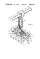
- FIG. 7is a perspective view showing the structure and operation of the transfer head of the apparatus of FIG. 1;
- FIG. 8is a sectional view illustrating the vacuum ports of the transfer head of FIG. 7.
- FIGS. 9 and 10are illustrations of the operation of the vacuum port of FIG. 8.
- the system 10includes a product infeed conveyor 12 which functions to deliver bakery products to a transfer zone 14.
- a basket/tray infeed conveyor 16functions to deliver bakery product receiving baskets and/or trays to the transfer zone 14.
- a conveyor 18functions to remove filled baskets or trays from the transfer zone 14 for transfer to remote locations.
- the product infeed conveyor 12comprises an endless belt 22 supported on a frame 24 for movement around a predetermined course.
- the belt 22receives bakery products previously wrapped in plastic film from the wrapping apparatus (not shown) and functions to deliver the film wrapped bakery products to the transfer zone 14.
- the frame 24is supported on a plurality of uprights 26 each including a conventional positioning mechanism 28 which may be utilized to properly position the upper surface of the endless belt 22 of the conveyor 12 relative to the remaining components of the pattern former/loader system 10.
- a fixed guide 32is secured at one side of the upper course of the belt 22 of the conveyor 12.
- a movable guide 34is located at the opposite side.
- the movable guide 34includes guide member 36 which extend through bushings 38 to maintain alignment of the movable guide 34.
- a lead screw 40is threadedly engaged with an internally threaded member 42 for actuation by a handle 44 to vary the positioning of the movable guide 34. In this manner products carried by the endless belt 22 are uniformly positioned upon arrival at the transfer zone 14.
- the tray/basket infeed conveyor 16comprises an endless belt 46 supported by a frame 48 for movement around a predetermined course.
- the frame 48is in turn supported by a plurality of supports 50.
- the supports 50also support a frame 52 which supports an endless belt 54 comprising the conveyor 18.
- the function of the infeed conveyor 16is to receive empty bakery product receiving baskets and/or trays from a remote location and to deliver the basket and/or trays to a transfer conveyor 56.
- the conveyor 56functions to locate individual baskets and/or trays in the transfer zone 14.
- bakery products received on the conveyor 12are transferred from the conveyor 12 and located into each basket and/or tray received from the infeed conveyor 16 in accordance with a predetermined pattern. After each basket and/or tray is filled it is delivered by the transfer conveyor 56 to the conveyor 18 for removal to a remote location.
- the transfer conveyor 56comprises an endless belt 58 supported by a frame 60 for movement around a predetermined course.
- the frame 60is in turn supported by a frame 62 for pivotal movement between the positions shown in full line and in phantom line in FIG. 2 under the action of a fluid powered cyliner 64.
- the belt 58is driven by a motor 68 which is drivingly connected to the belt 58 through a drive mechanism 70.
- the pattern former/loader system 10includes a frame 80 including a plurality of uprights 82 which comprise the main structural components of the system. Longitudinally extending members 84 and tranversely extending members 86 define the lower portion of the frame 80. The upper portion of the frame 80 comprises longitudinally extending members 88 and transversely extending members 90.
- the frame 80supports a pair of longitudinally extending guideways 92. As is best shown in FIGS. 2 and 4, a pair of carriages 94 are supported by the first guideways 92 for movement therealong in the longitudinal direction. A belt 96 is constrained around a pair of rollers 98 and 100 for movement around a longitudinally extending course. A servo motor 102 is drivingly connected to one of the rollers 98 through a drive mechanism 104. Thus, the pair of carriages 94 are positionable along a first horizontal axis by the servo motor 102 operating through the drive mechanism 104, the rollers 98, and the belt 96.
- the pair of carriages 94support a second, transversely extending guideway 110.
- a second carriage 112is supported by the second guideway 110 for movement along a second horizontal axis extending perpendicularly to the first horizontal axis.
- a pair of rollers 114 and 116are mounted at opposite ends of the second guideway 110.
- a belt 118is constrained around the rollers 114 and 116 for movement around a transversely extending course which is parallel to the second guideway 110.
- the belt 118is connected to the second carriage 112.
- a servo motor 120is drivingly connected to a splined shaft 122 through a drive mechanism 124.
- the splined shaft 122is in turn drivingly connected to the rollers 114 through a rolling nut 126.
- the servo motor 120operates through the drive mechanism 124, the splined shaft 122, the roller nut 126, one of the rollers 114 and the belt 118 to position the second carriage 112 along the second guideway 110 regardless of the positioning of the carriage 94 along the guideways 92 under the action of the servo motor 102.
- the guideways 92 and the carriages 94may be of the type manufactured by Roller Slide Company of Solon, Ohio and identified by that company as model number 50 L 60.
- the guideway 110 and the carriage 112may be of the type manufactured by Roller Slide Company under model number 50 LW 32.
- the servo motors 102 and 120may be of the type manufactured by Inland Company of Radford, Va. under model numbers TTR 2953 and TTR 2952, respectively.
- the splined shaft 122 and the rolling nut 126may be of the type manufactured by Beaver Precision Products, Inc. of Troy, Mich. and identified by that company as model number CS-1500.
- An actuator 130is carried by the second carriage 112 and in turn supports a transfer head 132.
- the transfer head 132Upon actuation of the servo motors 102 and 120, the transfer head 132 is positionable at any desired location within a predetermined range of movement as determined by the limits of travel of the carriages 94 and 112 along the guideways 92 and 110, respectively.
- the product infeed conveyor 12functions to position bakery products at a location of the range of movement within the transfer head 132.
- the basket/tray infeed conveyor 16 and the transfer conveyor 56function to position bakery product receiving baskets and/or trays at a location within the range of motion of the transfer head 132.
- the function of the transfer head 132is to receive bakery products from the product infeed conveyor 132 and to load the products into trays or baskets received from the infeed conveyor 16 in accordance with a predetermined pattern.
- the actuator 130is preferably of the type manufactured by PHD, Inc. of Fort Wayne, Ind., and identified by that company as model number 6000.
- the actuator 130has a shaft 134 extending downwardly from the lower end thereof.
- the transfer head 132includes a bracket 136 which is threadedly engaged with the shaft 134 and the plate 138 which is secured to the bracket 136 by means of fasteners 140.
- the actuator 130performs two functions in the operation of the pattern former/loader system 10. First, the actuator 130 functions to position the transfer head 132 in any of four rotative positions spaced 90° apart.
- the actuator 130defines a vertical axis and functions to rotate the transfer head in either direction about the vertical axis and thereby positioning products carried by the transfer head 132 in any desired orientation with the products extending transversely or longitudinally.
- the actuator 130also functions to position the transfer head 132 in either of two positions vertically, that is, in either of two positions along the vertical axis, including a lower product receiving and discharging system and an upper product transporting position.
- the transfer head 132comprises a plurality of vacuum ports 142. Each vacuum port 142 is connected in communication with a transducer 144, which may be of the type manufactured by Air-Vac, Inc. of Milford, Conn. under model number AVD 260 M. A hose 146 extends from a source of compressed air to each transducer 144. The transducer 144 operates on the Venturi principle, whereby each transducer 144 functions as a vacuum source to its associated vacuum port 142. The transducers 144 are adapted for individual actuation, thereby facilitating the receipt by and/or the discharge from the vacuum heads of individual bakery products or groups of products in order to form a desired pattern in the loading of bakery product receiving baskets and/or trays.
- the transfer head 132further comprises a pair of opposed loaf tucking apparatus 150.
- Each loaf tucking apparatus 150includes a bell crank 152 comprising a first arm 154 which is pivotally connected to a bracket 156 secured to the plate 138.
- An upwardly extending arm 158is pivotally connected to a clevis 160 which is secured to a fluid powered cylinder 162 which in turn is secured to the plate 138 by means of bracket 164.
- a plurality of fingers 166project downwardly from the bell crank 152.
- the function of the loaf tucking apparatus 150 at each end of the transfer heads 132is to confine bakery products supported by the transfer head 132 to a predetermined dimension, thereby facilitating the loading of the products into bakery product receiving baskets and/or trays.
- the fluid powered cylinders 162are intially actuated to pivot the fingers 166 upwardly. In this manner receipt of bakery products from the product infeed conveyor 12 is facilitated. After the bakery products have been received and lifted to the product transporting position by operation of the actuator 130, the fluid powered cylinders 162 are actuated to pivot the fingers 166 into the positions shown in FIG. 7.
- any tendency of the bakery products to project outwardly beyond a predetermined lateral dimensionis eliminated, thereby facilitating the positioning of bakery products within product receiving baskets and/or trays.
- the fingers 166are retained in the positions illustrated in FIG. 7 until the loading of the bakery products into the baskets and/or trays has been completed.
- Each vacuum port 142comprises a vacuum cup 170 formed from a relatively resilient material.
- the vacuum cup 170is formed from food grade neoprene rubber, Shore A 40 durometer.
- the cup 170comprises a hollow cylinder which is connected at one end to a tubular fitting 172 that is in turn connected to the transducer 144 associated with the particular vacuum port 142.
- the transducer 144serves as a vacuum source for the vacuum port 142, whereby vacuum is established within the interior of the vacuum cup 170 through the fitting 172.
- a vacuum cup insert 174is positioned within the vacuum cup 170.
- the vacuum cup insert 174is formed from a relatively rigid material and thereby serves to retain the shape of the relatively resilient vacuum cup 170.
- the vacuum cup insert 170has a plurality of small diameter apertures 176 formed therein.
- the vacuum cup 170had an inside diameter of about 2.25 inches.
- the vacuum inserthad a total of 24 apertures 176 formed therethrough.
- the apertures 176each had a diameter of about 0.090 inches, and were arranged at equally spaced intervals about a circle having a diameter of about 1.990 inches.
- the cross sectional area of the vacuum cup 170is approximately 4 inches
- the total cross sectional area of all of the apertures 176 formed through the vacuum cup insert 174is approximately 0.15 inches.
- the vacuum cup insert 174therefore serves to substantially restrict the flow of air through the vacuum cup 170 in response to the vacuum established therein through the fitting 172.
- An important feature of the vacuum port 142comprises the product engaging end 178 of the vacuum cup 170.
- the product engaging end 178is characterized by an annular surface 180 which extends angularly upwardly and inwardly toward the axis of the vacuum cup 170 at a angle of about 30°.
- the surface 180terminates at the upper end thereof in an outwardly turned annular lip 182. It has been found that the combination of the angularly upwardly and inwardly extending annular surface 180 and the outwardly turned annular lip 182 is highly important to the successful operation of the vacuum port 142.
- FIGS. 9 and 10there is shown a loaf of bread L which is wrapped in the usual plastic film F.
- the vacuum port 142engages the loaf of bread L which is supported on an underlying surface.
- the plastic film Fmoves upwardly into the interior thereof and initially comes into engagement both with the angularly upwardly inclined annular surface 180 and with the interior of the outwardly turned annular lip 182.
- the use of the angularly upwardly and inwardly extending surface 180is important at this point in preventing tearing or other damage to the plastic film F.
- the plastic film Fpulls away from the angularly upwardly and inwardly extending surface 180 but remains engaged with the interior surface of the outwardly turned lip 182. In this manner the vacuum port 142 lifts the loaf of bread L or other bakery product without damaging the plastic film F which serves to wrap and protect the bakery product.
- the pattern former/loader system 10further includes a control unit 190.
- the control unit 190includes a programmable controller of the type manufactured by Westinghouse of Madison Heights, Wis. under model PC700 and an interactive display of the type manufactured by Industrial Electronics Engineers of Van Nuys, Calif. under model number 4201-02.
- the interactive displayis utilized to direct instructions to the programmable controller regarding desired movements of the transfer head 132.
- the programmable controllerin turn controls the operation of Westinghouse model number NL761 servo control modules which serve to store the instructions received by the programmable controller from the interactive display.
- the programmable controller within the control unit 190also receives instructions through the interactive display with respect to the operation of the vacuum ports and the operation of the actuator 130.
- the received instructions with respect to transfer head positioning, vacuum port operation and actuator operationare stored in the programmable controller so that after a required sequence has been fed to the programmable controller, the sequence can be carried out on a repetitive basis.
- the control unit 190further includes an Inland model number SBD2-10,20 servo amplifier which supplies operating power to the servo motors 102 and 120.
- the drive mechanisms 104 and 124 associated with the servo motors 102 and 120, respectively,include resolvers which provide an output indicative of the location of the transfer head 132 in the longitudinal and transverse directions. In this manner the transfer head is precisely located as required for each step in a particular loading operation.
- the actuator 130is operated as required to raise and lower the transfer head 130 and to rotate the transfer head to effect positioning operations, and the vacuum ports 142 are selectively actuated and deactuated to receive and discharge bakery products.
- the operating sequenceis continuously repeated thereby transferring bakery products from the infeed conveyor 12 to the product receiving baskets and/or trays that are positioned by the conveyor 16 and the conveyor 56.
Landscapes
- Engineering & Computer Science (AREA)
- Mechanical Engineering (AREA)
- Bakery Products And Manufacturing Methods Therefor (AREA)
- Specific Conveyance Elements (AREA)
- Manufacturing And Processing Devices For Dough (AREA)
Abstract
Description
Claims (8)
Priority Applications (3)
| Application Number | Priority Date | Filing Date | Title |
|---|---|---|---|
| US06/593,089US4699559A (en) | 1984-03-26 | 1984-03-26 | Pattern former/loader system for bakery products |
| GB08507649AGB2156762B (en) | 1984-03-26 | 1985-03-25 | Transfer device for bakery products |
| CA000477371ACA1257302A (en) | 1984-03-26 | 1985-03-25 | Pattern former/loader system for bakery products |
Applications Claiming Priority (1)
| Application Number | Priority Date | Filing Date | Title |
|---|---|---|---|
| US06/593,089US4699559A (en) | 1984-03-26 | 1984-03-26 | Pattern former/loader system for bakery products |
Publications (1)
| Publication Number | Publication Date |
|---|---|
| US4699559Atrue US4699559A (en) | 1987-10-13 |
Family
ID=24373336
Family Applications (1)
| Application Number | Title | Priority Date | Filing Date |
|---|---|---|---|
| US06/593,089Expired - Fee RelatedUS4699559A (en) | 1984-03-26 | 1984-03-26 | Pattern former/loader system for bakery products |
Country Status (3)
| Country | Link |
|---|---|
| US (1) | US4699559A (en) |
| CA (1) | CA1257302A (en) |
| GB (1) | GB2156762B (en) |
Cited By (21)
| Publication number | Priority date | Publication date | Assignee | Title |
|---|---|---|---|---|
| US4911598A (en)* | 1986-04-28 | 1990-03-27 | International Business Machines Corporation | Robotic assembly apparatus with robot tool for placing a plurality of component parts on a workpiece |
| US5073079A (en)* | 1990-05-17 | 1991-12-17 | Intelmatec Corporation | Modular loading-unloading system for integrated circuits or the like |
| US5135349A (en)* | 1990-05-17 | 1992-08-04 | Cybeq Systems, Inc. | Robotic handling system |
| US20050218677A1 (en)* | 2003-01-21 | 2005-10-06 | Embrex, Inc. | Vacuum assisted methods of removing eggs |
| US20060042194A1 (en)* | 1999-10-14 | 2006-03-02 | Lucido John M | Pattern former for wrapped bakery products and bakery tray loading system |
| DE102005049882B3 (en)* | 2005-10-17 | 2007-02-01 | Uhlmann Pac-Systeme Gmbh & Co. Kg. | Guiding and depositing device for small articles has filling plates movable from filling position to depositing position by pushing device |
| US20070261368A1 (en)* | 2006-05-11 | 2007-11-15 | Uhlmann Pac-Systeme Gmbh & Co. Kg | Conveyor for feeding small objects to a blister-film loader |
| US20080178748A1 (en)* | 2002-09-10 | 2008-07-31 | Reading Bakery Systems | Apparatus and Method for Movement and Rotation of Dough Sheets to Produce a Bakery Products |
| US20090249750A1 (en)* | 2008-04-03 | 2009-10-08 | Arm Automation, Inc. | Automated collector device and methods |
| US20100025905A1 (en)* | 2008-07-30 | 2010-02-04 | J. Schmalz Gmbh | Pneumatically actuated area vacuum gripper |
| US20100269453A1 (en)* | 2008-06-13 | 2010-10-28 | Takai Tofu & Soymilk Equipment Co. | Automatic tofu-packing apparatus |
| US20120317934A1 (en)* | 2010-12-28 | 2012-12-20 | Takai Tofu & Soymilk Equipment Co. | Packing device of tofu |
| CN103723514A (en)* | 2013-11-21 | 2014-04-16 | 格力电器(石家庄)有限公司 | Automatic feeding device for bottom support of indoor unit of air conditioner |
| EP1954995A4 (en)* | 2005-11-28 | 2015-10-21 | Optimar Giske As | DRAINING DEVICE FOR VERTICAL FREEZERS |
| CN105692133A (en)* | 2016-03-29 | 2016-06-22 | 山东小鸭精工机械有限公司 | Feeding equipment of board rim production line |
| CN107840074A (en)* | 2017-10-26 | 2018-03-27 | 姚巧宁 | A kind of machine driving feed device |
| CN108100561A (en)* | 2017-12-11 | 2018-06-01 | 淮南师范学院 | A kind of machinery material drive apparatus |
| WO2020249172A1 (en)* | 2019-06-11 | 2020-12-17 | Intech International A/S | Freezing facility |
| US20210387818A1 (en)* | 2020-06-16 | 2021-12-16 | Denso Wave Incorporated | Method and device for controlling workpiece suction-gripping actions of robot |
| WO2023137524A1 (en)* | 2022-01-20 | 2023-07-27 | Matthew Ian Angilley | Automated punnets handling assembly |
| CN116946468A (en)* | 2023-08-26 | 2023-10-27 | 中山市越海电器有限公司 | Lifting equipment for wine cabinet packaging |
Families Citing this family (6)
| Publication number | Priority date | Publication date | Assignee | Title |
|---|---|---|---|---|
| SE461389B (en)* | 1986-07-10 | 1990-02-12 | Volvo Ab | PROCEDURE AND DEVICE FOR THE TRANSFER OF GOODS |
| FR2627761A1 (en)* | 1988-02-26 | 1989-09-01 | Joulin Aero Distribution | Flat plate transfer transformer - has scissors jack carrying chassis with suction plate and plate alignment stops |
| DE4025846C1 (en)* | 1990-08-16 | 1991-12-12 | Fraunhofer-Gesellschaft Zur Foerderung Der Angewandten Forschung Ev, 8000 Muenchen, De | Open folding carton vacuum lifter - has several suction grippers, with at least on exerting variable, inwards force onto lid flap(s) |
| FR2700664B1 (en)* | 1993-01-28 | 1995-04-21 | Acr | Pot handling machine especially for agricultural or horticultural operations. |
| DE4425127A1 (en)* | 1994-07-15 | 1996-01-18 | Dreier Systemtechnik Ag | Storage system for order picking |
| FR2929257B1 (en)* | 2008-03-28 | 2010-04-23 | Ballina Freres De | PNEUMATIC PREHENSER AND GRIPPING DEVICE HAVING A PLURALITY OF SUCH PREHENSEURS |
Citations (19)
| Publication number | Priority date | Publication date | Assignee | Title |
|---|---|---|---|---|
| US2716497A (en)* | 1953-12-09 | 1955-08-30 | Ballantine & Sons P | Apparatus for handling materials |
| US2827178A (en)* | 1955-05-05 | 1958-03-18 | Ballantine & Sons P | Suction grasping apparatus |
| US3318068A (en)* | 1963-07-26 | 1967-05-09 | Voullaire Izak Johannes | Packing of fruit |
| US3368324A (en)* | 1963-12-09 | 1968-02-13 | Lockwood Mfg Company | Packaging apparatus |
| US3542214A (en)* | 1968-12-23 | 1970-11-24 | Dino Dicarlo | Stacking and transmission device for packages |
| US3648853A (en)* | 1970-04-03 | 1972-03-14 | Erie Eng Co | Vacuum work pick-up attachment for work device |
| US3697112A (en)* | 1971-04-15 | 1972-10-10 | Eaton Yale & Towne | Vacuum pick up head |
| US3698755A (en)* | 1971-04-29 | 1972-10-17 | Diebold Inc | Vacuum head magnetic valve construction for pallet loader |
| US3757966A (en)* | 1971-03-12 | 1973-09-11 | J & J Manuf Co | Palletizing apparatus |
| US3836018A (en)* | 1971-12-13 | 1974-09-17 | Alvey Inc | Discrete article palletizing and depalletizing apparatus |
| US3884363A (en)* | 1973-09-13 | 1975-05-20 | Bendix Corp | Programmable universal transfer device |
| US4184799A (en)* | 1977-01-08 | 1980-01-22 | Laeis-Werke Ag | Setting and stacking arrangement |
| US4191003A (en)* | 1978-04-19 | 1980-03-04 | Talarico Lawrence J | Tray loader |
| US4242025A (en)* | 1977-07-08 | 1980-12-30 | Thibault Jacques G | Palettizing-depalettizing apparatus |
| US4246740A (en)* | 1977-10-27 | 1981-01-27 | Sapal Societe Anonyme Des Plieuses Automatiques | Method and apparatus for filling a box with objects |
| US4252497A (en)* | 1977-08-22 | 1981-02-24 | Heico Inc. | Article handling system |
| US4316693A (en)* | 1979-03-05 | 1982-02-23 | Columbia Machine, Inc. | Variable array can palletizer |
| US4383788A (en)* | 1980-01-28 | 1983-05-17 | Wamac-Idab Ab | Arrangement for a machine particularly intended for handling loose signature packs |
| US4419039A (en)* | 1981-03-04 | 1983-12-06 | Bengtsson Bengt A | Apparatus for loading objects |
Family Cites Families (2)
| Publication number | Priority date | Publication date | Assignee | Title |
|---|---|---|---|---|
| GB1052051A (en)* | ||||
| US3374600A (en)* | 1964-12-15 | 1968-03-26 | American Mach & Foundry | Method and apparatus for packaging |
- 1984
- 1984-03-26USUS06/593,089patent/US4699559A/ennot_activeExpired - Fee Related
- 1985
- 1985-03-25CACA000477371Apatent/CA1257302A/ennot_activeExpired
- 1985-03-25GBGB08507649Apatent/GB2156762B/ennot_activeExpired
Patent Citations (19)
| Publication number | Priority date | Publication date | Assignee | Title |
|---|---|---|---|---|
| US2716497A (en)* | 1953-12-09 | 1955-08-30 | Ballantine & Sons P | Apparatus for handling materials |
| US2827178A (en)* | 1955-05-05 | 1958-03-18 | Ballantine & Sons P | Suction grasping apparatus |
| US3318068A (en)* | 1963-07-26 | 1967-05-09 | Voullaire Izak Johannes | Packing of fruit |
| US3368324A (en)* | 1963-12-09 | 1968-02-13 | Lockwood Mfg Company | Packaging apparatus |
| US3542214A (en)* | 1968-12-23 | 1970-11-24 | Dino Dicarlo | Stacking and transmission device for packages |
| US3648853A (en)* | 1970-04-03 | 1972-03-14 | Erie Eng Co | Vacuum work pick-up attachment for work device |
| US3757966A (en)* | 1971-03-12 | 1973-09-11 | J & J Manuf Co | Palletizing apparatus |
| US3697112A (en)* | 1971-04-15 | 1972-10-10 | Eaton Yale & Towne | Vacuum pick up head |
| US3698755A (en)* | 1971-04-29 | 1972-10-17 | Diebold Inc | Vacuum head magnetic valve construction for pallet loader |
| US3836018A (en)* | 1971-12-13 | 1974-09-17 | Alvey Inc | Discrete article palletizing and depalletizing apparatus |
| US3884363A (en)* | 1973-09-13 | 1975-05-20 | Bendix Corp | Programmable universal transfer device |
| US4184799A (en)* | 1977-01-08 | 1980-01-22 | Laeis-Werke Ag | Setting and stacking arrangement |
| US4242025A (en)* | 1977-07-08 | 1980-12-30 | Thibault Jacques G | Palettizing-depalettizing apparatus |
| US4252497A (en)* | 1977-08-22 | 1981-02-24 | Heico Inc. | Article handling system |
| US4246740A (en)* | 1977-10-27 | 1981-01-27 | Sapal Societe Anonyme Des Plieuses Automatiques | Method and apparatus for filling a box with objects |
| US4191003A (en)* | 1978-04-19 | 1980-03-04 | Talarico Lawrence J | Tray loader |
| US4316693A (en)* | 1979-03-05 | 1982-02-23 | Columbia Machine, Inc. | Variable array can palletizer |
| US4383788A (en)* | 1980-01-28 | 1983-05-17 | Wamac-Idab Ab | Arrangement for a machine particularly intended for handling loose signature packs |
| US4419039A (en)* | 1981-03-04 | 1983-12-06 | Bengtsson Bengt A | Apparatus for loading objects |
Cited By (38)
| Publication number | Priority date | Publication date | Assignee | Title |
|---|---|---|---|---|
| US4911598A (en)* | 1986-04-28 | 1990-03-27 | International Business Machines Corporation | Robotic assembly apparatus with robot tool for placing a plurality of component parts on a workpiece |
| US5073079A (en)* | 1990-05-17 | 1991-12-17 | Intelmatec Corporation | Modular loading-unloading system for integrated circuits or the like |
| US5135349A (en)* | 1990-05-17 | 1992-08-04 | Cybeq Systems, Inc. | Robotic handling system |
| US7191578B2 (en)* | 1999-10-14 | 2007-03-20 | Stewart Systems, Inc. | Pattern former for wrapped bakery products and bakery tray loading system |
| US20060042194A1 (en)* | 1999-10-14 | 2006-03-02 | Lucido John M | Pattern former for wrapped bakery products and bakery tray loading system |
| US20080178748A1 (en)* | 2002-09-10 | 2008-07-31 | Reading Bakery Systems | Apparatus and Method for Movement and Rotation of Dough Sheets to Produce a Bakery Products |
| US20050218677A1 (en)* | 2003-01-21 | 2005-10-06 | Embrex, Inc. | Vacuum assisted methods of removing eggs |
| US7207609B2 (en)* | 2003-01-21 | 2007-04-24 | Embrex, Inc. | Vacuum assisted methods of removing eggs |
| US20070084141A1 (en)* | 2005-10-17 | 2007-04-19 | Uhlmann Pac-Systeme Gmbh & Co. Kg | Apparatus for loading small objects into blisters of a foil web |
| US7328557B2 (en) | 2005-10-17 | 2008-02-12 | Uhlmann Pac-Systeme Gmbh & Co. Kg | Apparatus for loading small objects into blisters of a foil web |
| DE102005049882B3 (en)* | 2005-10-17 | 2007-02-01 | Uhlmann Pac-Systeme Gmbh & Co. Kg. | Guiding and depositing device for small articles has filling plates movable from filling position to depositing position by pushing device |
| EP1954995A4 (en)* | 2005-11-28 | 2015-10-21 | Optimar Giske As | DRAINING DEVICE FOR VERTICAL FREEZERS |
| US20070261368A1 (en)* | 2006-05-11 | 2007-11-15 | Uhlmann Pac-Systeme Gmbh & Co. Kg | Conveyor for feeding small objects to a blister-film loader |
| DE102006022262B3 (en)* | 2006-05-11 | 2007-11-29 | Uhlmann Pac-Systeme Gmbh & Co Kg | Device for the ordered feeding and depositing small parts to be packed in the wells of a film web |
| US7565781B2 (en) | 2006-05-11 | 2009-07-28 | Uhlmann Pac-Systeme Gmbh & Co. Kg | Conveyor for feeding small objects to a blister-film loader |
| US20110056176A1 (en)* | 2008-04-03 | 2011-03-10 | Arm Automation, Inc. | Automated collector device and methods |
| US7856797B2 (en) | 2008-04-03 | 2010-12-28 | Arm Automation, Inc. | Automated collector device and methods |
| US20090249750A1 (en)* | 2008-04-03 | 2009-10-08 | Arm Automation, Inc. | Automated collector device and methods |
| US20100269453A1 (en)* | 2008-06-13 | 2010-10-28 | Takai Tofu & Soymilk Equipment Co. | Automatic tofu-packing apparatus |
| US20100025905A1 (en)* | 2008-07-30 | 2010-02-04 | J. Schmalz Gmbh | Pneumatically actuated area vacuum gripper |
| US8267386B2 (en)* | 2008-07-30 | 2012-09-18 | J. Schmalz Gmbh | Pneumatically actuated area vacuum gripper |
| US20120317934A1 (en)* | 2010-12-28 | 2012-12-20 | Takai Tofu & Soymilk Equipment Co. | Packing device of tofu |
| US9352866B2 (en)* | 2010-12-28 | 2016-05-31 | Takai Tofu & Soymilk Equipment Co. | Packing device of tofu |
| CN103723514A (en)* | 2013-11-21 | 2014-04-16 | 格力电器(石家庄)有限公司 | Automatic feeding device for bottom support of indoor unit of air conditioner |
| CN105692133A (en)* | 2016-03-29 | 2016-06-22 | 山东小鸭精工机械有限公司 | Feeding equipment of board rim production line |
| CN105692133B (en)* | 2016-03-29 | 2017-09-01 | 山东小鸭精工机械有限公司 | A kind of plate wheel rim production line charging equipment |
| CN107840074A (en)* | 2017-10-26 | 2018-03-27 | 姚巧宁 | A kind of machine driving feed device |
| CN108100561A (en)* | 2017-12-11 | 2018-06-01 | 淮南师范学院 | A kind of machinery material drive apparatus |
| WO2020249172A1 (en)* | 2019-06-11 | 2020-12-17 | Intech International A/S | Freezing facility |
| CN114207368A (en)* | 2019-06-11 | 2022-03-18 | 英特克国际有限公司 | Refrigeration facility |
| CN114207368B (en)* | 2019-06-11 | 2024-04-05 | 嘉烁海鲜有限公司 | Refrigeration facility |
| US20210387818A1 (en)* | 2020-06-16 | 2021-12-16 | Denso Wave Incorporated | Method and device for controlling workpiece suction-gripping actions of robot |
| JP2021194745A (en)* | 2020-06-16 | 2021-12-27 | 株式会社デンソーウェーブ | Robot control method, suction holding device |
| US11964828B2 (en)* | 2020-06-16 | 2024-04-23 | Denso Wave Incorporated | Method and device for controlling workpiece suction-gripping actions of robot |
| WO2023137524A1 (en)* | 2022-01-20 | 2023-07-27 | Matthew Ian Angilley | Automated punnets handling assembly |
| AU2023209797B2 (en)* | 2022-01-20 | 2024-05-02 | Matthew Ian Angilley | Automated punnets handling assembly |
| CN116946468A (en)* | 2023-08-26 | 2023-10-27 | 中山市越海电器有限公司 | Lifting equipment for wine cabinet packaging |
| CN116946468B (en)* | 2023-08-26 | 2024-03-26 | 中山市越海电器有限公司 | Lifting equipment for wine cabinet packaging |
Also Published As
| Publication number | Publication date |
|---|---|
| GB2156762A (en) | 1985-10-16 |
| CA1257302A (en) | 1989-07-11 |
| GB2156762B (en) | 1987-10-21 |
| GB8507649D0 (en) | 1985-05-01 |
Similar Documents
| Publication | Publication Date | Title |
|---|---|---|
| US4699559A (en) | Pattern former/loader system for bakery products | |
| US4936203A (en) | Apparatus for shaping and arraying spheroidal bodies of food materials | |
| US6082080A (en) | Device for mechanically grasping and palletizing rectangular objects | |
| US6234745B1 (en) | Container destacking and transfer apparatus | |
| EP0328170A2 (en) | Shaping device | |
| US5383760A (en) | Apparatus and method for container pattern-forming and palletizing | |
| EP2289826B1 (en) | Manually controlled depalletizing machine | |
| US8528955B2 (en) | Robot end effector with cable management | |
| US11780718B2 (en) | Accessory modular device for AGV | |
| US3292341A (en) | Orienting and packing apparatus | |
| JPH08505595A (en) | Palletizer | |
| US5765337A (en) | Apparatus and method for stacking and boxing stackable articles | |
| US5661949A (en) | Automatic packing device for the filling of containers with superimposed layers of products | |
| US5935629A (en) | Apparatus and method for cross-scoring a dough loaf | |
| US4598534A (en) | Apparatus and method for conveying, weighing and roll wrapping articles | |
| US4974391A (en) | Automatic package loading system for bakery goods and the like | |
| CN112811195A (en) | Whole-layer unstacker | |
| CA1236050A (en) | Code sorting and handling system for beaded tires | |
| JPH0418210A (en) | Device for packing container with article in predetermined distributing manner | |
| US5415520A (en) | Apparatus for loading drums on pallets | |
| EP4116241B1 (en) | Compact depalletizing machine | |
| US5599268A (en) | Belt driven linear transport apparatus for packaging machine | |
| EP0017489A1 (en) | Automatic apparatus for handling ceramic ware | |
| US6461100B1 (en) | Method and apparatus for removing tire treads from storage device | |
| US3968887A (en) | Article pick-up and transfer apparatus |
Legal Events
| Date | Code | Title | Description |
|---|---|---|---|
| AS | Assignment | Owner name:STEWART SYSTEMS, INC., 808 STEWART AVENUE, PLANO, Free format text:ASSIGNMENT OF ASSIGNORS INTEREST.;ASSIGNORS:BIBBO, KENNETH L.;PODSIAD, PAUL;REEL/FRAME:004244/0731 Effective date:19840323 | |
| AS | Assignment | Owner name:REPUBLICBANK DALLAS, N.A., PACIFIC AND ERVAY ST., Free format text:ASSIGNMENT OF ASSIGNORS INTEREST.;ASSIGNOR:STEWART SYSTEMS, INC;REEL/FRAME:004402/0240 Effective date:19850308 | |
| AS | Assignment | Owner name:NCNB TEXAS NATIONAL BANK, A NATIONAL BANKING ASSOC Free format text:ASSIGNMENT OF ASSIGNORS INTEREST.;ASSIGNOR:NCNB TEXAS NATIONAL BANK;REEL/FRAME:005069/0538 Effective date:19890208 Owner name:FIRST CITY NATIONAL BANK OF HOUSTON, TEXAS Free format text:SECURITY INTEREST;ASSIGNOR:STEWART SYSTEMS, INC.;REEL/FRAME:005069/0511 Effective date:19890208 Owner name:FIRST CITY NATIONAL BANK OF HOUSTON, A NATIONAL BA Free format text:ASSIGNMENT OF ASSIGNORS INTEREST.;ASSIGNOR:NCNB TEXAS NATIONAL BANK;REEL/FRAME:005069/0538 Effective date:19890208 | |
| AS | Assignment | Owner name:STEWART SYSTEMS, INC. Free format text:RELEASED BY SECURED PARTY;ASSIGNOR:FIRST CITY, TEXAS-HOUSTON, N.A., FKA FIRST CITY NATIONAL BANK OF HOUSTON;REEL/FRAME:005521/0421 Effective date:19900515 Owner name:STEWART SYSTEMS, INC. Free format text:RELEASED BY SECURED PARTY;ASSIGNOR:FIRST CITY, TEXAS-HOUSTON, N.A. FKA FIRST CITY NATIONAL BANK OF HOUSTON;REEL/FRAME:005521/0393 Effective date:19900515 | |
| REMI | Maintenance fee reminder mailed | ||
| LAPS | Lapse for failure to pay maintenance fees | ||
| FP | Lapsed due to failure to pay maintenance fee | Effective date:19911013 | |
| AS | Assignment | Owner name:STEWART SYSTEMS, INC., A CORP. OF DE Free format text:MERGER;ASSIGNORS:STEWART SYSTEMS, INC., A CORP. OF TX (MERGED INTO);SASIB BAKERY EQUIPMENT, INC., A DE CORP. (CHANGED INTO);REEL/FRAME:006011/0042 Effective date:19901218 | |
| STCH | Information on status: patent discontinuation | Free format text:PATENT EXPIRED DUE TO NONPAYMENT OF MAINTENANCE FEES UNDER 37 CFR 1.362 |