US4699270A - Modular packaging system - Google Patents
Modular packaging systemDownload PDFInfo
- Publication number
- US4699270A US4699270AUS06/774,036US77403685AUS4699270AUS 4699270 AUS4699270 AUS 4699270AUS 77403685 AUS77403685 AUS 77403685AUS 4699270 AUS4699270 AUS 4699270A
- Authority
- US
- United States
- Prior art keywords
- module
- modules
- side wall
- flange
- side walls
- Prior art date
- Legal status (The legal status is an assumption and is not a legal conclusion. Google has not performed a legal analysis and makes no representation as to the accuracy of the status listed.)
- Expired - Fee Related
Links
- 238000004806packaging method and processMethods0.000titleclaimsabstractdescription41
- 230000002093peripheral effectEffects0.000claimsdescription6
- 238000009432framingMethods0.000description4
- 230000000712assemblyEffects0.000description3
- 238000000429assemblyMethods0.000description3
- 238000010276constructionMethods0.000description3
- 230000000717retained effectEffects0.000description2
- 238000009423ventilationMethods0.000description2
- 230000000007visual effectEffects0.000description2
- VVQNEPGJFQJSBK-UHFFFAOYSA-NMethyl methacrylateChemical compoundCOC(=O)C(C)=CVVQNEPGJFQJSBK-UHFFFAOYSA-N0.000description1
- 229920005372Plexiglas®Polymers0.000description1
- XAGFODPZIPBFFR-UHFFFAOYSA-NaluminiumChemical compound[Al]XAGFODPZIPBFFR-UHFFFAOYSA-N0.000description1
- 229910052782aluminiumInorganic materials0.000description1
- DMFGNRRURHSENX-UHFFFAOYSA-Nberyllium copperChemical compound[Be].[Cu]DMFGNRRURHSENX-UHFFFAOYSA-N0.000description1
- 230000009977dual effectEffects0.000description1
- 230000000694effectsEffects0.000description1
- 238000013023gasketingMethods0.000description1
- 238000003754machiningMethods0.000description1
- 238000000034methodMethods0.000description1
- 238000012986modificationMethods0.000description1
- 230000004048modificationEffects0.000description1
Images


Classifications
- H—ELECTRICITY
- H05—ELECTRIC TECHNIQUES NOT OTHERWISE PROVIDED FOR
- H05K—PRINTED CIRCUITS; CASINGS OR CONSTRUCTIONAL DETAILS OF ELECTRIC APPARATUS; MANUFACTURE OF ASSEMBLAGES OF ELECTRICAL COMPONENTS
- H05K5/00—Casings, cabinets or drawers for electric apparatus
- H05K5/30—Side-by-side or stacked arrangements
- H—ELECTRICITY
- H05—ELECTRIC TECHNIQUES NOT OTHERWISE PROVIDED FOR
- H05K—PRINTED CIRCUITS; CASINGS OR CONSTRUCTIONAL DETAILS OF ELECTRIC APPARATUS; MANUFACTURE OF ASSEMBLAGES OF ELECTRICAL COMPONENTS
- H05K7/00—Constructional details common to different types of electric apparatus
- H05K7/18—Construction of rack or frame
Definitions
- the present inventionrelates to the mounting and storage of electrical components, such as printed circuit boards and the like, and more particularly relates to a modular packaging system for such components.
- a vertical cabinetincluding a frame and vertical mounting rails attached along the front sides of the frame; and second, subframes or subracks holding electrical components and adapted to slide within the main frame.
- the subframesuch as a "card cage” occupies a significant amount of space along the interior sides of the main frame, space which therefore cannot be used for the storage of the electrical components themselves.
- a standard card cage designed to fit into a standard 19 inch vertical cabinethas only 16.8 inches of usable width for circuit boards.
- the present inventionsolves the problem of wasted space in electronic systems packaging by providing individual structural elements or modules that provide both the strength of a main frame and the internal structure to mount electrical components such as circuit boards without the use of subracks.
- the resulting structureprovides up to 15 per cent more usable space for circuit boards.
- the modulesare constructed to be easily fixed to one another to form a multiple element modular packaging system.
- the present inventionprovides a modular packaging system comprising two or more modules each including adjustable mounting means for retaining electrical components; and means for selectively connecting the modules to one another.
- Each of the modulespreferably comprises a cuboid frame including framing members defining the edges of the cuboid, the framing members further defining an engagement surface in the plane of at least one side of the cuboid.
- the framing memberscan, for example, define engagement surfaces in the planes of the top and bottom sides of the cuboid, and the bottom engagement surface of one of the modules can be connected to the top engagement surface of the other of the modules.
- Panel memberscan then be provided enclosing exposed sides of the cuboids defined by the modules.
- engagement surfacescan be in the plane of a vertical side of each module, and the side engagement surfaces can be connected to one another to join the modules in side-by-side relation.
- engagement surfacesare provided on the sides as well as the top and bottom of the modules, systems can be assembled including modules joined side-by-side as well as top-to-bottom.
- the framing members of a module constructed according to the inventioninclude a first vertical side wall, and the engagement surface faces outwardly from the first side wall and is defined by a peripheral return flange extending continuously around the edge of the first side wall.
- the return flangecomprises a first flange member extending outwardly from the first side wall, and a second substantially flat flange member extending vertically from the first member toward the center of the first side wall.
- the modulesare then connected by attaching adjacent second flange members to one another.
- the modulespreferably include a second side wall positioned in spaced apart relation to the first side wall, with a similar return flange facing outwardly. Electrical components can be retained by a plurality of rails extending between the first and second side walls.
- the present inventionalso encompasses a module for packaging electrical components, comprising first and second side walls connected in spaced apart relation, the side walls each defining an engagement surface facing outwardly from the side wall and being defined by a peripheral return flange extending continuously around the edge of the side wall, the return flange comprising a first flange member extending outwardly from the side wall, and a second substantially flat flange member extending vertically from the first member toward the center of the side wall.
- FIG. 1is a pictorial view of a modular packaging system embodying the invention, consisting of three modules.
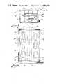
- FIG. 2is a front cross sectional view of the modular packaging system of FIG. 1, taken along line 2--2 of FIG. 1.
- FIG. 3is an exploded pictorial view of a single module embodying the present invention.
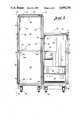
- FIG. 4is a side view of a single module with the exterior panel removed and portions broken away to show interior detail.
- FIG. 5is a top view of a single module with the top panel removed.
- FIG. 1shows a modular packaging system 10 embodying the present invention.
- the modular packaging system 10is made up of three assembled modules 12, 14, and 16, mounted on two bases 18 and attached together in a manner described below.
- the module 14rests directly on the top of the module 16, while the module 12 is attached to the sides of both the modules 14 and 16.
- the configuration of modules shown in FIG. 1is only one example of a modular packaging system according to the invention. After reviewing the following detailed description, it will be understood that an unlimited number of combinations of module sizes and configurations can be assembled to meet the needs of a particular user for a modular packaging system.
- each moduleis cuboid in shape and similar in construction, although the height, width and depth may be changed from module to module.
- a rigid cuboid frame 20is the principal structural component of the modular packaging system 10.
- the frame 20includes a pair of vertical side walls 22 and 23 held in spaced apart relation by four channel members 30, which connect the side walls 22 and 23 at their corners.
- Each of the side walls 22 and 23defines a return flange 25 extending continuously around the peripheral edge of the side wall.
- the return flangeincludes a first flange member 26 extending outwardly from the side wall 22 or 23, and a second flange member 27 extending from the outer edge of the first flange member toward the center of the side wall.
- the first flange member 26is made up of connected segments, a top segment 26a, front segment 26b, bottom segment 26c, and rear segment 26d.
- the second flange memberis a square flat piece lying in a single vertical plane, and is made up of coplanar segments, a top segment 27a, front segment 27b, bottom segment 27c, and rear segment 27d.
- the second flange member 27thus forms a side engagement surface for abutting the side of an adjacent module.
- the flange member 27 of the module 12engages exterior panels 60 (described below) which are attached to flange members 27 of both the modules 14 and 16 to act as a spacing panel.
- the respective flanges 27 of the adjacent modulescould be abutted directly against one another.
- the channel members 30 which connect the side walls 22 and 23 of each moduleinclude a flat channel "floor” member 31 and a flat channel side member 32.
- Each channel floor 31lies in either the top or bottom plane of its module, perpendicular to the plane of the side walls.
- Each channel sideextends inwardly from the channel floor in a vertical plane.
- Two channel floorslie in a common plane with the top segments 26a of the first flange members 26 of the side walls, thus forming therewith a top engagement surface.
- the other two channel floorslie in a common plane with the bottom segments 26c of the first flange members 26 of the side walls, thus forming therewith a bototm engagement surface.
- a top engagement surface of the module 16is fixed to a bottom engagement surface of the module 14 in FIG. 2.
- the channel sideslie in a common plane with a front segment 26b or rear segment 26d of the first flange members 26 of the return flanges 25, forming front and rear engagement surfaces which could be used to increase the depth of the modular packaging system by joining two modules front-to-rear.
- the engagement surfaces described aboveare preferably made smooth by machining or other appropriate process to provide a tight fit against other modules, and to receive beryllium copper gasketing if EMI/RFI shielding is desired.
- Adjacent modulessuch as modules 12, 14 and 16 are preferably joined by bolt and nut assemblies 34 which attach engagement surfaces of respective modules in abutting relationship.
- the frame 20 of each moduleis provided with bolt openings 35 along the engagement surfaces, that is, along the flange members 27 of the return flanges 25 (as shown in FIG. 4), and along the channel floors 31 of the connecting channel members 30 (as shown in FIG. 5).
- the openings 35can be spaced along the frame members where needed. For example, in the system of FIGS. 1 and 2 openings 35 must be provided to allow the modules 16 and 14 to be attached to the side engagement surface of the module 12.
- the openings 35preferably extend also through the side wall 22 or 23 so that the bolt 34 can be fastened from the inside of the module.
- Any exterior panel 60 between adjacent modulesis also provided with openings for the bolts 34.
- Those bottom engagement surfaces which rest on the bases 18can be bolted directly to the bases.
- the flat members 27, 31 and 32also include openings 36 used to affix decorative panels to the frame 20, as described below.
- Other openings in the frameinclude large openings 37 and smaller openings 38 in the side walls 22 and 23. When two modules are joined side-to-side, the large openings 37 are utilized to pull cables from one module to another.
- the smaller openingsare preferably distributed over the entire surface of the side walls and are used to attach hardware for supporting electrical components.
- FIGS. 3 and 5Examples of mounting hardware are shown in FIGS. 3 and 5, and include cross rails 40 for Eurocard circuit boards 45 (shown in outline), and cross rails 44 for inch cards 46 (shown in outline).
- Such cross rails 40 and 44extend between the side walls 22 and 23, and are held to the side walls by screws (not shown) extending through the side walls into the ends of the cross rails, or by bolts (not shown) extending through both the side walls and end portions of the rails.
- Such railsare normally placed adjacent to the front of the frame 20, and at a depth commersurate with the depth of the circuit cards in question.
- Fig. 5shows rails for supporting cards of differing lengths at different heights within the frame 20.
- Card guides 42extend between the front and rear rails 40 or 44, and slidably receive the circuit cards in a conventional manner.
- Vertical mounting rails 47 for standard 19 inch componentscan also be attached to the interior of the side walls 22 and 23.
- the rails 47allow such components to be inserted just as they would be into a conventional vertical cabinet.
- Examples of standard components mounted in a module according to the inventionare a fan tray 48 and a non-circuit board component chassis 49, shown in FIG. 2.
- the width of the frame 20can be varied to other standard (such as 24 inch) or non-standard dimensions.
- Frame heightsare preferably based on multiples of standard EIA/IEC increments of 1.75 inches or 44.45 mm.
- the present inventionutilizes all the space between the side walls for circuit boards.
- a conventional vertical cabinetwould be used to load a card cage between the vertical rails 47, losing the space occupied by the rails 47 and the card cage subframe.
- a module according to the inventionaccomplishes this efficiency, it is still versatile enough to accommodate standard 19 inch components.
- Each module or series of modules assembled into a modular packaging system 10can be efficiently covered by decorative panels.
- Side exterior panels 60can be screwed or bolted onto the flat flange member 27 using the openings 36.
- the panels 60include a retrn flange 62 which extends continuously around the panel 60 and fits matingly against the flange member 27 as shown best in FIG. 2. This construction avoids any exposed edges and provides attractive visual lines.
- Any module side that is not abutted against and attached to another modulepreferably is fitted with a panel 60 sized to match the dimensions of the module.
- Special size panelssuch as panel 61, shown in FIGS. 1 and 2, can be provided to cover less than a full module side.
- the panel 61is constructed similarly to the panels 60, and includes a return flange 62.
- a rear external panel 64is preferably provided, having a return flange 65, shown in FIG. 4, which engages rear segments of the first flange member 26 and coplanar channel sides 32.
- the rear panel 64can cover the entire rear of the frame 20, or a connector panel 68 can be provided to facilitate electrical connection between the components within the module and external components or power supplies.
- the connector panel 68can be bolted directly to the return flanges 25 of the side walls.
- a top exterior panel 70encloses the top of each exposed module in the preferred embodiment of the invention.
- the top panel 70preferably includes a return flange 71 extending around the sides and rear of the top panel 70.
- the front of the top panelis preferably even with the front side of the module, and includes an extension 73, best shown in FIG. 4.
- the extension 73covers the upper front channel member for a decorative effect.
- vent openings 72can be provided in the top panel 70.
- a module embodying the inventioncan include a pair of L-shaped door mounting brackets 80 attached to the front-facing channel sides 32 of the module, and extending a short distance away from the front plane of the frame 20.
- the side panels 60can be extended by the same distance beyond the front plane of the frame 20, as shown in FIG. 5.
- a door panel 82for instance a plexiglass panel, is fitted with vertical edge trim pieces 83 and 84 which are U-shaped and slidably receive the door panel 82.
- the edge trim piece 83defines a pair of hinge pins 86 at its upper and lower ends. The hinge pins 86 are received in openings in the mounting brackets 80.
- the trim piece 84can be fitted with a lock 87 capable of engaging the frame 20 to prevent unauthorized access to the components within the module.
- Each module of the modular packaging system 10is fitted with a separate door as shown in FIG. 1.
- the door panel 82can be made of aluminum if shielding is desired.
- the bases 18can be provided with wheel or caster assemblies 90, which are of conventional construction.
- the basesalso can be perforated or largely open for ventilation.
- the extension of the base beyond the front of the modules as shown in the drawingsenhances the stability of the system.
- a single large basecan be provided underlying more than one module.
- the desired individual modulessuch as the modules 12, 14 and 16 are arranged in the desired configuration on the appropriate number of bases 18 (two in FIG. 1) with the appropriate engagement surfaces in abutting relationship.
- Bolt assemblies 34are then used to attach the modules together and to fix the assembled modules to the base.
- side exterior panels 60can be installed between the side by side modules by attaching the panels to an engagement surface of one of the modules.
- Appropriate hardware for mounting electrical componentssuch as cross rails 40,44 and vertical mounting rails 47, are attached to the side walls 22 and 23 of each of the modules to accommodate the particular user's components.
- the exposed sides, backs, and tops of the modulesare covered by installing panels 60, 64 and 70. If a door is desired, the door mounting brackets 80 are installed prior to the top panel 70, with the hinge pins 86 of the door received in openings in the brackets 80. The extension 73 of the top panel is placed over a portion of the upper mounting bracket 80 as the top panel 70 is installed.
- the internal mounting hardwarecan easily be changed. Exterior panels can be removed easily to facilitate such work. Furthermore, if the user desires to enlarge the modular packaging system or rearrange the configuration of existing modules, the system can easily be broken down into the module frames and reassembled as desired, as described above.
- FIGS. 3 and 4can be utilized. Of course, additional modules can be attached to meet future needs.
- a modular packaging systemprovides a unique and efficient system for packaging electrical components.
- the advantages of the inventionare derived in important part from the use of self contained modules which directly receive electrical components and can be assembled together in any desired configuration.
- the inventioneliminates one level of conventional packaging, the card cage or subrack, resulting in a saving of the cost of the subracks themselves as well as a saving through more efficient use of the space within the primary frame.
- the flexibility of a system according to the inventionallows the user to add additional space for components without discarding an initial smaller configuration.
- the structure of the module frames and the exterior panelscooperate to enable the completed system to have a pleasing appearance.
Landscapes
- Engineering & Computer Science (AREA)
- Microelectronics & Electronic Packaging (AREA)
- Mounting Of Printed Circuit Boards And The Like (AREA)
Abstract
Description
Claims (3)
Priority Applications (1)
| Application Number | Priority Date | Filing Date | Title |
|---|---|---|---|
| US06/774,036US4699270A (en) | 1985-09-09 | 1985-09-09 | Modular packaging system |
Applications Claiming Priority (1)
| Application Number | Priority Date | Filing Date | Title |
|---|---|---|---|
| US06/774,036US4699270A (en) | 1985-09-09 | 1985-09-09 | Modular packaging system |
Publications (1)
| Publication Number | Publication Date |
|---|---|
| US4699270Atrue US4699270A (en) | 1987-10-13 |
Family
ID=25100053
Family Applications (1)
| Application Number | Title | Priority Date | Filing Date |
|---|---|---|---|
| US06/774,036Expired - Fee RelatedUS4699270A (en) | 1985-09-09 | 1985-09-09 | Modular packaging system |
Country Status (1)
| Country | Link |
|---|---|
| US (1) | US4699270A (en) |
Cited By (40)
| Publication number | Priority date | Publication date | Assignee | Title |
|---|---|---|---|---|
| US4938351A (en)* | 1989-06-20 | 1990-07-03 | International Business Machines Corporation | Modular electrical component packaging system |
| US5020866A (en)* | 1989-11-13 | 1991-06-04 | Gichner Systems Group, Inc. | Enclosure for housing electronic components |
| US5131543A (en)* | 1991-10-03 | 1992-07-21 | Roberts, Stephens, Van Amburg Packaging, Inc. | Reusable and recyclable packaging for shock and static sensitive objects |
| US5142445A (en)* | 1990-06-01 | 1992-08-25 | Sorensen Bradford T | Modular stackable interlocking storage cabinet for electronic components |
| US5159528A (en)* | 1990-12-07 | 1992-10-27 | Compuadd Corporation | Modular personal computer |
| USRE34393E (en)* | 1989-11-13 | 1993-09-28 | Gichner Systems Group, Inc. | Enclosure for housing electronic components |
| US5249685A (en)* | 1991-10-03 | 1993-10-05 | Roberts, Stephens, Van Amburg, Packaging Inc. | Reusable and recyclable packaging for shock and static sensitive objects |
| US5271152A (en)* | 1990-12-07 | 1993-12-21 | Compuadd Corporation | Process for making a computer tower chassis using modules |
| US5282114A (en)* | 1991-11-05 | 1994-01-25 | Codar Technology Inc. | Ruggedized computer assembly providing accessibility and adaptability to, and effective cooling of, electronic components |
| US5314276A (en)* | 1990-11-08 | 1994-05-24 | Barone Joseph P | Lading separating and bracing means |
| US5388939A (en)* | 1990-11-08 | 1995-02-14 | Barone; Joseph P. | Lading separating and bracing means |
| USD390835S (en) | 1996-10-16 | 1998-02-17 | Gichner Systems Group, Inc. | Cabinet for electronic components |
| US5947570A (en)* | 1997-10-10 | 1999-09-07 | International Business Machines Corporation | Modular cabinet assembly for a computer |
| US5957557A (en)* | 1996-08-05 | 1999-09-28 | Bulthaup Gmbh & Co. Kuchensysteme | System consisting of kitchen appliance housing units and/or kitchen units |
| US6195493B1 (en)* | 1999-05-21 | 2001-02-27 | Scientific-Atlanta, Inc. | Universal chassis for CATV headends or telecommunications company central office for optical electronic equipment |
| WO2002100701A3 (en)* | 2001-06-11 | 2003-07-17 | Frank A Ferraro | Moving cart assemblies |
| US20030168949A1 (en)* | 2001-12-28 | 2003-09-11 | Hales Robert J. | Extension cabinet for electrical systems and method |
| US20030224645A1 (en)* | 2002-05-31 | 2003-12-04 | Racksaver, Inc. | Rack mountable computer component power distribution unit and method |
| US20030223199A1 (en)* | 2002-05-31 | 2003-12-04 | Racksaver, Inc. | Rack mountable computer component and method of making same |
| US20040057216A1 (en)* | 2002-09-25 | 2004-03-25 | Smith John V. | Electronic component rack assembly and method |
| US20040065236A1 (en)* | 2000-12-14 | 2004-04-08 | Hans Langh | Transport container for sheets |
| US6801428B2 (en) | 2002-05-31 | 2004-10-05 | Racksaver, Inc. | Rack mountable computer component fan cooling arrangement and method |
| US6867966B2 (en)* | 2002-05-31 | 2005-03-15 | Verari Systems, Inc. | Method and apparatus for rack mounting computer components |
| US20050102918A1 (en)* | 2003-11-05 | 2005-05-19 | Richardson Joseph T. | Modular color pallet display system |
| US20060071581A1 (en)* | 2004-10-05 | 2006-04-06 | Harvey Stephen C | Stackable, interlocking carrying cases for making a modular desk having a removable desk top |
| US20060132003A1 (en)* | 1997-04-17 | 2006-06-22 | Kelley James O | Modular furniture system |
| US20070069491A1 (en)* | 2003-05-15 | 2007-03-29 | Ferraro Frank A | Moving cart assemblies |
| US7207449B1 (en)* | 2003-03-06 | 2007-04-24 | Greco David F | Anti-static storage shelves and assembly |
| KR100772084B1 (en) | 2002-05-31 | 2007-10-31 | 베라리 시스템즈, 인코포레이티드 | Computer component structure and its manufacturing method |
| US20070284973A1 (en)* | 2006-06-05 | 2007-12-13 | Jannifer Jones | Mobile modular furniture framework |
| US20110115351A1 (en)* | 2009-10-30 | 2011-05-19 | Argc, Llc | Modular Case Goods and Components |
| US20120306335A1 (en)* | 2011-06-03 | 2012-12-06 | Kendall Howard L.L.C. | Corner-Mount Electronics Cabinet |
| US20130099638A1 (en)* | 2011-10-21 | 2013-04-25 | Malgorzata Pala | Printer cabinet latch assembly |
| US20140027093A1 (en)* | 2012-07-25 | 2014-01-30 | Industrial Technology Research Institute | Air conditioning apparatus for use in information/data center |
| US20150368028A1 (en)* | 2014-06-23 | 2015-12-24 | Boe Technology Group Co., Ltd. | Packaging box for display panels |
| US20230073519A1 (en)* | 2021-09-08 | 2023-03-09 | Vertiv Corporation | Electronic equipment enclosure with enhanced mounting flexibility |
| US20230116870A1 (en)* | 2021-10-11 | 2023-04-13 | Dell Products L.P. | Multipurpose chassis front trim piece |
| USD987117S1 (en) | 2020-10-14 | 2023-05-23 | MillerKnoll, Inc. | Wall |
| US11760283B2 (en) | 2019-04-05 | 2023-09-19 | 901D, Llc | Modular packaging for rugged electronics enclosures |
| US11814839B2 (en)* | 2020-10-28 | 2023-11-14 | MillerKnoll, Inc. | Mobile wall including an alignment mechanism |
Citations (29)
| Publication number | Priority date | Publication date | Assignee | Title |
|---|---|---|---|---|
| US1404632A (en)* | 1922-01-24 | Oooooooooo | ||
| US3807572A (en)* | 1972-05-12 | 1974-04-30 | Pitney Bowes Inc | Adjustable compartment size storage unit |
| US3829190A (en)* | 1972-10-19 | 1974-08-13 | A Jackson | Cabinet prefabrication system |
| US3846002A (en)* | 1972-03-10 | 1974-11-05 | Floetotto | Building unit for furniture |
| US3848942A (en)* | 1973-03-22 | 1974-11-19 | L Fanini | Module for furniture development |
| US3857619A (en)* | 1974-02-08 | 1974-12-31 | Texstar Corp | Modular cabinet system |
| US3868158A (en)* | 1972-05-17 | 1975-02-25 | Honeywell Bull Sa | Module rack for connection boxes of printed-circuit cards |
| US3905662A (en)* | 1974-05-28 | 1975-09-16 | Stryker Corp | Combined cabinet and table |
| US3915307A (en)* | 1974-05-30 | 1975-10-28 | Saab Scania Ab | Holder for printed circuit boards |
| US3948581A (en)* | 1974-07-02 | 1976-04-06 | Helman Philip L | Knockdown furniture assemblies |
| US4099623A (en)* | 1977-09-08 | 1978-07-11 | Panel Controls Corporation | Circuit board storage cart |
| US4108514A (en)* | 1977-10-18 | 1978-08-22 | Dual Gebruder Steidinger | Phonostand |
| US4202586A (en)* | 1978-09-28 | 1980-05-13 | Oplinger Terry R | Stackable furniture modules having replaceable panels |
| FR2448880A1 (en)* | 1979-02-15 | 1980-09-12 | Ramond Marcel | Pre-fabricated modular furniture unit - is made of three shapes of sections assembled together by bars and formed of plates of specified dimensions |
| US4261464A (en)* | 1979-08-29 | 1981-04-14 | C. R. Daniels, Inc. | Tote box for carrying different length circuit boards |
| US4277120A (en)* | 1979-05-29 | 1981-07-07 | Drake Leo O | Printed circuit board storage cabinet |
| US4321654A (en)* | 1977-12-16 | 1982-03-23 | Fujitsu Limited | Frame unit for electronic communication devices |
| US4328517A (en)* | 1979-06-04 | 1982-05-04 | Hitachi, Ltd. | Channel selection apparatus for television receiver |
| US4328898A (en)* | 1979-12-04 | 1982-05-11 | Societa Italiana Telecomunicazioni Siemens S.P.A. | Frame for storing printed-circuit boards or the like |
| US4328897A (en)* | 1978-11-08 | 1982-05-11 | Vero Electronics Gmbh | Rack for accommodating circuit boards |
| US4407416A (en)* | 1980-07-16 | 1983-10-04 | Protronix, Inc. | Mounting frame system for circuit boards |
| US4426675A (en)* | 1982-04-05 | 1984-01-17 | Northern Telecom Limited | Carrier for circuit boards |
| US4433881A (en)* | 1981-11-16 | 1984-02-28 | Datapoint Corporation | Connecting mechanism for word processor - controlled printer output module cabinets |
| US4443046A (en)* | 1980-05-28 | 1984-04-17 | Knoll International, Inc. | Desk assembly |
| US4458813A (en)* | 1982-01-21 | 1984-07-10 | Superscope, Inc. | Housing for a video cassette playback machine |
| US4466049A (en)* | 1981-05-07 | 1984-08-14 | Cincinnati Milacron Industries, Inc. | Modular circuit board guide |
| US4478331A (en)* | 1981-07-09 | 1984-10-23 | Jean-Claude Robin | Container for printed-circuit boards |
| US4527222A (en)* | 1983-02-24 | 1985-07-02 | Menasha Corporation | Precision tote box insert for holding and locating printed circuit boards or the like |
| US4563722A (en)* | 1984-08-28 | 1986-01-07 | Plug-In Storage Systems, Inc. | Antistatic shelf for electronic circuit boards |
- 1985
- 1985-09-09USUS06/774,036patent/US4699270A/ennot_activeExpired - Fee Related
Patent Citations (29)
| Publication number | Priority date | Publication date | Assignee | Title |
|---|---|---|---|---|
| US1404632A (en)* | 1922-01-24 | Oooooooooo | ||
| US3846002A (en)* | 1972-03-10 | 1974-11-05 | Floetotto | Building unit for furniture |
| US3807572A (en)* | 1972-05-12 | 1974-04-30 | Pitney Bowes Inc | Adjustable compartment size storage unit |
| US3868158A (en)* | 1972-05-17 | 1975-02-25 | Honeywell Bull Sa | Module rack for connection boxes of printed-circuit cards |
| US3829190A (en)* | 1972-10-19 | 1974-08-13 | A Jackson | Cabinet prefabrication system |
| US3848942A (en)* | 1973-03-22 | 1974-11-19 | L Fanini | Module for furniture development |
| US3857619A (en)* | 1974-02-08 | 1974-12-31 | Texstar Corp | Modular cabinet system |
| US3905662A (en)* | 1974-05-28 | 1975-09-16 | Stryker Corp | Combined cabinet and table |
| US3915307A (en)* | 1974-05-30 | 1975-10-28 | Saab Scania Ab | Holder for printed circuit boards |
| US3948581A (en)* | 1974-07-02 | 1976-04-06 | Helman Philip L | Knockdown furniture assemblies |
| US4099623A (en)* | 1977-09-08 | 1978-07-11 | Panel Controls Corporation | Circuit board storage cart |
| US4108514A (en)* | 1977-10-18 | 1978-08-22 | Dual Gebruder Steidinger | Phonostand |
| US4321654A (en)* | 1977-12-16 | 1982-03-23 | Fujitsu Limited | Frame unit for electronic communication devices |
| US4202586A (en)* | 1978-09-28 | 1980-05-13 | Oplinger Terry R | Stackable furniture modules having replaceable panels |
| US4328897A (en)* | 1978-11-08 | 1982-05-11 | Vero Electronics Gmbh | Rack for accommodating circuit boards |
| FR2448880A1 (en)* | 1979-02-15 | 1980-09-12 | Ramond Marcel | Pre-fabricated modular furniture unit - is made of three shapes of sections assembled together by bars and formed of plates of specified dimensions |
| US4277120A (en)* | 1979-05-29 | 1981-07-07 | Drake Leo O | Printed circuit board storage cabinet |
| US4328517A (en)* | 1979-06-04 | 1982-05-04 | Hitachi, Ltd. | Channel selection apparatus for television receiver |
| US4261464A (en)* | 1979-08-29 | 1981-04-14 | C. R. Daniels, Inc. | Tote box for carrying different length circuit boards |
| US4328898A (en)* | 1979-12-04 | 1982-05-11 | Societa Italiana Telecomunicazioni Siemens S.P.A. | Frame for storing printed-circuit boards or the like |
| US4443046A (en)* | 1980-05-28 | 1984-04-17 | Knoll International, Inc. | Desk assembly |
| US4407416A (en)* | 1980-07-16 | 1983-10-04 | Protronix, Inc. | Mounting frame system for circuit boards |
| US4466049A (en)* | 1981-05-07 | 1984-08-14 | Cincinnati Milacron Industries, Inc. | Modular circuit board guide |
| US4478331A (en)* | 1981-07-09 | 1984-10-23 | Jean-Claude Robin | Container for printed-circuit boards |
| US4433881A (en)* | 1981-11-16 | 1984-02-28 | Datapoint Corporation | Connecting mechanism for word processor - controlled printer output module cabinets |
| US4458813A (en)* | 1982-01-21 | 1984-07-10 | Superscope, Inc. | Housing for a video cassette playback machine |
| US4426675A (en)* | 1982-04-05 | 1984-01-17 | Northern Telecom Limited | Carrier for circuit boards |
| US4527222A (en)* | 1983-02-24 | 1985-07-02 | Menasha Corporation | Precision tote box insert for holding and locating printed circuit boards or the like |
| US4563722A (en)* | 1984-08-28 | 1986-01-07 | Plug-In Storage Systems, Inc. | Antistatic shelf for electronic circuit boards |
Cited By (55)
| Publication number | Priority date | Publication date | Assignee | Title |
|---|---|---|---|---|
| US4938351A (en)* | 1989-06-20 | 1990-07-03 | International Business Machines Corporation | Modular electrical component packaging system |
| USRE34393E (en)* | 1989-11-13 | 1993-09-28 | Gichner Systems Group, Inc. | Enclosure for housing electronic components |
| US5020866A (en)* | 1989-11-13 | 1991-06-04 | Gichner Systems Group, Inc. | Enclosure for housing electronic components |
| US5142445A (en)* | 1990-06-01 | 1992-08-25 | Sorensen Bradford T | Modular stackable interlocking storage cabinet for electronic components |
| US5314276A (en)* | 1990-11-08 | 1994-05-24 | Barone Joseph P | Lading separating and bracing means |
| US5388939A (en)* | 1990-11-08 | 1995-02-14 | Barone; Joseph P. | Lading separating and bracing means |
| US5159528A (en)* | 1990-12-07 | 1992-10-27 | Compuadd Corporation | Modular personal computer |
| US5271152A (en)* | 1990-12-07 | 1993-12-21 | Compuadd Corporation | Process for making a computer tower chassis using modules |
| WO1992015186A1 (en)* | 1991-02-21 | 1992-09-03 | Leonard, Steven, S. | Modular stackable interlocking storage cabinet for electronic components |
| US5249685A (en)* | 1991-10-03 | 1993-10-05 | Roberts, Stephens, Van Amburg, Packaging Inc. | Reusable and recyclable packaging for shock and static sensitive objects |
| US5131543A (en)* | 1991-10-03 | 1992-07-21 | Roberts, Stephens, Van Amburg Packaging, Inc. | Reusable and recyclable packaging for shock and static sensitive objects |
| US5282114A (en)* | 1991-11-05 | 1994-01-25 | Codar Technology Inc. | Ruggedized computer assembly providing accessibility and adaptability to, and effective cooling of, electronic components |
| US5957557A (en)* | 1996-08-05 | 1999-09-28 | Bulthaup Gmbh & Co. Kuchensysteme | System consisting of kitchen appliance housing units and/or kitchen units |
| USD390835S (en) | 1996-10-16 | 1998-02-17 | Gichner Systems Group, Inc. | Cabinet for electronic components |
| US20060132003A1 (en)* | 1997-04-17 | 2006-06-22 | Kelley James O | Modular furniture system |
| US5947570A (en)* | 1997-10-10 | 1999-09-07 | International Business Machines Corporation | Modular cabinet assembly for a computer |
| US6195493B1 (en)* | 1999-05-21 | 2001-02-27 | Scientific-Atlanta, Inc. | Universal chassis for CATV headends or telecommunications company central office for optical electronic equipment |
| US20040065236A1 (en)* | 2000-12-14 | 2004-04-08 | Hans Langh | Transport container for sheets |
| WO2002100701A3 (en)* | 2001-06-11 | 2003-07-17 | Frank A Ferraro | Moving cart assemblies |
| US7134673B2 (en) | 2001-06-11 | 2006-11-14 | Ferraro Frank A | Moving cart assemblies |
| US20060038367A9 (en)* | 2001-06-11 | 2006-02-23 | Ferraro Frank A | Moving cart assemblies |
| US20050200090A1 (en)* | 2001-06-11 | 2005-09-15 | Ferraro Frank A. | Moving cart assemblies |
| US20030168949A1 (en)* | 2001-12-28 | 2003-09-11 | Hales Robert J. | Extension cabinet for electrical systems and method |
| US20060005984A1 (en)* | 2001-12-28 | 2006-01-12 | Hales Robert J | Extension cabinet for electrical systems and method |
| US6932446B2 (en)* | 2001-12-28 | 2005-08-23 | Robert J. Hales | Extension cabinet for electrical systems and method |
| US20050083651A1 (en)* | 2002-05-31 | 2005-04-21 | Smith John V. | Method and apparatus for rack mounting computer components |
| US20030224645A1 (en)* | 2002-05-31 | 2003-12-04 | Racksaver, Inc. | Rack mountable computer component power distribution unit and method |
| KR100772084B1 (en) | 2002-05-31 | 2007-10-31 | 베라리 시스템즈, 인코포레이티드 | Computer component structure and its manufacturing method |
| US6909611B2 (en) | 2002-05-31 | 2005-06-21 | Verari System, Inc. | Rack mountable computer component and method of making same |
| US20050024825A1 (en)* | 2002-05-31 | 2005-02-03 | Smith John V. | Rack mountable computer component fan cooling arrangement and method |
| US6836030B2 (en) | 2002-05-31 | 2004-12-28 | Verari Systems, Inc. | Rack mountable computer component power distribution unit and method |
| US6801428B2 (en) | 2002-05-31 | 2004-10-05 | Racksaver, Inc. | Rack mountable computer component fan cooling arrangement and method |
| US7420805B2 (en) | 2002-05-31 | 2008-09-02 | Verari Systems, Inc. | Method and apparatus for rack mounting computer components |
| US6867966B2 (en)* | 2002-05-31 | 2005-03-15 | Verari Systems, Inc. | Method and apparatus for rack mounting computer components |
| US20030223199A1 (en)* | 2002-05-31 | 2003-12-04 | Racksaver, Inc. | Rack mountable computer component and method of making same |
| US20040057216A1 (en)* | 2002-09-25 | 2004-03-25 | Smith John V. | Electronic component rack assembly and method |
| US7207449B1 (en)* | 2003-03-06 | 2007-04-24 | Greco David F | Anti-static storage shelves and assembly |
| US20070069491A1 (en)* | 2003-05-15 | 2007-03-29 | Ferraro Frank A | Moving cart assemblies |
| US20050102918A1 (en)* | 2003-11-05 | 2005-05-19 | Richardson Joseph T. | Modular color pallet display system |
| US7789472B2 (en)* | 2003-11-05 | 2010-09-07 | Behr Process Corporation | Modular color pallet display system |
| US20060071581A1 (en)* | 2004-10-05 | 2006-04-06 | Harvey Stephen C | Stackable, interlocking carrying cases for making a modular desk having a removable desk top |
| US20070284973A1 (en)* | 2006-06-05 | 2007-12-13 | Jannifer Jones | Mobile modular furniture framework |
| US20110115351A1 (en)* | 2009-10-30 | 2011-05-19 | Argc, Llc | Modular Case Goods and Components |
| US20120306335A1 (en)* | 2011-06-03 | 2012-12-06 | Kendall Howard L.L.C. | Corner-Mount Electronics Cabinet |
| US8894161B2 (en)* | 2011-06-03 | 2014-11-25 | Kendall Howard L.L.C. | Corner-mount electronics cabinet |
| US20130099638A1 (en)* | 2011-10-21 | 2013-04-25 | Malgorzata Pala | Printer cabinet latch assembly |
| US20140027093A1 (en)* | 2012-07-25 | 2014-01-30 | Industrial Technology Research Institute | Air conditioning apparatus for use in information/data center |
| US20150368028A1 (en)* | 2014-06-23 | 2015-12-24 | Boe Technology Group Co., Ltd. | Packaging box for display panels |
| US11760283B2 (en) | 2019-04-05 | 2023-09-19 | 901D, Llc | Modular packaging for rugged electronics enclosures |
| USD987117S1 (en) | 2020-10-14 | 2023-05-23 | MillerKnoll, Inc. | Wall |
| US11814839B2 (en)* | 2020-10-28 | 2023-11-14 | MillerKnoll, Inc. | Mobile wall including an alignment mechanism |
| US20230073519A1 (en)* | 2021-09-08 | 2023-03-09 | Vertiv Corporation | Electronic equipment enclosure with enhanced mounting flexibility |
| US12302527B2 (en)* | 2021-09-08 | 2025-05-13 | Vertiv Corporation | Electronic equipment enclosure with enhanced mounting flexibility |
| US20230116870A1 (en)* | 2021-10-11 | 2023-04-13 | Dell Products L.P. | Multipurpose chassis front trim piece |
| US11632873B1 (en)* | 2021-10-11 | 2023-04-18 | Dell Products L.P. | Multipurpose chassis front trim piece |
Similar Documents
| Publication | Publication Date | Title |
|---|---|---|
| US4699270A (en) | Modular packaging system | |
| US9755200B2 (en) | Equipment cabinet | |
| US4113331A (en) | Modular console enclosure with writing surface | |
| US5248193A (en) | Extruded enclosure for a computer system | |
| US20210321525A1 (en) | Integration cell for seismic electronic equipment rack | |
| US4669616A (en) | Rack for accommodating industrial electronic components | |
| US8925739B2 (en) | High-capacity computer rack with rear-accessible side bays | |
| EP0051024B1 (en) | Shelf unit for electronic communication devices | |
| US2959715A (en) | Instrument rack assembly | |
| US6201702B1 (en) | Computer with interchangeable covers and method for configuring a computer chassis | |
| US20200366108A1 (en) | Charging Locker | |
| US4984133A (en) | Unitized central electronics complex construction | |
| JPH0652829B2 (en) | Electronic cage | |
| CA2962518C (en) | Multi-piece rack shelf | |
| EP3474704A1 (en) | Integration cell for seismic electronic equipment rack | |
| US20050024842A1 (en) | Electronic enclosure and mounting arrangement therefor | |
| US4938351A (en) | Modular electrical component packaging system | |
| GB2124432A (en) | Printed circuit board rack | |
| JPH0220099A (en) | Structure for mounting electronic circuit device for mounting frame of electronic device | |
| US7002810B1 (en) | System and method for housing electronic equipment in a rack | |
| US8016126B1 (en) | Cabinet structures resistant to racking deformation for rack mounted computing systems | |
| JPH08213778A (en) | Rack for electronic circuit board and its supporter | |
| JP2001024366A (en) | Housing for mounting information processing equipment | |
| US7039291B1 (en) | Card rack | |
| JPH0534149Y2 (en) |
Legal Events
| Date | Code | Title | Description |
|---|---|---|---|
| AS | Assignment | Owner name:SCIENTIFIC-ATLANTA, INC., ONE TECHNOLOGY PARKWAY, Free format text:ASSIGNMENT OF ASSIGNORS INTEREST.;ASSIGNOR:BOHM, FRED;REEL/FRAME:004456/0831 Effective date:19850913 | |
| AS | Assignment | Owner name:UNION CORPORATION, THE, 50 WASHINGTON STREET, SOUT Free format text:ASSIGNMENT OF ASSIGNORS INTEREST.;ASSIGNOR:SCIENTIFIC-ATLANTA, INC.;REEL/FRAME:004781/0417 Effective date:19861023 | |
| AS | Assignment | Owner name:GICHNER SYSTEMS GROUP, INC., FORMERLY G.S.G. ACQUI Free format text:ASSIGNMENT OF ASSIGNORS INTEREST.;ASSIGNOR:UNION CORPORATION, THE;REEL/FRAME:005120/0734 Effective date:19890428 | |
| FEPP | Fee payment procedure | Free format text:PAYOR NUMBER ASSIGNED (ORIGINAL EVENT CODE: ASPN); ENTITY STATUS OF PATENT OWNER: LARGE ENTITY | |
| FPAY | Fee payment | Year of fee payment:4 | |
| FPAY | Fee payment | Year of fee payment:8 | |
| REMI | Maintenance fee reminder mailed | ||
| LAPS | Lapse for failure to pay maintenance fees | ||
| FP | Lapsed due to failure to pay maintenance fee | Effective date:19991013 | |
| STCH | Information on status: patent discontinuation | Free format text:PATENT EXPIRED DUE TO NONPAYMENT OF MAINTENANCE FEES UNDER 37 CFR 1.362 |