US4698664A - Audio-visual monitoring system - Google Patents
Audio-visual monitoring systemDownload PDFInfo
- Publication number
- US4698664A US4698664AUS06/707,836US70783685AUS4698664AUS 4698664 AUS4698664 AUS 4698664AUS 70783685 AUS70783685 AUS 70783685AUS 4698664 AUS4698664 AUS 4698664A
- Authority
- US
- United States
- Prior art keywords
- video
- memory array
- audio
- analog
- digital
- Prior art date
- Legal status (The legal status is an assumption and is not a legal conclusion. Google has not performed a legal analysis and makes no representation as to the accuracy of the status listed.)
- Expired - Fee Related
Links
- 238000012544monitoring processMethods0.000titleclaimsdescription17
- 230000015654memoryEffects0.000claimsabstractdescription102
- 238000005070samplingMethods0.000claimsdescription19
- 230000008859changeEffects0.000claimsdescription13
- 238000012937correctionMethods0.000claimsdescription13
- 238000000034methodMethods0.000claimsdescription13
- 230000000007visual effectEffects0.000claimsdescription12
- 238000006243chemical reactionMethods0.000claimsdescription11
- 239000003550markerSubstances0.000claimsdescription4
- 230000003252repetitive effectEffects0.000claimsdescription4
- 230000000737periodic effectEffects0.000claimsdescription3
- 230000003134recirculating effectEffects0.000claims2
- 238000001514detection methodMethods0.000claims1
- 239000002131composite materialSubstances0.000description9
- 238000010586diagramMethods0.000description9
- 239000011159matrix materialSubstances0.000description7
- 238000013144data compressionMethods0.000description4
- 230000006870functionEffects0.000description4
- 238000013459approachMethods0.000description3
- 238000003491arrayMethods0.000description3
- 238000007906compressionMethods0.000description3
- 230000006835compressionEffects0.000description3
- 230000000694effectsEffects0.000description3
- 230000007613environmental effectEffects0.000description3
- 238000012545processingMethods0.000description3
- 230000004044responseEffects0.000description3
- PEDCQBHIVMGVHV-UHFFFAOYSA-NGlycerineChemical compoundOCC(O)COPEDCQBHIVMGVHV-UHFFFAOYSA-N0.000description2
- 240000007320Pinus strobusSpecies0.000description2
- 238000004458analytical methodMethods0.000description2
- 230000008901benefitEffects0.000description2
- 239000003086colorantSubstances0.000description2
- 230000000994depressogenic effectEffects0.000description2
- 238000003780insertionMethods0.000description2
- 230000037431insertionEffects0.000description2
- 230000003287optical effectEffects0.000description2
- 230000002441reversible effectEffects0.000description2
- 230000005236sound signalEffects0.000description2
- OAICVXFJPJFONN-UHFFFAOYSA-NPhosphorusChemical compound[P]OAICVXFJPJFONN-UHFFFAOYSA-N0.000description1
- 230000004913activationEffects0.000description1
- 230000015556catabolic processEffects0.000description1
- 238000004891communicationMethods0.000description1
- 238000005056compactionMethods0.000description1
- 230000000295complement effectEffects0.000description1
- 238000010276constructionMethods0.000description1
- 238000006731degradation reactionMethods0.000description1
- 238000012217deletionMethods0.000description1
- 230000037430deletionEffects0.000description1
- 238000003745diagnosisMethods0.000description1
- 230000009977dual effectEffects0.000description1
- 239000000975dyeSubstances0.000description1
- 238000010894electron beam technologyMethods0.000description1
- 238000009432framingMethods0.000description1
- 230000008014freezingEffects0.000description1
- 238000007710freezingMethods0.000description1
- 230000000977initiatory effectEffects0.000description1
- 230000010354integrationEffects0.000description1
- 230000002452interceptive effectEffects0.000description1
- 230000009191jumpingEffects0.000description1
- 230000000670limiting effectEffects0.000description1
- 239000000203mixtureSubstances0.000description1
- 230000002688persistenceEffects0.000description1
- 230000000750progressive effectEffects0.000description1
- 230000035484reaction timeEffects0.000description1
- 230000002829reductive effectEffects0.000description1
- 239000004065semiconductorSubstances0.000description1
- 208000011726slow pulseDiseases0.000description1
- 239000007787solidSubstances0.000description1
- 230000003068static effectEffects0.000description1
- 230000000153supplemental effectEffects0.000description1
- 230000001360synchronised effectEffects0.000description1
- 238000003325tomographyMethods0.000description1
- 238000012546transferMethods0.000description1
- 230000009466transformationEffects0.000description1
- 230000007704transitionEffects0.000description1
- XLYOFNOQVPJJNP-UHFFFAOYSA-NwaterSubstancesOXLYOFNOQVPJJNP-UHFFFAOYSA-N0.000description1
Images


Classifications
- H—ELECTRICITY
- H04—ELECTRIC COMMUNICATION TECHNIQUE
- H04N—PICTORIAL COMMUNICATION, e.g. TELEVISION
- H04N5/00—Details of television systems
- H04N5/44—Receiver circuitry for the reception of television signals according to analogue transmission standards
- H04N5/4448—Receiver circuitry for the reception of television signals according to analogue transmission standards for frame-grabbing
- G—PHYSICS
- G11—INFORMATION STORAGE
- G11B—INFORMATION STORAGE BASED ON RELATIVE MOVEMENT BETWEEN RECORD CARRIER AND TRANSDUCER
- G11B27/00—Editing; Indexing; Addressing; Timing or synchronising; Monitoring; Measuring tape travel
- G11B27/02—Editing, e.g. varying the order of information signals recorded on, or reproduced from, record carriers
- G11B27/022—Electronic editing of analogue information signals, e.g. audio or video signals
- G11B27/024—Electronic editing of analogue information signals, e.g. audio or video signals on tapes
- G—PHYSICS
- G11—INFORMATION STORAGE
- G11B—INFORMATION STORAGE BASED ON RELATIVE MOVEMENT BETWEEN RECORD CARRIER AND TRANSDUCER
- G11B27/00—Editing; Indexing; Addressing; Timing or synchronising; Monitoring; Measuring tape travel
- G11B27/02—Editing, e.g. varying the order of information signals recorded on, or reproduced from, record carriers
- G11B27/022—Electronic editing of analogue information signals, e.g. audio or video signals
- G11B27/028—Electronic editing of analogue information signals, e.g. audio or video signals with computer assistance
- G—PHYSICS
- G11—INFORMATION STORAGE
- G11B—INFORMATION STORAGE BASED ON RELATIVE MOVEMENT BETWEEN RECORD CARRIER AND TRANSDUCER
- G11B27/00—Editing; Indexing; Addressing; Timing or synchronising; Monitoring; Measuring tape travel
- G11B27/10—Indexing; Addressing; Timing or synchronising; Measuring tape travel
- G11B27/34—Indicating arrangements
- H—ELECTRICITY
- H04—ELECTRIC COMMUNICATION TECHNIQUE
- H04N—PICTORIAL COMMUNICATION, e.g. TELEVISION
- H04N5/00—Details of television systems
- H04N5/222—Studio circuitry; Studio devices; Studio equipment
- H04N5/262—Studio circuits, e.g. for mixing, switching-over, change of character of image, other special effects ; Cameras specially adapted for the electronic generation of special effects
- H04N5/2624—Studio circuits, e.g. for mixing, switching-over, change of character of image, other special effects ; Cameras specially adapted for the electronic generation of special effects for obtaining an image which is composed of whole input images, e.g. splitscreen
- G—PHYSICS
- G11—INFORMATION STORAGE
- G11B—INFORMATION STORAGE BASED ON RELATIVE MOVEMENT BETWEEN RECORD CARRIER AND TRANSDUCER
- G11B2220/00—Record carriers by type
- G11B2220/90—Tape-like record carriers
Definitions
- the present inventionrelates to a monitoring system for electronic analysis of images and sounds. More particularly, the present invention relates to apparatus and methods for generating and putting out a matrix of image frames and/or sound segments in a unique visual presentation.
- Television imagesare typically formed as a series of scanned discrete image frames which are projected on a frame by frame basis on a suitable screen (e.g. the light generating phosphor display screen of a cathode ray tube).
- a suitable screene.g. the light generating phosphor display screen of a cathode ray tube.
- the persistence of the phosphors, and the insensitivity of the human eyecause an integration of the discrete frames into the appearance of a continuously moving image, usually the desired result.
- More sophisticated frame storesare known and employ both analog and digital techniques in rotating disk and solid state frame stores.
- digital frame storesWith the advent of high speed high capacity integrated circuit semiconductor memory, together with high speed analog to digital to analog conversion circuits and techniques, digital frame stores have supplemental analog stores for many applications, such as special effects generators in television studios wherein multiple images from multiple video sources may be combined digitally into a single frame time and put out as a viewable composite frame of multiple images.
- Split screen displayis one example.
- Film editinghas typically been carried out on a frame by frame (image by image) basis.
- an editing vieweris placed between two manually operable reels. The film is then inspected to locate edit points.
- a complicationarises if the film includes a sound track which requires normal operating velocity for intelligible playback.
- Squarekboxesemit low, guttural sounds and noises as the film moves over a sound track reader at very low speeds.
- Video tape editinghas employed both real time and slowed frame techniques. Electronic edit points are added to a control track, and automatic editing by insertion and deletion is carried out in accordance with the manually inserted control track edit points.
- TelecineIn some specialized applications such as the transfer of images from film to tape, called “Telecine", it is essential to detect each scene change so that the colors present in the new scene may be corrected.
- this telecine conversion operationhas been carried out manually with each new scene requiring freeze framing of the film transport and with new color correction parameter being then entered, along with the SMPTE time code into a color correction computer which automatically adjusts the hue and intensity of the colors of the video playback during a second pass in the telecine conversion.
- the telecine conversionis carried out only after each scene change has been located and color corrected manually.
- a general object of the present inventionis to overcome drawbacks and limitations of prior art image monitoring systems and methods.
- Another object of the present inventionis to provide a system which is simplified and more effective than other image monitor systems, and which has particularly useful applications in editing television program material, telecine conversion color correction, audio track editing and musical composition, and medical diagnosis.
- a further object of the present inventionis to generate a unique display of multiple successive picture images which simultaeously occupy substantially the entire useful display surface area of the display device and which present scene changes as a progressive rippling effect in both dimensions of the display surface area.
- One more object of the present inventionis to generate and display a unique video image cursor and to provide a control switching matrix for placing the cursor at a displayed image corresponding locationally to the relative location of an individual switch of the control switching matrix.
- Yet another object of the present inventionis to provide a multi-frame television monitoring system which monitors, stores and displays successive picture images and simultaneously accompanying audio track segments with a locally generated, unique audio cursor in the picture image and wherein the audio track segments accompanying a still-framed picture image are reproduced at normal voice/sound listening rates so that audio marking points may be precisely located.
- Yet one more object of the present inventionis to compress by pixel and line sampling and then store the compressed digitized picture images in a unique ring memory array holding a plurality of such images wherein latest frame writing operations are carried out during playback sweep blanking time intervals to avoid data write and readback conflicts during real time display of the compressed images.
- a monitoring systemincorporates the principles of the present invention with analog information such as television pictures and sounds, wherein information is divided into a series of blocks such as picture frames or audio time segments, each block being identifiable as such.
- the systemincludes an analog to digital converter connected to the source for converting the analog information into a digital stream of corresponding digital values.
- a ring memory arrayis connected to the analog to digital converter and it stores corresponding digital values.
- the arrayincludes address generation circuitry for generating addresses which progress through storage locations of the array in repetitive fashion and read/write control circuitry for replacing the oldest stored corresponding digital values with the latest corresponding digital values only during playback sweep blanking intervals.
- a freeze switchmay be operated to disable writing of latest corresponding digital values into the ring memory array.
- a digital to analog converteris connected to the memory array, and it converts the stored digital values to analog values and puts them out as such to a suitable analog display such as a television monitor.
- a block identifiermay be included for providing and putting out a block identification value for each block put out by the digital to analog converter, the block identifier being responsive to the freeze switch so that during cessation of writing, each block put out bears the same identification value.
- a temporary storage memorymay be connected to the analog to digital converter for temporarily storing the digital stream at a storage rate related to the video rate of the analog data stream.
- the ring memory array meansis then connected to the temporary storage memory and it stores during write operations a plurality of successive video frames comprised of sampled ones of the digital values from the temporary storage memory in accordance with a sampling rate which determines the minimum number of successive picture frames to be stored in the ring memory array.
- a video cursor generatormay be connected to the system for generating a cursor marker for a selected one of the plurality of video frames stored in the ring memory array and read by the read control circuitry.
- the cursor generatorcomprises a switch array for switchably controlling the location of placement of the cursor on a television display screen.
- the switch array meansincludes a switch dedicated to each video frame location. The switch array is laid out to correspond to the presentation of the plurality of video frames on the picture screen.
- a data stream of analog informationtypically a sound track audio information component, has blocks thereof defined by time increments, each increment having its own time block identifier.
- the systemmay further comprise an audio analog to digital converter connected to the audio source for converting an audio component of the analog information into a digital stream of corresponding digital values, an audio ring memory array connected to the audio analog to digital converter for storing the corresponding digital audio values and including an audio address generation circuit for generating addresses which progress through storage locations of the memory array in repetitive fashion and audio read/write control circuitry for replacing the oldest stored corresponding digital values with the latest corresponding digital values, and further including an audio freeze switch for disabling writing of latest corresponding digital values into the array.
- An audio digital to analog converteris connected to the audio memory array for converting the stored digital values to analog values and for putting them out.
- An audio block identifiermay be provided for putting out a unique block identification value for each audio block put out by the audio digital to analog converter, the block identifier being responsive to the freeze switch so that during cessation of writing of the audio ring memory, each audio block put out bears the same identification value.
- An audio visual cursor generatorgenerates a video cursor corresponding to the audio blocks.
- a cursor control switchswitches cursor output between the video cursor generator and the audio visual cursor generator.
- the systemfurther comprises a color separator connected to the signal source.
- the color separatorseparates the color television signal into a plurality of signal components, each having a luminance frequency bandwidth.
- the systemthen includes a plurality of analog to digital converters, line stores, ring memory arrays, and digital to analog converters, one each being connected in a channel for each signal component.
- a color combineris connected to the digital to analog converters and combines signal components into a composite color television signal.
- the video display of the present inventionsimultaneously displays a plurality of successive video picture frames occupying substantially the entirety of the useful display area of television picture screen.
- the displayis generated by a method comprising the steps of:
- N/X of the samplesin a multiple-frame array memory wherein X is an integer corresponding to the number of frames to be displayed in the line dimension and N equals the number of pixels in a line of video;
- Lequals the total number of lines per image and wherein Y equals the number of frames to be displayed in a dimension normal to the line dimension;
- the preferred image displaycomprises a plurality of rows and columns of picture frames wherein the region displaying the most recent frames is located in a corner of the television picture screen and scrolls from column to column in each row and row to row. Thus, the region displaying the oldest frame is located in the corner of the picture screen opposite to the corner displaying the most recent frame.
- This display arrangementthereby generates a unique bi-dimensional ripple pattern with each change of picture scene.
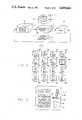
- FIG. 1is an overall environmental block diagram of an audio-visual monitoring system incorporating apparatus and principles in accordance with the present invention.
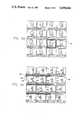
- FIG. 2is an enlarged diagrammatic view of a visual display appearing on a television monitor depicted in FIG. 1 and illustrative of principles of the present invention.
- FIG. 3is an enlarged top plan view of a control panel of the audio-visual monitoring system set forth in FIG. 1.
- FIG. 4is an overall electrical block diagram of the monitoring system depicted in FIG. 1.
- FIGS. 5A and 5Bare time sequential television picture frame graphs of a television monitor display illustrating particularly the visual and audio cursors generated by the system set forth in FIG. 4.
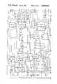
- FIGS. 6a, 6b, 6c, 6d, 6e, 6f, 6g, 6h and 6icomprise a more detailed electrical schematic and block diagram of the memory element 100 of the system depicted in FIG. 4.
- FIG. 6sets forth an overall layout plan for FIGS. 6a through 6i and FIG. 6 should be referred to when considering the disclosures of these figures.
- FIG. 1An audio-visual monitoring system 10 incorporating the principles of the present invention is depicted in the environmental block diagram of FIG. 1.
- the system 10is contained within a unitary housing 12 to which a control console 14 and a color television display monitor 16 are attached.
- the monitor 16includes audio channel playback facilities in order to provide both audio and video reproduction.
- the monitor display screen 18is shown subdivided into a matrix of e.g. 16 separate successive image frames 20a, 20b, 20c, 20d, 20e, 20f, 20g, 20h, 20i, 20j, 20k, 20L, 20m, 20n, 20o and 20p.
- These frames 20are reproduced with symbolic picture content for purposes of illustration in the enlarged picture diagram of FIG. 2.
- the lower right-hand corner frame 20ae.g.
- the display 18contains the most recent frame, and the upper left-hand corner frame 20p e.g. contains the oldest frame although other bidimensional image patterns may be employed.
- the display 18presents 16 sequential frames which ripple in a sinuous, snake-like ripple pattern during scene changes, with the frames entering the display 18 at the lower right-hand corner, advancing to the left along the bottom row, jumping to the next row above on the right edge and advancing, frame by frame to the left, and so on, until the oldest frame at the upper left hand corner is reached.
- the display 18presents approximately one half second of television in real time.
- the sinuous ripple patternshown in FIG.
- Each frameis provided with a superimposed sequential time code 21a, 21b, 21c, 21d, 21e, 21f, 21g, 21h, 21i, 21j, 21k, 21l, 21m, 21n, 21o and 21p as shown in FIGS. 2 and 5.
- the entire programis time coded in a conventional manner so that each successive frame carries a successive time code. In this manner, an edit may be carried out automatically, once the frame time codes of the appropriate editing locations have been ascertained and put out to responsive external equipment, such as a telecine color correction computer.
- the system 10is included within a television editing facility which further includes a source of television signals, such as a video tape recorder 22 and also an editor 24.
- a source of television signalssuch as a video tape recorder 22 and also an editor 24.
- Many other applications for the system 10are known such as color correction in tele-cine conversion systems, medical diagnostics as with x-ray radiopaque dyes in the bloodstream and so forth; the television editing environment is thus presented by way of example and not by way of limitation of the scope of the invention.
- Controls for the system 10are contained on the control console 14. These operator activated controls, illustrated in FIG. 3, include a bi-directional joystick 26 which operates in freeze mode to reverse the display of frames 20 in a left-ward position 28 and which operates to advance the display of frames 20 in a forward direction in a right-ward position 30. Below the joystick 26 are two switches: an audio-video select switch 32, and a freeze switch 34.
- the audio-video select switch 32enables the system 10 to switch between audio time segment display and video frame display. The switch 32 determines whether the video cursor (FIG. 5A) or the audio cursor (FIG. 5B) will be put out and displayed to the operator.
- the freeze switch 34enables the operator to stop the program material from being loaded into the system, thereby enabling the operator to analyze the frames and corresponding audio segments in detail by e.g. moving them back and forth with the joystick 26.
- This feature of the present inventionis particularly useful in tele-cine conversion systems wherein it is necessary to analyze each video scene for color content and provide color correction manually or automatically tailored to each different scene during film to tape and tape to film conversions.
- automatic color correction systemsthe time code corresponding to each scene change is entered into the color correction computer. Unless a sophisticated software control program is available and used, each scene change must be manually detected and signalled by the viewing operator.
- the time codeis then sent out to the color correction computer and color correction values for the new scene may be manually or automatically provided for each new scene.
- Human operator reaction time to scene changeshas been discovered to be approximately eight frames.
- typical operator reaction at the frame freeze switch 34will occur when the scene change has progressed half way through the rippling frame progression on the screen 18.
- the joystickmay be used to recall or center the scene change, providing it remains within the 32 frames actually on store in the system memory after the freeze control 34 is activated. It has been found that the system 10 has reduced telecine conversion color correction time for feature length films from approximately twelve hours to approximately six hours.
- a matrix of 16 switches 36a, 36b, 36c, 36d, 36e, 36f, 36g, 36h, 36i, 36j, 36k, 36L, 36m, 36n, 36o and 36pis provided on the console 14 to enable the operator to select one of displayed frames 20.
- Each switch 36corresponds to a picture frame 20 having the same relative location in the matrix 36.
- switch 36acorresponds to displayed picture frame 20a
- switch 36pcorresponds to displayed frame 20p.
- One of the switches 36may be depressed by the operator to create a symbolic video cursor border 38 around the corresponding frame of the display (FIG. 5A).
- a signal border 38is formed around the picture frame 20i, as shown in FIG. 2.
- the bordermay be white or some preselected color which stands out to the operator.
- the purpose of the signal borderis to put out to the editor 24 the time code of the frame selected as e.g. an edit point, typically the first frame of a video cut in picture content in the telecine application.
- a graph of a matrix of frames including one having the video cursoris included herein as FIG. 5A.
- a frame store within the system 10stores e.g. 32 successive picture frames, some number greater than the diplay capability of the video display 18 (32 frames representing one second of real time television).
- An operatoris then able, by operating the joystick 26, to move the display back and forth over the e.g. 32 frames stored in the memory.
- the freeze switch 34controls write operations of the internal memory so that when the system 10 is in the freeze mode, the memory stops writing new frames into the memory, thereby enabling the operator to place the display at any desired successive location among the stored 32 frames by manipulation of the joystick 26 in either the reverse 28 or forward 30 directions.
- the joystick 26operates progressively so that the amount of deflection thereof is related directly to control the speed of stored frame manipulation and movement.
- a row of four switches 40, 42, 44 and 46 along the top left portion of the console 14completes the operator controls.
- the switches 40-46enable the operator to select the video frame sampling rate.
- the switch 40selects a one to one sample rate
- the switch 42selects a one to two sample rate, meaning that the display 18 displays every other real-time picture frame
- the switch 44selects a one to four sample rate
- the switch 46selects a one to 16 frame sample rate, meaning that only one in 16 frames is sampled and displayed.
- a video input selector 52selects a video signal from a variety of sources which may include a video tape or cassette recorder/player 54, a video camera 56, a tele-cine converter system 58, an x-ray machine 60, a broadcast tuner-receiver 62 or an optical data recorder/player 64, for example.
- the video input signalmay be composite color or monochrome and should follow the RS 170 standard (U.S.) or the CCIR standard (European) signal format and timing relationship, although other signal (synchronizing pulse) formats may be employed, depending upon the application. While the system 10 is illustrated in FIG. 4 as handling NTSC composite color, in some applications such as picture editing a monochrome signal has been found to be entirely satisfactory. If only monochrome signal processing isrequired, the system 10 may be simplified by omission of the color component memory units described hereinafter.
- the first processing stepoccurs at a time code to video adder block 66.
- This blockfunctions to add a standard time code, such as the SMPTE time code, to each video frame, providing a switch 68 is set as shown in FIG. 4 and further providing that a suitable time code signal stream is provided e.g. from an internal time code generator 70, or from a selected external time code source.
- the external time code sourcesmay include an external generator 72, a time code track of a video or audio recorder/player 74, or a broadcast tuner/receiver 76, and one of them may be selected through a time code selector 78.
- An internal/external time code selector switch 80selects between the internal generator 70 and the selector 78.
- the selected time code signal streampasses through a time code reader and serial to parallel converter block 82 and thence through a time code to character generator converter 84 before reaching the adder circuit 66.
- the time code reader-converter 82deciphers the time code into storable binary informaton and reformants the resultant binary into a parallel data word for each frame.
- the time code to character generatorconverts each time code into a pixel display suitable for insertion into the analog video data stream entering the time code to video adder block 66.
- a jack 86provides an input to an external reference video source, such as a synchronizing generator, and this video is input through a relay contact set 88a to the adder 66 when the freeze control 34 is actuated by the operator and the system 10 enters the video frame freeze mode.
- An optional analog video output node 90is provided for e.g. an external monitor display of the incoming video signal with time coding added thereto.
- a standard hetrodyne color decoder 92receives the incoming composite video from the adder 66 and also receive a color subcarrier signal from an internal color synchronizing pulse generator 94.
- the decoder 92functions to separate the color composite video into a luminance or green (Y) component, a red minus green (R-Y) component and a blue minus green (B-Y) component.
- the luminance component (Y)enters a luminance analog to digital converter 96 where it is converted to a digital data stream at a sampling rate of e.g. 512 samples per line. Each sampled picture element (pixel) is converted to a binary value in a range from zero to 255 (8 bit data word per pixel or any other useful bit/pixel range).
- the memory array 100includes an internal address generator 102 and also a read/write control 104.
- the address generatorgenerates suitable addresses for storing and reading out the digitized and selected video pixels and lines in appropriate locations of the array 100.
- the array 100is configured as a giant ring counter having 32 separate compartments.
- the address generator 102 and the read/write control 104cooperate so that one compartment is being written while the other thirty one compartments are readable (although only sixteen are being read at any one time for display purposes).
- the location corresponding to the newest frame 20ais being written over the oldest frame in a progressive fashion with writing occurring only during the horizontal blanking interval.
- playbacke.g.
- one half of the sampled pixels stored in the line memory 98are written to the appropriate portion of the new frame compartment of the array 100 during the horizontal blanking interval following the first line scan.
- the second half of the sampled pixelsare written during the second horizontal blanking interval.
- This sequenceis then repeated at the 5 th, 9th, 13th etc. lines so that by the time that all lines have been read out in playback, a new frame has been completely stored in the selected new frame compartment of the array 100, with all writing operations having been carried out during the selected horizontal blanking intervals of the frame, as just explained.
- the memory array 100 and its related control circuitry 102, 104is hereinafter shown and described in greater detail in connection with FIG. 6.
- the array 106stores the (R-Y) color component, and it includes its own address generator 108 and read/write control 110.
- the array 112stores the (B-Y) color component and it includes its own address generator 114 and read/write control 116.
- a (R-Y) analog to digital converter 118receives the (R-Y) component from the color decoder 92 and converts the analog line subcarrier component signal into e.g. 512 samples. Every fourth sample is stored in a (R-Y) line store 120. The stored, sampled digitized (R-Y) digital values are then stored in the (R-Y) array 106 in synchronization with the storage of the luminance (Y) values in the memory 100.
- a (B-Y) analog to digital converter 122 and associated (B-Y) line store 124operate in the same manner as the converter 118 and store 120 to digitize, sample and put out selected (B-Y) values to the memory array 112.
- a time code memory array 126is provided for storing a time code corresponding to each frame being stored in the array 100.
- the time code memory arrayhas or needs only 32 memory locations for video only, 128 for 4 seconds of audio, one corresponding to each frame stored in the array 100.
- the time code memory array 126includes suitable address generation 128 and read/write control 130 circuitry in accordance with well known principles and further in consonance with the structure and operation of the address generator 102 and read/write control circuit 104 described in greater detail hereinafter.
- a time code parallel to serial converter 132converts real time or stored time codes into serial format and put the serialized time code stream out at an output 134 for connection to e.g. a color correction computer or television editing computer, depending upon the environmental application of the system 10.
- the time code input to the converter 132is selected through relay contacts 88b which operate in response to activation of e.g. the freeze switch 34.
- the time code put out by the converter 132comes from the time code memory array 126. Normally, the time code is put out directly from the time code reader 82.
- the system 10includes a video cursor generator 136 and an audio cursor generator 138.
- the video cursor generator 136generates the visual border 38 which may be selected for a particular frame 20, as shown for the frame 20i in FIG. 2.
- the audio cursor generator 138generates as a visual cursor a series of vertical lines in a horizontal line (FIG. 5B). Each bar corresponds generally to the picture frame coincident with that portion of the audio sound track.
- An adjacent barcomprising a white segment on the left and a dark segment on the right, or vica versa, is used to point to a particular vertical bar which is the selected audio point.
- the joystick 26may be used to extend the white segment to a particular vertical bar in order to adjust the edit point.
- the time code for that bar and frameis automatically put out. It should be understood that the operator can hear the audio information stored in the audio memory (up to four seconds) in real time playback up to the point where the lower white cursor ends. In this way a very precise audio edit is achievable.
- the digital video signals from the (Y) video memory array 100 along with digital video signals corresponding to the video cursor 38 from the video cursor generator 136 and an audio cursor as described from the audio cursor generator 138are combined together in a border adder and audio cursor adder circuit 140.
- a control signal to circuit 140 from the control panel 14causes the adder circuit 140 to insert either the video cursor or the audio cursor into the luminance video data stream, depending upon whether video or audio is selected at the cursor select switch 32 and further depending upon the particular signal compression rate as established by the selected one of the four switches 40, 42, 44 or 46.
- a digital to analog converter 142such as type TRW 1016 manufactured by TRW, or equivalent, converts the resultant video signal put out by the adder into an analog signal stream.
- digital to analog converters 144, 146convert the color components from the arrays 106, 112, respectively, into synchronized analog signal streams.
- the three analog signal streamsare recombined into composite color in an encoder block 148.
- a processing amplifier 150adds appropriate processed synch signals from the generator 94 to the color video, amplifies the video and puts it out at an output node 152.
- An OR gate 154selects frame freeze data from a plurality e.g. 156, 158 or 160 of external frame freeze initiating sources which may be the manual push button 34, a time code decoder, a color hue detector (since change in hue often accompanies scene change), a sound level or pitch detector, a video luminance level detector, a periodic oscillator, a video motion detector, or a composite of these sources.
- the OR gate 154operates the relay 88 whose contact sets have previously been described.
- the joystick control 26is implemented with analog resistances which produce values which are converted to digital and are then applied to the address generators of the memories 100, 106, 112 and 126 so that stored frames may be scrolled back and forth while the system 10 is in freeze mode by joystick angle.
- the system 10includes an audio signal storage path.
- This pathis implemented with an audio source selector 156 which selects analog audio from an audio track 158 of a magnetic recorder/player, a microphone 160, a tele-cine audio channel 162, a broadcast tuner/receiver 164, or an optical recorder/player 166, for example.
- the selected audiois sampled and digitized in an audio analog to digital converter 168.
- the converter 168may be implemented with two integrated circuits: and AMD 2502 successive approximation register and an AMD 6071 companding digital to analog converter, both made by Advanced Micro-Devices, or equivalent.
- a four second audio memory array 170is implemented in similar fashion as the memory 100, previously described.
- the audio memory array 170includes an address generator 172 and a read/write control 174 which operate in the same manner as the generator 102 and control 104, respectively.
- a digital to analog converter 176such as type AMD 6071, converts the digitized audio into an analog audio stream and puts it out at an audio output node 178.
- the visual cursor corresponding to the audio signal componentmay be of several types. As already explained, one preferred type, shown in the graph set forth as FIG. 5B, employs two horizontal bars 180 and 182 imposed along the bottom of the video frames.
- the top horizontal barsets forth a series of equally spaced apart visual serrations 184 which constantly move. Each serration corresponds to a video frame (and time code).
- the bottom bar 182comprises a white component and a black component.
- the white component 184corresponds to the sound actually heard in conjunction with the displayed video frames.
- the black component 186marks the cutoff location of the audio track. In the freeze mode the white-black ratio of the bottom bar 182 may be adjusted by the joystick 26 when audio cursor mode is selected at the switch 32.
- the time code for the video frame(as denoted by a serration in the bar 180) is put out at the time code output 134 to appropriate external editing equipment.
- An advantage of the audio storage feature of the system 10is that the audio segment in storage 170 may be played out at real time rates, over and over, until an appropriate edit point is located. This is to be contrasted with prior art methods in which audio reproduction was e.g. a function of velocity of film over a sound track pickup in a film editor.
- the time code indicated visually in the frame adjacent to the transition between white 184 and black 186is the actual time code which exits the time code output node 134.
- FIGS. 6a, 6b, 6c, 6d, 6f, 6g, 6h and 6iA detailed schematic diagram for the subfield memory array block 100, including the address generator 102 and the read/write control 104 is set forth as a series of figures, FIGS. 6a, 6b, 6c, 6d, 6f, 6g, 6h and 6i. These nine figures should be read together as a single diagram in accordance with the overall layout arrangement set forth in FIG. 6, and interconnecting common signal paths bear the same two letter reference designators on each of the figures. A detailed description of each component will not be provided herein, as sufficient information to duplicate the circuitry will be apparent to those skilled in the art from a thoughtful consideration of the schematic diagram itself.
- the memory array block 100(FIGS. 6h and 6i) is preferably implemented as a 512 by 512 (256k) by eight bit frame buffer configured to operated in a read, modified write mode (i.e. while reading, writing may occur immediately after the read at the same location, but not at a new or different location).
- the memory arrayis preferably implemented with 64K by one bit dynamic memory chips (type 4164, for example).
- a multiplexed addresing systemis employed which first generates and clocks an eight bit code for the row address to the array; an eight bit column address is then generated and clocked to the array.
- the line store 98stores the line. A selected sampled portion of the line being stored in the line store 98 is then put out during the horizontal blanking interval in real time. All writing into the memory array 100 of the selected sampled line portion data occurs during the horizontal blanking time interval. Thus, for each line every fourth pixel is selected and written. In like manner, every fourth line is written.
- the memory array 100is being constantly cycled and read in real time so that the data being put out as an eight bit stream comprises each pixel value being scanned and illuminated on the picture screen 18 of the monitor 16.
- the newest picture informationi.e. for frame 20a is written into that portion of the array in place of the oldest picture information (which is sixteen frames after the oldest display image, frame 20p, since the array 100 holds e.g. 32 picture frames, or approximately one full second of real time video information).
- the address generator 102includes counters which are incremented to cause the array to be continually cycled during the read out operation.
- a relative address starting pointis zeroed for each frame.
- the line addressis incremented by one.
- Each scanning line stored in the memory 100contains pixel values for four frames, e.g. frames 20a, 20b, 20c and 20d.
- the pixel values read out of the memory 100are first for a line of frame 20d, an aligned line of frame 20c, an aligned line of 20b, and finally an aligned line of 20a, the right-most frame.
- the real time scanning lineone half of the addresses for the latest frame 20a would be written, as previously explained. Then the next line is scanned which displays the four lines of the four frames, and so forth.
- the address generator 102(FIGS. 6a, d and e) includes a master latch control timing generator 202, which enables data input latches 204, 206, 208 and 210 and which enables data output latches 212, 214, 216 and 218.
- This generator 202is essentially the heart of the frame buffer array 100. Eight data words (pixels) are written into the input latches 204-210 and eight data words are also written into the four output latches 212-218.
- the generator 202generates the necessary strobe timing for the input and output latches.
- FIG. 6eFour master read/write address counters 222, 224 226 and 228 (FIG. 6e) are commonly clocked at an appropriate pixel sample rate via a signal on a line from an inverter 7B (FIG. 6d). This rate is derived in part in response to the even field pulse signal from the synchronizing generator 94. A signal on a line CB clears the counters 222, 224, 226 and 228 at the beginning of each frame. In regular television, the picture is interlaced, i.e. scanned as 256 lines in an even field and then scanned as 256 lines between the even field lines in an odd field. The present invention stores only even field data (or odd field data, depending upon a jumper). Thus, the use of the even field pulse. It is to be understood that the terms frame, field and subfield are given equivalent meanings herein and that a stored field is read twice to achieve interlacing of the frame.
- the countersare paired into two sets. Output from the first set 222, 224 is latched into a latch 230. Output from the second set (FIG. 6e) 226, 228 is latched into a latch 232. At the end of a real-time horizontal line the addresses are loaded into the latches 230, 232 and held. A temporary buffer 234 holds data from one of the latches 230, 232. This buffer circuit 234 allows the counters 222 through 228 to operate as two separate counter chains.
- a video border cursor generator 236is implemented with the array of exclusive-or gates configured as shown in FIG. 6e. This video border cursor generator 236 is connected to the master counters 222 and 226 in order to receive the pixel and line addresses of a selected subframe 20a-20j and generate a white border at the periphery thereof.
- a data comparator 237determines which subframe will be bordered by the cursor.
- the count from a subframe counter 248(FIG. 6f) is added in an adder 238 to the count from the counter 224 (one quarter and one half line) and also the count from the counter 228 (which is one quarter field and one half field).
- Three selectors 240, 242, and 244select between normal read address and the most current subframe address which will have a write following a read.
- the values from the counter 222 and from the selectors 240, 242 and 244are then put out to a monolithic address controller 246 (FIG. 6g), such as the Texas Instruments' type TMS 4500A Dynamic RAM Controller, or equivalent, as shown in FIG. 6e.
- the controller 246additionally generates the necessary refresh pulses for the dynamic memory array.
- the subframe location counter 248, FIG. 6fkeeps track of the location of the subframe to be written to during read of each horizontal line.
- a one-bit toggle gate 250may be used in addition to or in lieu of the joystick 26 to toggle the address selector 244 so that the first 16 or the second 16 of the stored 32 frames (or subframes, the terms being used interchangeably herein) will be put out to the monitor 16.
- Synchronizing pulses including horizontal synch and vertical synchare supplied to the memory array 100 from the synchronizing generator 94.
- the horizontal drive pulsesenter a counter chain comprising counters 252, 254, 256 and 258 (FIG. 6c) which are configured to divide the horizontal drive rate by 512.
- a 10 megahertz clock signalenters a counter chain comprising counters 260, 262, 264 and 266 (FIG. 6a) which provides two counts, a 512 count for line read and a 64 count for writing which occurs during the horizontal blanking interval.
- a logic arraycomprising gates 268, 270, 272 and 274 controls switching of the counter chain between 512 and 64.
- a timing pulse generatorcomprises a chain of ripple latches 276, 278, 280, 282 and an exclusive OR gate 284 (FIG. 6a). This generator receives the horizontal pulse from the counter 258 and develops necessary timing pulses.
- a shift register 286generates a pulse pair which switches the address master counters from read to write mode at the end of each line.
- Three gates 288, 290 and 292provide a slight (10 ns) delay to the signals from the register 286 so that the control signals arrive at the counting chain in proper time relationship.
- a line store timing circuit 294.Comprising a plurality of gates arranged as shown at the lower right of FIG. 6b, controls the writing of every fourth pixel into the memory array.
- the circuit 294controls two counters 296, 298 (FIG. 6g) which generate line store addresses. These line store addresses are applied to two line store memories 300, 302 which implement the line store 98. Every fourth pixel stored in the memories 300, 302 in real time is strobed onto the data input bus to the latches 204-210 during the horizontal blanking interval.
- Input data from the control panel 14enters the control circuitry through a latch 304 (FIG. 6b).
- a controllable countercomprising chips 306 and 308 responds to input from the frame sampling rate switches 40-46 on the control panel 14.
- Vertical driveenters a counting chain comprising flipflops 310, 312, 314, 316, 318, 320, 322 configured as shown on FIG. 6b.
- Various pulses dervied from the vertical interval rateare generated by this counting chain.
- the clock for clearing the master counters at frame timeis derived by a chain comprising latches 324, 326 and gate 328 (FIG. 6c) which operate from information derived from the vertical and horizontal drive pulses.
- a wide composite blanking signalis available at the line CA (FIG. 6b) for external synchronizing purposes.
- FIG. 6cAn interface circuit for the joystick 26 is depicted in FIG. 6c.
- voltage values from the joystick 26are applied to two comparators 330, 332.
- the complementary digital outputs from the comparators 330, 332are applied to a comparator 334.
- This comparator 334generates an output on a line which is combined with a control panel bit from the latch 304 in a gate 6F (FIG. 6c).
- the gate 6Foperates the subframe location counter 248 (FIG. 6f) which is clocked by a pulse on line AE which is a function of the frame sampling rate as determined at the counter 308.
- Rectified outputs from the comparators 330, 332control the frequency of a voltage frequency converter 335 which feeds a latch 337.
- the output from the latch 337 on line AAcontrols the advance of the subframes by providing data inputs to the data selector 308.
- the even field pulse on line ABresets the latch 337 to synchronize slow pulses
- the video part of the audio cursor depicted in FIG. 5Bis generated by a logic gate array depicted in FIG. 6d.
- This arrayincludes a gate 338, an inverter 340, a latch 342, another gate 344, another inverter 346, another gate 348, another inverter 350 and a shift register 352, configured as shown.
- the shift register 352operates for both the video and audio cursor, and its output on line BQ strobes a white border cursor latch 354 paralleling the eight bit output data bus (FIG. 6E).
- Digitized pixel data from the analog to digital converter 96enters the input bus through a latch 356 which is strobed by a clocking signal generated in a latch 358 (FIG. 6e) in response to a clocking signal on a line from the master counter 222 and a reset signal from the counter 264 in the 10 MHz counter chain (FIG. 6a).
- Data read out of the array 100is placed on an output to multibus to the digital to analog converter 142.
Landscapes
- Engineering & Computer Science (AREA)
- Multimedia (AREA)
- Signal Processing (AREA)
- General Engineering & Computer Science (AREA)
- Television Signal Processing For Recording (AREA)
Abstract
Description
Claims (22)
Priority Applications (1)
| Application Number | Priority Date | Filing Date | Title |
|---|---|---|---|
| US06/707,836US4698664A (en) | 1985-03-04 | 1985-03-04 | Audio-visual monitoring system |
Applications Claiming Priority (1)
| Application Number | Priority Date | Filing Date | Title |
|---|---|---|---|
| US06/707,836US4698664A (en) | 1985-03-04 | 1985-03-04 | Audio-visual monitoring system |
Publications (1)
| Publication Number | Publication Date |
|---|---|
| US4698664Atrue US4698664A (en) | 1987-10-06 |
Family
ID=24843352
Family Applications (1)
| Application Number | Title | Priority Date | Filing Date |
|---|---|---|---|
| US06/707,836Expired - Fee RelatedUS4698664A (en) | 1985-03-04 | 1985-03-04 | Audio-visual monitoring system |
Country Status (1)
| Country | Link |
|---|---|
| US (1) | US4698664A (en) |
Cited By (87)
| Publication number | Priority date | Publication date | Assignee | Title |
|---|---|---|---|---|
| US4746983A (en)* | 1985-12-28 | 1988-05-24 | Sony Corporation | Picture-in-picture television receiver with separate channel display |
| US4758888A (en)* | 1987-02-17 | 1988-07-19 | Orbot Systems, Ltd. | Method of and means for inspecting workpieces traveling along a production line |
| US4761688A (en)* | 1986-09-20 | 1988-08-02 | Sony Corporation | Television receiver |
| US4763186A (en)* | 1984-04-09 | 1988-08-09 | Corporate Communications Consultants, Inc. | Color correction system with monitor for use in recalling color corrections and corresponding method |
| US4774582A (en)* | 1985-12-28 | 1988-09-27 | Sony Corporation | Picture-in picture television receiver with step-by-step still picture control |
| US4777531A (en)* | 1986-01-06 | 1988-10-11 | Sony Corporation | Still sub-picture-in-picture television receiver |
| US4835613A (en)* | 1988-04-08 | 1989-05-30 | The Grass Valley Group, Inc. | Transition status display for video switcher |
| US4857994A (en)* | 1984-04-09 | 1989-08-15 | Corporate Communications Consultants, Inc. | Color correction system and method |
| US4858033A (en)* | 1987-03-18 | 1989-08-15 | Chippendale Arthur J | Apparatus for pacing, queing and equipment control in audiovisual work |
| US4891715A (en)* | 1987-02-18 | 1990-01-02 | Sony Corporation | Digital video signal processing with cut editing feature |
| US4899229A (en)* | 1987-02-02 | 1990-02-06 | Texas Instruments Incorporated | Video information editing system for providing video data in a controlled format |
| US4935809A (en)* | 1988-01-08 | 1990-06-19 | Fuji Photo Film Co., Ltd. | Color film analyzing method and apparatus |
| WO1990007843A1 (en)* | 1988-12-27 | 1990-07-12 | Lang Richard A | Audio/video recorder/transceiver |
| US4963995A (en)* | 1988-12-27 | 1990-10-16 | Explore Technology, Inc. | Audio/video transceiver apparatus including compression means |
| WO1991003053A1 (en)* | 1989-08-18 | 1991-03-07 | Jemani Ltd. | A method of and apparatus for assisting in editing recorded audio material |
| WO1991007739A1 (en)* | 1989-11-14 | 1991-05-30 | Imtech International, Inc. | Moving message display method and apparatus |
| WO1991010323A1 (en)* | 1989-12-22 | 1991-07-11 | Avid Technology, Inc. | Media pipeline system |
| US5043811A (en)* | 1989-06-15 | 1991-08-27 | Sharp Kabushiki Kaisha | Scanning line number converting device for video signal, and down-converter and picture-in-picture TV receiver using the same |
| US5045944A (en)* | 1987-12-30 | 1991-09-03 | Samsung Electronics Co., Ltd. | Video signal generating circuit for use in video tape recorder and television receiver |
| US5060077A (en)* | 1988-08-31 | 1991-10-22 | Matsushita Electric Industrial Co., Ltd. | Reproduction apparatus having means for initializing flag memories during slow motion and freeze reproduction |
| EP0494752A1 (en)* | 1991-01-07 | 1992-07-15 | Zandar Research Limited | Multiple security video display |
| US5164839A (en)* | 1988-12-27 | 1992-11-17 | Explore Technology, Inc. | Method for handling audio/video source information |
| GB2258117A (en)* | 1991-07-22 | 1993-01-27 | Sony Corp | Interactive video image browser |
| US5189516A (en)* | 1990-04-23 | 1993-02-23 | The Grass Valley Group, Inc. | Video preview system for allowing multiple outputs to be viewed simultaneously on the same monitor |
| EP0447050A3 (en)* | 1990-03-14 | 1993-05-19 | Sony Corporation | Including break slots in broadcast video signals |
| US5227892A (en)* | 1990-07-06 | 1993-07-13 | Sony Broadcast & Communications Ltd. | Method and apparatus for identifying and selecting edit paints in digital audio signals recorded on a record medium |
| EP0550911A1 (en)* | 1992-01-08 | 1993-07-14 | Thomson Consumer Electronics, Inc. | Programmable picture-outside-picture display |
| US5258837A (en)* | 1991-01-07 | 1993-11-02 | Zandar Research Limited | Multiple security video display |
| US5262865A (en)* | 1991-06-14 | 1993-11-16 | Sony Electronics Inc. | Virtual control apparatus for automating video editing stations |
| US5287187A (en)* | 1989-05-15 | 1994-02-15 | Canon Kabushiki Kaisha | Video signal processing apparatus displaying image and process information |
| US5367341A (en)* | 1992-10-20 | 1994-11-22 | Canon Information Systems, Inc. | Digital video editor having lost video frame protection |
| US5373327A (en)* | 1993-02-25 | 1994-12-13 | Hewlett-Packard Company | Detection, correction and display of illegal color information in a digital video signal |
| US5398074A (en)* | 1992-11-24 | 1995-03-14 | Thomson Consumer Electronics, Inc. | Programmable picture-outside-picture display |
| US5420725A (en)* | 1994-03-17 | 1995-05-30 | Hsu; Jack K. C. | Synchronous duplicate video recording apparatus |
| US5440348A (en)* | 1993-04-16 | 1995-08-08 | Avid Technology, Inc. | Method and user interface for creating, specifying and adjusting motion picture transitions |
| US5459618A (en)* | 1992-07-10 | 1995-10-17 | Sony Corporation | Apparatus for producing a video signal representing an animation |
| US5486893A (en)* | 1991-02-04 | 1996-01-23 | Nikon Corporation | Camera having a display for predicted images |
| USD372478S (en) | 1994-03-18 | 1996-08-06 | Avid Technology, Inc. | Editing control panel |
| US5583496A (en)* | 1992-08-19 | 1996-12-10 | Avid Technology, Inc. | Mechanical user interface |
| US5602684A (en)* | 1992-07-24 | 1997-02-11 | Corbitt; Don | Interleaving VTR editing system |
| US5612711A (en)* | 1994-03-18 | 1997-03-18 | Tally Display Corporation | Display system |
| US5625739A (en)* | 1993-04-26 | 1997-04-29 | Sony Corporation | Editing apparatus using delay means for inserting a desired signal into a desired portion of a prerecorded signal and for erasing segments of a prerecorded signal without creating a blank portion in the prerecorded signal |
| US5757342A (en)* | 1994-03-07 | 1998-05-26 | Sony Corporation | Plasma addressed liquid crystal display device |
| US5790769A (en)* | 1995-08-04 | 1998-08-04 | Silicon Graphics Incorporated | System for editing time-based temporal digital media including a pointing device toggling between temporal and translation-rotation modes |
| US5805148A (en)* | 1990-04-24 | 1998-09-08 | Sony Corporation | Multistandard video and graphics, high definition display system and method |
| US5862294A (en)* | 1988-05-27 | 1999-01-19 | Sony Corporation | Video signal reproducing apparatus in image fast locking system |
| WO1999005865A1 (en)* | 1997-07-22 | 1999-02-04 | The Board Of Trustees Of The University Of Illinois | Content-based video access |
| US6018337A (en)* | 1992-04-10 | 2000-01-25 | Avid Technology, Inc. | Media composer including pointer-based display of sequentially stored samples |
| US6081251A (en)* | 1992-10-07 | 2000-06-27 | Sony Corporation | Apparatus and method for managing picture data |
| US6084569A (en)* | 1994-03-18 | 2000-07-04 | Avid Technology, Inc. | Editing interface |
| US6091778A (en)* | 1996-08-02 | 2000-07-18 | Avid Technology, Inc. | Motion video processing circuit for capture, playback and manipulation of digital motion video information on a computer |
| US6105083A (en)* | 1997-06-20 | 2000-08-15 | Avid Technology, Inc. | Apparatus and method for controlling transfer of data between and processing of data by interconnected data processing elements |
| US6201924B1 (en)* | 1990-09-28 | 2001-03-13 | Adobe Systems Incorporated | Disk-assisted editing for recorded video material |
| US6219094B1 (en)* | 1999-04-16 | 2001-04-17 | Tektronix, Inc. | Non-linear filter for extracting luminance component from a composite video signal |
| US6298194B1 (en)* | 1989-12-15 | 2001-10-02 | Canon Kabushiki Kaisha | Video signal reproducing apparatus connectable with printer |
| US6324695B1 (en)* | 1995-08-16 | 2001-11-27 | Lg Electronics Inc. | Method and apparatus for selecting an image mode for television receivers |
| EP1018835A3 (en)* | 1999-01-08 | 2002-02-27 | Pace Micro Technology PLC | Improvements relating to a video data receiver and method of displaying these data |
| US6357047B1 (en) | 1997-06-30 | 2002-03-12 | Avid Technology, Inc. | Media pipeline with multichannel video processing and playback |
| US6392707B1 (en)* | 1993-07-26 | 2002-05-21 | Pixel Instruments Corp. | Apparatus and method for maintaining synchronization of multiple delayed signals |
| US6469741B2 (en) | 1993-07-26 | 2002-10-22 | Pixel Instruments Corp. | Apparatus and method for processing television signals |
| US6509926B1 (en)* | 2000-02-17 | 2003-01-21 | Sensormatic Electronics Corporation | Surveillance apparatus for camera surveillance system |
| US20030151661A1 (en)* | 2002-02-12 | 2003-08-14 | Tal Davidson | System and method for displaying an image stream |
| US20040027500A1 (en)* | 2002-02-12 | 2004-02-12 | Tal Davidson | System and method for displaying an image stream |
| US6925245B1 (en)* | 1999-06-09 | 2005-08-02 | Hitachi, Ltd. | Method and medium for recording video information |
| US6968117B2 (en)* | 1991-05-01 | 2005-11-22 | Canon Kabushiki Kaisha | Multi-image reproducing and recording apparatus with appended information |
| US20060074275A1 (en)* | 2004-09-27 | 2006-04-06 | Tal Davidson | System and method for editing an image stream captured in vivo |
| US20060164511A1 (en)* | 2003-12-31 | 2006-07-27 | Hagal Krupnik | System and method for displaying an image stream |
| US20060187300A1 (en)* | 2002-02-12 | 2006-08-24 | Tal Davidson | System and method for displaying an image stream |
| US7113228B1 (en)* | 1999-07-07 | 2006-09-26 | Thomson Licensing | Modular control panel for video apparatus |
| US20070066875A1 (en)* | 2005-09-18 | 2007-03-22 | Eli Horn | System and method for identification of images in an image database |
| US20070263783A1 (en)* | 2006-03-01 | 2007-11-15 | Ipc Information Systems, Llc | System, method and apparatus for recording and reproducing trading communications |
| US7382929B2 (en) | 1989-05-22 | 2008-06-03 | Pixel Instruments Corporation | Spatial scan replication circuit |
| US20080129751A1 (en)* | 2006-12-04 | 2008-06-05 | George Lyons | Smart Blanking Graphics Controller, Device Having Same, And Method |
| US7673321B2 (en) | 1991-01-07 | 2010-03-02 | Paul Yurt | Audio and video transmission and receiving system |
| EP1853066A3 (en)* | 2002-02-12 | 2011-01-05 | Given Imaging Ltd. | System and method for displaying an image stream |
| US20110205441A1 (en)* | 2008-07-16 | 2011-08-25 | GVBB Holdings S.A. R.L. | Multi-preview capability for video production device |
| US20120154639A1 (en)* | 2000-03-06 | 2012-06-21 | Fisher Clay H | System And Method For Creating Composite Images By Utilizing An Imaging Device |
| USD689898S1 (en)* | 2011-09-12 | 2013-09-17 | Microsoft Corporation | Display screen with graphical user interface |
| US8682142B1 (en) | 2010-03-18 | 2014-03-25 | Given Imaging Ltd. | System and method for editing an image stream captured in-vivo |
| US8873816B1 (en) | 2011-04-06 | 2014-10-28 | Given Imaging Ltd. | Method and system for identification of red colored pathologies in vivo |
| US20150163379A1 (en)* | 2013-12-11 | 2015-06-11 | Cellco Partnership D/B/A Verizon Wireless | Time synchronization of video and data inside a mobile device |
| US9060673B2 (en) | 2010-04-28 | 2015-06-23 | Given Imaging Ltd. | System and method for displaying portions of in-vivo images |
| US9113846B2 (en) | 2001-07-26 | 2015-08-25 | Given Imaging Ltd. | In-vivo imaging device providing data compression |
| US9324145B1 (en) | 2013-08-08 | 2016-04-26 | Given Imaging Ltd. | System and method for detection of transitions in an image stream of the gastrointestinal tract |
| US11423607B2 (en) | 2020-11-20 | 2022-08-23 | Adobe Inc. | Generating enriched light sources utilizing surface-centric representations |
| US11551409B2 (en)* | 2020-12-01 | 2023-01-10 | Institut Mines Telecom | Rendering portions of a three-dimensional environment with different sampling rates utilizing a user-defined focus frame |
| US11615586B2 (en) | 2020-11-06 | 2023-03-28 | Adobe Inc. | Modifying light sources within three-dimensional environments by utilizing control models based on three-dimensional interaction primitives |
Citations (5)
| Publication number | Priority date | Publication date | Assignee | Title |
|---|---|---|---|---|
| US3954098A (en)* | 1975-01-31 | 1976-05-04 | Dick Donald E | Synchronized multiple image tomographic cardiography |
| US4121283A (en)* | 1977-01-17 | 1978-10-17 | Cromemco Inc. | Interface device for encoding a digital image for a CRT display |
| US4302776A (en)* | 1979-03-22 | 1981-11-24 | Micro Consultants Limited | Digital still picture storage system with size change facility |
| US4435792A (en)* | 1982-06-30 | 1984-03-06 | Sun Microsystems, Inc. | Raster memory manipulation apparatus |
| US4538188A (en)* | 1982-12-22 | 1985-08-27 | Montage Computer Corporation | Video composition method and apparatus |
- 1985
- 1985-03-04USUS06/707,836patent/US4698664A/ennot_activeExpired - Fee Related
Patent Citations (5)
| Publication number | Priority date | Publication date | Assignee | Title |
|---|---|---|---|---|
| US3954098A (en)* | 1975-01-31 | 1976-05-04 | Dick Donald E | Synchronized multiple image tomographic cardiography |
| US4121283A (en)* | 1977-01-17 | 1978-10-17 | Cromemco Inc. | Interface device for encoding a digital image for a CRT display |
| US4302776A (en)* | 1979-03-22 | 1981-11-24 | Micro Consultants Limited | Digital still picture storage system with size change facility |
| US4435792A (en)* | 1982-06-30 | 1984-03-06 | Sun Microsystems, Inc. | Raster memory manipulation apparatus |
| US4538188A (en)* | 1982-12-22 | 1985-08-27 | Montage Computer Corporation | Video composition method and apparatus |
Cited By (130)
| Publication number | Priority date | Publication date | Assignee | Title |
|---|---|---|---|---|
| US4763186A (en)* | 1984-04-09 | 1988-08-09 | Corporate Communications Consultants, Inc. | Color correction system with monitor for use in recalling color corrections and corresponding method |
| US4857994A (en)* | 1984-04-09 | 1989-08-15 | Corporate Communications Consultants, Inc. | Color correction system and method |
| US4774582A (en)* | 1985-12-28 | 1988-09-27 | Sony Corporation | Picture-in picture television receiver with step-by-step still picture control |
| US4746983A (en)* | 1985-12-28 | 1988-05-24 | Sony Corporation | Picture-in-picture television receiver with separate channel display |
| US4777531A (en)* | 1986-01-06 | 1988-10-11 | Sony Corporation | Still sub-picture-in-picture television receiver |
| US4761688A (en)* | 1986-09-20 | 1988-08-02 | Sony Corporation | Television receiver |
| US4899229A (en)* | 1987-02-02 | 1990-02-06 | Texas Instruments Incorporated | Video information editing system for providing video data in a controlled format |
| US4758888A (en)* | 1987-02-17 | 1988-07-19 | Orbot Systems, Ltd. | Method of and means for inspecting workpieces traveling along a production line |
| US4891715A (en)* | 1987-02-18 | 1990-01-02 | Sony Corporation | Digital video signal processing with cut editing feature |
| US4858033A (en)* | 1987-03-18 | 1989-08-15 | Chippendale Arthur J | Apparatus for pacing, queing and equipment control in audiovisual work |
| US5045944A (en)* | 1987-12-30 | 1991-09-03 | Samsung Electronics Co., Ltd. | Video signal generating circuit for use in video tape recorder and television receiver |
| US4935809A (en)* | 1988-01-08 | 1990-06-19 | Fuji Photo Film Co., Ltd. | Color film analyzing method and apparatus |
| EP0635970A1 (en)* | 1988-01-08 | 1995-01-25 | Fuji Photo Film Co., Ltd. | Color film analyzing method and apparatus therefore |
| US4835613A (en)* | 1988-04-08 | 1989-05-30 | The Grass Valley Group, Inc. | Transition status display for video switcher |
| EP0336763A3 (en)* | 1988-04-08 | 1991-10-09 | The Grass Valley Group, Inc. | Transition status display for video switcher |
| US5862294A (en)* | 1988-05-27 | 1999-01-19 | Sony Corporation | Video signal reproducing apparatus in image fast locking system |
| US5060077A (en)* | 1988-08-31 | 1991-10-22 | Matsushita Electric Industrial Co., Ltd. | Reproduction apparatus having means for initializing flag memories during slow motion and freeze reproduction |
| US5164839A (en)* | 1988-12-27 | 1992-11-17 | Explore Technology, Inc. | Method for handling audio/video source information |
| AU627841B2 (en)* | 1988-12-27 | 1992-09-03 | Richard A. Lang | Audio/video recorder/transceiver |
| US4963995A (en)* | 1988-12-27 | 1990-10-16 | Explore Technology, Inc. | Audio/video transceiver apparatus including compression means |
| WO1990007843A1 (en)* | 1988-12-27 | 1990-07-12 | Lang Richard A | Audio/video recorder/transceiver |
| US5057932A (en)* | 1988-12-27 | 1991-10-15 | Explore Technology, Inc. | Audio/video transceiver apparatus including compression means, random access storage means, and microwave transceiver means |
| US5995705A (en)* | 1988-12-27 | 1999-11-30 | Instant Video Technologies, Inc. | Burst transmission apparatus and method for audio/video information |
| US5287187A (en)* | 1989-05-15 | 1994-02-15 | Canon Kabushiki Kaisha | Video signal processing apparatus displaying image and process information |
| US7986851B2 (en) | 1989-05-22 | 2011-07-26 | Cooper J Carl | Spatial scan replication circuit |
| US7382929B2 (en) | 1989-05-22 | 2008-06-03 | Pixel Instruments Corporation | Spatial scan replication circuit |
| US7822284B2 (en) | 1989-05-22 | 2010-10-26 | Carl Cooper | Spatial scan replication circuit |
| US5043811A (en)* | 1989-06-15 | 1991-08-27 | Sharp Kabushiki Kaisha | Scanning line number converting device for video signal, and down-converter and picture-in-picture TV receiver using the same |
| WO1991003053A1 (en)* | 1989-08-18 | 1991-03-07 | Jemani Ltd. | A method of and apparatus for assisting in editing recorded audio material |
| WO1991007739A1 (en)* | 1989-11-14 | 1991-05-30 | Imtech International, Inc. | Moving message display method and apparatus |
| US5657046A (en)* | 1989-11-14 | 1997-08-12 | Imtech International, Inc. | Video moving message display |
| US6298194B1 (en)* | 1989-12-15 | 2001-10-02 | Canon Kabushiki Kaisha | Video signal reproducing apparatus connectable with printer |
| USRE40107E1 (en) | 1989-12-22 | 2008-02-26 | Avid Technology, Inc. | Video/audio transmission system and method |
| AU685712B2 (en)* | 1989-12-22 | 1998-01-22 | Avid Technology, Inc. | Media pipeline system |
| AU652733B2 (en)* | 1989-12-22 | 1994-09-08 | Avid Technology, Inc. | Media pipeline system |
| EP0830026A3 (en)* | 1989-12-22 | 1999-02-10 | Avid Technology, Inc. | Apparatus and method for playing digitized media data |
| WO1991010323A1 (en)* | 1989-12-22 | 1991-07-11 | Avid Technology, Inc. | Media pipeline system |
| US5045940A (en)* | 1989-12-22 | 1991-09-03 | Avid Technology, Inc. | Video/audio transmission systsem and method |
| AU670875B2 (en)* | 1989-12-22 | 1996-08-01 | Avid Technology, Inc. | Media pipeline system |
| EP1278379A3 (en)* | 1989-12-22 | 2003-02-26 | Avid Technology, Inc. | Playing digital media data |
| EP0447050A3 (en)* | 1990-03-14 | 1993-05-19 | Sony Corporation | Including break slots in broadcast video signals |
| US5189516A (en)* | 1990-04-23 | 1993-02-23 | The Grass Valley Group, Inc. | Video preview system for allowing multiple outputs to be viewed simultaneously on the same monitor |
| US5805148A (en)* | 1990-04-24 | 1998-09-08 | Sony Corporation | Multistandard video and graphics, high definition display system and method |
| US5227892A (en)* | 1990-07-06 | 1993-07-13 | Sony Broadcast & Communications Ltd. | Method and apparatus for identifying and selecting edit paints in digital audio signals recorded on a record medium |
| US6201924B1 (en)* | 1990-09-28 | 2001-03-13 | Adobe Systems Incorporated | Disk-assisted editing for recorded video material |
| US7673321B2 (en) | 1991-01-07 | 2010-03-02 | Paul Yurt | Audio and video transmission and receiving system |
| EP0494752A1 (en)* | 1991-01-07 | 1992-07-15 | Zandar Research Limited | Multiple security video display |
| US7818773B2 (en) | 1991-01-07 | 2010-10-19 | Acacia Media Technologies Corporation | Audio and video transmission and receiving system |
| US7730512B2 (en) | 1991-01-07 | 2010-06-01 | Acacia Media Technologies Corporation | Audio and video transmission and receiving system |
| US5258837A (en)* | 1991-01-07 | 1993-11-02 | Zandar Research Limited | Multiple security video display |
| US5486893A (en)* | 1991-02-04 | 1996-01-23 | Nikon Corporation | Camera having a display for predicted images |
| US7376339B2 (en) | 1991-05-01 | 2008-05-20 | Canon Kabushiki Kaisha | Multi-image reproducing and recording apparatus with appended information |
| US6968117B2 (en)* | 1991-05-01 | 2005-11-22 | Canon Kabushiki Kaisha | Multi-image reproducing and recording apparatus with appended information |
| US20050259953A1 (en)* | 1991-05-01 | 2005-11-24 | Canon Kabushiki Kaisha | Multi-image reproducing and recording apparatus with appended information |
| US5262865A (en)* | 1991-06-14 | 1993-11-16 | Sony Electronics Inc. | Virtual control apparatus for automating video editing stations |
| US5459830A (en)* | 1991-07-22 | 1995-10-17 | Sony Corporation | Animation data index creation drawn from image data sampling composites |
| GB2258117B (en)* | 1991-07-22 | 1995-03-01 | Sony Corp | Interactive video image coding apparatus (Video Browser) |
| GB2258117A (en)* | 1991-07-22 | 1993-01-27 | Sony Corp | Interactive video image browser |
| EP0550911A1 (en)* | 1992-01-08 | 1993-07-14 | Thomson Consumer Electronics, Inc. | Programmable picture-outside-picture display |
| US6018337A (en)* | 1992-04-10 | 2000-01-25 | Avid Technology, Inc. | Media composer including pointer-based display of sequentially stored samples |
| US5459618A (en)* | 1992-07-10 | 1995-10-17 | Sony Corporation | Apparatus for producing a video signal representing an animation |
| US5602684A (en)* | 1992-07-24 | 1997-02-11 | Corbitt; Don | Interleaving VTR editing system |
| US5583496A (en)* | 1992-08-19 | 1996-12-10 | Avid Technology, Inc. | Mechanical user interface |
| US6081251A (en)* | 1992-10-07 | 2000-06-27 | Sony Corporation | Apparatus and method for managing picture data |
| US5367341A (en)* | 1992-10-20 | 1994-11-22 | Canon Information Systems, Inc. | Digital video editor having lost video frame protection |
| US5398074A (en)* | 1992-11-24 | 1995-03-14 | Thomson Consumer Electronics, Inc. | Programmable picture-outside-picture display |
| US5373327A (en)* | 1993-02-25 | 1994-12-13 | Hewlett-Packard Company | Detection, correction and display of illegal color information in a digital video signal |
| US5528310A (en)* | 1993-04-16 | 1996-06-18 | Avid Technology, Inc. | Method and apparatus for creating motion picture transitions according to non-linear light response |
| US5726717A (en)* | 1993-04-16 | 1998-03-10 | Avid Technology, Inc. | Method and user interface for creating, specifying and adjusting motion picture transitions |
| US5440348A (en)* | 1993-04-16 | 1995-08-08 | Avid Technology, Inc. | Method and user interface for creating, specifying and adjusting motion picture transitions |
| US5625739A (en)* | 1993-04-26 | 1997-04-29 | Sony Corporation | Editing apparatus using delay means for inserting a desired signal into a desired portion of a prerecorded signal and for erasing segments of a prerecorded signal without creating a blank portion in the prerecorded signal |
| US6392707B1 (en)* | 1993-07-26 | 2002-05-21 | Pixel Instruments Corp. | Apparatus and method for maintaining synchronization of multiple delayed signals |
| US6989869B2 (en) | 1993-07-26 | 2006-01-24 | Pixel Instruments Corp. | Apparatus and method for digital processing of analog television signals |
| US6469741B2 (en) | 1993-07-26 | 2002-10-22 | Pixel Instruments Corp. | Apparatus and method for processing television signals |
| US8072539B1 (en) | 1993-07-26 | 2011-12-06 | Cooper J Carl | Apparatus and method for digital processing of analog television signals |
| US5757342A (en)* | 1994-03-07 | 1998-05-26 | Sony Corporation | Plasma addressed liquid crystal display device |
| US5420725A (en)* | 1994-03-17 | 1995-05-30 | Hsu; Jack K. C. | Synchronous duplicate video recording apparatus |
| USD372478S (en) | 1994-03-18 | 1996-08-06 | Avid Technology, Inc. | Editing control panel |
| US5612711A (en)* | 1994-03-18 | 1997-03-18 | Tally Display Corporation | Display system |
| US6271829B1 (en)* | 1994-03-18 | 2001-08-07 | Avid Technology, Inc. | Editing interface |
| US6084569A (en)* | 1994-03-18 | 2000-07-04 | Avid Technology, Inc. | Editing interface |
| US5790769A (en)* | 1995-08-04 | 1998-08-04 | Silicon Graphics Incorporated | System for editing time-based temporal digital media including a pointing device toggling between temporal and translation-rotation modes |
| US6324695B1 (en)* | 1995-08-16 | 2001-11-27 | Lg Electronics Inc. | Method and apparatus for selecting an image mode for television receivers |
| US6091778A (en)* | 1996-08-02 | 2000-07-18 | Avid Technology, Inc. | Motion video processing circuit for capture, playback and manipulation of digital motion video information on a computer |
| US6105083A (en)* | 1997-06-20 | 2000-08-15 | Avid Technology, Inc. | Apparatus and method for controlling transfer of data between and processing of data by interconnected data processing elements |
| US6357047B1 (en) | 1997-06-30 | 2002-03-12 | Avid Technology, Inc. | Media pipeline with multichannel video processing and playback |
| WO1999005865A1 (en)* | 1997-07-22 | 1999-02-04 | The Board Of Trustees Of The University Of Illinois | Content-based video access |
| EP1018835A3 (en)* | 1999-01-08 | 2002-02-27 | Pace Micro Technology PLC | Improvements relating to a video data receiver and method of displaying these data |
| US6775463B1 (en) | 1999-01-08 | 2004-08-10 | Pace Micro Technology Plc | Video data receiver and method of displaying said data |
| US6219094B1 (en)* | 1999-04-16 | 2001-04-17 | Tektronix, Inc. | Non-linear filter for extracting luminance component from a composite video signal |
| US6925245B1 (en)* | 1999-06-09 | 2005-08-02 | Hitachi, Ltd. | Method and medium for recording video information |
| US7113228B1 (en)* | 1999-07-07 | 2006-09-26 | Thomson Licensing | Modular control panel for video apparatus |
| US6509926B1 (en)* | 2000-02-17 | 2003-01-21 | Sensormatic Electronics Corporation | Surveillance apparatus for camera surveillance system |
| US20120154639A1 (en)* | 2000-03-06 | 2012-06-21 | Fisher Clay H | System And Method For Creating Composite Images By Utilizing An Imaging Device |
| US8687072B2 (en)* | 2000-03-06 | 2014-04-01 | Sony Corporation | System and method for creating composite images by utilizing an imaging device |
| US9113846B2 (en) | 2001-07-26 | 2015-08-25 | Given Imaging Ltd. | In-vivo imaging device providing data compression |
| JP2006305369A (en)* | 2002-02-12 | 2006-11-09 | Given Imaging Ltd | System and method for displaying image stream |
| US8022980B2 (en) | 2002-02-12 | 2011-09-20 | Given Imaging Ltd. | System and method for displaying an image stream |
| US7474327B2 (en) | 2002-02-12 | 2009-01-06 | Given Imaging Ltd. | System and method for displaying an image stream |
| US7505062B2 (en) | 2002-02-12 | 2009-03-17 | Given Imaging Ltd. | System and method for displaying an image stream |
| US20090135250A1 (en)* | 2002-02-12 | 2009-05-28 | Tal Davidson | System and method for displaying an image stream |
| US20030151661A1 (en)* | 2002-02-12 | 2003-08-14 | Tal Davidson | System and method for displaying an image stream |
| US20040027500A1 (en)* | 2002-02-12 | 2004-02-12 | Tal Davidson | System and method for displaying an image stream |
| US8045000B2 (en) | 2002-02-12 | 2011-10-25 | Given Imaging, Ltd. | System and method for displaying an image stream |
| EP1474927A4 (en)* | 2002-02-12 | 2006-08-30 | Given Imaging Ltd | System and method for displaying an image stream |
| EP1853066A3 (en)* | 2002-02-12 | 2011-01-05 | Given Imaging Ltd. | System and method for displaying an image stream |
| US20060187300A1 (en)* | 2002-02-12 | 2006-08-24 | Tal Davidson | System and method for displaying an image stream |
| US9072442B2 (en) | 2003-12-31 | 2015-07-07 | Given Imaging Ltd. | System and method for displaying an image stream |
| US20070230893A1 (en)* | 2003-12-31 | 2007-10-04 | Gavriel Meron | System and Method for Displaying an Image Stream |
| US8164672B2 (en) | 2003-12-31 | 2012-04-24 | Given Imaging Ltd. | System and method for displaying an image stream |
| US20060164511A1 (en)* | 2003-12-31 | 2006-07-27 | Hagal Krupnik | System and method for displaying an image stream |
| US7986337B2 (en) | 2004-09-27 | 2011-07-26 | Given Imaging Ltd. | System and method for editing an image stream captured in vivo |
| US20060074275A1 (en)* | 2004-09-27 | 2006-04-06 | Tal Davidson | System and method for editing an image stream captured in vivo |
| US20070066875A1 (en)* | 2005-09-18 | 2007-03-22 | Eli Horn | System and method for identification of images in an image database |
| US20070263783A1 (en)* | 2006-03-01 | 2007-11-15 | Ipc Information Systems, Llc | System, method and apparatus for recording and reproducing trading communications |
| US20080129751A1 (en)* | 2006-12-04 | 2008-06-05 | George Lyons | Smart Blanking Graphics Controller, Device Having Same, And Method |
| US8482674B2 (en)* | 2008-07-16 | 2013-07-09 | Bret Michael Jones | Multi-preview capability for video production device |
| US20110205441A1 (en)* | 2008-07-16 | 2011-08-25 | GVBB Holdings S.A. R.L. | Multi-preview capability for video production device |
| US8682142B1 (en) | 2010-03-18 | 2014-03-25 | Given Imaging Ltd. | System and method for editing an image stream captured in-vivo |
| US10101890B2 (en) | 2010-04-28 | 2018-10-16 | Given Imaging Ltd. | System and method for displaying portions of in-vivo images |
| US9060673B2 (en) | 2010-04-28 | 2015-06-23 | Given Imaging Ltd. | System and method for displaying portions of in-vivo images |
| US8873816B1 (en) | 2011-04-06 | 2014-10-28 | Given Imaging Ltd. | Method and system for identification of red colored pathologies in vivo |
| USD689898S1 (en)* | 2011-09-12 | 2013-09-17 | Microsoft Corporation | Display screen with graphical user interface |
| US9324145B1 (en) | 2013-08-08 | 2016-04-26 | Given Imaging Ltd. | System and method for detection of transitions in an image stream of the gastrointestinal tract |
| US20150163379A1 (en)* | 2013-12-11 | 2015-06-11 | Cellco Partnership D/B/A Verizon Wireless | Time synchronization of video and data inside a mobile device |
| US9560312B2 (en)* | 2013-12-11 | 2017-01-31 | Cellco Partnership | Time synchronization of video and data inside a mobile device |
| US11615586B2 (en) | 2020-11-06 | 2023-03-28 | Adobe Inc. | Modifying light sources within three-dimensional environments by utilizing control models based on three-dimensional interaction primitives |
| US11423607B2 (en) | 2020-11-20 | 2022-08-23 | Adobe Inc. | Generating enriched light sources utilizing surface-centric representations |
| US11989824B2 (en) | 2020-11-20 | 2024-05-21 | Adobe Inc. | Generating enriched light sources based on surface-centric representations |
| US11551409B2 (en)* | 2020-12-01 | 2023-01-10 | Institut Mines Telecom | Rendering portions of a three-dimensional environment with different sampling rates utilizing a user-defined focus frame |
Similar Documents
| Publication | Publication Date | Title |
|---|---|---|
| US4698664A (en) | Audio-visual monitoring system | |
| US5191427A (en) | Video post-production of material acquired on film | |
| US4789894A (en) | Motion analyzer with interleaved image reproduction | |
| US3697678A (en) | Method and system for selective display of images from a video buffer | |
| US4496995A (en) | Down converting a high frame rate signal to a standard TV frame rate signal by skipping preselected video information | |
| EP0053184B1 (en) | Fast frame rate augmentation | |
| US4855827A (en) | Method of providing identification, other digital data and multiple audio tracks in video systems | |
| US4463387A (en) | Digital video data recording apparatus | |
| US6424792B1 (en) | Subtitle encoding/decoding method and apparatus | |
| AT395666B (en) | METHOD FOR PROCESSING VIDEO DATA IN A RECORDING AND / OR PLAYBACK DEVICE | |
| ES379714A1 (en) | High-definition color picture editing and recording system | |
| US4857994A (en) | Color correction system and method | |
| KR950012331B1 (en) | Digital video signal recording method | |
| US4325080A (en) | Apparatus for displaying video track number in viewfinder of video camera | |
| US4543616A (en) | Video recording and display equipment | |
| US5867229A (en) | Video effects using a video record/playback device | |
| US4772938A (en) | Color video signal frame store | |
| US5239418A (en) | Single split frame mode for a fast frame recorder | |
| JPS6011506B2 (en) | Recording and playback method for television signals from multiple signal sources | |
| WO1991003053A1 (en) | A method of and apparatus for assisting in editing recorded audio material | |
| WO1990016131A1 (en) | Digital video recording | |
| EP0487182B1 (en) | Video signal recording apparatus | |
| CA1164581A (en) | Time reversal imaging apparatus for displaying x-ray images or the like | |
| US4377824A (en) | Multi-channel longitudinal video tape recording | |
| US3571502A (en) | Tv bandwidth reduction system with reduced field rate |
Legal Events
| Date | Code | Title | Description |
|---|---|---|---|
| AS | Assignment | Owner name:APERT-HERZOG CORPORATION 7007 REALM DRIVE #B3, SAN Free format text:ASSIGNMENT OF ASSIGNORS INTEREST.;ASSIGNOR:NICHOLS, WILLIAM E.;REEL/FRAME:004381/0883 Effective date:19841219 Owner name:APERT-HERZOG CORPORATION 7007 REALM DRIVE, SUITE B Free format text:ASSIGNMENT OF ASSIGNORS INTEREST.;ASSIGNOR:LAUMEISTER, WILLIAM;REEL/FRAME:004381/0884 Effective date:19850228 Owner name:APERT-HERZOG CORPORATION 7007 REALM DRIVE #B3, SAN Free format text:ASSIGNMENT OF ASSIGNORS INTEREST.;ASSIGNOR:HERZOG, WILLIAM F.;REEL/FRAME:004381/0890 Effective date:19850228 Owner name:APERT-HERZOG CORPORATION 7007 REALM DRIVE, SUITE B Free format text:ASSIGNMENT OF ASSIGNORS INTEREST.;ASSIGNOR:FELDMAN, NEIL;REEL/FRAME:004381/0887 Effective date:19850219 | |
| REMI | Maintenance fee reminder mailed | ||
| LAPS | Lapse for failure to pay maintenance fees | ||
| FP | Lapsed due to failure to pay maintenance fee | Effective date:19911006 | |
| STCH | Information on status: patent discontinuation | Free format text:PATENT EXPIRED DUE TO NONPAYMENT OF MAINTENANCE FEES UNDER 37 CFR 1.362 |