US4698058A - Ultrasonic self-cleaning catheter system for indwelling drains and medication supply - Google Patents
Ultrasonic self-cleaning catheter system for indwelling drains and medication supplyDownload PDFInfo
- Publication number
- US4698058A US4698058AUS06/787,728US78772885AUS4698058AUS 4698058 AUS4698058 AUS 4698058AUS 78772885 AUS78772885 AUS 78772885AUS 4698058 AUS4698058 AUS 4698058A
- Authority
- US
- United States
- Prior art keywords
- vibration
- catheter
- orifice
- patient
- fluid
- Prior art date
- Legal status (The legal status is an assumption and is not a legal conclusion. Google has not performed a legal analysis and makes no representation as to the accuracy of the status listed.)
- Expired - Lifetime
Links
- 238000004140cleaningMethods0.000titleclaimsdescription22
- 239000003814drugSubstances0.000titledescription4
- 229940079593drugDrugs0.000titledescription3
- 239000000835fiberSubstances0.000claimsabstractdescription61
- 239000007788liquidSubstances0.000claimsabstractdescription26
- 238000010521absorption reactionMethods0.000claimsabstractdescription20
- 239000007787solidSubstances0.000claimsabstractdescription16
- 239000012530fluidSubstances0.000claimsdescription68
- 239000000126substanceSubstances0.000claimsdescription59
- 238000012546transferMethods0.000claimsdescription39
- 238000011109contaminationMethods0.000claimsdescription13
- 208000015181infectious diseaseDiseases0.000claimsdescription7
- 238000004891communicationMethods0.000claimsdescription6
- 239000011358absorbing materialSubstances0.000claimsdescription2
- 230000006378damageEffects0.000claimsdescription2
- 208000014674injuryDiseases0.000claimsdescription2
- 230000002035prolonged effectEffects0.000claims2
- 208000027418Wounds and injuryDiseases0.000claims1
- 230000000149penetrating effectEffects0.000claims1
- 241000894006BacteriaSpecies0.000abstractdescription26
- 239000000463materialSubstances0.000abstractdescription17
- 239000002245particleSubstances0.000abstractdescription8
- 241000233866FungiSpecies0.000abstractdescription2
- 241000700605VirusesSpecies0.000abstractdescription2
- 230000000975bioactive effectEffects0.000abstractdescription2
- 239000012141concentrateSubstances0.000abstractdescription2
- 210000001519tissueAnatomy0.000description13
- 238000000034methodMethods0.000description12
- 230000005540biological transmissionEffects0.000description10
- 230000035508accumulationEffects0.000description8
- 238000009825accumulationMethods0.000description8
- 230000001580bacterial effectEffects0.000description6
- 238000005259measurementMethods0.000description6
- 238000012544monitoring processMethods0.000description6
- 239000007789gasSubstances0.000description4
- 238000001990intravenous administrationMethods0.000description4
- 238000002604ultrasonographyMethods0.000description4
- 241000209094OryzaSpecies0.000description3
- 235000007164Oryza sativaNutrition0.000description3
- 208000007536ThrombosisDiseases0.000description3
- 238000013459approachMethods0.000description3
- 230000000875corresponding effectEffects0.000description3
- 238000009792diffusion processMethods0.000description3
- 230000000694effectsEffects0.000description3
- 238000003780insertionMethods0.000description3
- 230000037431insertionEffects0.000description3
- 230000002262irrigationEffects0.000description3
- 238000003973irrigationMethods0.000description3
- 230000010355oscillationEffects0.000description3
- 230000005855radiationEffects0.000description3
- 235000009566riceNutrition0.000description3
- 238000002560therapeutic procedureMethods0.000description3
- 241000435574PopaSpecies0.000description2
- 208000009911Urinary CalculiDiseases0.000description2
- 230000009471actionEffects0.000description2
- 230000003466anti-cipated effectEffects0.000description2
- 230000006399behaviorEffects0.000description2
- 230000002457bidirectional effectEffects0.000description2
- 210000001175cerebrospinal fluidAnatomy0.000description2
- 230000008878couplingEffects0.000description2
- 238000010168coupling processMethods0.000description2
- 238000005859coupling reactionMethods0.000description2
- 239000013078crystalSubstances0.000description2
- 201000010099diseaseDiseases0.000description2
- 208000037265diseases, disorders, signs and symptomsDiseases0.000description2
- 238000006073displacement reactionMethods0.000description2
- 230000007246mechanismEffects0.000description2
- 210000002445nippleAnatomy0.000description2
- 230000003287optical effectEffects0.000description2
- 230000000737periodic effectEffects0.000description2
- 239000004033plasticSubstances0.000description2
- 229920003023plasticPolymers0.000description2
- 239000010453quartzSubstances0.000description2
- VYPSYNLAJGMNEJ-UHFFFAOYSA-Nsilicon dioxideInorganic materialsO=[Si]=OVYPSYNLAJGMNEJ-UHFFFAOYSA-N0.000description2
- 230000001225therapeutic effectEffects0.000description2
- 210000002700urineAnatomy0.000description2
- 239000002699waste materialSubstances0.000description2
- 208000037260Atherosclerotic PlaqueDiseases0.000description1
- 208000032544CicatrixDiseases0.000description1
- 208000003322CoinfectionDiseases0.000description1
- 208000000913Kidney CalculiDiseases0.000description1
- 241001465754MetazoaSpecies0.000description1
- 206010029148NephrolithiasisDiseases0.000description1
- 239000004677NylonSubstances0.000description1
- 208000030886Traumatic Brain injuryDiseases0.000description1
- 208000006568Urinary Bladder CalculiDiseases0.000description1
- 238000000862absorption spectrumMethods0.000description1
- 230000001154acute effectEffects0.000description1
- 230000002411adverseEffects0.000description1
- 230000000844anti-bacterial effectEffects0.000description1
- 210000001367arteryAnatomy0.000description1
- QVGXLLKOCUKJST-UHFFFAOYSA-Natomic oxygenChemical compound[O]QVGXLLKOCUKJST-UHFFFAOYSA-N0.000description1
- 244000052616bacterial pathogenSpecies0.000description1
- 230000015572biosynthetic processEffects0.000description1
- 239000008280bloodSubstances0.000description1
- 210000004369bloodAnatomy0.000description1
- 238000009530blood pressure measurementMethods0.000description1
- 210000004204blood vesselAnatomy0.000description1
- 238000007664blowingMethods0.000description1
- 238000009395breedingMethods0.000description1
- 230000001488breeding effectEffects0.000description1
- 208000018747cerebellar ataxia with neuropathy and bilateral vestibular areflexia syndromeDiseases0.000description1
- 210000004289cerebral ventricleAnatomy0.000description1
- 230000008859changeEffects0.000description1
- 230000005465channelingEffects0.000description1
- 238000006243chemical reactionMethods0.000description1
- 210000000038chestAnatomy0.000description1
- 210000002987choroid plexusAnatomy0.000description1
- 150000001875compoundsChemical class0.000description1
- 238000010276constructionMethods0.000description1
- 239000000356contaminantSubstances0.000description1
- 230000002596correlated effectEffects0.000description1
- 230000009089cytolysisEffects0.000description1
- 230000007850degenerationEffects0.000description1
- 238000013461designMethods0.000description1
- 238000001514detection methodMethods0.000description1
- 230000006866deteriorationEffects0.000description1
- 230000009977dual effectEffects0.000description1
- 230000001747exhibiting effectEffects0.000description1
- 210000000416exudates and transudateAnatomy0.000description1
- 239000011521glassSubstances0.000description1
- 208000003906hydrocephalusDiseases0.000description1
- 238000011065in-situ storageMethods0.000description1
- 239000012678infectious agentSubstances0.000description1
- 210000003734kidneyAnatomy0.000description1
- 238000012423maintenanceMethods0.000description1
- 230000007721medicinal effectEffects0.000description1
- 238000012961medicinal therapyMethods0.000description1
- 239000002184metalSubstances0.000description1
- 229910052751metalInorganic materials0.000description1
- 150000002739metalsChemical class0.000description1
- 210000003097mucusAnatomy0.000description1
- 230000035772mutationEffects0.000description1
- 230000000869mutational effectEffects0.000description1
- 210000005036nerveAnatomy0.000description1
- 230000000050nutritive effectEffects0.000description1
- 229920001778nylonPolymers0.000description1
- 210000000056organAnatomy0.000description1
- 229910052760oxygenInorganic materials0.000description1
- 239000001301oxygenSubstances0.000description1
- 239000000546pharmaceutical excipientSubstances0.000description1
- 230000010287polarizationEffects0.000description1
- ZRHANBBTXQZFSP-UHFFFAOYSA-Mpotassium;4-amino-3,5,6-trichloropyridine-2-carboxylateChemical compound[K+].NC1=C(Cl)C(Cl)=NC(C([O-])=O)=C1ClZRHANBBTXQZFSP-UHFFFAOYSA-M0.000description1
- 230000001681protective effectEffects0.000description1
- 230000005180public healthEffects0.000description1
- 230000003252repetitive effectEffects0.000description1
- 231100000241scarToxicity0.000description1
- 230000037387scarsEffects0.000description1
- 238000007790scrapingMethods0.000description1
- 238000000926separation methodMethods0.000description1
- 239000011343solid materialSubstances0.000description1
- 150000003464sulfur compoundsChemical class0.000description1
- 238000001356surgical procedureMethods0.000description1
- 230000004083survival effectEffects0.000description1
- 239000000725suspensionSubstances0.000description1
- 210000000115thoracic cavityAnatomy0.000description1
- 230000008733traumaEffects0.000description1
- 230000001960triggered effectEffects0.000description1
- 210000003462veinAnatomy0.000description1
Images


Classifications
- A—HUMAN NECESSITIES
- A61—MEDICAL OR VETERINARY SCIENCE; HYGIENE
- A61M—DEVICES FOR INTRODUCING MEDIA INTO, OR ONTO, THE BODY; DEVICES FOR TRANSDUCING BODY MEDIA OR FOR TAKING MEDIA FROM THE BODY; DEVICES FOR PRODUCING OR ENDING SLEEP OR STUPOR
- A61M25/00—Catheters; Hollow probes
- A61M25/0017—Catheters; Hollow probes specially adapted for long-term hygiene care, e.g. urethral or indwelling catheters to prevent infections
- A—HUMAN NECESSITIES
- A61—MEDICAL OR VETERINARY SCIENCE; HYGIENE
- A61M—DEVICES FOR INTRODUCING MEDIA INTO, OR ONTO, THE BODY; DEVICES FOR TRANSDUCING BODY MEDIA OR FOR TAKING MEDIA FROM THE BODY; DEVICES FOR PRODUCING OR ENDING SLEEP OR STUPOR
- A61M25/00—Catheters; Hollow probes
- A61M25/0043—Catheters; Hollow probes characterised by structural features
- A61M25/0045—Catheters; Hollow probes characterised by structural features multi-layered, e.g. coated
- A—HUMAN NECESSITIES
- A61—MEDICAL OR VETERINARY SCIENCE; HYGIENE
- A61M—DEVICES FOR INTRODUCING MEDIA INTO, OR ONTO, THE BODY; DEVICES FOR TRANSDUCING BODY MEDIA OR FOR TAKING MEDIA FROM THE BODY; DEVICES FOR PRODUCING OR ENDING SLEEP OR STUPOR
- A61M25/00—Catheters; Hollow probes
- A61M25/0067—Catheters; Hollow probes characterised by the distal end, e.g. tips
- A61M25/0068—Static characteristics of the catheter tip, e.g. shape, atraumatic tip, curved tip or tip structure
- A61M25/007—Side holes, e.g. their profiles or arrangements; Provisions to keep side holes unblocked
- A—HUMAN NECESSITIES
- A61—MEDICAL OR VETERINARY SCIENCE; HYGIENE
- A61M—DEVICES FOR INTRODUCING MEDIA INTO, OR ONTO, THE BODY; DEVICES FOR TRANSDUCING BODY MEDIA OR FOR TAKING MEDIA FROM THE BODY; DEVICES FOR PRODUCING OR ENDING SLEEP OR STUPOR
- A61M25/00—Catheters; Hollow probes
- A61M2025/0019—Cleaning catheters or the like, e.g. for reuse of the device, for avoiding replacement
- A—HUMAN NECESSITIES
- A61—MEDICAL OR VETERINARY SCIENCE; HYGIENE
- A61M—DEVICES FOR INTRODUCING MEDIA INTO, OR ONTO, THE BODY; DEVICES FOR TRANSDUCING BODY MEDIA OR FOR TAKING MEDIA FROM THE BODY; DEVICES FOR PRODUCING OR ENDING SLEEP OR STUPOR
- A61M25/00—Catheters; Hollow probes
- A61M25/0021—Catheters; Hollow probes characterised by the form of the tubing
- A61M25/0023—Catheters; Hollow probes characterised by the form of the tubing by the form of the lumen, e.g. cross-section, variable diameter
- A61M25/0026—Multi-lumen catheters with stationary elements
- A61M2025/004—Multi-lumen catheters with stationary elements characterized by lumina being arranged circumferentially
Definitions
- This inventionrelates generally to indwelling catheters, and more particularly to systems for keeping the proximal orifices of such catheters free of clogging deposits, large suspended particles, and contaminating bacteria.
- cathetersare used in medical procedures for both humans and animals.
- catheterAs “indwelling” catheter is one that is emplaced and left in place for protracted periods, such as fifteen minutes or longer. It has been known to leave catheters in place for more than two years.
- proximalis used with respect to the patient's body, not with respect to the instrumentation at the other end of the catheter.
- medicalis used to encompass surgical as well as medicinal therapies.
- bacteriais used to encompass bacteria, viruses, fungi, and other bioactive materials.
- Indwelling cathetersare well known, both for supplying medication and nutriments--as, for instance, in intravenous tubes--and for draining urine, exudates or other fluids from a patient's body.
- a major problem in the protracted use of such cathetersarises from clogging or contamination of their channels and proximal orifices, and from large particles suspended in the fluids.
- Supply tubessuch as intravenous catheters are also subject to contamination by bacteria already within the patient's body or introduced by external contamination, and to a lesser extent are subject to clogging.
- Supply catheters that carry nutrimentsare an attractive site for accumulation of bacteria that divert the nutriment supply. In this way a dual negative effect is generated: the nutriment needed by the patient is at least partially withdrawn, and the patient's condition may be threatened by the bioaction of the bacteria.
- bacteriathreaten the integrity of the medical bioactivity in totally unpredictable ways. Bacteria can impair or completely metabolize the medicine or can even amplify its action--as by stripping away moderating molecular groups or excipients.
- U.S. Pat. No. 3,416,532 to Grossmandiscloses a self-scraping drainage catheter formed of inner and outer tubes.
- the outer tubedefines numerous orifices near its proximal end, and the inner tube has a slanted sharp edge near its proximal end.
- the inner tubemay be reciprocated so that the slanted edge tends to scrape off clots or other clogging of the perforations in the outer tube.
- Popadescribes a dual-catheter thoracic aspiration drain used especially after heart surgery or after a traumatism in the thorax.
- an inner catheterends in a balloon that can be inflated to seal against the internal surface of the outer catheter. While thus sealed the balloon is drawn outwardly, creating a suction that forcibly pulls debris into the inner tube, whence it is more readily drawn out by the aspirator.
- This systemplainly relies upon well-trained personnel for vigilant monitoring and manipulation.
- Rice's inventionis similar to Grossman's, but in Rice the inner tube has orifices aligned with those in the outer tube, and is rotated rather than reciprocated.
- Trott's proposed catheterlikewise would have a "detachable auger assembly” and a “mechanical expanding device” for breaking up clots and debris at the proximal entrance to the catheter, and also includes an annular lumen for introduction of irrigating fluid.
- Hakimdescribes a "ventriculoatrial shunt"--a device for draining cerebrospinal fluid into the venous blood system to relieve hydrocephalus.
- a sort of backflushing techniqueA portion of the cerebrospinal fluid is valved to cyclically flow back into the cerebral ventricle.
- This techniqueis highly specialized to situations in which the primary danger is of clogging by material of a fibrous character, and also appears sufficiently fussy as to require knowledgeable and virtually constant monitoring. Such an approach is undoubtedly justified in critical circumstances such as brain trauma, but would be difficult or impractical to sustain in less acute cases.
- Rubinsteintoo discloses a cyclical alternation of vacuum and pressure applied to a catheter drain, so that suction is periodically interrupted by predetermined periods of blowing, to help keep the proximal entrances clear.
- U.S. Pat. No. 3,861,391 to Antonevich and Goodfriendprovides for ultrasonic "disintegration of urinary calculi.” This theme is elaborated by U.S. Pat. Nos. 3,927,675 to Pohlman and 4,192,294 to Whyvsky et al.; and expanded by Tessler in U.S. Pat. No. 4,030,1505 to encompass disintegration of kidney and bladder stones.
- the prior artthus deals to some extent with ultrasound as a means for removal of preexisting deposits such as blood clots, arterial plaque, and urinary-tract stones through working catheters briefly inserted for the purpose. It does not, however, teach or even suggest that ultrasound could be used to maintain free flow and sanitation of a catheter itself, or in particular of an indwelling catheter.
- ultrasonic catheter devicesfor determining the location of objects within a patient's body.
- Colleyin U.S. Pat. Nos. 4,354,500 through 4,354,502, proposes to find air emboli using such devices; and Kubota, in U.S. Pat. Nos. 4,344,436 and 4,346,702, describes how to use such devices to find the location of a catheter tip relative to the patient's body.
- Our inventionprovides a self-cleaning catheter system, for use in protracted transfer of fluid--in either direction--between a patient's body and a point outside the patient's body.
- Our inventionis primarily directed to medical procedures for humans, but is also valuable in veterinary applications.
- This inventionrequires virtually no monitoring or sophisticated manipulation. It is simply used by medical personnel in the normal fashion of conventional catheters, except that it also must be plugged in or turned on and off, and like other apparatus it should be periodically serviced.
- the inventionincludes a catheter, and at least one orifice that is defined near the proximal end of the catheter and that is subject to the presence of undesirable substance during the fluid transfer.
- catheterwe mean an artificially created channel which leads to and enters a mammalian body.
- undesirable substancehave been identified in the preceding section of this document.
- the inventionalso includes a source of mechanical vibration.
- the inventionincludes some means for conveying the vibration from the source to the catheter orifice, to disintegrate the undesirable substance and maintain the protracted fluid transfer relatively free from obstruction and contamination by the undesirable substance.
- this last-mentioned element of our inventionwill be called the "vibration-conveying means.”
- Preferred embodiments of our inventionalso include some means for deterring propagation of the vibration into the parts of the patient's body outside the catheter--in other words, for protecting the patient from escape of the vibration through the wall or orifice of the catheter. In many circumstances, serious harm to body tissues such as blood vessels, nerves and solid organs can occur if such protection is not provided.
- the vibration-conveying meansadvantageously include a solid fiber in the catheter, to conduct the vibration directly to the orifice.
- the fibermay be embedded in the catheter wall; alternatively the fiber may be carried within an auxiliary lumen of the catheter. If there is more than one orifice, there may be accordingly more than one fiber.
- the vibration-conveying meansmay include a liquid constrained within an auxiliary lumen of the catheter.
- the catheterfurther includes some structure preventing fluid communication between the auxiliary lumen and the orifice.
- the auxiliary lumenmay be annular, surrounding the main fluid-transfer lumen of the catheter; if so, the orifice must pass through the walls of both the inner main lumen and the outer annular lumen, and the fluid-commmunication-preventing structure is essentially a wall of the orifice. This configuration may be particularly advantageous if there are many orifices, since the fluid in the annular lumen thereby brings the vibration into effective contact with the wall of each orifice.
- our inventionalso preferably includes some means for measuring the absorption of the vibration by the undesirable substance.
- the vibration-conveying meansinclude a solid fiber as previously mentioned
- the measuring meansmay include a second solid fiber in the catheter; this second fiber is positioned to receive vibration that is not absorbed by the undesirable substance. The second fiber transmits such unabsorbed vibration back through the catheter and out of the patient's body to a detection device.
- Such measurementcan be calibrated to provide an indication of the amount of vibrational energy consumed in disintegrating the substance, and thus an estimate of the amount of substance disintegrated.
- the inventionpreferably also includes some means for adjusting the frequency (and other characteristics, if desired) of the vibration.
- the adjusting meansare automatically responsive to the measuring means to maximize the absorption of the vibration by the substance. Since there are likely to be several different substance structures present, the invention preferably is capable of directing vibration at a computer-controlled plurality of frequencies--either simultaneously or in a repeating frequency-sweep sequence--to each orifice. If automatically responsive to the measuring means, the adjusting means preferably select a plurality of frequencies exhibiting relatively high values of absorption, for conveyance to each orifice.
- our inventionprovides a bactericidal technique that can actually follow the bacteria as they mutate- Although many known bacterial behaviors defy belief, it is difficult to hypothesize any mutational mode (or resultant vibration-resistant bacterial structure) that could escape this cleaning technique.
- our inventionwill break down particles of undesirable substance without harming the host--i.e., the patient's body.
- the inventionfacilitates fluid flow, either continuous or pulsed flow as may be preferred, through the catheter tube. It inactivates or destroys any infectious agents such as bacteria at the proximal orifices of the tube--again without harming the host.
- Our inventioncontemplates using vibration measurements not only to monitor the amount of vibrational energy consumed in contaminant disintegration as discussed in the preceding paragraphs, but also to monitor the amount of vibration leakage into the host's surrounding tissues. As will be seen, leakage monitoring can be combined with generation of an alarm signal for medical personnel, or with automatic control of the vibration apparatus.
- FIG. 1is a partially schematic and partially elevational view of one particularly simple embodiment of our invention. A portion of the elevational view is shown in longitudinal section.
- FIG. 2is a longitudinal section of the proximal end of a catheter that may form a part of the FIG. 1 embodiment.
- FIG. 3is a longitudinal section of a portion of a catheter that may be used as an alternative to the catheter of FIG. 2.
- FIG. 4is a partially schematic and partially elevational view, similar to FIG. 1, of another embodiment of our invention. In this view too a portion of the elevation is shown in longitudinal section.
- FIG. 5is an enlarged longitudinal section of a short piece of the catheter of the FIG. 4 embodiment, taken at a point generally intermediate to the proximal and distal ends of the catheter.
- FIG. 6is a cross-section of the catheter of the FIG. 4 embodiment, taken along the line 6--6 of FIG. 5.
- FIG. 7is an enlarged longitudinal section, analogous to FIG. 5, but taken at the proximal end of the catheter of the FIG. 4 embodiment.
- FIG. 8is a compound view similar to that of FIGS. 1 and 4, but representing yet another embodiment of our invention.
- FIG. 9is a longitudinal section, similar to FIG. 5, of a short length of a catheter suited for use in the FIG. 8 embodiment.
- FIG. 10is a cross section of the catheter of the FIG. 8 embodiment, taken along the line 10--10 of FIG. 9.
- FIG. 11is an enlarged longitudinal section similar to FIG. 7, but taken at the proximal end of the FIG. 8 catheter.
- FIG. 12is also an enlarged longitudinal section, at the proximal end of a variant form of our invention, showing radial relative placement of transmitting and receiving fibers to permit monitoring of leakage vibration.
- FIG. 13is a longitudinal section, analogous to those of FIGS. 5 and 9, of a catheter that can be used in yet another embodiment of our invention.
- FIG. 14is a cross section of the FIG. 13 catheter, but taken at a point along the catheter that does not appear in FIG. 13.
- FIG. 15is a generally schematic view of the FIG. 13 catheter in use.
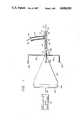
- the inventionincludes a catheter 11 that defines a passageway 19 for flow of fluids --liquids, gases, or both. Such fluids flow into or out of the body of a patient, as suggested by the bidirectional arrow at 17. It will be understood that the portion 11 of the catheter appearing in FIG. 1 is distal with respect to the patient's body. For purposes of illustrating the portion of the invention that is outside the patient's body, the illustration of the catheter is interrupted at 12.
- the distal portion 11 of the catheterhas a hose fitting 13 for attachment of a supply or drain tube 15, which similarly defines a flow path as suggested by the arrow at 18 between the passageway 19 and a source of--or a drain for--the fluids of interest.
- a supply or drain tube 15which similarly defines a flow path as suggested by the arrow at 18 between the passageway 19 and a source of--or a drain for--the fluids of interest.
- sources and drainsare well known in the art, neither is illustrated, the drawing of the supply or drain tube 15 being simply interrupted at 16.
- FIG. 1further includes a special vibration-transmitting fitting 14.
- This fitting 14may be integral with the catheter 11 and aligned with the body of the catheter 11 as shown, while the fluid supply or drain tube 15 is disposed at an angle to both. In this way the vibration-transmitting fitting 14 can project vibration axially into the material of the catheter wall 11 and into the passageway 19, from a source to be described.
- the fitting 14need not be integral with, but may instead be attached to, the catheter 11--as will be clear from the following discussion.
- the FIG. 1 embodiment of our inventionalso has vibration source and transmission devices. These include a frequency-controllable electrical oscillator and amplifier 21, electrical leads 22 conveying amplified electrical oscillations or to a piezoelectric or other transducer 23, a vibration receiver/transmitter plate 24 firmly secured to the transducer, a solid horn 25 firmly secured to or integral with the plate 24, an attachment receptacle 26 formed in the end of the horn 25 opposite the plate 24, and a solid rod 31-32-33 for transmitting vibration from the horn 25 to the previously mentioned fitting 14.
- vibration source and transmission devicesinclude a frequency-controllable electrical oscillator and amplifier 21, electrical leads 22 conveying amplified electrical oscillations or to a piezoelectric or other transducer 23, a vibration receiver/transmitter plate 24 firmly secured to the transducer, a solid horn 25 firmly secured to or integral with the plate 24, an attachment receptacle 26 formed in the end of the horn 25 opposite the plate 24, and a solid rod 31-32-33 for
- the source components 21, 22, 23, 24, 25 and 26, and the distal part 31 of the rod 31-32-33 when in use,may be housed in a suitable enclosure 27--shown interrupted at 28 for convenience of illustration.
- the enclosure 27advantageously has an aperture 29 for passage of the rod 31 into the receptacle 26. Electrical power may be supplied through the enclosure 27 to the oscillator and amplifier 21 by a conventional power connection (not illustrated).
- the proximal portion 32-33 of the transmitting rod 31-32-33is configured to firmly mate with and engage the transmitting fitting 14, as illustrated by the male-female interconnection in the drawing.
- the male and female portions 33 and 14 of the engagementare advantageously threaded together or otherwise fastened, to secure the engagement against separation during transmission of mechanical vibration from the source components into the catheter 11.
- the vibration-transmitting distal portion 31 of the rod 31-32-33is advantageously continuous with the proximal portion 32-33, the illustrated gap at 34 being merely for purposes of suggesting an intervening rod length of indefinite extent.
- the source components 21 through 27may be separated from the catheter 11 at the patient's bedside by many rooms, and may even be on separate floors, in a medical facility with centralized source components; or alternatively the source components 21 through 27 may be disposed at the immediate site of use. If the distance is relatively long, the material and the configuration of the rod 31-32 are preferably chosen for minimal attenuation per unit length of the rod 31-32, so that effective amplitude remains at the fitting 14 for cleaning action within the catheter 11. Alternatively, or in addition, a booster/repeater can be used.
- the fluids to be passed through the catheterare liquids, then they may be the primary medium for transmission of vibration along the catheter 11 from the transmitting fitting 14. If the fluids of interest are gaseous, then they may not be capable of supporting sufficient power transmission for effective cleaning action. In that case, either the material and structure of the catheter wall 11 must be selected for suitable vibration-transmitting properties or one of the other forms of our invention must be employed.
- the catheter distal portion 11 of FIG. 1may be continued as illustrated in FIG. 2 into a distal portion 11, intermediate portion 41, and proximal portions 41a and 43.
- the portion 11 of FIG. 1is continuous with the distal portion 11 of FIG. 2.
- An interruption of essentially indefinite lengthis shown at 42, followed by the proximal portion 41-43 of the catheter. It is this latter portion that passes within the body of the patient, defining a passageway 49 that communicates with the passageway 19 of the distal portion 11.
- the proximal portion 41-43 of the cathetermay have a sheath 46 that absorbs vibration--to prevent harmful radial propagation of vibration into the patient's tissues surrounding the catheter.
- the sheath 46may be continued into an elongated tip 47, to similarly prevent harmful axial propagation of vibration from the proximal end of the catheter. In this way the patient may be protected from the vibration projected into the catheter 11-41-43 by the fitting 14 (FIG. 1). If the fluids to be passed through the catheter are gases, the walls 11-41-41a-43 of the catheter may be made of vibration-transmitting material.
- the tube 11-41-41a-43In order to function as a catheter, the tube 11-41-41a-43 must have some proximal opening or openings for inward or outward flow of fluid.
- the form of the invention shown in FIG. 2has a multiplicity of radial orifices 44, 45. These orifices may be axially aligned in sets as at 44, or may be offset as at 45. (It will be understood that in any given catheter for particular applications, either all the orifices may be axially aligned as at 44, or all may be offset as at 45. For still other purposes it may be preferred to have some orifices aligned and some offset.)
- the sheath 46may be cut away as in generally conical configurations at 48 to minimize any tendency of the sheath to support accretion of undesirable substances where the vibrational energy density is greatly reduced just outside the orifices 44, 45. It is also important, however, to avoid excessive leakage of the vibration into the patient's body at these very points.
- the best configuration of the radially outward portions of the catheter wall 41a and of the sheath 46 adjacent the orifices 44, 45thus will depend upon the balance between avoiding excessive accumulation of undesirable substances and avoiding excessive vibration leakage. This tradeoff may be effectuated in a straightforward fashion in light of the principles described in this document, and based on collection of operational data from prototypes in ordinary ways. This tradeoff will vary strongly with proximity of the catheter to various types of tissues in the body.
- the amount of vibrational energy that is required --and the amount that is permitted--at the orifices 44, 45 of the catheter wall proper 41awill vary with several factors, such as the type of fluid that is to flow through the catheter, the type of body tissue which surrounds the intermediate portion 41 of the catheter, the portion of the patient's body into which the proximal part of the catheter extends, and perhaps most importantly the types and severity of undesirable substance that may be anticipated. These same factors accordingly must guide the routine design of apparatus according to our invention, to effectuate the tradeoff discussed above.
- the conical contours 48 of FIG. 2may be replaced by other configurations such as suggested in FIG. 3. (It will be understood that in a typical circumstance either the configuration 48a or the configuration 48b-48c may be used, rather than both in a single catheter.)
- One configuration appropriate for intermediate-to-high energy, or intermediate-to-high danger from vibration leakage,may be a raised crater-like guard rim 48a, formed in the sheath 46a surrounding each orifice 44a, but spaced radially (relative to the axis of the orifice) outward.
- an appropriate configurationmay be a secondary aperture 48c that is formed in the sheath 46b and that defines with the wall 41a disc-shaped trap chamber 48b.
- This trap chamber 48bmay be sized in diameter or depth to resonate at a nominal center frequency of the mechanical vibration--or, alternatively, the vibration can be periodically adjusted to a frequency at which the chamber 48b resonates --to help keep the structure 48b-48c free of obstructions while minimizing radiation at the secondary aperture 48c.
- Precise proportions and contours of the raised guard 48a or trap 48b-48c, relative to the diameter of the catheter wall 41a and the sheath 46a proper,will also depend upon the particular application for which a catheter is intended. In some cases a sheath 46 may be unnecessary, but guards 48a or traps 48b-48c may be formed integrally with or attached individually to the catheter wall 41a proper adjacent to each orifice or adjacent to particular orifices where radiation is of particular concern.
- FIG. 4shows a preferred embodiment of our invention that has a catheter with separate supply and drain tubes 115, 115', and that uses a solid fiber 132 for transmitting vibration to the proximal orifices of the catheter.
- the source components 121 through 131are essentially the same as the correspondingly numbered elements in FIG. 1, except that in FIG. 4 the prefix "1" has been inserted before each reference numeral; and except that in FIG. 4 the electrical leads 122 are shown as being of indefinite length and having a repetitively removable plug 122a that mates with a receptacle 121a at the output of the oscillator and amplifier 121.
- FIG. 4may be conceptualized either as (1) a central oscillator and amplifier 121, with electrical transmission lines 122 running to individual transducers 123/124 at the patient's location--or (2) a central oscillator, amplifier and transducer 121-124, with mechanical vibration transmission lines 131-132 running to individual catheters at the patient's location, more in the fashion of FIG. 1.
- a central oscillator and amplifier 121with electrical transmission lines 122 running to individual transducers 123/124 at the patient's location--or
- a central oscillator, amplifier and transducer 121-124with mechanical vibration transmission lines 131-132 running to individual catheters at the patient's location, more in the fashion of FIG. 1.
- the same alternativesare available with respect to the FIG. 1 embodiment.
- FIG. 4 embodimentis shown with the catheter 111 truncated at 112, and the input tube 115 and output tube 115' are likewise truncated at 116 and 116' respectively.
- Fluidssuch as air or other gases, or liquids, or both, may flow into the patient's body, as indicated by flow arrow 118, through a passageway 119 defined in the input tube 115; and may flow out of the patient's body, as indicated by arrow 118', through a passageway 119' defined in the output tube 115'.
- the vibration produced in the transducer 123/124is concentrated at 125 and then conducted by a plastic, glass, or quartz fiber 132 to the proximal orifices of the catheter 111.
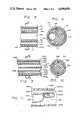
- FIGS. 5 and 6show the intermediate portions of the FIG. 4 catheter 111, the longitudinal section of FIG. 5 being more schematic.
- FIG. 5there may be seen the generally cylindrical exterior surface of the vibration-transmitting fiber 132, the generally cylindrical interior surfaces of the passageways 119 and 119', and in longitudinal section the materials 151, 153 of the catheter 111.
- FIG. 6there appear in cross-section the fiber 132 and the materials 151, 153 of the catheter 111; and as open cavities the lumens 119, 119'.
- the catheter 111may have a separate sheath 151 and a body material 153 in which the lumens 119 and 119' are formed and the transmitting fiber 132 is embedded.
- This sheath 151may be provided as a separate element for certain purposes that will become clear in connection with the later discussion of FIG. 7.
- the sheath 151may be provided as a separate element purely for structural reasons, if it is desired to impart strength, slipperiness or other properties to the outer surface that are not desired in the inner body 153.
- the vibration conducted along the fiber 132will be sufficiently well confined to the fiber itself--with respect to propagation radially from the wall of the fiber--as to obviate the need for a sheath of the vibration-absorbing type as indicated in FIG. 1.
- the cathetermay have no separate sheath 151, and the body material 153 may simply be enlarged to encompass the portions shown separately as 151 in FIGS. 5 and 6.
- the fibermay be replaced by a vibration-transmitting liquid sealed in a lumen of the catheter.
- a vibration-absorbing sheathas discussed in connection with FIGS. 2 and 3 may be desirable, or the vibration-transmitting lumen may be disposed more centrally in the catheter body 153 and the body 153 made of vibration-absorbing material.
- FIG. 6Also shown in FIG. 6 are other optional lumens 132', defined in the body material 153, that may be used for any number of other purposes such as pressure measurement, insertion of microminiaturized viewing apparatus, and so forth. In some instances the operation of our invention may facilitate these other purposes.
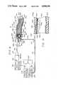
- FIG. 7shows the proximal end of the catheter of FIGS. 4 through 6.
- the outer sheath 151may be convoluted to form annular gas-diffusion bags or balloons 157.
- the volume 159 enclosed within these annular bags 157communicates with the input passageway 119, and the material of the balloons 157 may be semipermeable so as to permit supply of oxygen or other therapeutic gas into a particular region within the patient's body.
- the proximal end of the sheathmay be formed, as illustrated, into a somewhat elongated tip 158 for absorption of radially projected vibration (though vibration will typically be confined by the intrinsic operation of the transmitting fiber 132); or may be shaped to facilitate insertion of the catheter.
- the inner enclosure 153that forms the extension of the body material 153 of FIGS. 5 and 6.
- This inner enclosure 153is for the purpose of conducting waste fluids away from a site within the patient's body, collecting such waste fluids through orifices 156a and 156b.
- These orificesmay either open into the gas-diffusion balloons, or pass through the outer shield 157 and open directly into the patient's body (or some orifices may do one and some the other) as appropriate to the patient's circumstances and the therapy in use.
- orificesthere may be multiple orifices, rather than only two as illustrated.
- the orificesmay be oval with the long dimension of each orifice paralleling the axis of the catheter, as illustrated.
- the orificesmay have any number of other shapes or orientations as found appropriate for the particular application and the particular vibrational frequencies, power levels, and propagational modes in use.
- the vibration-transmitting fiber 132is bifurcated as at 154 and its two tips pass into the wall 153 of the inner chamber, and embedded in this wall they proceed directly to terminations 155a and 155b adjacent to the two orifices 156a and 156b respectively.
- the terminationsare drawn in solid lines, although it is to be understood that the tips and terminations 155a, 155b are actually embedded in the wall adjacent the orifices 156a, 156b.
- the fiber 132may more likely have multiple endings passing to multiple orifices respectively.
- the terminations 155a and 155bmay be broadened tips, as shown, of the fibers 154a and 154b--to more effectively broadcast the vibrational energy into the entire space defined by each orifice. These tips may be disposed adjacent a short dimension of the periphery of each orifice, as at 155a, or adjacent a long dimension as at 155b,depending upon the frequencies to be used, the types of undesirable substance anticipated, and so forth.
- FIG. 8represents a more highly preferred embodiment of our invention, in which feedback information reflecting the efficacy of the vibrational cleansing is used to optimize that efficacy.
- FIG. 8that have reference numerals similar (with the prefix "2") to the numerals in FIGS. 1 through 7 correspond to the features in those earlier drawings.
- vibrationis transmitted along a fiber 232, as suggested by the arrow at 261, through the catheter 211 into the patient's body; while fluids proceed via passageway 219 into the patient's body as indicated by the arrow at 218, and fluids leave the patient's body via passageway 219' as indicated by the arrow at 218'.
- FIG. 8there is within the catheter 211 a vibration-sensor feedback fiber 272.
- This feedback fiber 272carries unabsorbed vibration from the proximal end of the catheter as suggested by the arrows 277 back to the distal end 272, and thence along a similar fiber 272a, 271 to a vibration sensor 273.
- the vibrationis advantageously made to generate an electrical signal 278 related to the amplitude of the vibration received at the sensor 273.
- the sensor 273may be any of various forms of vibration sensor.
- the sensormay include a piezoelectric crystal driving a high-impedance preamplifier or FET electrometer. Such devices may not be fast enough to follow the vibration cycle as such, but they may be able to detect rectified signals from the crystal and thereby provide a measure of vibration amplitude.
- the senor 273may comprise an optical system which geometrically amplifies the mechanical displacement at the distal end of the fiber 271--as by directing a light beam onto the polished fiber tip at an angle and detecting the displacement amplitude of the reflected beam.
- the sensor 273may incorporate an interferometric system: a laser beam may be reflected from the fiber tip, and the system made to count the number of resulting optical fringes that pass a photodector per cycle of the mechanical vibration.
- the distal end of fiber 271may take the form of a very long coil.
- a half-silvered, angled surfacemay be formed along the fiber 271 and used to introduce a laser beam into the coiled portion of the fiber. Phase differences in the laser beam due to the periodic elongation of the fiber coil may be detected at the distal tip of the fiber. It will be understood that these examples are merely exemplary and not intended to be exhaustive.
- An electrical signal 278 from the vibration sensoris received in the automatic frequency-control block 275, which produces a frequency-varying feedback signal 281 for passage to the oscillator and amplifier 221, as suggested by the arrow at 282.
- This signal 281may simply act to maintain maximum absorption of vibration at the proximal end of the catheter 211.
- the automatic frequency control 275may be programmed to force the vibration frequency to "dwell" at plural or multiple values that correspond to local maxima in the vibration-absorption spectrum of the substances at proximal end of the catheter.
- Known techniques of electronics and mechanicsmay be used to change the frequency or amplitude, or to sweep or skip frequencies, or to provide pulses (rather than continuous vibrations) of various frequencies and amplitudes, and so forth.
- the automatic frequency control 275may also be programmed to cause the vibration frequency to dwell at one or more predetermined values that are known to correspond to acoustic resonances within, or wall resonances of, the vibration guard or trap structures 48a, 48b, 48c (FIG. 3). The purpose of this provision is to help keep the guard or trap structures clear.
- the frequency control 275may require separate programming for this purpose since, due to the resonance, the feedback system 272-281 may report these frequencies as corresponding to absorption minima.
- connector block 262also appears in FIG. 8.
- the blockhas nipples 268 that fit tightly into the passageways 219, 219' at the distal end 272 of the catheter 211.
- Passageways 269 in the block 262provide communication between the supply passageway 219 in the catheter 211 and a supply hose 215, and between the drain passageway 219' and a drain hose 215'.
- the blockalso has nipples 265 that fit tightly into the lumens of these hoses 215, 215'.
- the block 262effectively secures the catheter 211 and hoses 215, 215' together with their corresponding passageways in communication.
- the blockhas apertures 263, 267 for free passage of the vibration-transmitting fibers 232, 272. These apertures may be used as convenient protective locations for lightweight, vibration-transmitting couplings 264, 266 that provide continuity of the cleaning-vibration transmitting fibers 232, 232a and continuity of the feedback-vibration transmitting fibers 272, 272a, respectively.
- the transmission fiberseither are cemented into their respective couplings 264, 266 or are press-fit or threaded together so that the catheter can be repetitively disconnected from and reconnected to the block 262.
- the proximal end of the connector 264 and the exposed distal tip of the fiber 232 in the catheter 211can be threaded together with one handedness of thread
- the distal end of the connector 264 and the proximal tip of the fiber 232a that carries vibration from the horn 225can be threaded together with the opposite handedness of thread.
- the connector 264can be rotated in one direction to screw it onto the tips of both fibers 232 and 232a simultaneously, or rotated in the other direction to unscrew it from both fibers simultaneously.
- the intermediate structure of the catheteris similar to that of FIGS. 5 and 6, with the addition of the vibration-sensor feedback fiber 232'.
- the feedback fiber 232is embedded within the body material 253 of the catheter.
- FIG. 11shows one of many possible arrangements of the proximal tips 255, 257 of the fibers 254 (232 in the earlier drawings) and 232'.
- the walls 253 of the lumen 219appear at the top and bottom of the drawing.
- An outer sheath or gas-diffusion balloonsmay also be provided as in FIG. 7, but for simplicity of the drawing they are not shown in FIG. 11. If not required for the application at hand, the outer sheath or balloons may be omitted; thus the drawing in FIG. 11 should be understood to represent either one lumen of a bidirectional catheter or the single lumen of a supply or drain catheter.
- FIG. 11a small accretion of undesirable substance 291 is represented in FIG. 11. It will be understood that in continuous operation of our invention such accumulations will be minimal or nonexistent; however, in certain cases for various therapeutic reasons that may arise the vibration source may not be operated continuously. Hence small deposits 291 may develop while the source is turned off.
- the cleaning-vibration fiber 254is embedded in the catheter wall adjacent to a supply or drain orifice 256, as described in connection with FIG. 7.
- the termination 257 of the feedback fiber 232'is similarly embedded within the catheter wall, diametrically across the supply or drain orifice 256 from the termination 255 of the cleansing-vibration fiber 254.
- the geometry of the orifice 256 and of the fiber terminations 255 and 257can vary widely.
- Vibration from the input-fiber termination 255 that is not absorbed in disintegration of undesirable substances 291 within the orifice 256is transmitted across the orifice 256 via liquids within the orifice to the feedback-fiber termination 257.
- the termination 257absorbs some of this unused vibrational energy and transmits it back along fiber 232' to the sensor 273, for use as previously described.
- the relative configuration of the transmitting and receiving terminations 255 and 257 respectivelymay take various forms.
- the two terminationsmay be adjacent one another on a common side of the orifice 256, with a vibration reflector disposed at the opposite side, if such a configuration is found particularly effective.
- Such a reflection systemmight be desirable, for example, to generate an absorption measurement that is representative of phenomena just outside the orifice--i.e., just beyond the catheter wall--as well as immediately within the orifice 256.
- FIG. 12illustrates a configuration of transmitting and receiving terminations 455 and 457 that is more specifically designed to be sensitive to measurement of vibration outside the catheter wall.
- this configurationis particularly directed to the monitoring of vibration leakage, although it may also be useful under some circumstances to monitor absorption for the purposes discussed above in connection with FIGS. 8 through 11.
- the system of FIG. 12is contemplated for use in generating an alarm signal--or in shutting down or lowering the amplitude of the vibration automatically--if the vibration levels outside the catheter are high enough to pose a threat to the patient's body tissues.
- the transmitting termination 455is disposed within the catheter wall.
- This termination 455points into the orifice 456, to project vibration toward deposits on the surfaces of the orifice or toward bacteria or large particles suspended in the fluid within the orifice--and even within the lumen 419'. (Under some circumstances it may be preferred to instead position the transmitting termination 455 inside the lumen 419', to better isolate the vibration from the patient's tissues.)
- the receiving termination 457is positioned outside the orifice, in the external wall of the catheter, in a region PG,36 where the vibration level tends to be correlated with the vibration level actually reaching the patient's body tissues.
- the termination 457may be closer to or farther from the orifice 456, or may point toward or away from the orifice, or may point at various angles radially outward from the catheter external surface.
- the optimum precise positioning and orientationmust be determined for each application, taking into account how delicate the particular tissues are, and how close to the catheter tip those tissues are, in the part of the body where the catheter tip will be.
- Duration of the expected exposureshould also be taken into account in selecting the received vibration amplitude at which the alarm or automatic vibration-control system is triggered.
- liquid being supplied or drained through the catheter of our inventionmay serve as the conducting medium for conveyance of vibration to the catheter orifices.
- such liquidmay be regarded as unsuited to the vibration-transmitting function.
- the dynamic properties of a liquid being drained from the patient's bodymay be found to vary unpredictably with both the concentration and the type of particulate inclusions in the drain liquid.
- medicinal or nutritive properties of certain fluids being supplied to the patient's bodymay deteriorate under the influence of the transmitted vibration. Likewise gaseous fluids in most situations will be unsuited for supporting effective vibrational power transmission.
- FIGS. 13 through 15illustrate a form of our invention that uses such nonsolid conveying means.
- the catheter used in this embodiment of our inventionhas a supply or drain lumen 719 for flow of fluids in or out of the patient's body as suggested by the two-headed arrows 717, 718.
- the catheteralso has an auxiliary lumen (or lumens) containing a liquid 732 which is not drained from or supplied into the patient's body tissues or cavities. Rather this liquid 732 is present for the particular purpose of conducting vibration from a converter 723 (FIG. 15) to the regions adjacent the several proximal orifices 756, 756a-756d. Vibration transmission through the fluid 732 is represented by the arrows 761.
- auxiliary lumen illustrated in FIGS. 13 through 15is annular, being formed as a space between an external, generally cylindrical wall 751 and an internal, generally cylindrical wall 753. If preferred the auxiliary lumen (or lumens) need not be annular but may simply parallel the supply or drain lumen 719.
- the fluidmay be sealed statically within the auxiliary lumen, or if desirable it may be circulated through the auxiliary lumen by dividing the auxiliary lumen into two or more generally longitudinal channels and using one or more of these channels for liquid flow in each direction.
- FIGS. 13 through 15may be interpreted as representing either arrangement, since generally longitudinal dividing walls could be disposed along the catheter out of the plane of the drawings in FIGS. 13 and 15.)
- the liquid in certain channelswould be moving in opposite directions, vibration could nevertheless be conducted in the distal-to-proximal direction through the moving fluid in all the channels.
- Orifices 756, 756a-756dpass through the annular auxiliary lumen containing the liquid 732, but with respect to fluid communication they are isolated from the annular auxiliary lumen by the orifice walls 755. These walls 755 do, however, receive the vibration 761 through the liquid 732 and serve to transmit this vibration into the orifices 756, 756a-756d.
- the orificesmay be tapered at one end or the other as at 756b and 756d, or they may have outwardly projecting vibration-guard contours (discussed earlier) as at 756c, or both. Alternatively they may be simple cylindrical shapes as at 756a, and so forth.
- the form of our invention illustrated in FIGS. 13 through 15does not necessarily incorporate any vibration-sensor feedback feature.
- the auxiliary lumenmay be divided into a number (perhaps ideally an even number) of generally parallel auxiliary lumens by longitudinal walls which intersect the orifice walls 755. Every other auxiliary lumen around the periphery of the annulus may then be used for transmitting vibration to all the orifice walls 755, and the alternate lumens may be used for receiving vibration from the diametrical walls of the same orifices.
- the auxiliary lumensmay all be straight and essentially parallel to the supply or drain lumen 719, with the orifices therefore all aligned in corresponding straight parallel rows along the outer surface of the catheter. (Once again FIGS. 13 through 15 may be interpreted as illustrating either a system with or without discrete plural lumens.) If preferred, however, and if practical to construct, the auxiliary lumens may spiral or meander in any other pattern, provided only that the orifices are positioned along the walls that separate the plural auxiliary lumens.
- auxiliary lumens for circulation of the vibration-conducting liquidis compatible with the use of plural auxiliary lumens for provision of a vibration-sensing feedback system. That is, both liquid circulation and vibration-sensing feedback may be provided using the same set of two or more lumens.
- vibration-conductive pathsmay be provided for different regions along the length of the catheter, and correspondingly different vibration-sensor feedback paths may likewise be provided.
- Data acquisition of this discriminating typemakes it possible to direct to each group of orifices only vibration at frequencies appropriate to the accretions in those particular orifices.
- the source components mentioned earlier, as well as the vibration sensor feedback systemmay be time-shared between the separate conductive paths.
- each set of conductive pathsmay be provided with its own correspondingly separate source components (oscillator and amplifier, and converter), and a correspondingly separate set of vibration-sensor and automatic frequency-control modules. Using this approach each different group of orifices may receive vibration appropriate to its own accretions continuously, though at increased cost.
- the ultrasound waves or other mechanical vibrationsmay be conducted through liquids, plastics such as nylon, metals or other materials.
- a preferred conduitis a quartz fiber, one to two millimeters in diameter and of length varying with the length of the tube.
- shear wavesare preferred since they can be more effectively controlled at the proximal orifices of a catheter and--due to their rapid attenuation outside the catheter--they should be more effective in breaking up solid material or bacteria at the orifices without injuring adjacent body tissue.
- the shear wavesmay be polarized either horizontally or vertically, though we believe that horizontal polarization is preferable to minimize radiation into adjoining tissues of the host.
- the vibrationmay be either continuous wave ("CW"), or pulsed or periodic.
- Ultrasound and other vibrational frequenciescan be varied and easily controlled to "match" the size of certain selected bacteria or other particles. By obtaining such resonances the bacteria can be killed, and bacteria or other particles destroyed, selectively on the basis of mass and shape. This fact has enormous implications for the success of our invention, since it means that the cleansing mechanism can follow the bacteria through at least any imaginable kinds of mutation and structure.
- our inventionmay be best implemented by providing a centrally located transducer that transmits vibration through fibers to a connector at each bed. Attendants thus would plug each catheter into a vibration-source connector just as they plug other equipment into electrical-source connectors. Alternatively an individual transducer can be used for each individual catheter.
- the catheters themselvesmay be either disposable or reusable.
Landscapes
- Health & Medical Sciences (AREA)
- Life Sciences & Earth Sciences (AREA)
- Biophysics (AREA)
- Pulmonology (AREA)
- Engineering & Computer Science (AREA)
- Anesthesiology (AREA)
- Biomedical Technology (AREA)
- Heart & Thoracic Surgery (AREA)
- Hematology (AREA)
- Animal Behavior & Ethology (AREA)
- General Health & Medical Sciences (AREA)
- Public Health (AREA)
- Veterinary Medicine (AREA)
- Epidemiology (AREA)
- Urology & Nephrology (AREA)
- Media Introduction/Drainage Providing Device (AREA)
Abstract
Description
Claims (25)
Priority Applications (10)
| Application Number | Priority Date | Filing Date | Title |
|---|---|---|---|
| US06/787,728US4698058A (en) | 1985-10-15 | 1985-10-15 | Ultrasonic self-cleaning catheter system for indwelling drains and medication supply |
| JP61505577AJP2534047B2 (en) | 1985-10-15 | 1986-10-14 | Ultrasonic self-cleaning catheter system with drainage and dosing functions |
| PCT/US1986/002170WO1987002255A1 (en) | 1985-10-15 | 1986-10-14 | Ultrasonic self-cleaning catheter system |
| DE3689617TDE3689617T2 (en) | 1985-10-15 | 1986-10-14 | ULTRASONIC SELF-CLEANING CATHETER SYSTEM. |
| AU65227/86AAU6522786A (en) | 1985-10-15 | 1986-10-14 | Ultrasonic self-cleaning catheter system |
| AT86906615TATE101053T1 (en) | 1985-10-15 | 1986-10-14 | ULTRASONIC SELF-CLEANING CATHETER SYSTEM. |
| EP86906615AEP0243458B1 (en) | 1985-10-15 | 1986-10-14 | Ultrasonic self-cleaning catheter system |
| US07/096,068US4906238A (en) | 1985-10-15 | 1987-09-14 | Exterior antimigration refinements for self-cleaning indwelling therapeutic articles |
| US07/485,966US5061255A (en) | 1985-10-15 | 1990-02-27 | Exterior antimigration refinements for self-cleaning indwelling therapeutic articles |
| US07/783,844US5271735A (en) | 1985-10-15 | 1991-10-29 | Exterior antimigration refinements for self-cleaning indwelling therapeutic articles |
Applications Claiming Priority (1)
| Application Number | Priority Date | Filing Date | Title |
|---|---|---|---|
| US06/787,728US4698058A (en) | 1985-10-15 | 1985-10-15 | Ultrasonic self-cleaning catheter system for indwelling drains and medication supply |
Related Child Applications (1)
| Application Number | Title | Priority Date | Filing Date |
|---|---|---|---|
| US07/096,068Continuation-In-PartUS4906238A (en) | 1985-10-15 | 1987-09-14 | Exterior antimigration refinements for self-cleaning indwelling therapeutic articles |
Publications (1)
| Publication Number | Publication Date |
|---|---|
| US4698058Atrue US4698058A (en) | 1987-10-06 |
Family
ID=25142371
Family Applications (1)
| Application Number | Title | Priority Date | Filing Date |
|---|---|---|---|
| US06/787,728Expired - LifetimeUS4698058A (en) | 1985-10-15 | 1985-10-15 | Ultrasonic self-cleaning catheter system for indwelling drains and medication supply |
Country Status (6)
| Country | Link |
|---|---|
| US (1) | US4698058A (en) |
| EP (1) | EP0243458B1 (en) |
| JP (1) | JP2534047B2 (en) |
| AU (1) | AU6522786A (en) |
| DE (1) | DE3689617T2 (en) |
| WO (1) | WO1987002255A1 (en) |
Cited By (116)
| Publication number | Priority date | Publication date | Assignee | Title |
|---|---|---|---|---|
| US4836211A (en)* | 1986-09-17 | 1989-06-06 | Naomi Sekino | Ultrasonic treatment apparatus for performing medical treatment by use of ultrasonic vibrations |
| US4870953A (en)* | 1987-11-13 | 1989-10-03 | Donmicheal T Anthony | Intravascular ultrasonic catheter/probe and method for treating intravascular blockage |
| US4906238A (en)* | 1985-10-15 | 1990-03-06 | Albert R. Greenfeld | Exterior antimigration refinements for self-cleaning indwelling therapeutic articles |
| WO1990001971A1 (en)* | 1988-08-18 | 1990-03-08 | Massachusetts Institute Of Technology | Ultrasound enhancement of transbuccal drug delivery |
| US4942868A (en)* | 1988-03-30 | 1990-07-24 | Malmros Holding, Inc. | Ultrasonic treatment of animals |
| US5061255A (en)* | 1985-10-15 | 1991-10-29 | Albert Greenfeld | Exterior antimigration refinements for self-cleaning indwelling therapeutic articles |
| US5069664A (en)* | 1990-01-25 | 1991-12-03 | Inter Therapy, Inc. | Intravascular ultrasonic angioplasty probe |
| US5197946A (en)* | 1990-06-27 | 1993-03-30 | Shunro Tachibana | Injection instrument with ultrasonic oscillating element |
| US5267985A (en)* | 1993-02-11 | 1993-12-07 | Trancell, Inc. | Drug delivery by multiple frequency phonophoresis |
| US5282785A (en)* | 1990-06-15 | 1994-02-01 | Cortrak Medical, Inc. | Drug delivery apparatus and method |
| US5344395A (en)* | 1989-11-13 | 1994-09-06 | Scimed Life Systems, Inc. | Apparatus for intravascular cavitation or delivery of low frequency mechanical energy |
| US5369831A (en)* | 1991-03-25 | 1994-12-06 | Sonex International Corporation | Therapeutic ultrasonic toothbrush |
| US5423764A (en)* | 1993-06-14 | 1995-06-13 | Fry; William A. | Lavage apparatus |
| US5458568A (en)* | 1991-05-24 | 1995-10-17 | Cortrak Medical, Inc. | Porous balloon for selective dilatation and drug delivery |
| US5498238A (en)* | 1990-06-15 | 1996-03-12 | Cortrak Medical, Inc. | Simultaneous angioplasty and phoretic drug delivery |
| US5609606A (en)* | 1993-02-05 | 1997-03-11 | Joe W. & Dorothy Dorsett Brown Foundation | Ultrasonic angioplasty balloon catheter |
| US5665141A (en)* | 1988-03-30 | 1997-09-09 | Arjo Hospital Equipment Ab | Ultrasonic treatment process |
| US5725494A (en)* | 1995-11-30 | 1998-03-10 | Pharmasonics, Inc. | Apparatus and methods for ultrasonically enhanced intraluminal therapy |
| US5725570A (en)* | 1992-03-31 | 1998-03-10 | Boston Scientific Corporation | Tubular medical endoprostheses |
| US5728062A (en)* | 1995-11-30 | 1998-03-17 | Pharmasonics, Inc. | Apparatus and methods for vibratory intraluminal therapy employing magnetostrictive transducers |
| US5735811A (en)* | 1995-11-30 | 1998-04-07 | Pharmasonics, Inc. | Apparatus and methods for ultrasonically enhanced fluid delivery |
| US5807306A (en)* | 1992-11-09 | 1998-09-15 | Cortrak Medical, Inc. | Polymer matrix drug delivery apparatus |
| US5814599A (en)* | 1995-08-04 | 1998-09-29 | Massachusetts Insitiute Of Technology | Transdermal delivery of encapsulated drugs |
| US5846218A (en)* | 1996-09-05 | 1998-12-08 | Pharmasonics, Inc. | Balloon catheters having ultrasonically driven interface surfaces and methods for their use |
| US5931805A (en)* | 1997-06-02 | 1999-08-03 | Pharmasonics, Inc. | Catheters comprising bending transducers and methods for their use |
| US5947921A (en)* | 1995-12-18 | 1999-09-07 | Massachusetts Institute Of Technology | Chemical and physical enhancers and ultrasound for transdermal drug delivery |
| US6002961A (en)* | 1995-07-25 | 1999-12-14 | Massachusetts Institute Of Technology | Transdermal protein delivery using low-frequency sonophoresis |
| US6041253A (en)* | 1995-12-18 | 2000-03-21 | Massachusetts Institute Of Technology | Effect of electric field and ultrasound for transdermal drug delivery |
| US6135976A (en)* | 1998-09-25 | 2000-10-24 | Ekos Corporation | Method, device and kit for performing gene therapy |
| US6183450B1 (en) | 1999-06-04 | 2001-02-06 | William A Lois | Catheter de-clogging device |
| US6221038B1 (en) | 1996-11-27 | 2001-04-24 | Pharmasonics, Inc. | Apparatus and methods for vibratory intraluminal therapy employing magnetostrictive transducers |
| US6228046B1 (en) | 1997-06-02 | 2001-05-08 | Pharmasonics, Inc. | Catheters comprising a plurality of oscillators and methods for their use |
| US6234990B1 (en) | 1996-06-28 | 2001-05-22 | Sontra Medical, Inc. | Ultrasound enhancement of transdermal transport |
| WO2001038105A1 (en)* | 1999-11-22 | 2001-05-31 | Laser- Und Medizin Technologie Ggmbh Berlin | Ultrasound glass fiber brush |
| US6277084B1 (en) | 1992-03-31 | 2001-08-21 | Boston Scientific Corporation | Ultrasonic medical device |
| US6416540B1 (en) | 2000-11-01 | 2002-07-09 | Sandip V. Mathur | Magnetically actuated cleanable stent and method |
| US6428491B1 (en)* | 1999-08-27 | 2002-08-06 | Dan Weiss | Delivery of ultrasound to percutaneous and intrabody devices |
| US6464660B2 (en) | 1996-09-05 | 2002-10-15 | Pharmasonics, Inc. | Balloon catheters having ultrasonically driven interface surfaces and methods for their use |
| US20030009125A1 (en)* | 1991-01-11 | 2003-01-09 | Henry Nita | Ultrasonic devices and methods for ablating and removing obstructive matter from anatomical passageways and blood vessels |
| US20030032899A1 (en)* | 2001-07-26 | 2003-02-13 | Matsushita Electric Works, Ltd. | Ultrasonic cosmetic device |
| US6524256B2 (en) | 2000-07-22 | 2003-02-25 | Biotronik Mess-und Therapiegeraete GmbH & Co. Ingenieürbuero Berlin | Implantable measuring device, particularly a pressure measuring device for determining the intracardial or intraluminal blood pressure |
| US6527802B1 (en) | 1993-01-19 | 2003-03-04 | Scimed Life Systems, Inc. | Clad composite stent |
| US20030216635A1 (en)* | 2000-01-06 | 2003-11-20 | Cohen Irun R | Method and system for monitoring pancreatic pathologies |
| WO2003099100A2 (en) | 2002-05-29 | 2003-12-04 | Nanovibronix, Inc. | Method, apparatus and system for treating biofilms associated with catheters |
| US6702761B1 (en) | 2000-03-06 | 2004-03-09 | Fonar Corporation | Vibration assisted needle device |
| US20040092956A1 (en)* | 2000-11-03 | 2004-05-13 | John Liddicoat | Catheter for removal of solids from surgical drains |
| US20040171980A1 (en)* | 1998-12-18 | 2004-09-02 | Sontra Medical, Inc. | Method and apparatus for enhancement of transdermal transport |
| US20040236268A1 (en)* | 1998-01-08 | 2004-11-25 | Sontra Medical, Inc. | Method and apparatus for enhancement of transdermal transport |
| US20040254522A1 (en)* | 2003-06-11 | 2004-12-16 | Kraus Robert G. | Needle guard having inherent probe directing features |
| WO2005058404A1 (en)* | 2003-12-17 | 2005-06-30 | Skansen Jan | Catheter device |
| US20050267421A1 (en)* | 2004-05-28 | 2005-12-01 | Wing Thomas W | Catheter cleaner |
| US20050268921A1 (en)* | 2004-05-18 | 2005-12-08 | Jona Zumeris | Nanovibration coating process for medical devices using multi vibration modes of a thin piezo element |
| WO2004093656A3 (en)* | 2003-04-22 | 2006-06-01 | Ekos Corp | Ultrasound enhanced central venous catheter |
| US7066884B2 (en) | 1998-01-08 | 2006-06-27 | Sontra Medical, Inc. | System, method, and device for non-invasive body fluid sampling and analysis |
| US7101392B2 (en) | 1992-03-31 | 2006-09-05 | Boston Scientific Corporation | Tubular medical endoprostheses |
| US20060235349A1 (en)* | 2005-04-14 | 2006-10-19 | Brett Osborn | Implantable anti-clogging device for maintenance of cerebrospinal fluid shunt patency |
| US20060258970A1 (en)* | 2005-04-29 | 2006-11-16 | Medtronic, Inc. | Anti-thrombogenic venous shunt system and method |
| US20060264988A1 (en)* | 2003-05-02 | 2006-11-23 | Metolius Biomedical, Llc | Body-space drainage-tube debris removal |
| US20070073239A1 (en)* | 2003-12-17 | 2007-03-29 | Jan Skansen | Catheter device |
| US20070173939A1 (en)* | 2005-12-23 | 2007-07-26 | The Board Of Trustees Of The Leland Stanford Junior University | Systems and methods for fixation of bone with an expandable device |
| WO2007110870A2 (en) | 2006-03-29 | 2007-10-04 | Nanovibronix Inc. | An acoustic add-on device for biofilm prevention in urinary catheter |
| US20070244423A1 (en)* | 2002-05-29 | 2007-10-18 | Jona Zumeris | Acoustic add-on device for biofilm prevention in urinary catheter |
| US20080082036A1 (en)* | 2006-04-25 | 2008-04-03 | Medtronic, Inc. | Cerebrospinal fluid shunt having long term anti-occlusion agent delivery |
| US20080154181A1 (en)* | 2006-05-05 | 2008-06-26 | Khanna Rohit K | Central nervous system ultrasonic drain |
| US7432069B2 (en) | 2005-12-05 | 2008-10-07 | Sontra Medical Corporation | Biocompatible chemically crosslinked hydrogels for glucose sensing |
| US20090264833A1 (en)* | 2008-01-25 | 2009-10-22 | Clear Catheter Systems, Llc | Methods and Devices to Clear Obstructions from Medical Tubes |
| US7818854B2 (en) | 2002-10-14 | 2010-10-26 | Ekos Corporation | Ultrasound radiating members for catheter |
| US20100318116A1 (en)* | 2008-01-28 | 2010-12-16 | Peter Forsell | drainage device comprising a filter cleaning device |
| US20110040286A1 (en)* | 2008-01-25 | 2011-02-17 | Clear Catheter Systems, Inc. | Methods and devices to clear obstructions from medical tubes |
| US7914509B2 (en) | 1997-05-01 | 2011-03-29 | Ekos Corporation | Ultrasound catheter |
| US20110106019A1 (en)* | 2007-11-21 | 2011-05-05 | Piezo Resonance Innovations, Inc. | Devices for clearing blockages in in-situ artificial lumens |
| US20110152790A1 (en)* | 2007-08-17 | 2011-06-23 | Searete Llc, A Limited Liability Corporation Of The State Of Delaware | Systems, devices, and methods including catheters having self-cleaning surfaces |
| US7976483B2 (en) | 1997-05-01 | 2011-07-12 | Ekos Corporation | Ultrasound assembly with increased efficacy |
| US20110208021A1 (en)* | 2008-12-04 | 2011-08-25 | Goodall Eleanor V | Systems, devices, and methods including implantable devices with anti-microbial properties |
| US20110208023A1 (en)* | 2008-12-04 | 2011-08-25 | Goodall Eleanor V | Systems, devices, and methods including implantable devices with anti-microbial properties |
| US20110213397A1 (en)* | 2010-02-26 | 2011-09-01 | Olivier Mathonnet | Frequency Shifting Multi Mode Ultrasonic Dissector |
| WO2011158244A3 (en)* | 2010-06-18 | 2012-02-09 | Technion Research & Development Foundation Ltd. | Self cleaning shunt |
| US8224414B2 (en) | 2004-10-28 | 2012-07-17 | Echo Therapeutics, Inc. | System and method for analyte sampling and analysis with hydrogel |
| US8226629B1 (en) | 2002-04-01 | 2012-07-24 | Ekos Corporation | Ultrasonic catheter power control |
| US8386027B2 (en) | 2007-04-27 | 2013-02-26 | Echo Therapeutics, Inc. | Skin permeation device for analyte sensing or transdermal drug delivery |
| US8647292B2 (en) | 2007-08-17 | 2014-02-11 | The Invention Science Fund I, Llc | Systems, devices, and methods including catheters having components that are actively controllable between two or more wettability states |
| US8702640B2 (en) | 2007-08-17 | 2014-04-22 | The Invention Science Fund I, Llc | System, devices, and methods including catheters configured to monitor and inhibit biofilm formation |
| US8734718B2 (en) | 2007-08-17 | 2014-05-27 | The Invention Science Fund I, Llc | Systems, devices, and methods including catheters having an actively controllable therapeutic agent delivery component |
| US8753304B2 (en) | 2007-08-17 | 2014-06-17 | The Invention Science Fund I, Llc | Systems, devices, and methods including catheters having acoustically actuatable waveguide components for delivering a sterilizing stimulus to a region proximate a surface of the catheter |
| WO2014116640A1 (en)* | 2013-01-22 | 2014-07-31 | Alcyone Lifesciences, Inc. | Systems and methods for shunting fluid |
| US8812071B2 (en) | 2007-03-07 | 2014-08-19 | Echo Therapeutics, Inc. | Transdermal analyte monitoring systems and methods for analyte detection |
| US20140276341A1 (en)* | 2013-03-14 | 2014-09-18 | DePuy Synthes Products, LLC | Detection and clearing of occlusions in catheters |
| US8888731B2 (en) | 2007-08-17 | 2014-11-18 | The Invention Science Fund I, Llc | Systems, devices, and methods including infection-fighting and monitoring shunts |
| US20150088090A1 (en)* | 2012-02-21 | 2015-03-26 | Hospi Corporation | Method and apparatus for a clog resistant orifice |
| US9005263B2 (en) | 2007-08-17 | 2015-04-14 | The Invention Science Fund I, Llc | System, devices, and methods including actively-controllable sterilizing excitation delivery implants |
| US20150290390A1 (en)* | 2012-11-21 | 2015-10-15 | Amgen Inc. | Drug delivery device |
| US9375223B2 (en) | 2009-10-06 | 2016-06-28 | Cardioprolific Inc. | Methods and devices for endovascular therapy |
| US9433764B2 (en) | 2014-04-18 | 2016-09-06 | Alcyone Lifesciences, Inc. | Systems and methods for shunting fluid |
| US9474831B2 (en) | 2008-12-04 | 2016-10-25 | Gearbox, Llc | Systems, devices, and methods including implantable devices with anti-microbial properties |
| WO2017070095A1 (en)* | 2015-10-19 | 2017-04-27 | The Trustees Of The University Of Pennsylvania | Apparatus and methods for improving catheter function |
| US10322230B2 (en) | 2016-06-09 | 2019-06-18 | C. R. Bard, Inc. | Systems and methods for correcting and preventing occlusion in a catheter |
| WO2019150369A1 (en)* | 2018-02-02 | 2019-08-08 | Microbot Medical Ltd. | Self-cleaning catheter systems with self-monitoring capabilities |
| US10391285B2 (en) | 2013-06-14 | 2019-08-27 | The Cleveland Clinic Foundation | Motion-assisted systems, devices and methods for minimizing obstruction of medical devices |
| US10471189B2 (en) | 2014-02-17 | 2019-11-12 | Clearflow, Inc. | Medical tube clearance device |
| EP3603720A1 (en)* | 2018-07-31 | 2020-02-05 | David Elsässer | Catheter desobstruction system |
| US10656025B2 (en) | 2015-06-10 | 2020-05-19 | Ekos Corporation | Ultrasound catheter |
| US10792480B2 (en) | 2016-10-13 | 2020-10-06 | Anuncia, Inc. | Shunt flushers and related methods |
| US20200345380A1 (en)* | 2016-12-22 | 2020-11-05 | C. R. Bard, Inc. | Ultrasonic endovascular catheter |
| US10926074B2 (en) | 2001-12-03 | 2021-02-23 | Ekos Corporation | Catheter with multiple ultrasound radiating members |
| US10974023B2 (en) | 2014-02-17 | 2021-04-13 | Clearflow, Inc. | Medical tube clearance |
| US11191886B2 (en) | 2013-06-14 | 2021-12-07 | The Cleveland Clinic Foundation | Motion-assisted systems, devices and methods for minimizing obstruction of medical devices |
| USD967407S1 (en) | 2021-04-16 | 2022-10-18 | Hollister Incorporated | Urinary catheter |
| USD967405S1 (en) | 2021-04-16 | 2022-10-18 | Hollister Incorporated | Urinary catheter |
| USD967406S1 (en) | 2021-04-16 | 2022-10-18 | Hollister Incorporated | Urinary catheter |
| USD967404S1 (en) | 2021-04-16 | 2022-10-18 | Hollister Incorporated | Urinary catheter |
| USD967403S1 (en) | 2021-04-16 | 2022-10-18 | Hollister Incorporated | Urinary catheter |
| US11491303B2 (en) | 2020-11-17 | 2022-11-08 | Clearflow, Inc. | Medical tube clearance device |
| US11672553B2 (en) | 2007-06-22 | 2023-06-13 | Ekos Corporation | Method and apparatus for treatment of intracranial hemorrhages |
| US11925367B2 (en) | 2007-01-08 | 2024-03-12 | Ekos Corporation | Power parameters for ultrasonic catheter |
| CN119792772A (en)* | 2025-03-11 | 2025-04-11 | 重庆沁影科技有限公司 | A drainage tube external fixator after breast cancer surgery |
| USD1083086S1 (en) | 2022-12-20 | 2025-07-08 | Hollister Incorporated | Intermittent urinary catheter |
Families Citing this family (8)
| Publication number | Priority date | Publication date | Assignee | Title |
|---|---|---|---|---|
| DE4432683C2 (en)* | 1994-09-14 | 1999-08-05 | Laser & Med Tech Gmbh | Method and device for cleaning a catheter or endoscope |
| US20080281250A1 (en)* | 2005-05-10 | 2008-11-13 | Marvin Bergsneider | Self-Clearing Catheter for Clinical Implantation |
| US8088091B2 (en) | 2009-03-09 | 2012-01-03 | New Jersey Institute Of Technology | No clog shunt using a compact fluid drag path |
| US8973601B2 (en) | 2010-02-01 | 2015-03-10 | Ultrasonic Power Corporation | Liquid condition sensing circuit and method |
| US10226193B2 (en) | 2015-03-31 | 2019-03-12 | Medtronic Ps Medical, Inc. | Wireless pressure measurement and monitoring for shunts |
| US10328251B2 (en)* | 2017-04-03 | 2019-06-25 | Becton, Dickinson And Company | Systems and methods to prevent catheter occlusion |
| EP4438096A1 (en)* | 2023-03-30 | 2024-10-02 | Koninklijke Philips N.V. | Medical system for controlling device system inner device |
| WO2024141390A1 (en)* | 2022-12-26 | 2024-07-04 | Koninklijke Philips N.V. | Medical system for controlling device system inner device |
Citations (9)
| Publication number | Priority date | Publication date | Assignee | Title |
|---|---|---|---|---|
| US3830240A (en)* | 1972-07-02 | 1974-08-20 | Blackstone Corp | Method and apparatus for disintegration of urinary calculi |
| US3896811A (en)* | 1972-08-31 | 1975-07-29 | Karl Storz | Ultrasonic surgical instrument |
| US3941122A (en)* | 1974-04-08 | 1976-03-02 | Bolt Beranek And Newman, Inc. | High frequency ultrasonic process and apparatus for selectively dissolving and removing unwanted solid and semi-solid materials and the like |
| US4030505A (en)* | 1975-11-28 | 1977-06-21 | Calculus Instruments Ltd. | Method and device for disintegrating stones in human ducts |
| US4136700A (en)* | 1975-03-05 | 1979-01-30 | Cavitron Corporation | Neurosonic aspirator |
| US4192294A (en)* | 1977-10-11 | 1980-03-11 | Gekhman Boris S | Method of removing concretions from the ureter |
| US4474180A (en)* | 1982-05-13 | 1984-10-02 | The United States Of America As Represented By The Administrator Of The National Aeronautics And Space Administration | Apparatus for disintegrating kidney stones |
| US4509947A (en)* | 1982-08-02 | 1985-04-09 | Medtronic, Inc. | Self-cleaning drug delivery catheter and storage bladder |
| US4516398A (en)* | 1980-10-08 | 1985-05-14 | Cooper Lasersonics, Inc. | Method of use of an ultrasonic surgical pre-aspirator having a orifice by-pass |
Family Cites Families (3)
| Publication number | Priority date | Publication date | Assignee | Title |
|---|---|---|---|---|
| US3861391A (en)* | 1972-07-02 | 1975-01-21 | Blackstone Corp | Apparatus for disintegration of urinary calculi |
| JPS5953040B2 (en)* | 1977-03-09 | 1984-12-22 | 味の素株式会社 | Manufacturing method of sugar solution |
| US4184510A (en)* | 1977-03-15 | 1980-01-22 | Fibra-Sonics, Inc. | Valued device for controlling vacuum in surgery |
- 1985
- 1985-10-15USUS06/787,728patent/US4698058A/ennot_activeExpired - Lifetime
- 1986
- 1986-10-14EPEP86906615Apatent/EP0243458B1/ennot_activeExpired - Lifetime
- 1986-10-14JPJP61505577Apatent/JP2534047B2/ennot_activeExpired - Lifetime
- 1986-10-14AUAU65227/86Apatent/AU6522786A/ennot_activeAbandoned
- 1986-10-14WOPCT/US1986/002170patent/WO1987002255A1/enactiveIP Right Grant
- 1986-10-14DEDE3689617Tpatent/DE3689617T2/ennot_activeExpired - Fee Related
Patent Citations (9)
| Publication number | Priority date | Publication date | Assignee | Title |
|---|---|---|---|---|
| US3830240A (en)* | 1972-07-02 | 1974-08-20 | Blackstone Corp | Method and apparatus for disintegration of urinary calculi |
| US3896811A (en)* | 1972-08-31 | 1975-07-29 | Karl Storz | Ultrasonic surgical instrument |
| US3941122A (en)* | 1974-04-08 | 1976-03-02 | Bolt Beranek And Newman, Inc. | High frequency ultrasonic process and apparatus for selectively dissolving and removing unwanted solid and semi-solid materials and the like |
| US4136700A (en)* | 1975-03-05 | 1979-01-30 | Cavitron Corporation | Neurosonic aspirator |
| US4030505A (en)* | 1975-11-28 | 1977-06-21 | Calculus Instruments Ltd. | Method and device for disintegrating stones in human ducts |
| US4192294A (en)* | 1977-10-11 | 1980-03-11 | Gekhman Boris S | Method of removing concretions from the ureter |
| US4516398A (en)* | 1980-10-08 | 1985-05-14 | Cooper Lasersonics, Inc. | Method of use of an ultrasonic surgical pre-aspirator having a orifice by-pass |
| US4474180A (en)* | 1982-05-13 | 1984-10-02 | The United States Of America As Represented By The Administrator Of The National Aeronautics And Space Administration | Apparatus for disintegrating kidney stones |
| US4509947A (en)* | 1982-08-02 | 1985-04-09 | Medtronic, Inc. | Self-cleaning drug delivery catheter and storage bladder |
Cited By (207)
| Publication number | Priority date | Publication date | Assignee | Title |
|---|---|---|---|---|
| US4906238A (en)* | 1985-10-15 | 1990-03-06 | Albert R. Greenfeld | Exterior antimigration refinements for self-cleaning indwelling therapeutic articles |
| US5061255A (en)* | 1985-10-15 | 1991-10-29 | Albert Greenfeld | Exterior antimigration refinements for self-cleaning indwelling therapeutic articles |
| US4836211A (en)* | 1986-09-17 | 1989-06-06 | Naomi Sekino | Ultrasonic treatment apparatus for performing medical treatment by use of ultrasonic vibrations |
| US4870953A (en)* | 1987-11-13 | 1989-10-03 | Donmicheal T Anthony | Intravascular ultrasonic catheter/probe and method for treating intravascular blockage |
| US5665141A (en)* | 1988-03-30 | 1997-09-09 | Arjo Hospital Equipment Ab | Ultrasonic treatment process |
| US4942868A (en)* | 1988-03-30 | 1990-07-24 | Malmros Holding, Inc. | Ultrasonic treatment of animals |
| WO1990001971A1 (en)* | 1988-08-18 | 1990-03-08 | Massachusetts Institute Of Technology | Ultrasound enhancement of transbuccal drug delivery |
| US5344395A (en)* | 1989-11-13 | 1994-09-06 | Scimed Life Systems, Inc. | Apparatus for intravascular cavitation or delivery of low frequency mechanical energy |
| US5069664A (en)* | 1990-01-25 | 1991-12-03 | Inter Therapy, Inc. | Intravascular ultrasonic angioplasty probe |
| US5282785A (en)* | 1990-06-15 | 1994-02-01 | Cortrak Medical, Inc. | Drug delivery apparatus and method |
| US5286254A (en)* | 1990-06-15 | 1994-02-15 | Cortrak Medical, Inc. | Drug delivery apparatus and method |
| US5498238A (en)* | 1990-06-15 | 1996-03-12 | Cortrak Medical, Inc. | Simultaneous angioplasty and phoretic drug delivery |
| US5197946A (en)* | 1990-06-27 | 1993-03-30 | Shunro Tachibana | Injection instrument with ultrasonic oscillating element |
| US6929632B2 (en)* | 1991-01-11 | 2005-08-16 | Advanced Cardiovascular Systems, Inc. | Ultrasonic devices and methods for ablating and removing obstructive matter from anatomical passageways and blood vessels |
| US20030009125A1 (en)* | 1991-01-11 | 2003-01-09 | Henry Nita | Ultrasonic devices and methods for ablating and removing obstructive matter from anatomical passageways and blood vessels |
| US5369831A (en)* | 1991-03-25 | 1994-12-06 | Sonex International Corporation | Therapeutic ultrasonic toothbrush |
| US5458568A (en)* | 1991-05-24 | 1995-10-17 | Cortrak Medical, Inc. | Porous balloon for selective dilatation and drug delivery |
| US6290721B1 (en) | 1992-03-31 | 2001-09-18 | Boston Scientific Corporation | Tubular medical endoprostheses |
| US6497709B1 (en) | 1992-03-31 | 2002-12-24 | Boston Scientific Corporation | Metal medical device |
| US5725570A (en)* | 1992-03-31 | 1998-03-10 | Boston Scientific Corporation | Tubular medical endoprostheses |
| US7101392B2 (en) | 1992-03-31 | 2006-09-05 | Boston Scientific Corporation | Tubular medical endoprostheses |
| US6287331B1 (en) | 1992-03-31 | 2001-09-11 | Boston Scientific Corporation | Tubular medical prosthesis |
| US6277084B1 (en) | 1992-03-31 | 2001-08-21 | Boston Scientific Corporation | Ultrasonic medical device |
| US5807306A (en)* | 1992-11-09 | 1998-09-15 | Cortrak Medical, Inc. | Polymer matrix drug delivery apparatus |
| US6527802B1 (en) | 1993-01-19 | 2003-03-04 | Scimed Life Systems, Inc. | Clad composite stent |
| US5609606A (en)* | 1993-02-05 | 1997-03-11 | Joe W. & Dorothy Dorsett Brown Foundation | Ultrasonic angioplasty balloon catheter |
| US5267985A (en)* | 1993-02-11 | 1993-12-07 | Trancell, Inc. | Drug delivery by multiple frequency phonophoresis |
| US5423764A (en)* | 1993-06-14 | 1995-06-13 | Fry; William A. | Lavage apparatus |
| US6018678A (en)* | 1993-11-15 | 2000-01-25 | Massachusetts Institute Of Technology | Transdermal protein delivery or measurement using low-frequency sonophoresis |
| US6002961A (en)* | 1995-07-25 | 1999-12-14 | Massachusetts Institute Of Technology | Transdermal protein delivery using low-frequency sonophoresis |
| US5814599A (en)* | 1995-08-04 | 1998-09-29 | Massachusetts Insitiute Of Technology | Transdermal delivery of encapsulated drugs |
| US5728062A (en)* | 1995-11-30 | 1998-03-17 | Pharmasonics, Inc. | Apparatus and methods for vibratory intraluminal therapy employing magnetostrictive transducers |
| US5725494A (en)* | 1995-11-30 | 1998-03-10 | Pharmasonics, Inc. | Apparatus and methods for ultrasonically enhanced intraluminal therapy |
| US5735811A (en)* | 1995-11-30 | 1998-04-07 | Pharmasonics, Inc. | Apparatus and methods for ultrasonically enhanced fluid delivery |
| US6041253A (en)* | 1995-12-18 | 2000-03-21 | Massachusetts Institute Of Technology | Effect of electric field and ultrasound for transdermal drug delivery |
| US20040210184A1 (en)* | 1995-12-18 | 2004-10-21 | Massachusetts Institute Of Technology | Effect of electric field and ultrasound for transdermal drug delivery |
| US5947921A (en)* | 1995-12-18 | 1999-09-07 | Massachusetts Institute Of Technology | Chemical and physical enhancers and ultrasound for transdermal drug delivery |
| US6491657B2 (en) | 1996-06-28 | 2002-12-10 | Sontra Medical, Inc. | Ultrasound enhancement of transdermal transport |
| US6234990B1 (en) | 1996-06-28 | 2001-05-22 | Sontra Medical, Inc. | Ultrasound enhancement of transdermal transport |
| US6287272B1 (en) | 1996-09-05 | 2001-09-11 | Pharmasonics, Inc. | Balloon catheters having ultrasonically driven interface surfaces and methods for their use |
| US6464660B2 (en) | 1996-09-05 | 2002-10-15 | Pharmasonics, Inc. | Balloon catheters having ultrasonically driven interface surfaces and methods for their use |
| US5846218A (en)* | 1996-09-05 | 1998-12-08 | Pharmasonics, Inc. | Balloon catheters having ultrasonically driven interface surfaces and methods for their use |
| US6221038B1 (en) | 1996-11-27 | 2001-04-24 | Pharmasonics, Inc. | Apparatus and methods for vibratory intraluminal therapy employing magnetostrictive transducers |
| US7914509B2 (en) | 1997-05-01 | 2011-03-29 | Ekos Corporation | Ultrasound catheter |
| US7976483B2 (en) | 1997-05-01 | 2011-07-12 | Ekos Corporation | Ultrasound assembly with increased efficacy |
| US8690818B2 (en) | 1997-05-01 | 2014-04-08 | Ekos Corporation | Ultrasound catheter for providing a therapeutic effect to a vessel of a body |
| US6228046B1 (en) | 1997-06-02 | 2001-05-08 | Pharmasonics, Inc. | Catheters comprising a plurality of oscillators and methods for their use |
| US5931805A (en)* | 1997-06-02 | 1999-08-03 | Pharmasonics, Inc. | Catheters comprising bending transducers and methods for their use |
| US8287483B2 (en) | 1998-01-08 | 2012-10-16 | Echo Therapeutics, Inc. | Method and apparatus for enhancement of transdermal transport |
| US7066884B2 (en) | 1998-01-08 | 2006-06-27 | Sontra Medical, Inc. | System, method, and device for non-invasive body fluid sampling and analysis |
| US20040236268A1 (en)* | 1998-01-08 | 2004-11-25 | Sontra Medical, Inc. | Method and apparatus for enhancement of transdermal transport |
| US6135976A (en)* | 1998-09-25 | 2000-10-24 | Ekos Corporation | Method, device and kit for performing gene therapy |
| US20040171980A1 (en)* | 1998-12-18 | 2004-09-02 | Sontra Medical, Inc. | Method and apparatus for enhancement of transdermal transport |
| US8870810B2 (en) | 1998-12-18 | 2014-10-28 | Echo Therapeutics, Inc. | Method and apparatus for enhancement of transdermal transport |
| US6183450B1 (en) | 1999-06-04 | 2001-02-06 | William A Lois | Catheter de-clogging device |
| US6428491B1 (en)* | 1999-08-27 | 2002-08-06 | Dan Weiss | Delivery of ultrasound to percutaneous and intrabody devices |
| EP1210149A4 (en)* | 1999-08-27 | 2003-08-13 | Dan Weiss | Delivery of ultrasound to percutaneous and intrabody devices |
| US20020123787A1 (en)* | 1999-08-27 | 2002-09-05 | Dan Weiss | Delivery of ultrasound to precutaneous and intrabody devices |
| WO2001038105A1 (en)* | 1999-11-22 | 2001-05-31 | Laser- Und Medizin Technologie Ggmbh Berlin | Ultrasound glass fiber brush |
| US20030216635A1 (en)* | 2000-01-06 | 2003-11-20 | Cohen Irun R | Method and system for monitoring pancreatic pathologies |
| US7008383B1 (en) | 2000-03-06 | 2006-03-07 | Fonar Corporation | Method of conducting a needle biopsy procedure |
| US6702761B1 (en) | 2000-03-06 | 2004-03-09 | Fonar Corporation | Vibration assisted needle device |
| EP1174079A3 (en)* | 2000-07-22 | 2003-05-07 | BIOTRONIK Mess- und Therapiegeräte GmbH & Co Ingenieurbüro Berlin | Implantable measuring device especially a pressure measuring device for determination of the intracardiac or intraluminal blood pressure |
| US6524256B2 (en) | 2000-07-22 | 2003-02-25 | Biotronik Mess-und Therapiegeraete GmbH & Co. Ingenieürbuero Berlin | Implantable measuring device, particularly a pressure measuring device for determining the intracardial or intraluminal blood pressure |
| US6416540B1 (en) | 2000-11-01 | 2002-07-09 | Sandip V. Mathur | Magnetically actuated cleanable stent and method |
| US20040092956A1 (en)* | 2000-11-03 | 2004-05-13 | John Liddicoat | Catheter for removal of solids from surgical drains |
| EP1414513A4 (en)* | 2000-11-03 | 2006-05-31 | Cleveland Clinic Foundation | Catheter for removal of solids from surgical drains |
| US20030032899A1 (en)* | 2001-07-26 | 2003-02-13 | Matsushita Electric Works, Ltd. | Ultrasonic cosmetic device |
| US10926074B2 (en) | 2001-12-03 | 2021-02-23 | Ekos Corporation | Catheter with multiple ultrasound radiating members |
| US9943675B1 (en) | 2002-04-01 | 2018-04-17 | Ekos Corporation | Ultrasonic catheter power control |
| US8852166B1 (en) | 2002-04-01 | 2014-10-07 | Ekos Corporation | Ultrasonic catheter power control |
| US8226629B1 (en) | 2002-04-01 | 2012-07-24 | Ekos Corporation | Ultrasonic catheter power control |
| WO2003099100A2 (en) | 2002-05-29 | 2003-12-04 | Nanovibronix, Inc. | Method, apparatus and system for treating biofilms associated with catheters |
| US7393501B2 (en)* | 2002-05-29 | 2008-07-01 | Nano Vibronix Inc | Method, apparatus and system for treating biofilms associated with catheters |
| US20050038376A1 (en)* | 2002-05-29 | 2005-02-17 | Jona Zumeris | Method, apparatus and system for treating biofilms associated with catheters |
| US7829029B2 (en) | 2002-05-29 | 2010-11-09 | NanoVibronix, Inv. | Acoustic add-on device for biofilm prevention in urinary catheter |
| EP1511414A4 (en)* | 2002-05-29 | 2009-04-01 | Nanovibronix Inc | Method, apparatus and system for treating biofilms associated with catheters |
| US20070244423A1 (en)* | 2002-05-29 | 2007-10-18 | Jona Zumeris | Acoustic add-on device for biofilm prevention in urinary catheter |
| AU2003231892B2 (en)* | 2002-05-29 | 2008-07-24 | Nanovibronix, Inc. | Method, apparatus and system for treating biofilms associated with catheters |
| US7818854B2 (en) | 2002-10-14 | 2010-10-26 | Ekos Corporation | Ultrasound radiating members for catheter |
| US7993308B2 (en) | 2003-04-22 | 2011-08-09 | Ekos Corporation | Ultrasound enhanced central venous catheter |
| WO2004093656A3 (en)* | 2003-04-22 | 2006-06-01 | Ekos Corp | Ultrasound enhanced central venous catheter |
| US7854728B2 (en) | 2003-05-02 | 2010-12-21 | Medical Device Innovations, LLC | Body-space drainage-tube debris removal |
| US8702662B2 (en) | 2003-05-02 | 2014-04-22 | Clearflow, Inc. | Body-space drainage-tube debris removal |
| US20060264988A1 (en)* | 2003-05-02 | 2006-11-23 | Metolius Biomedical, Llc | Body-space drainage-tube debris removal |
| US10667884B2 (en) | 2003-05-02 | 2020-06-02 | Clearflow, Inc. | Body-space drainage-tube debris removal |
| US20110040285A1 (en)* | 2003-05-02 | 2011-02-17 | Medical Device Innovations, LLC | Body-space drainage-tube debris removal |
| US9597159B2 (en) | 2003-05-02 | 2017-03-21 | Clearflow, Inc. | Body-space drainage-tube debris removal |
| US20040254522A1 (en)* | 2003-06-11 | 2004-12-16 | Kraus Robert G. | Needle guard having inherent probe directing features |
| US7192413B2 (en) | 2003-06-11 | 2007-03-20 | Codman & Shurtleff, Inc. | Needle guard having inherent probe directing features |
| WO2005058404A1 (en)* | 2003-12-17 | 2005-06-30 | Skansen Jan | Catheter device |
| US20070073239A1 (en)* | 2003-12-17 | 2007-03-29 | Jan Skansen | Catheter device |
| EP1751807A4 (en)* | 2004-05-18 | 2011-10-19 | Nanovibronix Inc | Nanovibration coating process for medical devices using multi vibration modes of a thin piezo element |
| WO2005117156A3 (en)* | 2004-05-18 | 2007-04-26 | Nanovibronix Inc | Nanovibration coating process for medical devices using multi vibration modes of a thin piezo element |
| US7892191B2 (en)* | 2004-05-18 | 2011-02-22 | Jona Zumeris | Nanovibration coating process for medical devices using multi vibration modes of a thin piezo element |
| RU2419395C2 (en)* | 2004-05-18 | 2011-05-27 | Нановайброникс, Инк. | Process of creating nanovibrational coating for medical devices with application of several types of thin piezoelement fluctuations |
| US20050268921A1 (en)* | 2004-05-18 | 2005-12-08 | Jona Zumeris | Nanovibration coating process for medical devices using multi vibration modes of a thin piezo element |
| AU2005331251B2 (en)* | 2004-05-18 | 2011-08-11 | Nanovibronix, Inc. | Nanovibration coating process for medical devices using multi vibration modes of a thin piezo element |
| US20050267421A1 (en)* | 2004-05-28 | 2005-12-01 | Wing Thomas W | Catheter cleaner |
| US8224414B2 (en) | 2004-10-28 | 2012-07-17 | Echo Therapeutics, Inc. | System and method for analyte sampling and analysis with hydrogel |
| US20060235349A1 (en)* | 2005-04-14 | 2006-10-19 | Brett Osborn | Implantable anti-clogging device for maintenance of cerebrospinal fluid shunt patency |
| US8740833B2 (en) | 2005-04-29 | 2014-06-03 | Medtronic, Inc. | Anti-thrombogenic venous shunt method |
| US20060258970A1 (en)* | 2005-04-29 | 2006-11-16 | Medtronic, Inc. | Anti-thrombogenic venous shunt system and method |
| US8002730B2 (en)* | 2005-04-29 | 2011-08-23 | Medtronic, Inc. | Anti-thrombogenic venous shunt system and method |
| US7432069B2 (en) | 2005-12-05 | 2008-10-07 | Sontra Medical Corporation | Biocompatible chemically crosslinked hydrogels for glucose sensing |
| WO2007078692A3 (en)* | 2005-12-23 | 2008-12-18 | Univ Leland Stanford Junior | Systems and methods for fixation of bone with an expandable device |
| US20070173939A1 (en)* | 2005-12-23 | 2007-07-26 | The Board Of Trustees Of The Leland Stanford Junior University | Systems and methods for fixation of bone with an expandable device |
| EP1998834A4 (en)* | 2006-03-29 | 2010-03-24 | Nanovibronix Inc | COMPLEMENTARY ACOUSTIC DEVICE FOR PREVENTING THE FORMATION OF BIOFILMS IN AN URINARY CATHETER |
| WO2007110870A2 (en) | 2006-03-29 | 2007-10-04 | Nanovibronix Inc. | An acoustic add-on device for biofilm prevention in urinary catheter |
| US9861799B2 (en) | 2006-04-25 | 2018-01-09 | Medtronic Ps Medical, Inc. | Cerebrospinal fluid shunt having long term anti-occlusion agent delivery |
| US20100042039A1 (en)* | 2006-04-25 | 2010-02-18 | Medtronic, Inc. | Cerebrospinal fluid shunt having long term anti-occlusion agent delivery |
| US20080082036A1 (en)* | 2006-04-25 | 2008-04-03 | Medtronic, Inc. | Cerebrospinal fluid shunt having long term anti-occlusion agent delivery |
| US20080154181A1 (en)* | 2006-05-05 | 2008-06-26 | Khanna Rohit K | Central nervous system ultrasonic drain |
| US20120271223A1 (en)* | 2006-05-05 | 2012-10-25 | Neurovention, LLC | Central Nervous System Drain |
| US11925367B2 (en) | 2007-01-08 | 2024-03-12 | Ekos Corporation | Power parameters for ultrasonic catheter |
| US8812071B2 (en) | 2007-03-07 | 2014-08-19 | Echo Therapeutics, Inc. | Transdermal analyte monitoring systems and methods for analyte detection |
| US9572527B2 (en) | 2007-04-27 | 2017-02-21 | Echo Therapeutics, Inc. | Skin permeation device for analyte sensing or transdermal drug delivery |
| US8386027B2 (en) | 2007-04-27 | 2013-02-26 | Echo Therapeutics, Inc. | Skin permeation device for analyte sensing or transdermal drug delivery |
| US11672553B2 (en) | 2007-06-22 | 2023-06-13 | Ekos Corporation | Method and apparatus for treatment of intracranial hemorrhages |
| US20110152790A1 (en)* | 2007-08-17 | 2011-06-23 | Searete Llc, A Limited Liability Corporation Of The State Of Delaware | Systems, devices, and methods including catheters having self-cleaning surfaces |
| US8888731B2 (en) | 2007-08-17 | 2014-11-18 | The Invention Science Fund I, Llc | Systems, devices, and methods including infection-fighting and monitoring shunts |
| US8647292B2 (en) | 2007-08-17 | 2014-02-11 | The Invention Science Fund I, Llc | Systems, devices, and methods including catheters having components that are actively controllable between two or more wettability states |
| US9687670B2 (en) | 2007-08-17 | 2017-06-27 | Gearbox, Llc | Systems, devices, and methods including infection-fighting and monitoring shunts |
| US9149648B2 (en) | 2007-08-17 | 2015-10-06 | The Invention Science Fund I, Llc | Systems, devices, and methods including infection-fighting and monitoring shunts |
| US8706211B2 (en)* | 2007-08-17 | 2014-04-22 | The Invention Science Fund I, Llc | Systems, devices, and methods including catheters having self-cleaning surfaces |
| US8702640B2 (en) | 2007-08-17 | 2014-04-22 | The Invention Science Fund I, Llc | System, devices, and methods including catheters configured to monitor and inhibit biofilm formation |
| US8734718B2 (en) | 2007-08-17 | 2014-05-27 | The Invention Science Fund I, Llc | Systems, devices, and methods including catheters having an actively controllable therapeutic agent delivery component |
| US9005263B2 (en) | 2007-08-17 | 2015-04-14 | The Invention Science Fund I, Llc | System, devices, and methods including actively-controllable sterilizing excitation delivery implants |
| US8753304B2 (en) | 2007-08-17 | 2014-06-17 | The Invention Science Fund I, Llc | Systems, devices, and methods including catheters having acoustically actuatable waveguide components for delivering a sterilizing stimulus to a region proximate a surface of the catheter |
| US20110106019A1 (en)* | 2007-11-21 | 2011-05-05 | Piezo Resonance Innovations, Inc. | Devices for clearing blockages in in-situ artificial lumens |
| US8262645B2 (en) | 2007-11-21 | 2012-09-11 | Actuated Medical, Inc. | Devices for clearing blockages in in-situ artificial lumens |
| US8951355B2 (en) | 2008-01-25 | 2015-02-10 | Clearflow, Inc. | Methods and devices to clear obstructions from medical tubes |
| US7951243B2 (en) | 2008-01-25 | 2011-05-31 | Clear Catheter Systems, Inc. | Methods and devices to clear obstructions from medical tubes |
| US20090264833A1 (en)* | 2008-01-25 | 2009-10-22 | Clear Catheter Systems, Llc | Methods and Devices to Clear Obstructions from Medical Tubes |
| US8388759B2 (en) | 2008-01-25 | 2013-03-05 | Clear Catheter Systems, Inc. | Methods and devices to clear obstructions from medical tubes |
| US8048233B2 (en) | 2008-01-25 | 2011-11-01 | Clear Catheter Systems, Inc. | Methods and devices to clear obstructions from medical tubes |
| US10149960B2 (en) | 2008-01-25 | 2018-12-11 | Clearflow, Inc. | Methods and devices to clear obstructions from medical tubes |
| US8246752B2 (en) | 2008-01-25 | 2012-08-21 | Clear Catheter Systems, Inc. | Methods and devices to clear obstructions from medical tubes |
| US10898674B2 (en) | 2008-01-25 | 2021-01-26 | Clearflow, Inc. | Methods and devices to clear obstructions from medical tubes |
| US20110040286A1 (en)* | 2008-01-25 | 2011-02-17 | Clear Catheter Systems, Inc. | Methods and devices to clear obstructions from medical tubes |
| US20100318116A1 (en)* | 2008-01-28 | 2010-12-16 | Peter Forsell | drainage device comprising a filter cleaning device |
| US11660562B2 (en)* | 2008-01-28 | 2023-05-30 | Peter Forsell | Drainage device comprising a filter cleaning device |
| US11045631B2 (en)* | 2008-01-28 | 2021-06-29 | Peter Forsell | Drainage device comprising a filter cleaning device |
| US20210308434A1 (en)* | 2008-01-28 | 2021-10-07 | Peter Forsell | Drainage device comprising a filter cleaning device |
| US20240091697A1 (en)* | 2008-01-28 | 2024-03-21 | Peter Forsell | Drainage device comprising a filter cleaning device |
| US9789290B2 (en)* | 2008-01-28 | 2017-10-17 | Peter Forsell | Drainage device comprising a filter cleaning device |
| US9474831B2 (en) | 2008-12-04 | 2016-10-25 | Gearbox, Llc | Systems, devices, and methods including implantable devices with anti-microbial properties |
| US20110208021A1 (en)* | 2008-12-04 | 2011-08-25 | Goodall Eleanor V | Systems, devices, and methods including implantable devices with anti-microbial properties |
| US10426857B2 (en) | 2008-12-04 | 2019-10-01 | Gearbox, Llc | Systems, devices, and methods including implantable devices with anti-microbial properties |
| US20110208023A1 (en)* | 2008-12-04 | 2011-08-25 | Goodall Eleanor V | Systems, devices, and methods including implantable devices with anti-microbial properties |
| US9375223B2 (en) | 2009-10-06 | 2016-06-28 | Cardioprolific Inc. | Methods and devices for endovascular therapy |
| US20110213397A1 (en)* | 2010-02-26 | 2011-09-01 | Olivier Mathonnet | Frequency Shifting Multi Mode Ultrasonic Dissector |
| US8512325B2 (en)* | 2010-02-26 | 2013-08-20 | Covidien Lp | Frequency shifting multi mode ultrasonic dissector |
| US9393389B2 (en) | 2010-06-18 | 2016-07-19 | Technion Research & Development Foundation Ltd. | Self cleaning shunt |
| US10940298B2 (en) | 2010-06-18 | 2021-03-09 | Technion Research & Development Foundation Ltd. | Self cleaning shunt |
| WO2011158244A3 (en)* | 2010-06-18 | 2012-02-09 | Technion Research & Development Foundation Ltd. | Self cleaning shunt |
| US10058685B2 (en) | 2010-06-18 | 2018-08-28 | Technion Research & Development Foundation Ltd. | Self cleaning shunt |
| CN103037919A (en)* | 2010-06-18 | 2013-04-10 | 泰克尼恩研究和发展基金有限公司 | Self cleaning shunt |
| CN103037919B (en)* | 2010-06-18 | 2015-07-01 | 泰克尼恩研究和发展基金有限公司 | Self cleaning shunt |
| US20150088090A1 (en)* | 2012-02-21 | 2015-03-26 | Hospi Corporation | Method and apparatus for a clog resistant orifice |
| US11439745B2 (en) | 2012-11-21 | 2022-09-13 | Amgen Inc. | Drug delivery device |
| US20150290390A1 (en)* | 2012-11-21 | 2015-10-15 | Amgen Inc. | Drug delivery device |
| US12370304B2 (en) | 2012-11-21 | 2025-07-29 | Amgen Inc. | Drug delivery device |
| US11458247B2 (en) | 2012-11-21 | 2022-10-04 | Amgen Inc. | Drug delivery device |
| US11344681B2 (en) | 2012-11-21 | 2022-05-31 | Amgen Inc. | Drug delivery device |
| US12115341B2 (en)* | 2012-11-21 | 2024-10-15 | Amgen Inc. | Drug delivery device |
| WO2014116640A1 (en)* | 2013-01-22 | 2014-07-31 | Alcyone Lifesciences, Inc. | Systems and methods for shunting fluid |
| AU2014209548B2 (en)* | 2013-01-22 | 2018-08-23 | Anuncia, Inc | Systems and methods for shunting fluid |
| US10639461B2 (en) | 2013-01-22 | 2020-05-05 | Anuncia, Inc. | Systems and methods for shunting fluid |
| US9629987B2 (en) | 2013-01-22 | 2017-04-25 | Alcoyne Lifesciences, Inc. | Systems and methods for shunting fluid |
| US9084620B2 (en)* | 2013-03-14 | 2015-07-21 | DePuy Synthes Products, Inc. | Detection and clearing of occlusions in catheters |
| US20140276341A1 (en)* | 2013-03-14 | 2014-09-18 | DePuy Synthes Products, LLC | Detection and clearing of occlusions in catheters |
| US11191886B2 (en) | 2013-06-14 | 2021-12-07 | The Cleveland Clinic Foundation | Motion-assisted systems, devices and methods for minimizing obstruction of medical devices |
| US10391285B2 (en) | 2013-06-14 | 2019-08-27 | The Cleveland Clinic Foundation | Motion-assisted systems, devices and methods for minimizing obstruction of medical devices |
| US10471189B2 (en) | 2014-02-17 | 2019-11-12 | Clearflow, Inc. | Medical tube clearance device |
| US10974023B2 (en) | 2014-02-17 | 2021-04-13 | Clearflow, Inc. | Medical tube clearance |
| US12171952B2 (en) | 2014-02-17 | 2024-12-24 | Clearflow, Inc. | Medical tube clearance device |
| US9433764B2 (en) | 2014-04-18 | 2016-09-06 | Alcyone Lifesciences, Inc. | Systems and methods for shunting fluid |
| US9744338B2 (en) | 2014-04-18 | 2017-08-29 | Alcyone Lifesciences, Inc. | Systems and methods for shunting fluid |
| US10493249B2 (en) | 2014-04-18 | 2019-12-03 | Anuncia, Inc. | System and methods for shunting fluid |
| US10656025B2 (en) | 2015-06-10 | 2020-05-19 | Ekos Corporation | Ultrasound catheter |
| US11740138B2 (en) | 2015-06-10 | 2023-08-29 | Ekos Corporation | Ultrasound catheter |
| US11433435B2 (en) | 2015-10-19 | 2022-09-06 | The Trustees Of The University Of Pennsylvania | Apparatus and methods for improving catheter function |
| WO2017070095A1 (en)* | 2015-10-19 | 2017-04-27 | The Trustees Of The University Of Pennsylvania | Apparatus and methods for improving catheter function |
| US10322230B2 (en) | 2016-06-09 | 2019-06-18 | C. R. Bard, Inc. | Systems and methods for correcting and preventing occlusion in a catheter |
| US12005228B2 (en) | 2016-06-09 | 2024-06-11 | C. R. Bard, Inc. | Systems and methods for correcting and preventing occlusion in a catheter |
| US10792480B2 (en) | 2016-10-13 | 2020-10-06 | Anuncia, Inc. | Shunt flushers and related methods |
| US20200345380A1 (en)* | 2016-12-22 | 2020-11-05 | C. R. Bard, Inc. | Ultrasonic endovascular catheter |
| US20210038861A1 (en)* | 2018-02-02 | 2021-02-11 | Microbot Medical Ltd. | Self-cleaning catheter systems with self-monitoring capabilities |
| WO2019150369A1 (en)* | 2018-02-02 | 2019-08-08 | Microbot Medical Ltd. | Self-cleaning catheter systems with self-monitoring capabilities |
| CN111936195A (en)* | 2018-02-02 | 2020-11-13 | 麦克罗博医疗公司 | Self-cleaning catheter system with self-monitoring capabilities |
| EP3603720A1 (en)* | 2018-07-31 | 2020-02-05 | David Elsässer | Catheter desobstruction system |
| US11724062B2 (en) | 2020-11-17 | 2023-08-15 | Clearflow, Inc. | Medical tube clearance device |
| US11491303B2 (en) | 2020-11-17 | 2022-11-08 | Clearflow, Inc. | Medical tube clearance device |
| USD967406S1 (en) | 2021-04-16 | 2022-10-18 | Hollister Incorporated | Urinary catheter |
| USD1025351S1 (en) | 2021-04-16 | 2024-04-30 | Hollister Incorporated | Urinary catheter |
| USD1026214S1 (en) | 2021-04-16 | 2024-05-07 | Hollister Incorporated | Urinary catheter |
| USD1026215S1 (en) | 2021-04-16 | 2024-05-07 | Hollister Incorporated | Urinary catheter |
| USD1026213S1 (en) | 2021-04-16 | 2024-05-07 | Hollister Incorporated | Urinary catheter |
| USD1027167S1 (en) | 2021-04-16 | 2024-05-14 | Hollister Incorporated | Urinary catheter |
| USD967407S1 (en) | 2021-04-16 | 2022-10-18 | Hollister Incorporated | Urinary catheter |
| USD967405S1 (en) | 2021-04-16 | 2022-10-18 | Hollister Incorporated | Urinary catheter |
| USD967404S1 (en) | 2021-04-16 | 2022-10-18 | Hollister Incorporated | Urinary catheter |
| USD967403S1 (en) | 2021-04-16 | 2022-10-18 | Hollister Incorporated | Urinary catheter |
| USD1083086S1 (en) | 2022-12-20 | 2025-07-08 | Hollister Incorporated | Intermittent urinary catheter |
| USD1084303S1 (en) | 2022-12-20 | 2025-07-15 | Hollister Incorporated | Intermittent urinary catheter |
| CN119792772A (en)* | 2025-03-11 | 2025-04-11 | 重庆沁影科技有限公司 | A drainage tube external fixator after breast cancer surgery |
Also Published As
| Publication number | Publication date |
|---|---|
| DE3689617D1 (en) | 1994-03-17 |
| JP2534047B2 (en) | 1996-09-11 |
| AU6522786A (en) | 1987-05-05 |
| JPS63501546A (en) | 1988-06-16 |
| WO1987002255A1 (en) | 1987-04-23 |
| EP0243458A4 (en) | 1989-03-22 |
| EP0243458B1 (en) | 1994-02-02 |
| EP0243458A1 (en) | 1987-11-04 |
| DE3689617T2 (en) | 1994-08-11 |
Similar Documents
| Publication | Publication Date | Title |
|---|---|---|
| US4698058A (en) | Ultrasonic self-cleaning catheter system for indwelling drains and medication supply | |
| JP2714676B2 (en) | Self-cleaning indwelling treatment device | |
| CA1321241C (en) | Intravascular ultrasonic catheter/probe and method for treating intravascular blockage | |
| JP2986500B2 (en) | Vascular catheter | |
| US7818854B2 (en) | Ultrasound radiating members for catheter | |
| US7470363B2 (en) | Separation device for removing microbubbles | |
| US8690861B2 (en) | Devices for clearing blockages in in-situ artificial lumens | |
| US5049130A (en) | System and method for pressure filling of catheters | |
| EP1091699B1 (en) | Sheath for use with an ultrasound element | |
| US5271735A (en) | Exterior antimigration refinements for self-cleaning indwelling therapeutic articles | |
| US9943675B1 (en) | Ultrasonic catheter power control | |
| US5061255A (en) | Exterior antimigration refinements for self-cleaning indwelling therapeutic articles | |
| US20120095389A1 (en) | Ultrasound catheter for providing a therapeutic effect to a vessel of a body | |
| US20030220568A1 (en) | Blood flow reestablishment determination | |
| EP3606591B1 (en) | Systems and methods to prevent catheter occlusion | |
| US20100063413A1 (en) | Lysis Indication | |
| JP2016533830A (en) | Colon cleaning system with self-cleaning properties | |
| WO2001082778A3 (en) | Ablation system with visualization | |
| EP1998834B1 (en) | An acoustic add-on device for biofilm prevention in urinary catheter |
Legal Events
| Date | Code | Title | Description |
|---|---|---|---|
| AS | Assignment | Owner name:REIS, HERBERT, 1287 CAMINO MAGENTA, THOUSAND OAKS, Free format text:ASSIGNMENT OF ASSIGNORS INTEREST.;ASSIGNOR:TITTMANN, BERNHARD R.;REEL/FRAME:004480/0662 Effective date:19850907 Owner name:GREENFELD, ALBERT R., 31430 GLENBRIDGE ROAD, WESTL Free format text:ASSIGNMENT OF ASSIGNORS INTEREST.;ASSIGNOR:TITTMANN, BERNHARD R.;REEL/FRAME:004480/0662 Effective date:19850907 | |
| AS | Assignment | Owner name:GREENFELD, ALBERT R., 31430 GLENBRIDGE ROAD, WESTL Free format text:ASSIGNMENT OF ASSIGNORS INTEREST.;ASSIGNOR:REIS, HERBERT;REEL/FRAME:004599/0097 Effective date:19860826 Owner name:GREENFELD, ALBERT R.,CALIFORNIA Free format text:ASSIGNMENT OF ASSIGNORS INTEREST;ASSIGNOR:REIS, HERBERT;REEL/FRAME:004599/0097 Effective date:19860826 | |
| STCF | Information on status: patent grant | Free format text:PATENTED CASE | |
| AS | Assignment | Owner name:GREENFELD, JONATHAN R. Free format text:ASSIGNMENT OF A PART OF ASSIGNORS INTEREST 35% OF ENTIRE TITLE;ASSIGNORS:GREENFELD, ALBERT R.;GREENFELD, JONATHAN I.;REEL/FRAME:005195/0098 Effective date:19861101 | |
| FPAY | Fee payment | Year of fee payment:4 | |
| REMI | Maintenance fee reminder mailed | ||
| FPAY | Fee payment | Year of fee payment:8 | |
| SULP | Surcharge for late payment | ||
| FP | Expired due to failure to pay maintenance fee | Effective date:19951011 | |
| REMI | Maintenance fee reminder mailed | ||
| FPAY | Fee payment | Year of fee payment:12 | |
| SULP | Surcharge for late payment |