US4697884A - Liquid crystal display having degree of twist and thickness for improved multiplexing - Google Patents
Liquid crystal display having degree of twist and thickness for improved multiplexingDownload PDFInfo
- Publication number
- US4697884A US4697884AUS06/908,667US90866786AUS4697884AUS 4697884 AUS4697884 AUS 4697884AUS 90866786 AUS90866786 AUS 90866786AUS 4697884 AUS4697884 AUS 4697884A
- Authority
- US
- United States
- Prior art keywords
- liquid crystal
- orientation
- crystal display
- angle
- display
- Prior art date
- Legal status (The legal status is an assumption and is not a legal conclusion. Google has not performed a legal analysis and makes no representation as to the accuracy of the status listed.)
- Expired - Lifetime
Links
Images


Classifications
- G—PHYSICS
- G02—OPTICS
- G02F—OPTICAL DEVICES OR ARRANGEMENTS FOR THE CONTROL OF LIGHT BY MODIFICATION OF THE OPTICAL PROPERTIES OF THE MEDIA OF THE ELEMENTS INVOLVED THEREIN; NON-LINEAR OPTICS; FREQUENCY-CHANGING OF LIGHT; OPTICAL LOGIC ELEMENTS; OPTICAL ANALOGUE/DIGITAL CONVERTERS
- G02F1/00—Devices or arrangements for the control of the intensity, colour, phase, polarisation or direction of light arriving from an independent light source, e.g. switching, gating or modulating; Non-linear optics
- G02F1/01—Devices or arrangements for the control of the intensity, colour, phase, polarisation or direction of light arriving from an independent light source, e.g. switching, gating or modulating; Non-linear optics for the control of the intensity, phase, polarisation or colour
- G02F1/17—Devices or arrangements for the control of the intensity, colour, phase, polarisation or direction of light arriving from an independent light source, e.g. switching, gating or modulating; Non-linear optics for the control of the intensity, phase, polarisation or colour based on variable-absorption elements not provided for in groups G02F1/015 - G02F1/169
- G—PHYSICS
- G02—OPTICS
- G02F—OPTICAL DEVICES OR ARRANGEMENTS FOR THE CONTROL OF LIGHT BY MODIFICATION OF THE OPTICAL PROPERTIES OF THE MEDIA OF THE ELEMENTS INVOLVED THEREIN; NON-LINEAR OPTICS; FREQUENCY-CHANGING OF LIGHT; OPTICAL LOGIC ELEMENTS; OPTICAL ANALOGUE/DIGITAL CONVERTERS
- G02F1/00—Devices or arrangements for the control of the intensity, colour, phase, polarisation or direction of light arriving from an independent light source, e.g. switching, gating or modulating; Non-linear optics
- G02F1/01—Devices or arrangements for the control of the intensity, colour, phase, polarisation or direction of light arriving from an independent light source, e.g. switching, gating or modulating; Non-linear optics for the control of the intensity, phase, polarisation or colour
- G02F1/13—Devices or arrangements for the control of the intensity, colour, phase, polarisation or direction of light arriving from an independent light source, e.g. switching, gating or modulating; Non-linear optics for the control of the intensity, phase, polarisation or colour based on liquid crystals, e.g. single liquid crystal display cells
- G02F1/137—Devices or arrangements for the control of the intensity, colour, phase, polarisation or direction of light arriving from an independent light source, e.g. switching, gating or modulating; Non-linear optics for the control of the intensity, phase, polarisation or colour based on liquid crystals, e.g. single liquid crystal display cells characterised by the electro-optical or magneto-optical effect, e.g. field-induced phase transition, orientation effect, guest-host interaction or dynamic scattering
- G02F1/139—Devices or arrangements for the control of the intensity, colour, phase, polarisation or direction of light arriving from an independent light source, e.g. switching, gating or modulating; Non-linear optics for the control of the intensity, phase, polarisation or colour based on liquid crystals, e.g. single liquid crystal display cells characterised by the electro-optical or magneto-optical effect, e.g. field-induced phase transition, orientation effect, guest-host interaction or dynamic scattering based on orientation effects in which the liquid crystal remains transparent
- G02F1/1396—Devices or arrangements for the control of the intensity, colour, phase, polarisation or direction of light arriving from an independent light source, e.g. switching, gating or modulating; Non-linear optics for the control of the intensity, phase, polarisation or colour based on liquid crystals, e.g. single liquid crystal display cells characterised by the electro-optical or magneto-optical effect, e.g. field-induced phase transition, orientation effect, guest-host interaction or dynamic scattering based on orientation effects in which the liquid crystal remains transparent the liquid crystal being selectively controlled between a twisted state and a non-twisted state, e.g. TN-LC cell
- G02F1/1397—Devices or arrangements for the control of the intensity, colour, phase, polarisation or direction of light arriving from an independent light source, e.g. switching, gating or modulating; Non-linear optics for the control of the intensity, phase, polarisation or colour based on liquid crystals, e.g. single liquid crystal display cells characterised by the electro-optical or magneto-optical effect, e.g. field-induced phase transition, orientation effect, guest-host interaction or dynamic scattering based on orientation effects in which the liquid crystal remains transparent the liquid crystal being selectively controlled between a twisted state and a non-twisted state, e.g. TN-LC cell the twist being substantially higher than 90°, e.g. STN-, SBE-, OMI-LC cells
Definitions
- This inventionrelates to a liquid crystal display including a nematic liquid crystal with positive dielectric anisotropy and twisted configuration and having as well chiral addition, and at least a polarizer, wherein the support plates of the display cell exhibit orientation layers, of which at least one produces in the adjacent liquid crystal layer a tilt angle of more than 5°.
- Such a displayis known from J. App. Phys. 53, December 1982, 8599-8606 (corresponding to GB-A 2,087,583).
- the liquid crystal in the known displayis twisted 360° and the tilt angle is about 35°.
- By the great twista bistability effect is achieved so that for an applied holding voltage two differently twisted liquid crystal configurations exist. Switching from one configuration to the other occurs by momentary raising or lowering of the withstand voltage. Changing of the optical properties is made visible by means of crossed polarizers by use of the Schadt-Helfrich effect (Appl. Phys. Lett.
- the orientation directions of the orientation layersare either parallel or perpendicular to the vibrational direction of the polarizers, and the product of liquid crystal layer thickness d and birefringence ⁇ n is great in comparison with the wavelength of light.
- the chiral dopingis so selected that a ratio of layer thickness d to pitch p of the twist of about 0.98 results.
- the main interestis in range 0.95 to 1.10. Above 1.15 the bistability disappears and below 0.95 the switching times become too long.
- Layer thickness dis 15 ⁇ m.
- This known displayis controlled so that it is written by the line. Since it must be continuously renewed, only a few lines can be written. This means that the degree of multiplexing is low and a large dot matrix display is not achievable.
- the objects of this inventionare to provide a new and improved liquid crystal display, which can be controlled according to a conventional multiplexing process (preferably according to IEEE Trans. El. Dev. ED-21, pp 146-155) with a high degree of multiplexing, and which has a great viewing angle range with high contrast.
- a conventional multiplexing processpreferably according to IEEE Trans. El. Dev. ED-21, pp 146-155
- the twist ⁇ of the liquid crystalis equal to or greater than 180° and less than 360°;
- the layer thickness d of the liquid crystalis less than 10 ⁇ m
- the vibrational direction at least of the front polarizerforms with orientation direction of the front orientation layer such an angle that the originally linear polarized light by twist ⁇ and birefringence ⁇ n of the liquid crystal, depending on the applied operating voltage, is differently ellipitically polarized, and the contrast of the display is optimized;
- spacersare distributed over the visible face of the display.
- This inventionis based above all on the knowledge that the bistability effect, described in the above mentioned publication, is narrowed in regard to its voltage range by reducing twist ⁇ in combination with a suitable reduction of the ratio d/p and the tilt angle, so that with control voltages outside this range a very high degree of multiplexing can be obtained.
- the inventionis based on the idea of making the optical changes of the display visible by use of the birefringence of the liquid crystal.
- elliptically polarized lightbeing produced by the particular orientation of the input polarizer, light which after its passage through the liquid crystal, depending on the applied operating voltage, exhibits a different polarization state, which then can be detected with particular sensitivity. Since the polarization state is based on the interference of the two light sources which are produced on entrance, the spacers distributed over the visual surface must provide a very constant layer thickness of the liquid crystal.
- Displays according to the inventionexhibit very steep characteristic curves and very high multiplex rates with high contrast, and a great angle of view range as well as fast switching times can be obtained. Thus, displays according to the invention are eminently suitable for large dot matrix displays.
- FIG. 1is a cross-sectional view of the display according to the invention.
- FIG. 1ais a cross-sectional view of a liquid crystal display including an internal reflector
- FIG. 2is a graph illustrating curves with the total twist angle ⁇ of the liquid crystal as a parameter with the operating voltage U and the tilt angle ⁇ in the middle of the layer as variables;
- FIG. 3is a graph illustrating contrast curves for a reflective display cell including two polarizers
- FIG. 4is an exploded perspective the schematic view of the polarizers in a liquid crystal display according to FIG. 1 for a first mode of operation (yellow mode);
- FIG. 5is an exploded perspective schematic view of the polarizers in a liquid crystal display according to FIG. 1 for a second mode of operation (blue mode);
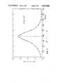
- FIG. 6is a graph illustrating the measured contrast ratio CR as a function of the polarizer orientation in an arrangement according to FIG. 4;
- FIG. 7is a graph illustrating the results corresponding to FIG. 6 for an arrangement according to FIG. 5;
- FIG. 8is a graph illustrating the computed curves of constant contrast ratio as a function of the polarizer orientation and the product ⁇ n ⁇ d for an arrangement with one polarizer and one reflector;
- FIG. 9is a graph illustrating the curves corresponding to FIG. 8 for an arrangement according to FIG. 5;
- FIG. 10is a graph illustrating the curves corresponding to FIG. 8 for an arrangement according to FIG. 4.
- the liquid crystal display shown in FIG. 1consists of two glass support plates 1 and 2 which form a cell with a border 3.
- the border 3as usual, consists of an epoxy cement which contains glass fiber spacers 4. Additional spacers 4 are randomly distributed between the support plates 1 and 2 over the entire viewing area of the display.
- a nematic liquid crystal 5 with positive dielectric anisotropy containing a chiral additiveis filled into the cell.
- the inner surfaces of each support plate 1 and 2have parallel strips of In 2 O 3 electrode layers 6 and 7, whereby the direction of the strips on the one support plate 1 is perpendicular to the direction of the strips on the other support plate 2.
- a dot matrix displayis formed.
- other electrode shapesare also possible, such as, e.g., the known seven-segment arrangement.
- Orientation layers 8 and 9are applied over the electrode layers 6 and 7 and over the the spaces between these electrode layers.
- a linear sheet-type linear polarizer 10is bonded to the outside of the front support plate 1.
- a linear polarizer 11is also bonded to the outside of the rear support plate 2.
- a diffusely scattering, metallic, external reflector 12is placed behind this polarizer 11 (indicated by the dashed line in FIG. 1).
- Such a reflectoris known, e.g. from CH-B-618018.
- the polarizer 11can also be left out. By this means the brightness is improved but the contrast ratio is lowered.
- FIG. 1athe situation is shown when, instead of an external reflector 12, an internal reflector 13 is used, as is known, e.g. from EP-B-060380. As the section shows, this reflector is placed between the electrode layer 7 and the orientation layer 9. Otherwise, except for the polarizer 11, the same elements are present as in FIG. 1.
- FIG. 2represents, for a typical liquid crystal, the theoretical relation between the tilt angle ⁇ of the local optical axis (i.e. the director) of the liquid crystal in the middle of the layer and the applied operating voltage U.
- the angle ⁇was measured in relation to the support plate.
- the tilt angle of the liquid crystal on the support plate in both casesamounts to 28°.
- the parameter ⁇the total twist angle of the liquid crystal within the display cell, runs through the values 210° (curve I), 240° (curve II), 270° (curve III), 300° (curve IV), 330° (curve V) and 360° (curve VI).
- the pitch pis so chosen that the d/p ratio is described by the following formula:
- the values of 210°, 240°, 270°, 300°, 330° and 360°therefore correspond to a d/p ration of 0.58, 0.67, 0.75, 0.83, 0.91 and 1.0.
- the pitch pis defined in accordance with common usage as the characteristic amount of natural twist produced in the undisturbed nematic liquid crystal by the addition of a chiral additive. The pitch is counted as positive in a system with right-handed twist and negative in a system with left-handed twist.
- the magnitude of the ratio of layer thickness d to pitch p of the liquid crystalbe in the range of 0.50 to 0.95, preferably between 0.65 and 0.85.
- the pitch pis adjusted by adding a specific weight percent of a chiral additive to the nematic liquid crystal. The weight percent depends on the type of liquid crystal and chiral additive and on the layer thickness d.
- the layer thickness dshould be less than 10 ⁇ m and the total twist angle ⁇ within the display cell should be between 180° and 360°, preferably between 240° and 300°.
- the transfer characteristic of the displayi.e. the transmission curve as a function of applied operating voltage
- the range of the bistable behavioris so narrowed that addressing can take place according to the usual multiplexing technique (cf., e.g., IEEE Trans. E1. Dev., Vol. ED-21, No. 2, February 1974, pages 146 to 155) with operating voltages outside this range. It was found that within this range the switching times are at least 100 times longer as outside this range.
- the transfer characteristic of the displayhas a similar shape to the curves in FIG. 2, except that the negative slope of the curves (here curves III to VI) should be replaced by a bistable region (hysteresis loop).
- the product of birefringence ⁇ n and layer thickness d of the liquid crystallies within the range 0.6 ⁇ m to 1.4 ⁇ m, preferably between 0.8 ⁇ m and 1.2 ⁇ m.
- the operation of the liquid crystal display of this invention in transmissioncan now be explained as follows: the light linearly polarized by the linear polarizer 10 penetrates the support plate 1 and strikes the liquid crystal aligned on the orientation layer 8 at an angle. Because of the total twist ⁇ and the double refracting properties of the liquid crystal, the originally linearly polarized light is elliptically but variably polarized, depending upon the applied operating voltage.
- the orientation direction of the orientation layer 9 and the direction of vibration of the rear linear polarizer 11also form a certain angle.
- orientation direction used hereis understood to be the projection of the direction of the local optical axis of the liquid crystal immediately adjacent to the orientation layer onto the plane of the orientation layer.
- the direction of vibration of the polarizeris understood to refer to the vibration direction of the electric field vector of the polarized light.
- the elliptically polarized light leaving the liquid crystalis absorbed in the rear polarizer 11, either almost completely or hardly at all, depending upon whether the principal axis of the elliptically polarized light is perpendicular or parallel to the direction of vibration of the polarizer 11.
- An optimum contrastis achieved by suitable choice of the above-mentioned angle between the orientation layers 8 and 9 and of the polarizers 10 and 11. This angle has a magnitude lying between 20° and 70°, preferably between 30° and 60°, with the sense being either clockwise or counter-clockwise.
- the clockwise senseis defined with respect to the incident direction of the light and the angle is taken in reference to the orientation direction of the orientation layer.
- the operating principleis essentially the same as in the transmissive mode.
- the optimum contrast in a system with only one polarizer 10is determined by appropriate choice of the angle between the direction of vibration of the front linear polarizer 10 and the orientation direction of the first orientation layer 8.
- FIGS. 4 and 5show exploded, perspective representations of the arrangement of the polarizers 10 and 11, the orientation layers 8 and 9 as well as the liquid crystal layer 5 located between these layers.
- the total twist ⁇ of the liquid crystal in the layeris made clear by a chain of liquid crystal molecules which are schematically represented by small rectangular platelets. Support plates, border and possible reflectors have been left out for sake of clarity.
- the elements of the cellare arranged along an axis pointing along the propagation direction of the incident light.
- the direction of vibration of the polarizers 10 and 11 as well as the orientation direction of the orientation layers 8 and 9are also indicated by arrows which lie in the corresponding planes perpendicular to the above-mentioned axis of the cell.
- This axis(incident direction of the light) defines a right-handed coordinate system in which angles are counted as positive in the clockwise sense and negative in the counter-clockwise sense.
- the examples of the liquid crystal molecules in the cases of FIGS. 4 and 5therefore form a left-handed screw which has a twist angle ⁇ of -270° in going out from the front orientation layer 8.
- the vibration directions of the polarizers 10 and 11are rotated from the orientation directions of the orientation layers 8 and 9, represented by the dashed lines in the polarizer planes, by the angles ⁇ and ⁇ .
- both angles ⁇ and ⁇are positive.
- only ⁇is positive, whereas ⁇ is negative.
- the angle specificationsalways refer to the rules laid down in FIGS. 4 and 5.
- the inventionhas especially proven to be useful in a reflective display cell with a layer thickness d of 7.6 ⁇ m and a total twist angle ⁇ of the liquid crystal of -270°.
- the d/p ratio in this caseis -0.75.
- the first orientation layer 8is produced by oblique vacuum deposition of SiO at an angle of 5° to the plate plane and aligns and adjoining liquid crystal molecules in such a way that the tilt angle between the local optical axis of the liquid crystal at the orientation layer and the projection of this optical axis on the plane plate, i.e. the orientation direction, amounts to 28°.
- the direction of vibration of the front polarizer 10 and the orientation direction of the orientation layer 8form an angle of about 30°.
- the second orientation layer 9is a rubbed polymer layer which gives a tilt angle of 1°.
- the liquid crystal 5consists of the nematic mixture ZLI-1840 from the firm of Merck, FRG, with 2.05 percent by weight of the chiral additive cholesteryl nonanoate. This liquid crystal has a positive dielectic anisotropy of +12.2 and a birefringence of 0.15.
- the temperature rangeextends from 258 K. to 363 K., and the viscosity is 1.18 ⁇ 10 -4 m 2 /s at 273 K. and 3.1 ⁇ 10 -3 m 2 /s at 293 K.
- the operating voltagesare 1.90 V for the non-selected state (dark) and 2.10 V for the selected state (bright).
- the displayIn the bright state, the display is completely achromatic, in the dark condition it is deep blue.
- an optical retardation platesuch as, e.g., a ⁇ /4 plate, is used between the front linear polarizer 10 and the front support plate 1, the color of the display can be correspondingly changed. It has an excellent range of viewing angles independent of the direction of the illumination.
- the on and off switching times of the displayare 0.4 s at 296 K.
- Another especially preferred embodiment of the inventionconsists of a reflective display cell with a 0.7 mm thick support plate 1 and a 0.5 mm thick support plate 2.
- the layer thicknessis 6.5 ⁇ m.
- This display cellis provided with a front polarizer 10, a rear polarizer 11 and an external reflector 12.
- Both orientation layers 8 and 9are prepared by oblique vacuum deposition of SiO at an angle of 50° to the plate plane. These layers orient the neighboring liquid crystal molecules in such a way that the optical axis of the liquid crystal forms a tilt angle of 28° with respect to the plate plane.
- the orientation layer 8 and 9are arranged so that the total twist ⁇ makes a left-handed spiral of -250°.
- the nematic mixture ZLI-1840 with a chiral additive of 2.56 weight percent of cholesteryl nonanoateis filled into the cell.
- the angle ⁇ between the vibration direction of the front linear polarizer 10 and the orientation direction of its associated orientation layer 8 and the angle ⁇ between the vibration direction of the rear linear polarizer 11 and the orientation direction of its associated orientation layer 9are ⁇ 45°. Contrast curves are given in FIG.
- V s and V nsare the usual select and non-select addressing voltages as given in the article appearing in IEEE Trans. El. Dev. that was already mentioned.
- the ratio V s /V nsis then 1.106 for a multiplex rate of 100:1.
- a liquid crystal mixtureconsisting of 95.6 wt. % ZLI-2392 (Merck), 2.5 wt. % S 811 (Merck) and 1.9 wt. % CB 15 (BDH) was used for these measurements.
- the total layer twist anglewas -270°, the surface tilt angle 24°, the layer thickness 6.3 ⁇ m and the birefringence 0.15.
- FIG. 8makes it clear that in the case of a cell operating in the reflective mode with one polarizer a maximal contrast ratio CR of about 3.6:1 is only then achieved if the angle ⁇ is about 20° and ⁇ n ⁇ d is approximately 1.13 ⁇ m. For this case a surface tilt angle of 28° was assumed.
- this inventionmakes possible a highly multiplexable, high contrast and fast liquid crystal display having a wide range of viewing angles, which in addition can be manufactured using the proven technology of the conventional TN (Twisted Nematic) display cells.
- FIG. 3is a diagrammatic representation of FIG. 3
Landscapes
- Physics & Mathematics (AREA)
- Nonlinear Science (AREA)
- General Physics & Mathematics (AREA)
- Optics & Photonics (AREA)
- Chemical & Material Sciences (AREA)
- Crystallography & Structural Chemistry (AREA)
- Liquid Crystal (AREA)
- Liquid Crystal Substances (AREA)
Abstract
Description
d/p=φ/360° (1)
______________________________________ curve A V.sub.s = 1.580 V contrast ratio = 19.8 V.sub.ns = 1.429 V curve B V.sub.s = 1.609 V contrast ratio = 11.8 V.sub.ns = 1.456 V ______________________________________
β+γ≅±90° (FIG. 4) (2)
β+γ≅0° (FIG. 5) (3)
Claims (15)
Applications Claiming Priority (4)
| Application Number | Priority Date | Filing Date | Title |
|---|---|---|---|
| CH381983ACH664027A5 (en) | 1983-07-12 | 1983-07-12 | LCD with twisted nematic crystal between support plates |
| CH3819/83 | 1983-07-12 | ||
| CH583583ACH665491A5 (en) | 1983-10-28 | 1983-10-28 | LCD with twisted nematic crystal between support plates |
| CH5835/83 | 1983-10-28 |
Related Parent Applications (1)
| Application Number | Title | Priority Date | Filing Date |
|---|---|---|---|
| US06/626,380ContinuationUS4634229A (en) | 1983-07-12 | 1984-06-29 | Liquid crystal display |
Publications (2)
| Publication Number | Publication Date |
|---|---|
| US4697884Atrue US4697884A (en) | 1987-10-06 |
| US4697884B1 US4697884B1 (en) | 1990-08-28 |
Family
ID=25693920
Family Applications (2)
| Application Number | Title | Priority Date | Filing Date |
|---|---|---|---|
| US06/626,380Expired - LifetimeUS4634229A (en) | 1983-07-12 | 1984-06-29 | Liquid crystal display |
| US06/908,667Expired - LifetimeUS4697884A (en) | 1983-07-12 | 1986-09-17 | Liquid crystal display having degree of twist and thickness for improved multiplexing |
Family Applications Before (1)
| Application Number | Title | Priority Date | Filing Date |
|---|---|---|---|
| US06/626,380Expired - LifetimeUS4634229A (en) | 1983-07-12 | 1984-06-29 | Liquid crystal display |
Country Status (14)
| Country | Link |
|---|---|
| US (2) | US4634229A (en) |
| EP (1) | EP0131216B1 (en) |
| KR (1) | KR900008064B1 (en) |
| CA (1) | CA1242784A (en) |
| DD (1) | DD222433A5 (en) |
| DE (2) | DE3467044D1 (en) |
| FR (1) | FR2549268B1 (en) |
| GB (1) | GB2143336B (en) |
| HK (1) | HK54890A (en) |
| IN (1) | IN161652B (en) |
| NL (1) | NL8402189A (en) |
| NO (1) | NO167241C (en) |
| PH (1) | PH24617A (en) |
| SG (1) | SG20690G (en) |
Cited By (39)
| Publication number | Priority date | Publication date | Assignee | Title |
|---|---|---|---|---|
| US4904060A (en)* | 1987-11-23 | 1990-02-27 | Asulab, S.A. | Liquid crystal display cell having a diffusely-reflective counter electrode |
| US4906073A (en)* | 1987-07-29 | 1990-03-06 | Hitachi, Ltd. | Liquid crystal display device using nematic liquid crystal having twisted helical structure and a phase correction plate |
| US4917465A (en)* | 1989-03-28 | 1990-04-17 | In Focus Systems, Inc. | Color display system |
| US4923286A (en)* | 1986-02-27 | 1990-05-08 | Asulab S.A. | Display cell |
| US4936654A (en)* | 1988-01-28 | 1990-06-26 | Sanyo Electric Co., Ltd. | Liquid crystal display device |
| US4941737A (en)* | 1987-10-07 | 1990-07-17 | Sharp Kabushiki Kaisha | Liquid-crystal display device using twisted nematic liquid crystal molecules |
| US4957349A (en)* | 1987-04-06 | 1990-09-18 | Commissariat A L'energie Atomique | Active matrix screen for the color display of television pictures, control system and process for producing said screen |
| US4973137A (en)* | 1987-11-04 | 1990-11-27 | Sharp Kabushiki Kaisha | Liquid crystal display device with compensation layers |
| US4991924A (en)* | 1989-05-19 | 1991-02-12 | Cornell Research Foundation, Inc. | Optical switches using cholesteric or chiral nematic liquid crystals and method of using same |
| US4999619A (en)* | 1987-06-10 | 1991-03-12 | U.S. Philips Corporation | Electro-optic display device for use in the reflection mode |
| US5044735A (en)* | 1985-11-29 | 1991-09-03 | Konishiroku Photo Industry Co., Ltd. | Liquid crystal display device for providing sufficiently high contrast ratio and excellent response time |
| US5050965A (en)* | 1989-09-01 | 1991-09-24 | In Focus Systems, Inc. | Color display using supertwisted nematic liquid crystal material |
| US5054910A (en)* | 1988-10-04 | 1991-10-08 | Sharp Kabushiki Kaisha | Projection apparatus |
| US5058998A (en)* | 1988-09-16 | 1991-10-22 | Casio Computer Co., Ltd. | Liquid crystal display devide with a twisted alignment state |
| US5071228A (en)* | 1988-12-24 | 1991-12-10 | Nokia Unterhaltungselektronik | Black-white liquid crystal display having an insulation layer for blocking the diffusion of sodium ions from the glass of the cell plate to the polyphenylene of the orientation layer |
| US5089810A (en)* | 1990-04-09 | 1992-02-18 | Computer Accessories Corporation | Stacked display panel construction and method of making same |
| US5093741A (en)* | 1989-10-06 | 1992-03-03 | Kabushiki Kaisha Toshiba | Liquid crystal display device |
| US5099345A (en)* | 1987-03-10 | 1992-03-24 | Sharp Kabushiki Kaisha | Colored liquid-crystal display device having supertwisted nematic liquid crystal and color filters |
| US5105289A (en)* | 1988-07-14 | 1992-04-14 | Seiko Epson Corporation | Reflection type electrooptical device and a projection type display apparatus using the same |
| US5119220A (en)* | 1988-01-28 | 1992-06-02 | Sanyo Electric Co., Ltd. | Liquid crystal display device with a phase plate for shadow compensation |
| US5153568A (en)* | 1988-07-21 | 1992-10-06 | Proxima Corporation | Liquid crystal display panel system and method of using same |
| US5184156A (en)* | 1991-11-12 | 1993-02-02 | Reliant Laser Corporation | Glasses with color-switchable, multi-layered lenses |
| US5302946A (en)* | 1988-07-21 | 1994-04-12 | Leonid Shapiro | Stacked display panel construction and method of making same |
| US5327269A (en)* | 1992-05-13 | 1994-07-05 | Standish Industries, Inc. | Fast switching 270° twisted nematic liquid crystal device and eyewear incorporating the device |
| US5432624A (en)* | 1993-12-03 | 1995-07-11 | Reliant Technologies, Inc. | Optical display unit in which light passes a first cell, reflects, then passes a second cell |
| US5550664A (en)* | 1993-12-24 | 1996-08-27 | Sharp Kabushiki Kaisha | Liquid crystal display device |
| US5579142A (en)* | 1994-10-14 | 1996-11-26 | Sharp Kabushiki Kaisha | Liquid crystal display device having pleochroic dye and particular relationship of ratio d/po and twist angle |
| US5619356A (en)* | 1993-09-16 | 1997-04-08 | Sharp Kabushiki Kaisha | Reflective liquid crystal display device having a compensator with a retardation value between 0.15 μm and 0.38 μm and a single polarizer |
| US5696570A (en)* | 1992-04-16 | 1997-12-09 | Merck Patent Gesellschaft Mit Beschrankter Haftung | TN cell having improved display of grey shades |
| US5876626A (en)* | 1988-10-20 | 1999-03-02 | Merck Patent Gesellschaft Mit Beschrankter Haftung | Supertwist liquid crystal display |
| US5986732A (en)* | 1995-01-23 | 1999-11-16 | Asahi Glass Company Ltd. | Color liquid crystal display apparatus |
| USRE36654E (en)* | 1989-03-28 | 2000-04-11 | In Focus Systems, Inc. | Stacked LCD color display |
| US6094252A (en)* | 1995-09-05 | 2000-07-25 | Sharp Kabushiki Kaisha | GH LCD having particular parameters and characteristics |
| US6258443B1 (en) | 1994-09-28 | 2001-07-10 | Reflexite Corporation | Textured retroreflective prism structures and molds for forming same |
| US20040021818A1 (en)* | 1966-05-09 | 2004-02-05 | Yuka Utsumi | Active matrix type liquid crystal display apparatus |
| US6714276B2 (en)* | 2000-02-08 | 2004-03-30 | Sharp Kabushiki Kaisha | Liquid crystal display device |
| US6727968B1 (en)* | 1997-10-08 | 2004-04-27 | Hewlett-Packard Development Company, L.P. | Liquid crystal device alignment |
| US20040080694A1 (en)* | 1992-06-30 | 2004-04-29 | Semiconductor Energy Laboratory Co., Ltd. | Electro-optical device |
| US20110019112A1 (en)* | 1991-02-21 | 2011-01-27 | Gene Dolgoff | Projection System with Enhanced Brightness |
Families Citing this family (57)
| Publication number | Priority date | Publication date | Assignee | Title |
|---|---|---|---|---|
| US4596446B2 (en)* | 1982-06-29 | 1997-03-18 | Secr Defence Brit | Liquid crystal devices with particular cholestric pitch-cell thickness ratio |
| JPS6050511A (en)* | 1983-08-31 | 1985-03-20 | Hitachi Ltd | Liquid crystal display element |
| JPS61193125A (en)* | 1985-02-22 | 1986-08-27 | Hitachi Ltd | Liquid crystal display element |
| JPS61210324A (en)* | 1985-03-15 | 1986-09-18 | Hitachi Ltd | Liquid crystal display element |
| JPH0656459B2 (en)* | 1985-04-05 | 1994-07-27 | 株式会社日立製作所 | Liquid crystal display element |
| CA1281114C (en)* | 1985-09-25 | 1991-03-05 | Kokichi Ito | Liquid crystal electro-optical element with adhesive particles |
| US5215677A (en)* | 1985-09-27 | 1993-06-01 | Sanyo Electric Co., Ltd. | Liquid crystal display device |
| DE3684977D1 (en)* | 1985-09-27 | 1992-05-27 | Sanyo Electric Co | LIQUID CRYSTAL DISPLAY DEVICE. |
| JPS62194224A (en)* | 1986-02-20 | 1987-08-26 | Sharp Corp | Twisted nematic type liquid crystal display element |
| US4726659A (en)* | 1986-02-24 | 1988-02-23 | Rca Corporation | Display device having different alignment layers |
| DE3609141A1 (en)* | 1986-03-19 | 1987-09-24 | Merck Patent Gmbh | ELECTROOPTICAL DISPLAY ELEMENT |
| US5188758A (en)* | 1986-03-19 | 1993-02-23 | Merck Patent Gesellschaft Mit Beschraenkter Haftung | Electrooptical display element using a supertwist liquid crystal having specified elastic constants |
| EP1156362A1 (en)* | 1986-05-19 | 2001-11-21 | Seiko Epson Corporation | A liquid crystal display device |
| US4776674A (en)* | 1986-06-25 | 1988-10-11 | American Telephone And Telegraph Company, At&T Bell Laboratories | Liquid crystal device with chemically-induced high-tilt alignment coating |
| US4779958A (en)* | 1986-06-28 | 1988-10-25 | Kabushiki Kaisha Toshiba | Liquid crystal device having different natural and induced twists |
| US4818074A (en)* | 1986-09-03 | 1989-04-04 | Ricoh Company, Ltd. | Projection device for irradiating a light to a display device and optically magnifying and projecting a reflection light therefrom |
| DE3774977D1 (en)* | 1986-09-12 | 1992-01-16 | Hoffmann La Roche | LIQUID CRYSTAL DISPLAY. |
| JP2676508B2 (en)* | 1986-09-12 | 1997-11-17 | コニカ株式会社 | Liquid crystal display |
| JPS63167331A (en)* | 1986-12-29 | 1988-07-11 | Sharp Corp | Twisted nematic liquid crystal display element |
| JPS63234225A (en)* | 1987-03-23 | 1988-09-29 | Sharp Corp | liquid crystal display device |
| GB2204174B (en)* | 1987-04-23 | 1991-03-13 | Seiko Instr Inc | Electro-optical modulator |
| JPS6421416A (en)* | 1987-07-17 | 1989-01-24 | Hitachi Ltd | Liquid crystal display element |
| US5044733A (en)* | 1987-08-19 | 1991-09-03 | Ricoh Company, Ltd. | Super twisted nematic liquid crystal display device having the standard deviation of the spherical grains being not more than 3% and the dispersion quantity of the spherical grains being 100-200 grains/mm2 |
| DE3887436T2 (en)* | 1987-10-13 | 1994-05-11 | Fujitsu Ltd | Liquid crystal display panel. |
| JPH07117664B2 (en)* | 1987-12-03 | 1995-12-18 | シャープ株式会社 | Liquid crystal display |
| DE3741997C2 (en)* | 1987-12-11 | 1997-07-17 | Vdo Schindling | Method for driving an STN liquid crystal cell |
| DE3807958B4 (en)* | 1988-03-10 | 2004-03-18 | Merck Patent Gmbh | Super twisted liquid crystal display element |
| DE3835803A1 (en)* | 1988-03-10 | 1990-04-26 | Merck Patent Gmbh | SUPERTWIST-LIQUID CRYSTAL DISPLAY ELEMENT AND LIQUID MIXTURE |
| US5082353A (en)* | 1988-05-11 | 1992-01-21 | Kabushiki Kaisha Toshiba | Liquid-crystal display apparatus |
| JP2621385B2 (en)* | 1988-07-06 | 1997-06-18 | セイコーエプソン株式会社 | Electro-optical device |
| EP0352101B1 (en)* | 1988-07-19 | 1994-09-14 | Sharp Kabushiki Kaisha | A double-layered type liquid-crystal display device |
| US4944578A (en)* | 1988-07-21 | 1990-07-31 | Telex Communications | Color graphic imager utilizing a liquid crystal display |
| DE3835804B4 (en)* | 1988-10-20 | 2006-12-28 | Merck Patent Gmbh | Nematic liquid-crystal mixture |
| JP2784205B2 (en)* | 1989-04-14 | 1998-08-06 | コニカ株式会社 | Transmissive liquid crystal display |
| US5229031A (en)* | 1989-05-17 | 1993-07-20 | Seiko Epson Corporation | Liquid crystal display device |
| DE3923064B4 (en)* | 1989-07-13 | 2004-08-05 | Merck Patent Gmbh | Liquid crystal mixture and Supertwist liquid crystal display containing it |
| JP2924055B2 (en)* | 1989-12-08 | 1999-07-26 | セイコーエプソン株式会社 | Reflective liquid crystal display |
| JP2717731B2 (en)* | 1991-02-08 | 1998-02-25 | 株式会社日立製作所 | Liquid crystal display device |
| JPH03248121A (en)* | 1991-02-08 | 1991-11-06 | Hitachi Ltd | liquid crystal display element |
| EP0559137B1 (en)* | 1992-03-03 | 1998-06-03 | Matsushita Electric Industrial Co., Ltd. | Active matrix type twisted nematic liquid crystal display |
| JP3634390B2 (en)* | 1992-07-16 | 2005-03-30 | セイコーエプソン株式会社 | Liquid crystal electro-optic element |
| US5574583A (en)* | 1994-08-02 | 1996-11-12 | Hyundai Electronics Industries Co. Ltd. | Liquid crystal display device having a compensation layer and method for fabricating the same |
| KR100254647B1 (en) | 1995-05-17 | 2000-05-01 | 야스카와 히데아키 | Liquid crystal display, its driving method, driving circuit and power circuit device used therein |
| JPH0850271A (en)* | 1995-07-10 | 1996-02-20 | Hitachi Ltd | Liquid crystal display element |
| US5731404A (en) | 1995-11-01 | 1998-03-24 | E. I. Du Pont De Nemours And Company | Polyimide film from pyromellitic dianhydride and a bis(4-aminophenoxy) aromatic compound as an alignment layer for liquid crystal displays |
| GB9608175D0 (en)* | 1996-04-19 | 1996-06-26 | Ncr Int Inc | Method of controlling veiwability of a display screen and a device therefor |
| TW510504U (en) | 1996-05-10 | 2002-11-11 | Citizen Watch Co Ltd | Liquid crystal optical valve |
| JP3722920B2 (en)* | 1996-08-27 | 2005-11-30 | 株式会社リコー | Plastic film liquid crystal display element |
| DE10047091A1 (en)* | 2000-09-21 | 2002-04-11 | Merck Patent Gmbh | Liquid crystalline mixtures |
| DE10253874A1 (en)* | 2002-11-12 | 2004-05-27 | Carl Zeiss Smt Ag | Method for forming optical functional component for adjusting micro lithographic projection illumination installations, using charge coupled device (CCD) camera |
| SI21526A (en)* | 2003-05-16 | 2004-12-31 | Institut "Jožef Stefan" | High contrast, wide viewing angle lcd light-switching element |
| CN101441365B (en)* | 2005-04-18 | 2010-11-03 | 胜华科技股份有限公司 | Bistable liquid crystal display device |
| DE102009017301A1 (en) | 2009-02-21 | 2010-08-26 | Robert Bosch Gmbh | Gear transmission with a arranged on a hollow shaft gear |
| FR2988223B1 (en) | 2012-03-19 | 2016-09-02 | Solarwell | LIGHT EMITTING DEVICE CONTAINING APLATISED ANISOTROPIC SEMICONDUCTOR COLLOIDAL NANOCRISTALS AND PROCESS FOR PRODUCING SUCH DEVICES |
| WO2013140083A1 (en) | 2012-03-19 | 2013-09-26 | Solarwell | Light-emitting device containing flattened anisotropic colloidal semiconductor nanocrystals and processes for manufacturing such devices |
| JP2017526865A (en)† | 2014-05-20 | 2017-09-14 | ノラ,パウロ デ | Extendable hose and hose assembly |
| US11086162B1 (en)* | 2020-04-26 | 2021-08-10 | Tcl China Star Optoelectronics Technology Co., Ltd. | Display panel and display device |
Citations (12)
| Publication number | Priority date | Publication date | Assignee | Title |
|---|---|---|---|---|
| US3656834A (en)* | 1970-12-09 | 1972-04-18 | Ibm | Additive for liquid crystal material |
| US4143947A (en)* | 1976-06-21 | 1979-03-13 | General Electric Company | Method for improving the response time of a display device utilizing a twisted nematic liquid crystal composition |
| FR2416519A1 (en)* | 1978-02-06 | 1979-08-31 | Ebauches Sa | PASSIVE ELECTRO-OPTICAL DISPLAY CELL |
| GB2076554A (en)* | 1980-05-09 | 1981-12-02 | Hitachi Ltd | Liquid crystal display device |
| GB2087583A (en)* | 1980-10-20 | 1982-05-26 | Western Electric Co | Bistable liquid crystal twist cell |
| JPS57133438A (en)* | 1981-02-13 | 1982-08-18 | Hitachi Ltd | Liquid crystal display device |
| US4362771A (en)* | 1980-10-20 | 1982-12-07 | Hitachi, Ltd. | Liquid crystal display element with gap controlling material and process for production thereof |
| US4496220A (en)* | 1977-03-21 | 1985-01-29 | U.S. Philips Corporation | Information display device comprising a liquid crystal cell |
| US4505548A (en)* | 1980-10-20 | 1985-03-19 | At&T Bell Laboratories | Bistable liquid crystal twist cell |
| US4521080A (en)* | 1974-07-01 | 1985-06-04 | Sharp Kabushiki Kaisha | Field effect mode liquid crystal display |
| US4564266A (en)* | 1982-04-28 | 1986-01-14 | Centre National De La Recherche Scientifique (Cnrs) | Electro-optical devices using liquid crystals having a twist in a plane perpendicular to substrates |
| US4579425A (en)* | 1982-07-29 | 1986-04-01 | Sharp Kabushiki Kaisha | Multiplexable liquid crystal display with reduced hysteresis |
Family Cites Families (2)
| Publication number | Priority date | Publication date | Assignee | Title |
|---|---|---|---|---|
| JPS5352140A (en)* | 1976-10-22 | 1978-05-12 | Hitachi Ltd | Liquid crystal display device |
| ATE34468T1 (en)* | 1982-06-29 | 1988-06-15 | Secr Defence Brit | LIQUID CRYSTAL DEVICES. |
- 1984
- 1984-06-19ININ448/MAS/84Apatent/IN161652B/enunknown
- 1984-06-28EPEP84107507Apatent/EP0131216B1/ennot_activeExpired
- 1984-06-28DEDE8484107507Tpatent/DE3467044D1/ennot_activeExpired
- 1984-06-29DEDE19843423993patent/DE3423993A1/enactiveGranted
- 1984-06-29USUS06/626,380patent/US4634229A/ennot_activeExpired - Lifetime
- 1984-07-09NONO842799Apatent/NO167241C/ennot_activeIP Right Cessation
- 1984-07-09KRKR1019840003975Apatent/KR900008064B1/ennot_activeExpired
- 1984-07-10FRFR8410952Apatent/FR2549268B1/ennot_activeExpired
- 1984-07-10PHPH30959Apatent/PH24617A/enunknown
- 1984-07-10DDDD84265107Apatent/DD222433A5/enunknown
- 1984-07-10NLNL8402189Apatent/NL8402189A/ennot_activeApplication Discontinuation
- 1984-07-12GBGB08417776Apatent/GB2143336B/ennot_activeExpired
- 1984-07-12CACA000458749Apatent/CA1242784A/ennot_activeExpired
- 1986
- 1986-09-17USUS06/908,667patent/US4697884A/ennot_activeExpired - Lifetime
- 1990
- 1990-03-14SGSG206/90Apatent/SG20690G/enunknown
- 1990-07-19HKHK548/90Apatent/HK54890A/ennot_activeIP Right Cessation
Patent Citations (13)
| Publication number | Priority date | Publication date | Assignee | Title |
|---|---|---|---|---|
| US3656834A (en)* | 1970-12-09 | 1972-04-18 | Ibm | Additive for liquid crystal material |
| US4521080A (en)* | 1974-07-01 | 1985-06-04 | Sharp Kabushiki Kaisha | Field effect mode liquid crystal display |
| US4143947A (en)* | 1976-06-21 | 1979-03-13 | General Electric Company | Method for improving the response time of a display device utilizing a twisted nematic liquid crystal composition |
| US4496220A (en)* | 1977-03-21 | 1985-01-29 | U.S. Philips Corporation | Information display device comprising a liquid crystal cell |
| FR2416519A1 (en)* | 1978-02-06 | 1979-08-31 | Ebauches Sa | PASSIVE ELECTRO-OPTICAL DISPLAY CELL |
| GB2017327A (en)* | 1978-02-06 | 1979-10-03 | Ebauches Sa | Electro-optic passive display cell |
| GB2076554A (en)* | 1980-05-09 | 1981-12-02 | Hitachi Ltd | Liquid crystal display device |
| US4505548A (en)* | 1980-10-20 | 1985-03-19 | At&T Bell Laboratories | Bistable liquid crystal twist cell |
| US4362771A (en)* | 1980-10-20 | 1982-12-07 | Hitachi, Ltd. | Liquid crystal display element with gap controlling material and process for production thereof |
| GB2087583A (en)* | 1980-10-20 | 1982-05-26 | Western Electric Co | Bistable liquid crystal twist cell |
| JPS57133438A (en)* | 1981-02-13 | 1982-08-18 | Hitachi Ltd | Liquid crystal display device |
| US4564266A (en)* | 1982-04-28 | 1986-01-14 | Centre National De La Recherche Scientifique (Cnrs) | Electro-optical devices using liquid crystals having a twist in a plane perpendicular to substrates |
| US4579425A (en)* | 1982-07-29 | 1986-04-01 | Sharp Kabushiki Kaisha | Multiplexable liquid crystal display with reduced hysteresis |
Non-Patent Citations (12)
| Title |
|---|
| British Application 82 18821, filed Jun. 29, 1982; published Jan. 25, 1984 (Raynes).* |
| British Application 82-18821, filed Jun. 29, 1982; published Jan. 25, 1984 (Raynes). |
| Japanese Publ. 60 16225 and 60 162226, published Aug. 24, 1985 (Hitachi 4).* |
| Japanese Publ. 60 73525, published Apr. 25, 1985 (Hitachi 3).* |
| Japanese Publ. 60-16225 and 60-162226, published Aug. 24, 1985 (Hitachi 4). |
| Japanese Publ. 60-73525, published Apr. 25, 1985 (Hitachi 3). |
| Japanese Publication 57 133438, published Aug. 18, 1982 (Hitachi 1).* |
| Japanese Publication 57-133438, published Aug. 18, 1982 (Hitachi 1). |
| Japanese Publication 60 5011, published Mar. 20, 1985 (Hitachi 2).* |
| Japanese Publication 60-5011, published Mar. 20, 1985 (Hitachi 2). |
| Nara et al., "Multiplexing for the Guest--Host Mode Using a Nematic Cholestric Mixture With Long Pitch", J. Appl. Phys., 49(7), Jul. 1978, pp. 4277-4279. |
| Nara et al., Multiplexing for the Guest Host Mode Using a Nematic Cholestric Mixture With Long Pitch , J. Appl. Phys., 49(7), Jul. 1978, pp. 4277 4279.* |
Cited By (46)
| Publication number | Priority date | Publication date | Assignee | Title |
|---|---|---|---|---|
| US20040021818A1 (en)* | 1966-05-09 | 2004-02-05 | Yuka Utsumi | Active matrix type liquid crystal display apparatus |
| US5044735A (en)* | 1985-11-29 | 1991-09-03 | Konishiroku Photo Industry Co., Ltd. | Liquid crystal display device for providing sufficiently high contrast ratio and excellent response time |
| US4923286A (en)* | 1986-02-27 | 1990-05-08 | Asulab S.A. | Display cell |
| US5099345A (en)* | 1987-03-10 | 1992-03-24 | Sharp Kabushiki Kaisha | Colored liquid-crystal display device having supertwisted nematic liquid crystal and color filters |
| US4957349A (en)* | 1987-04-06 | 1990-09-18 | Commissariat A L'energie Atomique | Active matrix screen for the color display of television pictures, control system and process for producing said screen |
| US4999619A (en)* | 1987-06-10 | 1991-03-12 | U.S. Philips Corporation | Electro-optic display device for use in the reflection mode |
| US4906073A (en)* | 1987-07-29 | 1990-03-06 | Hitachi, Ltd. | Liquid crystal display device using nematic liquid crystal having twisted helical structure and a phase correction plate |
| US4941737A (en)* | 1987-10-07 | 1990-07-17 | Sharp Kabushiki Kaisha | Liquid-crystal display device using twisted nematic liquid crystal molecules |
| US4973137A (en)* | 1987-11-04 | 1990-11-27 | Sharp Kabushiki Kaisha | Liquid crystal display device with compensation layers |
| US4904060A (en)* | 1987-11-23 | 1990-02-27 | Asulab, S.A. | Liquid crystal display cell having a diffusely-reflective counter electrode |
| US4936654A (en)* | 1988-01-28 | 1990-06-26 | Sanyo Electric Co., Ltd. | Liquid crystal display device |
| US5119220A (en)* | 1988-01-28 | 1992-06-02 | Sanyo Electric Co., Ltd. | Liquid crystal display device with a phase plate for shadow compensation |
| US5105289A (en)* | 1988-07-14 | 1992-04-14 | Seiko Epson Corporation | Reflection type electrooptical device and a projection type display apparatus using the same |
| US5302946A (en)* | 1988-07-21 | 1994-04-12 | Leonid Shapiro | Stacked display panel construction and method of making same |
| US5153568A (en)* | 1988-07-21 | 1992-10-06 | Proxima Corporation | Liquid crystal display panel system and method of using same |
| US5058998A (en)* | 1988-09-16 | 1991-10-22 | Casio Computer Co., Ltd. | Liquid crystal display devide with a twisted alignment state |
| US5054910A (en)* | 1988-10-04 | 1991-10-08 | Sharp Kabushiki Kaisha | Projection apparatus |
| US5876626A (en)* | 1988-10-20 | 1999-03-02 | Merck Patent Gesellschaft Mit Beschrankter Haftung | Supertwist liquid crystal display |
| US5071228A (en)* | 1988-12-24 | 1991-12-10 | Nokia Unterhaltungselektronik | Black-white liquid crystal display having an insulation layer for blocking the diffusion of sodium ions from the glass of the cell plate to the polyphenylene of the orientation layer |
| USRE36654E (en)* | 1989-03-28 | 2000-04-11 | In Focus Systems, Inc. | Stacked LCD color display |
| US4917465A (en)* | 1989-03-28 | 1990-04-17 | In Focus Systems, Inc. | Color display system |
| US4991924A (en)* | 1989-05-19 | 1991-02-12 | Cornell Research Foundation, Inc. | Optical switches using cholesteric or chiral nematic liquid crystals and method of using same |
| US5050965A (en)* | 1989-09-01 | 1991-09-24 | In Focus Systems, Inc. | Color display using supertwisted nematic liquid crystal material |
| US5093741A (en)* | 1989-10-06 | 1992-03-03 | Kabushiki Kaisha Toshiba | Liquid crystal display device |
| US5089810A (en)* | 1990-04-09 | 1992-02-18 | Computer Accessories Corporation | Stacked display panel construction and method of making same |
| US20110019112A1 (en)* | 1991-02-21 | 2011-01-27 | Gene Dolgoff | Projection System with Enhanced Brightness |
| US5184156A (en)* | 1991-11-12 | 1993-02-02 | Reliant Laser Corporation | Glasses with color-switchable, multi-layered lenses |
| US5696570A (en)* | 1992-04-16 | 1997-12-09 | Merck Patent Gesellschaft Mit Beschrankter Haftung | TN cell having improved display of grey shades |
| US5327269A (en)* | 1992-05-13 | 1994-07-05 | Standish Industries, Inc. | Fast switching 270° twisted nematic liquid crystal device and eyewear incorporating the device |
| US20040080694A1 (en)* | 1992-06-30 | 2004-04-29 | Semiconductor Energy Laboratory Co., Ltd. | Electro-optical device |
| US7567320B2 (en)* | 1992-06-30 | 2009-07-28 | Semiconductor Energy Laboratory Co., Ltd. | Electro-optical device with liquid crystal |
| US5619356A (en)* | 1993-09-16 | 1997-04-08 | Sharp Kabushiki Kaisha | Reflective liquid crystal display device having a compensator with a retardation value between 0.15 μm and 0.38 μm and a single polarizer |
| US5432624A (en)* | 1993-12-03 | 1995-07-11 | Reliant Technologies, Inc. | Optical display unit in which light passes a first cell, reflects, then passes a second cell |
| US5550664A (en)* | 1993-12-24 | 1996-08-27 | Sharp Kabushiki Kaisha | Liquid crystal display device |
| US6258443B1 (en) | 1994-09-28 | 2001-07-10 | Reflexite Corporation | Textured retroreflective prism structures and molds for forming same |
| US5579142A (en)* | 1994-10-14 | 1996-11-26 | Sharp Kabushiki Kaisha | Liquid crystal display device having pleochroic dye and particular relationship of ratio d/po and twist angle |
| US5986732A (en)* | 1995-01-23 | 1999-11-16 | Asahi Glass Company Ltd. | Color liquid crystal display apparatus |
| US6229587B1 (en) | 1995-01-23 | 2001-05-08 | Asahi Glass Company Ltd. | Color liquid crystal display apparatus |
| US6094252A (en)* | 1995-09-05 | 2000-07-25 | Sharp Kabushiki Kaisha | GH LCD having particular parameters and characteristics |
| US20060087482A1 (en)* | 1995-10-23 | 2006-04-27 | Yuka Utsumi | Active matrix type liquid crystal display apparatus |
| US7209211B2 (en)* | 1995-10-23 | 2007-04-24 | Hitachi, Ltd. | Active matrix type liquid crystal display apparatus |
| US7433012B2 (en) | 1995-10-23 | 2008-10-07 | Hitachi, Ltd. | Active matrix type liquid crystal display apparatus |
| US20090040438A1 (en)* | 1995-10-23 | 2009-02-12 | Yuka Utsumi | Active Matrix Type Liquid Crystal Display Apparatus |
| US7684005B2 (en) | 1995-10-23 | 2010-03-23 | Hitachi, Ltd. | Active matrix type liquid crystal display apparatus |
| US6727968B1 (en)* | 1997-10-08 | 2004-04-27 | Hewlett-Packard Development Company, L.P. | Liquid crystal device alignment |
| US6714276B2 (en)* | 2000-02-08 | 2004-03-30 | Sharp Kabushiki Kaisha | Liquid crystal display device |
Also Published As
| Publication number | Publication date |
|---|---|
| SG20690G (en) | 1990-07-06 |
| FR2549268A1 (en) | 1985-01-18 |
| KR900008064B1 (en) | 1990-10-31 |
| IN161652B (en) | 1988-01-09 |
| DE3467044D1 (en) | 1987-12-03 |
| CA1242784A (en) | 1988-10-04 |
| GB2143336B (en) | 1987-04-01 |
| EP0131216A2 (en) | 1985-01-16 |
| EP0131216A3 (en) | 1985-03-13 |
| DE3423993C2 (en) | 1988-06-23 |
| NO167241C (en) | 1991-10-16 |
| GB2143336A (en) | 1985-02-06 |
| FR2549268B1 (en) | 1985-12-13 |
| NL8402189A (en) | 1985-02-01 |
| KR850001438A (en) | 1985-03-18 |
| US4697884B1 (en) | 1990-08-28 |
| US4634229A (en) | 1987-01-06 |
| GB8417776D0 (en) | 1984-08-15 |
| EP0131216B1 (en) | 1987-10-28 |
| NO167241B (en) | 1991-07-08 |
| PH24617A (en) | 1990-08-17 |
| HK54890A (en) | 1990-07-27 |
| NO842799L (en) | 1985-01-14 |
| DD222433A5 (en) | 1985-05-15 |
| DE3423993A1 (en) | 1985-01-24 |
Similar Documents
| Publication | Publication Date | Title |
|---|---|---|
| US4697884A (en) | Liquid crystal display having degree of twist and thickness for improved multiplexing | |
| US5684551A (en) | Reflective type liquid crystal display device with phase compensator and reflector with undulating surface | |
| US5576867A (en) | Liquid crystal switching elements having a parallel electric field and βo which is not 0° or 90° | |
| JPH041330B2 (en) | ||
| US5119216A (en) | Electro-optical device | |
| US5126868A (en) | Color compensated double layered liquid crystal display device | |
| KR920004895B1 (en) | Liquid crystal display | |
| US5568287A (en) | Liquid crystal device with optical means of high refractive index at pixels and low refractive index between pixels | |
| US5048933A (en) | Transmission type liquid crystal display device | |
| US4904058A (en) | Liquid crystal display panel | |
| JPS61231523A (en) | Liquid crystal display element | |
| US4579425A (en) | Multiplexable liquid crystal display with reduced hysteresis | |
| EP0259822A1 (en) | Liquid crystal display device | |
| JPH0196625A (en) | liquid crystal display device | |
| US20020180913A1 (en) | Reverse reflectance mode direct-view liquid crystal display employing a liquid crystal having a characteristic wavelength in the non-visible spectrum | |
| JPH01147432A (en) | liquid crystal display device | |
| US4974940A (en) | Liquid crystal display device | |
| US6181400B1 (en) | Discotic-type twist-film compensated single-domain or two-domain twisted nematic liquid crystal displays | |
| JPH04140722A (en) | Liquid crystal display device | |
| US7042536B2 (en) | Liquid crystal display element | |
| US20010005246A1 (en) | Liquid crystal display device | |
| KR19980033500A (en) | Reflective bistable nematic liquid crystal display | |
| US5682217A (en) | Liquid crystal display device in which no sticking phenomenon occurs with high contrast | |
| JP2615715B2 (en) | Manufacturing method of electro-optical element | |
| JP3007555B2 (en) | Liquid crystal display device |
Legal Events
| Date | Code | Title | Description |
|---|---|---|---|
| STCF | Information on status: patent grant | Free format text:PATENTED CASE | |
| FEPP | Fee payment procedure | Free format text:PAYOR NUMBER ASSIGNED (ORIGINAL EVENT CODE: ASPN); ENTITY STATUS OF PATENT OWNER: LARGE ENTITY | |
| RR | Request for reexamination filed | Effective date:19900117 | |
| B1 | Reexamination certificate first reexamination | ||
| FPAY | Fee payment | Year of fee payment:4 | |
| AS | Assignment | Owner name:BBC BROWN BOVERI AG, SWITZERLAND Free format text:CHANGE OF NAME;ASSIGNOR:BBC BROWN BOVERI & COMPANY LTD.;REEL/FRAME:007232/0062 Effective date:19870602 | |
| AS | Assignment | Owner name:ASEA BROWN BOVER LTD., SWITZERLAND Free format text:ASSIGNMENT OF ASSIGNORS INTEREST;ASSIGNOR:BBC BROWN BOVERI AG;REEL/FRAME:007247/0454 Effective date:19941208 | |
| FPAY | Fee payment | Year of fee payment:8 | |
| FPAY | Fee payment | Year of fee payment:12 | |
| AS | Assignment | Owner name:ABB (SWITZERLAND) LTD., SWITZERLAND Free format text:CHANGE OF NAME;ASSIGNOR:ASEA BROWN BOVERI LTD.;REEL/FRAME:012295/0011 Effective date:19990910 | |
| AS | Assignment | Owner name:ABB SWITZERLAND HOLDING LTD., SWITZERLAND Free format text:CHANGE OF NAME;ASSIGNOR:ABB (SWITZERLAND) LTD.;REEL/FRAME:013305/0140 Effective date:20011211 |