US4697689A - Article manipulation system - Google Patents
Article manipulation systemDownload PDFInfo
- Publication number
- US4697689A US4697689AUS06/813,422US81342285AUS4697689AUS 4697689 AUS4697689 AUS 4697689AUS 81342285 AUS81342285 AUS 81342285AUS 4697689 AUS4697689 AUS 4697689A
- Authority
- US
- United States
- Prior art keywords
- belt
- articles
- rollers
- motion
- conveyor belt
- Prior art date
- Legal status (The legal status is an assumption and is not a legal conclusion. Google has not performed a legal analysis and makes no representation as to the accuracy of the status listed.)
- Expired - Fee Related
Links
Images


Classifications
- B—PERFORMING OPERATIONS; TRANSPORTING
- B65—CONVEYING; PACKING; STORING; HANDLING THIN OR FILAMENTARY MATERIAL
- B65G—TRANSPORT OR STORAGE DEVICES, e.g. CONVEYORS FOR LOADING OR TIPPING, SHOP CONVEYOR SYSTEMS OR PNEUMATIC TUBE CONVEYORS
- B65G47/00—Article or material-handling devices associated with conveyors; Methods employing such devices
- B65G47/22—Devices influencing the relative position or the attitude of articles during transit by conveyors
- B65G47/24—Devices influencing the relative position or the attitude of articles during transit by conveyors orientating the articles
- B65G47/248—Devices influencing the relative position or the attitude of articles during transit by conveyors orientating the articles by turning over or inverting them
- B65G47/252—Devices influencing the relative position or the attitude of articles during transit by conveyors orientating the articles by turning over or inverting them about an axis substantially perpendicular to the conveying direction
- B—PERFORMING OPERATIONS; TRANSPORTING
- B07—SEPARATING SOLIDS FROM SOLIDS; SORTING
- B07C—POSTAL SORTING; SORTING INDIVIDUAL ARTICLES, OR BULK MATERIAL FIT TO BE SORTED PIECE-MEAL, e.g. BY PICKING
- B07C1/00—Measures preceding sorting according to destination
- B07C1/18—Orientating articles other than in a stream, e.g. turning, deflecting or changing direction
Definitions
- This inventionrelates generally to article handling systems and, more particularly, to a system for separating individual articles from a heap and then orienting each article with a particular side upward.
- an apparatusfor overturning generally flat articles.
- the apparatuscomprises a flexible, endless conveyor belt and first and second means for producing longitudinal motion of the conveyor belt.
- Meansare provided for supporting the portion of the conveyor belt intermediate the first and second belt motion producing means in a substantially horizontal plane.
- the apparatusalso comprises first and second drive means coupled, respectively, to the first and second belt motion producing means.
- Meansare additionally provided for displacing the supporting means and the first and second belt motion producing means such that the conveyor belt forms a downward loop between the first and second belt motion producing means under the weight of an article thereon.
- the overturning apparatuscomprises means for controlling the first and second drive means such that the rotational velocity and direction of each of the belt motion producing means is individually selectable, the controlling means producing motion of the belt in the downward loop such that the article thereon is overturned.
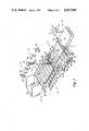
- FIG. 1illustrates the system of the preferred embodiment in a perspective view
- FIGS. 2a and 2bare plan and side views, respectively, of a portion of the facing station belt, including a portion of the robot arm;
- FIGS. 3a through 3dillustrate a method of overturning an article in the facing station of the FIG. 1 embodiment
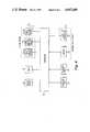
- FIG. 4is a block diagram representation useful in understanding the electrical signal interconnections of the FIG. 1 embodiment.
- the preferred embodimentincludes a singulation station 12 and a "facing" station 14, so-called because articles are manipulated there until a particular surface faces in a desired position.
- the preferred embodimentincludes a dispensing station 10 and a dispatching station 16.
- Machine vision system 22may typically include a plurality of light projectors 26a and 26b (two are shown), referred to collectively as light projectors 26, and a plurality of cameras 28a and 28b (two are shown), referred to collectively as cameras 28.
- Parcelsare conveyed from the facing station 14 to a dispatching station 16 where an operator located at work position 30 may observe a destination code on the addressee label, typically a zip code, key the code into keyboard 36 of console 34 located on cabinet 32, and the parcel is conveyed therefrom via conveyor belt system 18 to a destination in accordance with the code information.
- Console 34may typically also include displays and indicators 39 to provide instructions and status information to the operator.
- parcelsmay typically be fed into bin 20 by a conveyor belt system (not shown) while bin 20 is in a first position for receiving and retaining parcels therein.
- bin 20may be placed in a second position for dispensing parcels therefrom by the actuation of motor 38, illustratively, a stepper motor.
- motor 38operates under the control of controller 40, wherein the information relating to the number of parcels in singulation station 12 is provided to controller 40 by machine vision system 22.
- Singulation station 12comprises a plurality of cylindrical rollers 50a through 50e, referred to collectively as rollers 50; five are shown in the present example.
- the rollers 50have substantially equal cross section, and their central axes are parallel to each other and are located along a substantially horizontal plane. Rollers 50 are positioned in close proximity to the adjacent ones, but without physical contact.
- the topmost surface of the totality of rollers 50forms a support surface for the parcels.
- the cylindrical outer surfaces of rollers 50comprises a high-friction coating such as urethane rubber, so that rotational movement of rollers 50 tends to produce lateral movement of the parcels thereon.
- Singulation station 12is bounded on three sides by side walls 52 and 54 and rear wall 56, which retain parcels within singulation station 12 until they are conveyed into facing station 14.
- Side walls 52 and 54may have bottom edges formed in a scalloped pattern to conform to the contours of rollers 50, and thus reduce the likelihood of a parcel being wedged between rollers 50 and either of the side walls 52, 54.
- Parcelsare prevented from being wedged between adjacent rollers 50, between end roller 50a and rear wall 56, and between front roller 50e and facing station 14, by a shield member illustratively comprising a plurality of slats 62 which are located between adjacent rollers 50, behind end roller 50a, and in front of front roller 50e.
- Slats 62are typically fabricated of a relatively low friction material, such as stainless steel or polished aluminum, so that where contact occurs between slats 62 and a parcel, the parcel will slide easily to the adjacent roller 50.
- Slats 62are positioned in close proximity to rollers 50 without making physical contact. The plane formed by the upper surfaces of slats 62 is below the parcel support surface formed by the topmost surfaces of the rollers 50.
- Motors 64Coupled to one end of each of the rollers 50 of singulation station 12, but external to side wall 52, are a plurality of motors 64a through 64e collectively referred to as motors 64, coupled, respectively, to rollers 50a through 50e.
- Motors 64which are independently controllable by controller 40, as shown in FIG. 4, may typically be stepper motors. Alternatively, motors 64 may be independent closed-loop servo motors. Motors 64 coordinate the rotational motion of rollers 50 so as to enhance the singulation process.
- rollers 50When rollers 50 are moved together with the same rotational direction and velocity, they convey parcels thereon across singulation station 12 in a selectable direction.
- rollers 50When rollers 50 are moved individually, they separate parcels from the heap, or move a single parcel forward. In this latter case, the rotation of rollers 50 should be considered as angular displacement, to produce a specific peripheral movement, rather than running at a particular speed.
- rollers 50may not always produce singulation, i.e., isolation of a single parcel.
- the singulation processcan be assisted by the action of robot 24 guided by machine vision system 22, which directs robot 24 to push or lift on parcels to separate them. There will not always be an advantageous point for such manipulation by robot 24; rollers 50 may then be activated to agitate the heaped parcels until a point advantageous for manipulation by robot 24 appears.
- controller 40The coordination of robot 24 and rollers 50 is provided by controller 40.
- the operational area provided by rollers 50 in singulation station 12may typically have a width of 18 inches (46 cm) and a length of 30 to 36 inches (76-91 cm).
- the diameter of the rollers 50may typically assume a value of between 4 and 6 inches (10-15 cm); thus, in accordance with this example, the singulation station 12 may include between five and nine rollers 50.
- Facing station 14comprises an endless conveyor belt 90 formed in a generally triangular pattern about drive rollers 102 and 104 and idler roller 106.
- Drive rollers 102 and 104each include a plurality of longitudinal splines 120 which engage corresponding teeth formed on the inner surface 122 of belt 90.
- the outer surface 94 of belt 90includes a multiplicity of nubs 92, whose description and function are detailed in a succeeding paragraph.
- Drive rollers 102 and 104are independently driven to rotate by motors 80 and 82, respectively, which may be stepper motors. Alternatively, motors 80 and 82 may be closed-loop servo motors. When motors 80 and 82, which are controlled by controller 40, as shown in FIG. 4, cause rollers 102 and 104 to rotate in the same direction, belt 90 may be used to translate parcels across facing station 14 in a direction selectable by controller 40.
- Support 108includes a plurality of fingers 116 which mesh closely with a plurality of fingers 118 on support 110.
- parcel supports 108 and 110form a flat and relatively continuous surface under the upper region of belt 90 for supporting parcels thereon.
- Parcel supports 108 and 110may be rotated from their positions shown in FIG. 1 downward such that fingers 116, 118 are directed generally toward idler 106. Supports 108 and 110 are driven to rotate thus by parcel support motors 74 and 76, respectively, which may typically be stepper motors. The operation of motors 74 and 76 is controlled by controller 40, as shown in FIG. 4.
- the rotational axes for supports 108 and 110are virtually the same axes, respectively, as the rotational axes of drive rollers 102 and 104. Bearing arrangements which permit independent rotational motions of two devices on a common axis are well known in the art.
- Facing station 14additionally includes motor 84 having threaded shafts 86a and 86b extending axially therefrom. Threaded shaft 86a engages a correspondingly threaded portion of driver roller support 70, and oppositely-threaded shaft 86b engages a correspondingly threaded portion of drive roller support 72.
- Drive roller supports 70 and 72support drive rollers 102 and 104, respectively, and establish their longitudinal position within facing station 14. Supports 70 and 72 are slidably positioned on bearing surfaces (not shown), such that actuation of motor 84, under the control of controller 40, as shown in FIG. 4, which actuation causes rotation of threaded shafts 86a and 86b, results in movement of drive roller supports 70, 72, either toward or away from one another.
- FIGS. 2a and 2bthere are shown plan and side views, respectively, of a portion of the belt 90 used in facing station 14 of the FIG. 1 embodiment.
- Belt 90includes a plurality of nubs 92 which protrude from the upper surface 94 of belt 90.
- the lower surface 122 of belt 90includes teeth for engagement with splines 120 of driver rollers 102, 104, as shown in FIG. 1.
- Nubs 92are positioned in a regular array of rows and columns.
- Hand section 46extending from robot 24 (as shown in FIG. 1) includes a fork 96 having a plurality of tines 98, illustratively, twelve, although for ease of understanding, fewer are shown in FIGS. 1 and 2a.
- tines 98will fit between the rows of nubs 92.
- tines 98will fit between the columns of nubs 92.
- Tines 98have blunt or rounded tips 99 so that they may be used for pushing parcels with minimum likelihood of causing injury.
- Tines 98are suitably dimensioned such that they move easily between the upper surface 94 of belt 90 and a parcel supported by nubs 92.
- Belt 90may illustratively be fabricated of a molded rubber wherein nubs 92 are integrally formed into the upper surface 94 of belt 90.
- nubs 92One function of nubs 92 is that of supporting a parcel above surface 94 of belt 90 while tines 98 are slid underneath the parcel. Robot 24 may then lift the parcel and rotate it about any axis.
- a second purpose of nubs 92is to provide a multiplicity of catch points to assist in the rotation of a parcel on belt 90.
- a parcelmay be rotated by slipping the tines 98 of fork-like tool 96 under one edge of the parcel and lifting it. The opposite edge of the parcel may then tend to slide away, but it will be caught in a groove between the nubs 92, and the edge of the parcel caught in the groove becomes a fulcrum about which the parcel is rotated.
- the upper surface 94 of belt 90may have a width of 18 inches (46 cm) and a length of 24 inches (61 cm).
- the nubs 92 on belt 90may typically have a diameter of 0.25 inch (6.3 mm) and a height above surface 94 of belt 90 of 0.25 inch (6.3 mm), and have a spacing between centers of 0.50 inches (12.7 mm), along both the longitudinal and lateral dimensions.
- the tines 98 of fork 96may be 0.125 inch (3 mm) in diameter, and have a typical length of 2 inches (5.1 cm).
- FIGS. 3a through 3ddepict a sequence of events by which a relatively flat parcel 100, having an addressee label on surface 101 facing downward, may be inverted in an apparatus of the type shown as facing station 14 of the FIG. 1 embodiment.
- an endless conveyor belt 90is wrapped about drive rollers 102 and 104 and idler 106.
- Interdigitated support members 108 and 110are positioned under that portion of belt 90 between rollers 102 and 104 such that parcel 100 is supported thereon.
- rollers 102 and 104are shown as having been moved toward each other, and support members 108 and 110 have been rotated down toward idler 106, such that a downward loop 114 is formed in belt 90, into which parcel 100 falls.
- FIG. 3cdepicts counterclockwise driving motion by drive rollers 102 and 104 resulting in motion of belt 90 as shown by the arrows in the drawing.
- This belt motionin combination with the high-friction surface of belt 90, causes parcel 100 to shift from a first position leaning toward roller 102 to a second position leaning toward roller 104.
- FIG. 3dit is seen that drive rollers 102 and 104 separate back to their original positions, support members 108 and 110 rotate to their belt supporting positions, and belt 90 returns from its loop 114 with parcel 100 inverted such that surface 101 is facing upward. While illustrated with a rectangular object, rolls, limp magazines and bags are manipulated with equal facility and without damage in facing station 14.
- controller 40controls the position of bin 20 in dispensing station 10 via signals to dispensing station motor 38. It provides the independent drive signals to the plurality of roller drive motors 64a through 64e in singulation station 12, the signals which control the adjustments of the plurality of joints in robot 24, and, in facing station 14, the drive signals to the left drive motor 80 for belt 90, the right drive motor 82 for belt 90, the motor 84 for positioning drive rollers 102 and 104, and the motors 74 and 76 for positioning the interdigitated parcel supports 108 and 110, respectively.
- Controller 40additionally provides signals for controlling light projectors 26 in the machine vision system 22 and receives video information from the plurality of cameras 28 in that system 22. Finally, controller 40 interfaces with the functions provided at an operator's console 34, receiving information via keyboard 36 and sending information to indicators and displays 39 on console 34.
- controller 40may be a stored-program microprocessor having a resident program for directing the operations of the article manipulation system of FIG. 1. Controller 40 may typically be located within the cabinet 32 housing the operator's console 34.
- Robot 24, shown in the FIG. 1 embodiment as being mounted on a ceiling generally centrally above the singulation and facing stations 12, 14,may, for example, be of a type similar to the MAKER Robot System, sold by United States Robots, Carlsbad, Calif.
- the robot of the present exampleis a five-axis robot, having four rotary and one linear degrees of freedom.
- a first rotary joint 41permits robot 24 to rotate with respect to the ceiling-mounted base 42.
- a second rotary joint at shoulder 43permits arm 44 to be directed toward any point on singulation and facing stations 12, 14.
- Robot arm 44telescopes to provide a linear adjustment.
- Wrist joint 45is the third rotary joint, and hand section 46 is rotatable at rotary joint 47, the fourth rotary degree of freedom.
- the machine vision system 22 of FIG. 1is used to aid in the singulation process in singulation station 12 and aid in the manipulation process and to scan for an addressee label in facing station 14. More particularly, machine vision system 22 assesses the heap of parcels in singulation station 12, designating targets for fork-like tool 96 to push or lift for progressive singulation of parcels from the heap. It also verifies singulation of parcels in the facing station 14. If singulation has not been achieved, robot 24 is directed to singulate overlapping objects. Machine vision system 22 additionally scans parcels in the facing station 14 to locate the addressee label. It may be necessary to scan all surfaces and make a comparison before the most probable surface can be determined.
- Machine vision system 22may be implemented in any one of a number of schemes known to those skilled in the art. In general, all of these schemes employ light projecting means and one or more television cameras. The elements of the machine vision system 22 in the FIG. 1 embodiment are shown as being mounted overhead, but this configuration is not a necessary limitation on the invention.
- light projectors 26may be slide projectors of ordinary construction which project a pattern of light stripes over the area determined by the extent of singulation station 12 or facing station 14, depending on which operation is being monitored by the machine vision system 22.
- Cameras 28may be television cameras preferably utilizing solid state array sensors. Such sensors are well known to provide stable geometric precision and are widely used in machine vision applications.
- the distance between a light projector 26 and any one camera 28forms the base of a set of triangles whose sides are formed by the path of light in any specific projected stripe from projector 26, to the surface of a parcel, and then to a specific element in the array in camera 28. Since the angles are known by calibration, it is possible to determine the location of many points on the surface of the parcel, and from these points to infer the location and surface contour of the parcel.
- controller 40which is shown with its interconnections to machine vision system 22 in FIG. 4.
- machine vision system 22in conjunction with controller 40, may implement the following rules as programmed algorithms:
- the labelis on one of the two flat (large area) surfaces.
- stamps or postal meter labelsIf there is a stamp or postal meter label, it will be tagged with a fluorescent ink which will be visible under ultraviolet light. (Note: nearly all parcels with handwritten zip codes will have stamps or postal meter labels.)
- Cylindrical objects with printing at the endsare rolled newspapers. There is usually a central sleeve of manila paper with an address on it.
Landscapes
- Engineering & Computer Science (AREA)
- Mechanical Engineering (AREA)
- Control Of Conveyors (AREA)
Abstract
Description
Claims (15)
Priority Applications (1)
| Application Number | Priority Date | Filing Date | Title |
|---|---|---|---|
| US06/813,422US4697689A (en) | 1985-12-26 | 1985-12-26 | Article manipulation system |
Applications Claiming Priority (1)
| Application Number | Priority Date | Filing Date | Title |
|---|---|---|---|
| US06/813,422US4697689A (en) | 1985-12-26 | 1985-12-26 | Article manipulation system |
Publications (1)
| Publication Number | Publication Date |
|---|---|
| US4697689Atrue US4697689A (en) | 1987-10-06 |
Family
ID=25212328
Family Applications (1)
| Application Number | Title | Priority Date | Filing Date |
|---|---|---|---|
| US06/813,422Expired - Fee RelatedUS4697689A (en) | 1985-12-26 | 1985-12-26 | Article manipulation system |
Country Status (1)
| Country | Link |
|---|---|
| US (1) | US4697689A (en) |
Cited By (25)
| Publication number | Priority date | Publication date | Assignee | Title |
|---|---|---|---|---|
| US4988256A (en)* | 1987-10-22 | 1991-01-29 | General Motors Corporation | Parts assembly kitting apparatus and method |
| US5186336A (en)* | 1991-01-22 | 1993-02-16 | Electrocom Automation L.P. | Product sorting apparatus |
| US5201397A (en)* | 1990-10-05 | 1993-04-13 | Electrocom Automation L.P. | Method and apparatus for separating a stack of products into a stream of single products for sorting |
| US5203671A (en)* | 1991-07-09 | 1993-04-20 | C&D Robotics | Apparatus for palletizing bundles of paper |
| US5290100A (en)* | 1989-09-08 | 1994-03-01 | Wnc-Nitrochemie Gmbh | Method of mixing propellant charge powder rods |
| US5360316A (en)* | 1990-04-07 | 1994-11-01 | David Sarnoff Research Center, Inc. | Flats pieces singulation apparatus |
| US5605222A (en)* | 1996-04-24 | 1997-02-25 | Illinois Tool Works Inc. | Dual knife edge transfer conveyor |
| US5687831A (en)* | 1995-04-25 | 1997-11-18 | Adept Technology, Inc. | Flexible parts feeder |
| US5860504A (en)* | 1994-11-16 | 1999-01-19 | Lockheed Martin Corporation | Transfer buffer and inserter and method |
| US6056108A (en)* | 1997-11-17 | 2000-05-02 | Adept Technology, Inc. | Impulse-based, flexible parts feeder |
| US6614916B2 (en)* | 2001-01-04 | 2003-09-02 | Bell & Howell Mail And Messaging Technologies Company | Machine vision system and triggering method |
| US6662929B1 (en) | 2000-11-17 | 2003-12-16 | Lockhead Martin Corporation | Parcel singulation software control logic |
| US20050199470A1 (en)* | 2002-06-06 | 2005-09-15 | Felix Buchi | Transport of bulk material items |
| US20060083419A1 (en)* | 2004-10-18 | 2006-04-20 | Michael Carbaugh | Systems and methods for isolating parts |
| US20060151295A1 (en)* | 2004-12-27 | 2006-07-13 | Kyle Campbell | Conveyor system for minimizing product damage during collection |
| WO2007094661A1 (en)* | 2006-02-15 | 2007-08-23 | Newton Technisch Bureau B.V. | Device and method for optically scanning three-dimensional objects |
| US20080131253A1 (en)* | 2006-10-27 | 2008-06-05 | Pearson Packaging | End of Arm Tool, Apparatus, and Method of Engaging an Article |
| US20080142537A1 (en)* | 2006-12-14 | 2008-06-19 | The Coca-Cola Company | First in First Out Vending Systems |
| US20120160633A1 (en)* | 2010-12-23 | 2012-06-28 | Hon Hai Precision Industry Co., Ltd. | System and method for processing products |
| US8876100B1 (en) | 2013-09-04 | 2014-11-04 | Xerox Corporation | Robotic belt finishing system for high speed multiple card pick to sequenced stack |
| US20170166402A1 (en)* | 2015-08-25 | 2017-06-15 | Nercon Eng. & Mfg., Inc. | Micro-transfer conveyor |
| EP3575043A2 (en)* | 2018-05-09 | 2019-12-04 | Intelligrated Headquarters LLC | Method and system for manipulating items |
| US20210308722A1 (en)* | 2020-04-03 | 2021-10-07 | Material Handling Systems, Inc. | System and method for transferring parcels from a first conveyor to a second conveyor |
| US11845616B1 (en)* | 2020-08-11 | 2023-12-19 | Amazon Technologies, Inc. | Flattening and item orientation correction device |
| WO2024124594A1 (en)* | 2022-12-14 | 2024-06-20 | 启力数字科技常州有限公司 | Information acquisition device based on internet of things |
Citations (10)
| Publication number | Priority date | Publication date | Assignee | Title |
|---|---|---|---|---|
| US1962772A (en)* | 1933-11-22 | 1934-06-12 | George K Hull | Device for handling large metal plates |
| US2677452A (en)* | 1952-11-29 | 1954-05-04 | Pressed Steel Car Company Inc | Case inverter |
| US3237757A (en)* | 1963-09-03 | 1966-03-01 | Raybestos Manhattan Inc | Conveyor belt |
| US3592326A (en)* | 1969-01-31 | 1971-07-13 | Ncr Co | Parcel post singulating and orienting apparatus |
| US3840739A (en)* | 1973-08-03 | 1974-10-08 | Gerber Scientific Instr Co | Apparatus and method for tracking a raised edge without shadow interference |
| US3868024A (en)* | 1974-02-22 | 1975-02-25 | Jack C Lee | Apparatus for moving and rotating long workpieces such as structural steel |
| US4147930A (en)* | 1975-03-20 | 1979-04-03 | U.S. Philips Corporation | Object location detector |
| US4150743A (en)* | 1977-12-27 | 1979-04-24 | Burroughs Corporation | Singulation device for mail |
| US4435837A (en)* | 1981-03-05 | 1984-03-06 | President And Fellows Of Harvard College | Pattern recognition and orientation system |
| US4634328A (en)* | 1985-05-31 | 1987-01-06 | Rca Corporation | Mail singulation system |
- 1985
- 1985-12-26USUS06/813,422patent/US4697689A/ennot_activeExpired - Fee Related
Patent Citations (10)
| Publication number | Priority date | Publication date | Assignee | Title |
|---|---|---|---|---|
| US1962772A (en)* | 1933-11-22 | 1934-06-12 | George K Hull | Device for handling large metal plates |
| US2677452A (en)* | 1952-11-29 | 1954-05-04 | Pressed Steel Car Company Inc | Case inverter |
| US3237757A (en)* | 1963-09-03 | 1966-03-01 | Raybestos Manhattan Inc | Conveyor belt |
| US3592326A (en)* | 1969-01-31 | 1971-07-13 | Ncr Co | Parcel post singulating and orienting apparatus |
| US3840739A (en)* | 1973-08-03 | 1974-10-08 | Gerber Scientific Instr Co | Apparatus and method for tracking a raised edge without shadow interference |
| US3868024A (en)* | 1974-02-22 | 1975-02-25 | Jack C Lee | Apparatus for moving and rotating long workpieces such as structural steel |
| US4147930A (en)* | 1975-03-20 | 1979-04-03 | U.S. Philips Corporation | Object location detector |
| US4150743A (en)* | 1977-12-27 | 1979-04-24 | Burroughs Corporation | Singulation device for mail |
| US4435837A (en)* | 1981-03-05 | 1984-03-06 | President And Fellows Of Harvard College | Pattern recognition and orientation system |
| US4634328A (en)* | 1985-05-31 | 1987-01-06 | Rca Corporation | Mail singulation system |
Cited By (35)
| Publication number | Priority date | Publication date | Assignee | Title |
|---|---|---|---|---|
| US4988256A (en)* | 1987-10-22 | 1991-01-29 | General Motors Corporation | Parts assembly kitting apparatus and method |
| US5290100A (en)* | 1989-09-08 | 1994-03-01 | Wnc-Nitrochemie Gmbh | Method of mixing propellant charge powder rods |
| US5346304A (en)* | 1989-09-08 | 1994-09-13 | Wnc-Nitrochemie Gmbh | Apparatus for mixing propellant charge powder rods |
| US5360316A (en)* | 1990-04-07 | 1994-11-01 | David Sarnoff Research Center, Inc. | Flats pieces singulation apparatus |
| US5634562A (en)* | 1990-10-05 | 1997-06-03 | Electrocom Automation L.P. | Method and apparatus for separating, feeding and sorting |
| US5201397A (en)* | 1990-10-05 | 1993-04-13 | Electrocom Automation L.P. | Method and apparatus for separating a stack of products into a stream of single products for sorting |
| US5562195A (en)* | 1990-10-05 | 1996-10-08 | Electrocom Automation, L.P. | Method and apparatus for separating feeding and sorting |
| US5655667A (en)* | 1990-10-05 | 1997-08-12 | Electrocom Automation L.P. | Method and apparatus for separating, feeding and sorting |
| US5186336A (en)* | 1991-01-22 | 1993-02-16 | Electrocom Automation L.P. | Product sorting apparatus |
| US5203671A (en)* | 1991-07-09 | 1993-04-20 | C&D Robotics | Apparatus for palletizing bundles of paper |
| US5860504A (en)* | 1994-11-16 | 1999-01-19 | Lockheed Martin Corporation | Transfer buffer and inserter and method |
| US5687831A (en)* | 1995-04-25 | 1997-11-18 | Adept Technology, Inc. | Flexible parts feeder |
| US5605222A (en)* | 1996-04-24 | 1997-02-25 | Illinois Tool Works Inc. | Dual knife edge transfer conveyor |
| US6056108A (en)* | 1997-11-17 | 2000-05-02 | Adept Technology, Inc. | Impulse-based, flexible parts feeder |
| US6714836B2 (en) | 2000-11-17 | 2004-03-30 | Lockheed Martin Corporation | Parcel singulation software control logic |
| US6751524B2 (en) | 2000-11-17 | 2004-06-15 | Lockheed Martin Corporation | Parcel singulation software control logic |
| US6662929B1 (en) | 2000-11-17 | 2003-12-16 | Lockhead Martin Corporation | Parcel singulation software control logic |
| US6614916B2 (en)* | 2001-01-04 | 2003-09-02 | Bell & Howell Mail And Messaging Technologies Company | Machine vision system and triggering method |
| US20050199470A1 (en)* | 2002-06-06 | 2005-09-15 | Felix Buchi | Transport of bulk material items |
| US7028829B2 (en)* | 2002-06-06 | 2006-04-18 | Buechi Felix | Transport of bulk material items |
| US20060083419A1 (en)* | 2004-10-18 | 2006-04-20 | Michael Carbaugh | Systems and methods for isolating parts |
| US20060151295A1 (en)* | 2004-12-27 | 2006-07-13 | Kyle Campbell | Conveyor system for minimizing product damage during collection |
| US7287637B2 (en)* | 2004-12-27 | 2007-10-30 | Kyle Campbell | Conveyor system for minimizing product damage during collection |
| WO2007094661A1 (en)* | 2006-02-15 | 2007-08-23 | Newton Technisch Bureau B.V. | Device and method for optically scanning three-dimensional objects |
| US7717255B2 (en)* | 2006-10-27 | 2010-05-18 | Pearson Packaging Systems | End of arm tool, apparatus, and method of engaging an article |
| US20080131253A1 (en)* | 2006-10-27 | 2008-06-05 | Pearson Packaging | End of Arm Tool, Apparatus, and Method of Engaging an Article |
| US20080142537A1 (en)* | 2006-12-14 | 2008-06-19 | The Coca-Cola Company | First in First Out Vending Systems |
| US20120160633A1 (en)* | 2010-12-23 | 2012-06-28 | Hon Hai Precision Industry Co., Ltd. | System and method for processing products |
| US8876100B1 (en) | 2013-09-04 | 2014-11-04 | Xerox Corporation | Robotic belt finishing system for high speed multiple card pick to sequenced stack |
| US20170166402A1 (en)* | 2015-08-25 | 2017-06-15 | Nercon Eng. & Mfg., Inc. | Micro-transfer conveyor |
| EP3575043A2 (en)* | 2018-05-09 | 2019-12-04 | Intelligrated Headquarters LLC | Method and system for manipulating items |
| EP3575043B1 (en)* | 2018-05-09 | 2025-07-02 | Intelligrated Headquarters LLC | Method and system for manipulating items |
| US20210308722A1 (en)* | 2020-04-03 | 2021-10-07 | Material Handling Systems, Inc. | System and method for transferring parcels from a first conveyor to a second conveyor |
| US11845616B1 (en)* | 2020-08-11 | 2023-12-19 | Amazon Technologies, Inc. | Flattening and item orientation correction device |
| WO2024124594A1 (en)* | 2022-12-14 | 2024-06-20 | 启力数字科技常州有限公司 | Information acquisition device based on internet of things |
Similar Documents
| Publication | Publication Date | Title |
|---|---|---|
| US4697689A (en) | Article manipulation system | |
| US4634328A (en) | Mail singulation system | |
| US20220311480A1 (en) | Systems and methods for processing objects, including automated mobile matrix bins | |
| EP3566984B1 (en) | Method and system for manipulating articles | |
| US20230012957A1 (en) | Systems and methods for processing objects, including automated mobile matrix carriers | |
| KR102048330B1 (en) | A device for feeding items to a sorting machine and sorting machine | |
| JP3207419B2 (en) | Parcel distribution method | |
| JP7494414B2 (en) | Automatic Shipping Device | |
| CN108993906B (en) | Intelligence express delivery sorting device | |
| US5221405A (en) | Label applying system | |
| WO2004094116A1 (en) | Method and apparatus for visually indexing objects upon a moving surface | |
| AU730535B2 (en) | A process and device for emptying containers, in particular for use in mail sorting installations | |
| CA1259273A (en) | System for in-line processing of envelopes and the like | |
| US4213602A (en) | Switching device for letters and the like | |
| EP0085102B1 (en) | Transport system | |
| EP0113125A2 (en) | A detector-tilter device for arranging in a same attitude tapered bodies supplied aligned with casual attitude | |
| US4768773A (en) | Apparatus and method for the stacking and storing of workpieces | |
| US3288464A (en) | Card inverting apparatus | |
| JP7619884B2 (en) | Waste Treatment System | |
| JP2948550B2 (en) | Position / posture detection device for conveyed objects | |
| JP3003843U (en) | Work piece transfer device | |
| US3854713A (en) | Document feed mechanism | |
| JPS6121469Y2 (en) | ||
| JPH10236432A (en) | Casing system | |
| Frederick et al. | Singulation of irregular mailpieces by adaptive robotics |
Legal Events
| Date | Code | Title | Description |
|---|---|---|---|
| AS | Assignment | Owner name:RCA CORPORATION, A CORP OF DELAWARE Free format text:ASSIGNMENT OF ASSIGNORS INTEREST.;ASSIGNOR:CARRELL, ROSS M.;REEL/FRAME:004498/0595 Effective date:19851223 | |
| FEPP | Fee payment procedure | Free format text:PAYOR NUMBER ASSIGNED (ORIGINAL EVENT CODE: ASPN); ENTITY STATUS OF PATENT OWNER: LARGE ENTITY | |
| FEPP | Fee payment procedure | Free format text:PAYER NUMBER DE-ASSIGNED (ORIGINAL EVENT CODE: RMPN); ENTITY STATUS OF PATENT OWNER: LARGE ENTITY | |
| FPAY | Fee payment | Year of fee payment:4 | |
| FEPP | Fee payment procedure | Free format text:PAYOR NUMBER ASSIGNED (ORIGINAL EVENT CODE: ASPN); ENTITY STATUS OF PATENT OWNER: LARGE ENTITY | |
| AS | Assignment | Owner name:MARTIN MARIETTA CORPORATION, MARYLAND Free format text:ASSIGNMENT OF ASSIGNORS INTEREST;ASSIGNOR:GENERAL ELECTRIC COMPANY;REEL/FRAME:007046/0736 Effective date:19940322 | |
| REMI | Maintenance fee reminder mailed | ||
| LAPS | Lapse for failure to pay maintenance fees | ||
| FP | Lapsed due to failure to pay maintenance fee | Effective date:19951011 | |
| AS | Assignment | Owner name:LOCKHEED MARTIN CORPORATION, MARYLAND Free format text:ASSIGNMENT OF ASSIGNORS INTEREST;ASSIGNOR:MARTIN MARIETTA CORPORATION;REEL/FRAME:008628/0518 Effective date:19960128 | |
| STCH | Information on status: patent discontinuation | Free format text:PATENT EXPIRED DUE TO NONPAYMENT OF MAINTENANCE FEES UNDER 37 CFR 1.362 |