US4697660A - Vehicle with multiple power source - Google Patents
Vehicle with multiple power sourceDownload PDFInfo
- Publication number
- US4697660A US4697660AUS06/793,662US79366285AUS4697660AUS 4697660 AUS4697660 AUS 4697660AUS 79366285 AUS79366285 AUS 79366285AUS 4697660 AUS4697660 AUS 4697660A
- Authority
- US
- United States
- Prior art keywords
- power source
- electric motor
- multiple power
- vehicle according
- source vehicle
- Prior art date
- Legal status (The legal status is an assumption and is not a legal conclusion. Google has not performed a legal analysis and makes no representation as to the accuracy of the status listed.)
- Expired - Lifetime
Links
Images


Classifications
- B—PERFORMING OPERATIONS; TRANSPORTING
- B60—VEHICLES IN GENERAL
- B60K—ARRANGEMENT OR MOUNTING OF PROPULSION UNITS OR OF TRANSMISSIONS IN VEHICLES; ARRANGEMENT OR MOUNTING OF PLURAL DIVERSE PRIME-MOVERS IN VEHICLES; AUXILIARY DRIVES FOR VEHICLES; INSTRUMENTATION OR DASHBOARDS FOR VEHICLES; ARRANGEMENTS IN CONNECTION WITH COOLING, AIR INTAKE, GAS EXHAUST OR FUEL SUPPLY OF PROPULSION UNITS IN VEHICLES
- B60K6/00—Arrangement or mounting of plural diverse prime-movers for mutual or common propulsion, e.g. hybrid propulsion systems comprising electric motors and internal combustion engines
- B60K6/20—Arrangement or mounting of plural diverse prime-movers for mutual or common propulsion, e.g. hybrid propulsion systems comprising electric motors and internal combustion engines the prime-movers consisting of electric motors and internal combustion engines, e.g. HEVs
- B60K6/42—Arrangement or mounting of plural diverse prime-movers for mutual or common propulsion, e.g. hybrid propulsion systems comprising electric motors and internal combustion engines the prime-movers consisting of electric motors and internal combustion engines, e.g. HEVs characterised by the architecture of the hybrid electric vehicle
- B60K6/48—Parallel type
- B—PERFORMING OPERATIONS; TRANSPORTING
- B60—VEHICLES IN GENERAL
- B60K—ARRANGEMENT OR MOUNTING OF PROPULSION UNITS OR OF TRANSMISSIONS IN VEHICLES; ARRANGEMENT OR MOUNTING OF PLURAL DIVERSE PRIME-MOVERS IN VEHICLES; AUXILIARY DRIVES FOR VEHICLES; INSTRUMENTATION OR DASHBOARDS FOR VEHICLES; ARRANGEMENTS IN CONNECTION WITH COOLING, AIR INTAKE, GAS EXHAUST OR FUEL SUPPLY OF PROPULSION UNITS IN VEHICLES
- B60K1/00—Arrangement or mounting of electrical propulsion units
- Y—GENERAL TAGGING OF NEW TECHNOLOGICAL DEVELOPMENTS; GENERAL TAGGING OF CROSS-SECTIONAL TECHNOLOGIES SPANNING OVER SEVERAL SECTIONS OF THE IPC; TECHNICAL SUBJECTS COVERED BY FORMER USPC CROSS-REFERENCE ART COLLECTIONS [XRACs] AND DIGESTS
- Y02—TECHNOLOGIES OR APPLICATIONS FOR MITIGATION OR ADAPTATION AGAINST CLIMATE CHANGE
- Y02T—CLIMATE CHANGE MITIGATION TECHNOLOGIES RELATED TO TRANSPORTATION
- Y02T10/00—Road transport of goods or passengers
- Y02T10/60—Other road transportation technologies with climate change mitigation effect
- Y02T10/62—Hybrid vehicles
Definitions
- the present inventionrelates to a vehicle with multiple power source, and more particularly to a vehicle having an engine and an electric motor.
- the present inventionovercomes the disadvantages of prior electro mobile by providing a vehicle with multiple power source comprising an engine, an electric motor, a torque converter, a gear transmission, a solenoid operated clutch, a circuit controller, a starting motor, a mechanical brake, a battery, and a charger etc.
- the torque converteris disposed between the output shaft of the engine and the output shaft of the electric motor.
- the solenoid operated clutchis disposed on the output shaft of the electric motor adjacent to the torque converter for shifting power transmission between the output shaft of the engine and the output shaft of the electric motor.
- the transmissionis disposed on the output shaft of the electric motor adjacent to the solenoid operated clutch, and has an output shaft served as a wheel axle.
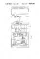
- FIG. 1is a top view of an embodiment of a vehicle with multiple power source in accordance with the present invention
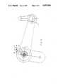
- FIG. 2is a side view of the vehicle with multiple power source of FIG. 1;
- FIG. 3is a rear view of the vehicle with multiple power source of FIG. 1;
- FIG. 4is a top view showing the solenoid operated clutch in accordance with the present invention.
- FIG. 5is a bottom view showing the solenoid operated clutch in accordance with the present invention.
- FIGS. 1-3there is shown therein a vehicle with multiple power source comprising an engine 1, an electric motor 2, a torque converter 3, a transmission 4, a solenoid operated clutch 5, a circuit controller 6, a starting motor 7, a mechanical brake 8, a battery 9, and a charger 10 etc.
- the torque converter 3is a prior known device, and also named as continuously variable transmission (CVT) and it is disposed between the output shaft 11 of the engine 1 and the output shaft 21 of the electric motor, and has two split pulleys 31.
- CVTcontinuously variable transmission
- the solenoid operated clutch 5is disposed on the output shaft 21 of the electric motor 2 adjacent to the torque converter 3.
- the solenoid operated clutch 5comprises a pair of discs 51, a solenoid valve 52, a y-shaped rod 53 which is connected to the piston rod 55 of the solenoid valve 52 by means of a connecting rod 54.
- Engagement or disengagement of the disc of the solenoid operated clutchcan be obtained by means of a ON switch and OFF switch, as well as a simple circuit, in order to control the power transmission between the output shaft 11 of the engine and the output shaft 21 of the electric motor.
- the gear transmission 4is disposed on the output shaft 21 of the electric motor adjacent to the solenoid clutch 5, and has an output shaft 41 served as a wheel axle.
- a differential 42is provided on the intermediate portion of the output shaft 41 of the transmission 4.
- the mechanical brake 8is provided on the input shaft of the transmission 4, and connected to a brake pedal 81 by means of a wire for effecting brake effect.
- circuit controller 6starting motor 7, battery 9 and charger 10 will not be described because they are all known in the art.
- the constructional principle of the torque converteris also known in the art.
- the torque converterdoes most of the efficient speed by adjusting two split pulleys in concert. For example, to shift into a higher gear, the pulley linked to the engine squeezes together, pushing the belt up to its V-shaped groove to form a bigger loop, corresponding to a larger gear. Simultaneously, the drive-shaft pulley spreads apart, dropping the belt lower in its V-groove.
- the enginealways runs at its most efficient speed by continuously adjusting the pulleys means.
- the output shaft 21 of the electric motorcan rotate smoothly because there is a bearing 22 provided between the end of output shaft 21 of the electric motor 2 and the torque converter 3 if the clutch 5 is in the "OFF" position and the switch 14 for the electric motor is "ON".
- the power of the electric motorcan be transmitted from the output shaft 21 to the wheel axle 41 via transmission 4 and differential 42.
Landscapes
- Engineering & Computer Science (AREA)
- Chemical & Material Sciences (AREA)
- Combustion & Propulsion (AREA)
- Transportation (AREA)
- Mechanical Engineering (AREA)
- Hybrid Electric Vehicles (AREA)
Abstract
Description
The present invention relates to a vehicle with multiple power source, and more particularly to a vehicle having an engine and an electric motor.
In view of the fact that the recent battery manufacturing technique can not provide a sufficient long life battery, conventional electro mobile can only supply with 2-3 hours of power source in its practical use. It is inconvenient that the electro mobile will stop in midway very often due to lack of power. Therefore, an additional break-down truck is required for drawing said electro mobile to the repair shop for charging. Furthermore, the use of the battery is impractical because it takes a long time to charge a battery. Although a spare battery can be used, it is also impractical due to the fact that the volume of the spare battery is too large and it occupied a substantical large space, with very high cost.
Briefly, the present invention overcomes the disadvantages of prior electro mobile by providing a vehicle with multiple power source comprising an engine, an electric motor, a torque converter, a gear transmission, a solenoid operated clutch, a circuit controller, a starting motor, a mechanical brake, a battery, and a charger etc. The torque converter is disposed between the output shaft of the engine and the output shaft of the electric motor. The solenoid operated clutch is disposed on the output shaft of the electric motor adjacent to the torque converter for shifting power transmission between the output shaft of the engine and the output shaft of the electric motor.
The transmission is disposed on the output shaft of the electric motor adjacent to the solenoid operated clutch, and has an output shaft served as a wheel axle.
Accordingly, it is an object of the present invention to provide a vehicle with multiple power source that can be driven by either an engine or electric motor in order that when the power source of the electric motor is exhausted, the engine can be used to avoid midway stop of the vehicle. Both engine and electric motor can be used simultaneously in order to increase the driving force of the vehicle.
Other objects and advantages of this invention will be readily apparent from the following descriptions wherein reference is made to the accompanying drawings.
FIG. 1 is a top view of an embodiment of a vehicle with multiple power source in accordance with the present invention;
FIG. 2 is a side view of the vehicle with multiple power source of FIG. 1;
FIG. 3 is a rear view of the vehicle with multiple power source of FIG. 1;
FIG. 4 is a top view showing the solenoid operated clutch in accordance with the present invention; and
FIG. 5 is a bottom view showing the solenoid operated clutch in accordance with the present invention.
Referring now to FIGS. 1-3, there is shown therein a vehicle with multiple power source comprising an engine 1, anelectric motor 2, atorque converter 3, a transmission 4, a solenoid operatedclutch 5, acircuit controller 6, astarting motor 7, amechanical brake 8, abattery 9, and a charger 10 etc. Thetorque converter 3 is a prior known device, and also named as continuously variable transmission (CVT) and it is disposed between theoutput shaft 11 of the engine 1 and theoutput shaft 21 of the electric motor, and has twosplit pulleys 31.
The solenoid operatedclutch 5 is disposed on theoutput shaft 21 of theelectric motor 2 adjacent to thetorque converter 3. Referring to FIGS. 5 and 4, the solenoid operatedclutch 5 comprises a pair ofdiscs 51, asolenoid valve 52, a y-shaped rod 53 which is connected to thepiston rod 55 of thesolenoid valve 52 by means of a connectingrod 54. Engagement or disengagement of the disc of the solenoid operated clutch can be obtained by means of a ON switch and OFF switch, as well as a simple circuit, in order to control the power transmission between theoutput shaft 11 of the engine and theoutput shaft 21 of the electric motor. The gear transmission 4 is disposed on theoutput shaft 21 of the electric motor adjacent to thesolenoid clutch 5, and has anoutput shaft 41 served as a wheel axle. Adifferential 42 is provided on the intermediate portion of theoutput shaft 41 of the transmission 4.
Themechanical brake 8 is provided on the input shaft of the transmission 4, and connected to a brake pedal 81 by means of a wire for effecting brake effect.
The constructional principle and operation of thecircuit controller 6, startingmotor 7,battery 9 and charger 10 will not be described because they are all known in the art.
The constructional principle of the torque converter is also known in the art. The torque converter does most of the efficient speed by adjusting two split pulleys in concert. For example, to shift into a higher gear, the pulley linked to the engine squeezes together, pushing the belt up to its V-shaped groove to form a bigger loop, corresponding to a larger gear. Simultaneously, the drive-shaft pulley spreads apart, dropping the belt lower in its V-groove. The engine always runs at its most efficient speed by continuously adjusting the pulleys means.
When the engine is not in operation, theoutput shaft 21 of the electric motor can rotate smoothly because there is abearing 22 provided between the end ofoutput shaft 21 of theelectric motor 2 and thetorque converter 3 if theclutch 5 is in the "OFF" position and theswitch 14 for the electric motor is "ON". The power of the electric motor can be transmitted from theoutput shaft 21 to thewheel axle 41 via transmission 4 anddifferential 42.
If the engine is to be used, depress the "ON" switch for theclutch 5 and the engine switch 13, and the power of the engine can be transmitted from the engine to thewheel axle 41 viatorque converter 3, transmission 4 anddifferential 42.
If both the engine and the electric motor are to be used simultaneously, depress the "ON" switch and theswitch 14 for the electric motor, as well as the engine switch 13. With the above said torque converter, the engine and electric motor will run synchronously in order to increase the driving force of the vehicle.
Claims (10)
1. A multiple power source vehicle comprised of:
at least two power sources;
at least two output shafts, one each of said output shafts being connected to one each of said power sources;
at least one belt-driven continuously variable torque converter; and
at least one solenoid clutch means, said belt-driven continuously variable torque converter being disposed between said two output shafts and said clutch means being disposed adjacent said belt-driven continuously variable torque converter for shifting power transmission between the output shaft of one of said power sources and the output shaft of the second of said power sources, said output shafts being connected parallel of one another.
2. A multiple power source vehicle according to claim 1 wherein said output shafts are transverse of a longitudinal axis of the vehicle.
3. A multiple power source vehicle according to claim 1 wherein there are two sources of power, the first being an electric motor and the second being an engine.
4. A multiple power source vehicle according to claim 3 wherein there are two output shafts, one of said output shafts being connected to said engine and the other of said output shaft being connected to said electric motor.
5. A multiple power source vehicle according to claim 4 wherein said output shaft of said electric motor may also serve as an intermediate drive shaft.
6. A multiple power source vehicle according to claim 2 wherein said clutch means is a solenoid clutch means.
7. A multiple power source vehicle according to claim 2 wherein said power sources operated concurrently.
8. A multiple power source vehicle according to claim 2 wherein said power sources operate asynchronously.
9. A multiple power source vehicle according to claim 4 wherein said power sources operate concurrently.
10. A multiple power source vehicle according to claim 4 wherein said power sources operate asynchronously.
Priority Applications (1)
| Application Number | Priority Date | Filing Date | Title |
|---|---|---|---|
| US06/793,662US4697660A (en) | 1985-10-31 | 1985-10-31 | Vehicle with multiple power source |
Applications Claiming Priority (1)
| Application Number | Priority Date | Filing Date | Title |
|---|---|---|---|
| US06/793,662US4697660A (en) | 1985-10-31 | 1985-10-31 | Vehicle with multiple power source |
Publications (1)
| Publication Number | Publication Date |
|---|---|
| US4697660Atrue US4697660A (en) | 1987-10-06 |
Family
ID=25160484
Family Applications (1)
| Application Number | Title | Priority Date | Filing Date |
|---|---|---|---|
| US06/793,662Expired - LifetimeUS4697660A (en) | 1985-10-31 | 1985-10-31 | Vehicle with multiple power source |
Country Status (1)
| Country | Link |
|---|---|
| US (1) | US4697660A (en) |
Cited By (31)
| Publication number | Priority date | Publication date | Assignee | Title |
|---|---|---|---|---|
| US5147003A (en)* | 1989-10-26 | 1992-09-15 | Societe Dite Sita | Composite road vehicle with electric and thermal propulsion means |
| US5176213A (en)* | 1987-12-09 | 1993-01-05 | Aisin Aw Co., Ltd. | Driving force distribution system for hybrid vehicles |
| US5251721A (en)* | 1992-04-21 | 1993-10-12 | Richard Ortenheim | Semi-hybrid electric automobile |
| US5343970A (en)* | 1992-09-21 | 1994-09-06 | Severinsky Alex J | Hybrid electric vehicle |
| FR2716843A1 (en)* | 1994-03-03 | 1995-09-08 | Guimbal Jean | Short length hybrid motor vehicle with thermal and electric motors |
| US5842534A (en)* | 1995-05-31 | 1998-12-01 | Frank; Andrew A. | Charge depletion control method and apparatus for hybrid powered vehicles |
| US5887670A (en)* | 1996-05-16 | 1999-03-30 | Toyota Jidosha Kabushiki Kaisha | Vehicle power transmitting system having devices for electrically and mechanically disconnecting power source and vehicle drive wheel upon selection of neutral state |
| US5908077A (en)* | 1995-01-30 | 1999-06-01 | Chrysler Corporation | Environmentally sensitive hybrid vehicle |
| US6116363A (en)* | 1995-05-31 | 2000-09-12 | Frank Transportation Technology, Llc | Fuel consumption control for charge depletion hybrid electric vehicles |
| US6179078B1 (en)* | 1998-05-28 | 2001-01-30 | Gregorio M. Belloso | Fuel efficient and inexpensive automobile |
| US6209672B1 (en) | 1998-09-14 | 2001-04-03 | Paice Corporation | Hybrid vehicle |
| US6338391B1 (en) | 1999-03-01 | 2002-01-15 | Paice Corporation | Hybrid vehicles incorporating turbochargers |
| US6367570B1 (en) | 1997-10-17 | 2002-04-09 | Electromotive Inc. | Hybrid electric vehicle with electric motor providing strategic power assist to load balance internal combustion engine |
| US6554088B2 (en) | 1998-09-14 | 2003-04-29 | Paice Corporation | Hybrid vehicles |
| EP1932704A2 (en) | 1998-09-14 | 2008-06-18 | Paice LLC | Hybrid vehicles |
| US20080161142A1 (en)* | 2006-12-28 | 2008-07-03 | Honda Motor Co., Ltd. | Power unit having engine and continuously variable transmission, configuration thereof, and vehicle incorporating same |
| US7641584B1 (en) | 2007-02-21 | 2010-01-05 | Belloso Gregorio M | Vehicle with primary cruiser engine and auxiliary accelerator engine |
| US20100314182A1 (en)* | 2009-06-15 | 2010-12-16 | Polaris Industries Inc. | Electric vehicle |
| EP2289750A1 (en) | 1998-09-14 | 2011-03-02 | Paice LLC | Hybrid vehicles |
| US20130168176A1 (en)* | 2011-12-28 | 2013-07-04 | Kawasaki Jukogyo Kabushiki Kaisha | Series-Hybrid Vehicle |
| US8512181B2 (en)* | 2006-11-30 | 2013-08-20 | Honda Motor Co., Ltd. | Power unit for small vehicle |
| DE10058020B4 (en)* | 2000-11-23 | 2013-09-12 | Burani Consulting Limited Liability Company | Automotive drive |
| US20140144719A1 (en)* | 2011-07-08 | 2014-05-29 | Consortium De Recherche Brp - Universite De Sherbrook S.E.N.C. | Electric off-road wheeled vehicle |
| US8960351B1 (en)* | 2013-11-27 | 2015-02-24 | Kawasaki Jukogyo Kabushiki Kaisha | Utility vehicle |
| WO2015139913A1 (en)* | 2014-03-19 | 2015-09-24 | Zf Friedrichshafen Ag | Rigid axle arrangement having an axle beam which extends in the vehicle transverse direction |
| US10668801B2 (en) | 2014-11-17 | 2020-06-02 | Alpraaz Ab | Powertrain for a vehicle |
| US10744868B2 (en) | 2016-06-14 | 2020-08-18 | Polaris Industries Inc. | Hybrid utility vehicle |
| US10780770B2 (en) | 2018-10-05 | 2020-09-22 | Polaris Industries Inc. | Hybrid utility vehicle |
| US20210323393A1 (en)* | 2018-08-14 | 2021-10-21 | Zf Friedrichshafen Ag | Drivable axle for a vehicle |
| US20220097511A1 (en)* | 2019-06-13 | 2022-03-31 | Segway Technology Co., Ltd. | Side-by-side all-terrain vehicle |
| US11370266B2 (en) | 2019-05-16 | 2022-06-28 | Polaris Industries Inc. | Hybrid utility vehicle |
Citations (6)
| Publication number | Priority date | Publication date | Assignee | Title |
|---|---|---|---|---|
| US3503464A (en)* | 1968-03-04 | 1970-03-31 | Michel N Yardney | Control system for a battery and hydrocarbon powered vehicle |
| US3858674A (en)* | 1971-10-22 | 1975-01-07 | Harry Zvi Tabor | Electric motor-flywheel drive system |
| US3923115A (en)* | 1971-10-29 | 1975-12-02 | Juergen Helling | Hybrid drive |
| US4300649A (en)* | 1978-02-07 | 1981-11-17 | Honda Giken Kogyo Kabushiki Kaisha | Engine mounting structure for vehicles |
| US4470476A (en)* | 1981-11-16 | 1984-09-11 | Hunt Hugh S | Hybrid vehicles |
| US4533011A (en)* | 1979-10-27 | 1985-08-06 | Volkswagenwerk Aktiengesellschaft | Hybrid drive for a vehicle, in particular an automobile |
- 1985
- 1985-10-31USUS06/793,662patent/US4697660A/ennot_activeExpired - Lifetime
Patent Citations (6)
| Publication number | Priority date | Publication date | Assignee | Title |
|---|---|---|---|---|
| US3503464A (en)* | 1968-03-04 | 1970-03-31 | Michel N Yardney | Control system for a battery and hydrocarbon powered vehicle |
| US3858674A (en)* | 1971-10-22 | 1975-01-07 | Harry Zvi Tabor | Electric motor-flywheel drive system |
| US3923115A (en)* | 1971-10-29 | 1975-12-02 | Juergen Helling | Hybrid drive |
| US4300649A (en)* | 1978-02-07 | 1981-11-17 | Honda Giken Kogyo Kabushiki Kaisha | Engine mounting structure for vehicles |
| US4533011A (en)* | 1979-10-27 | 1985-08-06 | Volkswagenwerk Aktiengesellschaft | Hybrid drive for a vehicle, in particular an automobile |
| US4470476A (en)* | 1981-11-16 | 1984-09-11 | Hunt Hugh S | Hybrid vehicles |
Cited By (50)
| Publication number | Priority date | Publication date | Assignee | Title |
|---|---|---|---|---|
| US5176213A (en)* | 1987-12-09 | 1993-01-05 | Aisin Aw Co., Ltd. | Driving force distribution system for hybrid vehicles |
| US5147003A (en)* | 1989-10-26 | 1992-09-15 | Societe Dite Sita | Composite road vehicle with electric and thermal propulsion means |
| US5251721A (en)* | 1992-04-21 | 1993-10-12 | Richard Ortenheim | Semi-hybrid electric automobile |
| US5343970A (en)* | 1992-09-21 | 1994-09-06 | Severinsky Alex J | Hybrid electric vehicle |
| FR2716843A1 (en)* | 1994-03-03 | 1995-09-08 | Guimbal Jean | Short length hybrid motor vehicle with thermal and electric motors |
| US5908077A (en)* | 1995-01-30 | 1999-06-01 | Chrysler Corporation | Environmentally sensitive hybrid vehicle |
| US5842534A (en)* | 1995-05-31 | 1998-12-01 | Frank; Andrew A. | Charge depletion control method and apparatus for hybrid powered vehicles |
| US6116363A (en)* | 1995-05-31 | 2000-09-12 | Frank Transportation Technology, Llc | Fuel consumption control for charge depletion hybrid electric vehicles |
| US5887670A (en)* | 1996-05-16 | 1999-03-30 | Toyota Jidosha Kabushiki Kaisha | Vehicle power transmitting system having devices for electrically and mechanically disconnecting power source and vehicle drive wheel upon selection of neutral state |
| US6367570B1 (en) | 1997-10-17 | 2002-04-09 | Electromotive Inc. | Hybrid electric vehicle with electric motor providing strategic power assist to load balance internal combustion engine |
| US6179078B1 (en)* | 1998-05-28 | 2001-01-30 | Gregorio M. Belloso | Fuel efficient and inexpensive automobile |
| EP1932704A2 (en) | 1998-09-14 | 2008-06-18 | Paice LLC | Hybrid vehicles |
| EP2289750A1 (en) | 1998-09-14 | 2011-03-02 | Paice LLC | Hybrid vehicles |
| US6554088B2 (en) | 1998-09-14 | 2003-04-29 | Paice Corporation | Hybrid vehicles |
| US7104347B2 (en) | 1998-09-14 | 2006-09-12 | Paice Llc | Hybrid vehicles |
| US7237634B2 (en) | 1998-09-14 | 2007-07-03 | Paice Llc | Hybrid vehicles |
| US6209672B1 (en) | 1998-09-14 | 2001-04-03 | Paice Corporation | Hybrid vehicle |
| US7392871B2 (en) | 1998-09-14 | 2008-07-01 | Paice Llc | Hybrid vehicles |
| US7455134B2 (en) | 1998-09-14 | 2008-11-25 | Paice Llc | Hybrid vehicles |
| US7520353B2 (en) | 1998-09-14 | 2009-04-21 | Paice Llc | Hybrid vehicle configuration |
| US7597164B2 (en) | 1998-09-14 | 2009-10-06 | Paice Llc | Hybrid vehicles |
| US6338391B1 (en) | 1999-03-01 | 2002-01-15 | Paice Corporation | Hybrid vehicles incorporating turbochargers |
| DE10058020B4 (en)* | 2000-11-23 | 2013-09-12 | Burani Consulting Limited Liability Company | Automotive drive |
| US8512181B2 (en)* | 2006-11-30 | 2013-08-20 | Honda Motor Co., Ltd. | Power unit for small vehicle |
| US8002653B2 (en)* | 2006-12-28 | 2011-08-23 | Honda Motor Co., Ltd. | Power unit having engine and continuously variable transmission, configuration thereof, and vehicle incorporating same |
| US20080161142A1 (en)* | 2006-12-28 | 2008-07-03 | Honda Motor Co., Ltd. | Power unit having engine and continuously variable transmission, configuration thereof, and vehicle incorporating same |
| US7641584B1 (en) | 2007-02-21 | 2010-01-05 | Belloso Gregorio M | Vehicle with primary cruiser engine and auxiliary accelerator engine |
| US9162558B2 (en) | 2009-06-15 | 2015-10-20 | Polaris Industries Inc. | Electric vehicle |
| US8256549B2 (en)* | 2009-06-15 | 2012-09-04 | Polaris Industries Inc. | Electric vehicle |
| US20100314182A1 (en)* | 2009-06-15 | 2010-12-16 | Polaris Industries Inc. | Electric vehicle |
| US9975425B2 (en) | 2011-07-08 | 2018-05-22 | Consortium de Recherche BRP—Universite de Sherbrooke S.E.N.C. | Electric off-road wheeled vehicle |
| US8973691B2 (en)* | 2011-07-08 | 2015-03-10 | Bombardier Recreational Products Inc. | Electric off-road wheeled vehicle |
| US9731599B2 (en) | 2011-07-08 | 2017-08-15 | Consortium de Recherche BRP—Universite de Sherbrooke S.E.N.C. | Electric off-road wheeled vehicle |
| US20140144719A1 (en)* | 2011-07-08 | 2014-05-29 | Consortium De Recherche Brp - Universite De Sherbrook S.E.N.C. | Electric off-road wheeled vehicle |
| US8662239B2 (en)* | 2011-12-28 | 2014-03-04 | Kawasaki Jukogyo Kabushiki Kaisha | Series-hybrid vehicle |
| US20130168176A1 (en)* | 2011-12-28 | 2013-07-04 | Kawasaki Jukogyo Kabushiki Kaisha | Series-Hybrid Vehicle |
| US8960351B1 (en)* | 2013-11-27 | 2015-02-24 | Kawasaki Jukogyo Kabushiki Kaisha | Utility vehicle |
| WO2015139913A1 (en)* | 2014-03-19 | 2015-09-24 | Zf Friedrichshafen Ag | Rigid axle arrangement having an axle beam which extends in the vehicle transverse direction |
| US11046168B2 (en) | 2014-11-17 | 2021-06-29 | Alpraaz Ab | Powertrain for a vehicle |
| US10668801B2 (en) | 2014-11-17 | 2020-06-02 | Alpraaz Ab | Powertrain for a vehicle |
| US10744868B2 (en) | 2016-06-14 | 2020-08-18 | Polaris Industries Inc. | Hybrid utility vehicle |
| US20210323393A1 (en)* | 2018-08-14 | 2021-10-21 | Zf Friedrichshafen Ag | Drivable axle for a vehicle |
| US11919380B2 (en)* | 2018-08-14 | 2024-03-05 | Zf Friedrichshafen Ag | Drivable axle for a vehicle |
| US10780770B2 (en) | 2018-10-05 | 2020-09-22 | Polaris Industries Inc. | Hybrid utility vehicle |
| US12420624B2 (en) | 2018-10-05 | 2025-09-23 | Polaris Industries, Inc. | Hybrid utility vehicle |
| US11370266B2 (en) | 2019-05-16 | 2022-06-28 | Polaris Industries Inc. | Hybrid utility vehicle |
| US12194808B2 (en) | 2019-05-16 | 2025-01-14 | Polaris Industries Inc. | Hybrid utility vehicle |
| US12311728B2 (en) | 2019-05-16 | 2025-05-27 | Polaris Industries Inc. | Hybrid utility vehicle |
| US20220097511A1 (en)* | 2019-06-13 | 2022-03-31 | Segway Technology Co., Ltd. | Side-by-side all-terrain vehicle |
| US11951839B2 (en)* | 2019-06-13 | 2024-04-09 | Segway Technology Co., Ltd. | Side-by-side all-terrain vehicle |
Similar Documents
| Publication | Publication Date | Title |
|---|---|---|
| US4697660A (en) | Vehicle with multiple power source | |
| US4602525A (en) | Continuously variable speed transmission for a vehicle having a forward-reverse changeover mechanism | |
| US5827146A (en) | Dual transmission for motorcycles | |
| JPH07113400B2 (en) | 2-way continuously variable transmission | |
| US7217205B2 (en) | Compact inline longitudinal CVT | |
| EP0058834A1 (en) | A continuously variable transmission for motor vehicles | |
| US4901597A (en) | Continuously variable automotive transmission | |
| US4673377A (en) | Belt-pulley type steplessly variable transmission having a reverse drive gear mechanism | |
| CN2585780Y (en) | Automatic speed variator of motor vehicle | |
| CA2013563A1 (en) | Power transmission for driving vehicle | |
| JPS6362960A (en) | Continuously variable transmission for vehicles | |
| KR20210047136A (en) | A power transmission apparatus for vehicle | |
| JPH01254424A (en) | Wheel having multiple power source | |
| KR100242063B1 (en) | Stepless Transmission for Vehicles | |
| KR100298772B1 (en) | Continuously variable transmission for vehicle | |
| KR100302770B1 (en) | Continuously variable transmission | |
| JPS58156763A (en) | Speed change gear for vehicle | |
| JPS61103055A (en) | Troidal stepless speed changer | |
| KR102554877B1 (en) | Transmission for electric vehicle | |
| KR200170887Y1 (en) | Stepless transmission for four-wheel drive vehicles | |
| KR0174200B1 (en) | Cvt for a vehicle | |
| KR0158183B1 (en) | Cvt for a vehicle | |
| KR200199617Y1 (en) | Stepless speeding changer for a vehicle | |
| KR100188141B1 (en) | Auto-transmission | |
| KR0158184B1 (en) | Cvt for a vehicle |
Legal Events
| Date | Code | Title | Description |
|---|---|---|---|
| STCF | Information on status: patent grant | Free format text:PATENTED CASE | |
| FEPP | Fee payment procedure | Free format text:PAT HLDR NO LONGER CLAIMS SMALL ENT STAT AS SMALL BUSINESS (ORIGINAL EVENT CODE: LSM2); ENTITY STATUS OF PATENT OWNER: SMALL ENTITY Free format text:PAYOR NUMBER ASSIGNED (ORIGINAL EVENT CODE: ASPN); ENTITY STATUS OF PATENT OWNER: SMALL ENTITY | |
| FPAY | Fee payment | Year of fee payment:4 | |
| FEPP | Fee payment procedure | Free format text:PAT HOLDER CLAIMS SMALL ENTITY STATUS - SMALL BUSINESS (ORIGINAL EVENT CODE: SM02); ENTITY STATUS OF PATENT OWNER: SMALL ENTITY | |
| FPAY | Fee payment | Year of fee payment:8 | |
| FPAY | Fee payment | Year of fee payment:12 |