US4695883A - Digital video compression system with variable digital filter - Google Patents
Digital video compression system with variable digital filterDownload PDFInfo
- Publication number
- US4695883A US4695883AUS06/790,869US79086985AUS4695883AUS 4695883 AUS4695883 AUS 4695883AUS 79086985 AUS79086985 AUS 79086985AUS 4695883 AUS4695883 AUS 4695883A
- Authority
- US
- United States
- Prior art keywords
- pixel
- frame
- memory
- pixel values
- stored
- Prior art date
- Legal status (The legal status is an assumption and is not a legal conclusion. Google has not performed a legal analysis and makes no representation as to the accuracy of the status listed.)
- Expired - Fee Related
Links
- 230000006835compressionEffects0.000titledescription5
- 238000007906compressionMethods0.000titledescription5
- 238000000034methodMethods0.000claimsabstractdescription18
- 230000005540biological transmissionEffects0.000claimsabstractdescription16
- 238000004891communicationMethods0.000claimsdescription12
- 230000003247decreasing effectEffects0.000claimsdescription4
- 238000012544monitoring processMethods0.000claims1
- 230000033001locomotionEffects0.000abstractdescription9
- 239000003086colorantSubstances0.000description1
- 239000002131composite materialSubstances0.000description1
- 238000010586diagramMethods0.000description1
- 230000006870functionEffects0.000description1
- 230000004048modificationEffects0.000description1
- 238000012986modificationMethods0.000description1
- 230000000717retained effectEffects0.000description1
Images


Classifications
- H—ELECTRICITY
- H04—ELECTRIC COMMUNICATION TECHNIQUE
- H04N—PICTORIAL COMMUNICATION, e.g. TELEVISION
- H04N19/00—Methods or arrangements for coding, decoding, compressing or decompressing digital video signals
- H04N19/50—Methods or arrangements for coding, decoding, compressing or decompressing digital video signals using predictive coding
- H04N19/503—Methods or arrangements for coding, decoding, compressing or decompressing digital video signals using predictive coding involving temporal prediction
- H—ELECTRICITY
- H04—ELECTRIC COMMUNICATION TECHNIQUE
- H04N—PICTORIAL COMMUNICATION, e.g. TELEVISION
- H04N11/00—Colour television systems
- H04N11/04—Colour television systems using pulse code modulation
Definitions
- This inventionrelates generally to full motion video transmission over communication channels, and more particularly to such a system which digitizes the analog video and compresses the data for transmission.
- Color television video transmissionuses a complex analog signal which is broadcast over the air.
- the video signalhas components in it that control red, green and blue "guns" located in the television receiver.
- the receiver screenis divided into a large number of points, called pixels, which the red, green and blue guns fire against.
- the intensity of the color from each gundepends upon the video signal, and when mixed at each pixel, defines the desired color for the screen at that particular point.
- the gunssweep horizontally across the screen line by line until an entire frame is completed. Normally, there are about thirty frames per second.
- the communication channelsmay be telephone lines or local area networks.
- the analog video signalcan be digitized into a digital word for each pixel.
- the digital word or numberwill have components therein to control the relative intensity of the red, green and blue guns.
- These digital numberscan be transmitted through a modem of a control computer to a receiver for display.
- These digital signalscould also be stored on a disk for playback.
- There are two fields that make up a standard video framecommonly called an odd field and an even field.
- a method and a systemfor compressing television video frames for transmission over communications channels.
- the analog signalsare digitized into color components for the pixels of the first frame.
- the digital pixel valuesare stored in a memory A.
- the pixel valuehas components representing the red, green and blue guns. These components are summed and loaded into a memory B.
- the first frameis outputted from memory A to the computer for transmission.
- the next frameis digitized and stored in memory A, replacing the previous frame pixel value.
- the color components of each pixel value of the next frameare summed.
- the difference between the sum of the pixel value from the second frame and the sum of the corresponding pixel value of the first frameis taken. If this difference exceeds a filter number which is predetermined, then the second frame pixel value from memory A is outputted to the control computer for transmission. If the difference between the sums is below the filter number, then it is not outputted through the control computer for transmission. In this manner, only the pixel values which have changed significantly will be transmitted, greatly lowering the number of bytes required for transmission or storage.
- the filterfloats. Once the frame is completed, the total number transmitted by the control computer is compared to the maximum allowable data rate. If it has exceeded the maximum allowable data rate, then the filter number is adjusted upward proportionately. If not, the filter number is adjusted downward proportionately.
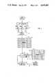
- FIG. 1is a block diagram illustrating the main components of a system constructed in accordance with this invention.
- FIG. 2is a flow chart representing the method steps of this invention.
- FIG. 3is a flow chart of the output stage compression of a system constructed in accordance with this invention.
- FIG. 4is a schematic representation of a frame with five of the pixels being transmitted to a receiver computer.
- the video source 11will be a source of analog color television video signals, such as an output from a video camera.
- the signalspass through a color converter 13, which converts the composite signal to red, green and blue components.
- the converter 13is a standard element.
- the various componentsare each fed over a separate line 15 to an analog to digital converter 17.
- the digital valuespass over data lines to an address generator 19, which stores the digital values in a memory 21, which is also referred to as memory A.
- Memory 21is schematically shown to include a large number of locations 23, each representing a pixel or point on the television screen.
- each digital number in each location 23will contain the information necessary to control the relative intensities of red, green and blue guns (not shown) of a receiver monitor.
- each digital pixel value in each location 23is a 16 bit, or two byte number. Five of the bits represent red, five of the bits represent green, and five of the bits represent blue. The remaining bit, which is the most significant or highest order bit, has a use which will be described subsequently.
- a high speed digital signal processor 25is connected to memory 21.
- DSP 25is a conventional processor, preferably a TI 32010 integrated circuit manufactured by Texas Instruments, Dallas, Texas. DSP 25 is capable of summing and subtracting functions.
- DSP 25is connected to a means for forwarding or storing the pixel values such as a control computer 27, which may be a conventional personal computer.
- Control computer 27has an internal modem for transmitting digital signals over a communication link 30, such as telephone lines, to a receiver computer 28, which includes a monitor (not shown) for displaying the picture.
- DSP 25is also linked to a memory 29, also referred to as memory B.
- Memory 29is a memory unit, similar to memory 21, having locations or cells 31. The locations 31 each hold the sum of the color components of each pixel value.
- Two registers 33 and 35are a part of the DSP 25.
- a digital counter 37also forms a part of the DSP 25.
- the first frame from the video source 11is converted to RGB components by converter 13, then converted into digital form by converter 17 and loaded into memory 21.
- the "field”is referred to herein as the "frame", even though it actually is only one half of a frame.
- the DSP 25preferably outputs the entire contents stored for the first frame to the control computer 27, as indicated by step 47.
- the control computersends the first frame over the communication link 30 to the receiver computer 28, over a time period that is sufficient for all of the bytes to be transmitted.
- Memory 21continues to hold the pixel values from the first frame.
- the DSP 25stores a selected form of the color components in memory 29.
- the DSPsums the components of each pixel value stored in memory 21.
- the intensity of each red, blue and green guncan be any number between 0 and 31, each represented by 5 bits of the 16 bit pixel value. The sum can thus be any number from 0 to 93. If, for the first pixel value, red is 14, green is 20 and blue is 10, then the sum would be 44.
- the sum of each pixel valueis loaded into consecutive locations 31 in memory 29. There will be a location 31 in memory 29 corresponding to each pixel location 23 in memory 21.
- Step 51inquires whether or not all the pixel values are loaded, and indicates that the summing continues until the entire frame is summed and loaded into memory 29.
- next frameis loaded into memory 21.
- the next frameis loaded into memory 21.
- only one field out of every other frame from the video source 11will be digitized and processed.
- the remaining frameswill not be used.
- the pixel values of this next frameare digitized and loaded into memory 21, replacing all of the original values from the first frame.
- the DSP 25then takes in step 55 the first pixel value in memory 21, sums its color components, and loads the sum into register 33. Then, as shown in step 57, the sum in register 33 is subtracted from the sum loaded in the first location 31 in memory 29. The difference, as shown by step 59, is stored in register 35. The DSP 25 converts this difference to an absolute value in step 61.
- the absolute value of the differenceis compared to a filter number in step 63.
- This filter numberis a floating number that is adjusted as will be described subsequently. If the filter number is greater than or equal to the absolute value in register 35, the counter 37 will increment to a new number, as shown in step 65.
- the DSP 25then proceeds back to step 55 to sum the next pixel value in memory 21, store the sum in register 33, and repeat the steps back to step 63.
- the DSP 25causes the counter 37 to output its current value to the control computer 27, as indicated by step 67.
- counter 37 valueis outputted in step 67, counter 37 is zeroed again.
- the number output by the counter 37represents the number of times that the value in register 35 was less than the filter number since the last time that the value in register 35 was greater than the filter number.
- This counter numberis sent to an output stage buffer in step 69. Also, each time the sum of the differences is greater than the filter, the corresponding pixel value loaded in memory 21 is outputted in step 71 to the output stage buffer 69.
- Step 75inquires whether all of the pixels are done. The summing and comparison with the sums in memory 29 takes place sequentially for an entire frame. If not completed, the DSP 25 again proceeds to step 55 to sum another pixel value from memory 21.
- step 77determines whether or not to change the value of the filter.
- the DSP 25totals the number of pixel values which were outputted from memory 21 to the output stage buffer 69. These pixel values would be the ones in which their sums differed from the sums in memory 29 by an amount greater than the filter number. All of these pixel values passing to buffer 69 will be transmitted by the control computer 27 (FIG. 1) if possible.
- the numbermay exceed the number that the communication link 30 (FIG. 1) is capable of handling in that fraction of a second. If so, control computer 27 will transmit only the pixels that the communication link 30 can handle, then it will stop.
- the total numbermight also exceed the maximum data rate for storage on a disk.
- Step 79querries whether or not it exceeded the maximum data rate for the system. In other words, if the system is capable of 56K baud, but the number of pixel values to be transmitted from that frame exceeded 56K baud, then in step 83, the filter is increased for the transmission of the next frame. If the number of pixel values to be transmitted exceeded the data rate by ten percent, the filter is increased by ten percent in step 83.
- step 85output stage compression takes place, which is shown in more detail in FIG. 3.
- the information forwarded to buffer step 69contains a 16 bit pixel value which represents the various RGB color intensities. Also, a skip count number is applied to the buffer 69.
- the skip count numberis the number of times that the counter 37 was incremented in step 65 before it was outputted and reset in step 67. This skip count locates the positions of the pixel values which will be transmitted to the receiver computer 28. For example, referring to FIG. 4, assume that there were five pixel values 84, 86, 88, 90 and 92 in a frame which were transmitted from memory 21 to the control computer 27 for transmission. These five pixel values are the pixels in which their sums differed from the sums previously stored in memory 29 by a value greater than the filter number.
- the compressed picture to be transmittedwill be as follows:
- the receiver computer 28will output a new color for pixel value 84, which is the fourth pixel in the frame. It will retain and display the old pixel values for the next 40 pixels. Then it will output a pixel value for pixel value 86.
- the numbers 34, 31, and 4represent the spaces between pixel values 86 and 88, 88 and 90, and 90 and 92 respectively. These numbers are the skip counts, and they indicate the number of unchanged pixels between the new colors.
- the pixel values 84, 86, 88, 90, and 92will be 15 bit binary words, with five bits assigned to each red, green and blue color. The data is thus compressed, since in the example only five pixel values are being sent, rather than all of the pixel values.
- the datais further compressed in the output stage.
- the buffer 69holds the output data before final compression.
- the start frame byteis read in step 87 and output to the control computer 27 in step 89.
- the control computerreads in step 91 the skip count. There are enough pixels in the frame such that the count could take 2 bytes to represent. However, an inquiry is made whether or not the skip count is less than 128 in step 93. If the skip count is less than 128, then it takes only 1 byte to portray that number and only a single byte skip count is transmitted by control computer 27. The second byte, which would be all zeros, is not transmitted by control computer 27 as indicated in step 99.
- a two byte skip countis transmitted by the control computer 27 in step 97.
- the most significant bit of the two byte skip countis set to 1 in step 95.
- the most significant bitis the first bit, which would represent 2 to the sixteenth power. If it is set to 1, this will indicate to the receiver computer 28 that the skip count is a two byte number. It will thus know that the second byte following deals with the skip count, and not with a pixel value.
- step 101the two byte pixel value is read by the control computer 27. There will always be a two byte pixel value, but the MSB (most significant bit) is not required to depict pixel values, since only 15 bits are required for the RGB components.
- step 105the two byte count for the next pixel is read by the control computer 27. As indicated by the lines on the left side of the flow chart of FIG. 3, data from buffer 69 is read as needed in steps 87, 91, 101, and 105.
- step 107an inquiry is made whether or not the skip count read in step 105 is zero. If not, in step 109, the first pixel value is outputted to the control computer 27 for transmission without further modification. If it is zero, this indicates that two pixels are being updated next to each other.
- the MSB of the first pixel valueis set to 1, as indicated by step 111.
- the pixel valueis outputted to the control computer 27, with its MSB set to 1. In this case, the control computer 27 will not output any skip count for the immediately following pixel.
- step 115indicates a return back to box 53 to digitize the next frame into memory 21.
- the receiver computer 28could store the information for later playback or display the picture simultaneously. To display, the digital pixel values are converted to analog and used to control the RGB guns. The pixel values which are not updated are retained by the receiver computer 28 and converted to analog to become a part of the signal containing the updated pixel values.
- the inventionhas significant advantages. Real motion is isolated and separated from noise and other variations by deriving the sum of the color components. This value indicates the overall brightness of a particular pixel on the screen, which changes significantly with motion, but very little with background noise. The best possible picture quality is provided given the amount of true motion by using the floating filter and the maximum allowable data rate.
- the filterindicates the degree of brightness change necessary before the device determines that a new pixel value is required. Since a given data rate will allow only a limited number of new pixels to be changed for each frame, the filter constantly changes to decide which ones should be transmitted. When motion is extreme, for example, people walking in front of the camera, the filter is floated very high so that only the most intense brightness changes are specified.
- the floating filteralso allows the device to adapt to a wide variety of maximum available data rates. For example, at 56K baud, the filter might float at values of ten to fifty, while at 1000K baud, it might float at lower numbers of three to eight.
- the final compression stagefuther reduces the amount of data by sending only one byte when the skip count is less than 128, and by sending no skip count bytes when the skip count is zero.
Landscapes
- Engineering & Computer Science (AREA)
- Multimedia (AREA)
- Signal Processing (AREA)
- Color Television Systems (AREA)
Abstract
Description
Claims (20)
Priority Applications (4)
| Application Number | Priority Date | Filing Date | Title |
|---|---|---|---|
| US06/790,869US4695883A (en) | 1985-10-24 | 1985-10-24 | Digital video compression system with variable digital filter |
| CA000521251ACA1265234A (en) | 1985-10-24 | 1986-10-23 | Digital video compression system |
| EP86308304AEP0221743A3 (en) | 1985-10-24 | 1986-10-24 | Method and system for compressing video signals |
| JP61252150AJPS62116088A (en) | 1985-10-24 | 1986-10-24 | Digital video compacting system |
Applications Claiming Priority (1)
| Application Number | Priority Date | Filing Date | Title |
|---|---|---|---|
| US06/790,869US4695883A (en) | 1985-10-24 | 1985-10-24 | Digital video compression system with variable digital filter |
Publications (1)
| Publication Number | Publication Date |
|---|---|
| US4695883Atrue US4695883A (en) | 1987-09-22 |
Family
ID=25151978
Family Applications (1)
| Application Number | Title | Priority Date | Filing Date |
|---|---|---|---|
| US06/790,869Expired - Fee RelatedUS4695883A (en) | 1985-10-24 | 1985-10-24 | Digital video compression system with variable digital filter |
Country Status (4)
| Country | Link |
|---|---|
| US (1) | US4695883A (en) |
| EP (1) | EP0221743A3 (en) |
| JP (1) | JPS62116088A (en) |
| CA (1) | CA1265234A (en) |
Cited By (12)
| Publication number | Priority date | Publication date | Assignee | Title |
|---|---|---|---|---|
| US4935953A (en)* | 1989-04-27 | 1990-06-19 | International Business Machines Corporation | Cyclic video region transmission for videoconferencing systems |
| US5063444A (en)* | 1990-03-19 | 1991-11-05 | At&T Bell Laboratories | High definition television arrangement with signal selections adapted to the available transmission capacity |
| US5872572A (en)* | 1995-12-08 | 1999-02-16 | International Business Machines Corporation | Method and apparatus for generating non-uniform resolution image data |
| US20010034770A1 (en)* | 2000-04-21 | 2001-10-25 | O'brien Terry | Method and device for implementing networked terminals in graphical operating environment |
| US6628708B1 (en)* | 2000-02-25 | 2003-09-30 | International Business Machines Corporation | Method and system for compressing color video data within a data processing system |
| EP1292151A3 (en)* | 2001-09-07 | 2004-03-10 | Alcatel | Method for compressing moving images |
| US20080137751A1 (en)* | 1998-12-21 | 2008-06-12 | Kendyl Allen Roman | Separate plane compression using plurality of compression methods including ZLN and ZLD methods |
| US20090046776A1 (en)* | 2007-08-17 | 2009-02-19 | The Hong Kong University Of Science And Technology | Efficient temporal search range control for video encoding processes |
| US7673321B2 (en) | 1991-01-07 | 2010-03-02 | Paul Yurt | Audio and video transmission and receiving system |
| US20140292631A1 (en)* | 2011-12-19 | 2014-10-02 | Maximino Vasquez | Backlight modulation over external display interfaces to save power |
| US20170301057A1 (en)* | 2012-09-06 | 2017-10-19 | Imagination Technologies Limited | Systems and Methods of Partial Frame Buffer Updating |
| US10893229B1 (en)* | 2019-09-30 | 2021-01-12 | Amazon Technologies, Inc. | Dynamic pixel rate-based video |
Families Citing this family (3)
| Publication number | Priority date | Publication date | Assignee | Title |
|---|---|---|---|---|
| US4888638A (en)* | 1988-10-11 | 1989-12-19 | A. C. Nielsen Company | System for substituting television programs transmitted via telephone lines |
| ES2038897B1 (en)* | 1991-06-07 | 1995-10-16 | Alcatel Espacio Sa | DATA OUTPUT SPEED REGULATION METHOD AND DEVICE FOR VARIABLE OUTPUT SPEED IMAGE COMPRESSORS. |
| US5335017A (en)* | 1993-01-08 | 1994-08-02 | Scott C. Harris | Method for encoding transmitting and receiving high definition television signals using single variable independent equations representing each pixel over time |
Citations (4)
| Publication number | Priority date | Publication date | Assignee | Title |
|---|---|---|---|---|
| US4025950A (en)* | 1976-05-27 | 1977-05-24 | The United States Of America As Represented By The Administrator Of The National Aeronautics And Space Administration | Sampling video compression system |
| US4302775A (en)* | 1978-12-15 | 1981-11-24 | Compression Labs, Inc. | Digital video compression system and methods utilizing scene adaptive coding with rate buffer feedback |
| US4455571A (en)* | 1981-03-10 | 1984-06-19 | Victor Company Of Japan, Ltd. | Compression system and compression and expansion system for a composite video signal |
| US4517596A (en)* | 1981-09-29 | 1985-05-14 | Nippon Electric Co., Ltd. | System comprising a preliminary processing device controlled in accordance with an amount of information stored in a buffer |
Family Cites Families (4)
| Publication number | Priority date | Publication date | Assignee | Title |
|---|---|---|---|---|
| CA1042097A (en)* | 1974-10-21 | 1978-11-07 | Nippon Telegraph And Telephone Public Corporation | Interframe coding system with automatic control of magnitude of interframe difference signal |
| FR2343384A1 (en)* | 1976-03-01 | 1977-09-30 | Lannionnais Electronique | Colour TV signal transmission equipment - includes A:D converter using PCM signal with corresponding ROM and D:A converter at receiver |
| US4402010A (en)* | 1981-07-10 | 1983-08-30 | Vvs Energy Patent Fund, Inc. | Digital television signal processing and transmission system |
| DE3202783A1 (en)* | 1982-01-28 | 1983-08-04 | Volker 2067 Reinfeld Wraase | Method for transmitting colour pictures |
- 1985
- 1985-10-24USUS06/790,869patent/US4695883A/ennot_activeExpired - Fee Related
- 1986
- 1986-10-23CACA000521251Apatent/CA1265234A/ennot_activeExpired - Fee Related
- 1986-10-24EPEP86308304Apatent/EP0221743A3/ennot_activeWithdrawn
- 1986-10-24JPJP61252150Apatent/JPS62116088A/enactivePending
Patent Citations (4)
| Publication number | Priority date | Publication date | Assignee | Title |
|---|---|---|---|---|
| US4025950A (en)* | 1976-05-27 | 1977-05-24 | The United States Of America As Represented By The Administrator Of The National Aeronautics And Space Administration | Sampling video compression system |
| US4302775A (en)* | 1978-12-15 | 1981-11-24 | Compression Labs, Inc. | Digital video compression system and methods utilizing scene adaptive coding with rate buffer feedback |
| US4455571A (en)* | 1981-03-10 | 1984-06-19 | Victor Company Of Japan, Ltd. | Compression system and compression and expansion system for a composite video signal |
| US4517596A (en)* | 1981-09-29 | 1985-05-14 | Nippon Electric Co., Ltd. | System comprising a preliminary processing device controlled in accordance with an amount of information stored in a buffer |
Cited By (18)
| Publication number | Priority date | Publication date | Assignee | Title |
|---|---|---|---|---|
| US4935953A (en)* | 1989-04-27 | 1990-06-19 | International Business Machines Corporation | Cyclic video region transmission for videoconferencing systems |
| US5063444A (en)* | 1990-03-19 | 1991-11-05 | At&T Bell Laboratories | High definition television arrangement with signal selections adapted to the available transmission capacity |
| US7673321B2 (en) | 1991-01-07 | 2010-03-02 | Paul Yurt | Audio and video transmission and receiving system |
| US7818773B2 (en) | 1991-01-07 | 2010-10-19 | Acacia Media Technologies Corporation | Audio and video transmission and receiving system |
| US7730512B2 (en) | 1991-01-07 | 2010-06-01 | Acacia Media Technologies Corporation | Audio and video transmission and receiving system |
| US5872572A (en)* | 1995-12-08 | 1999-02-16 | International Business Machines Corporation | Method and apparatus for generating non-uniform resolution image data |
| US8416847B2 (en)* | 1998-12-21 | 2013-04-09 | Zin Stai Pte. In, Llc | Separate plane compression using plurality of compression methods including ZLN and ZLD methods |
| US20080137751A1 (en)* | 1998-12-21 | 2008-06-12 | Kendyl Allen Roman | Separate plane compression using plurality of compression methods including ZLN and ZLD methods |
| US6628708B1 (en)* | 2000-02-25 | 2003-09-30 | International Business Machines Corporation | Method and system for compressing color video data within a data processing system |
| US20010034770A1 (en)* | 2000-04-21 | 2001-10-25 | O'brien Terry | Method and device for implementing networked terminals in graphical operating environment |
| EP1292151A3 (en)* | 2001-09-07 | 2004-03-10 | Alcatel | Method for compressing moving images |
| US20090046776A1 (en)* | 2007-08-17 | 2009-02-19 | The Hong Kong University Of Science And Technology | Efficient temporal search range control for video encoding processes |
| US8731048B2 (en)* | 2007-08-17 | 2014-05-20 | Tsai Sheng Group Llc | Efficient temporal search range control for video encoding processes |
| US20140292631A1 (en)* | 2011-12-19 | 2014-10-02 | Maximino Vasquez | Backlight modulation over external display interfaces to save power |
| US9524681B2 (en)* | 2011-12-19 | 2016-12-20 | Intel Corporation | Backlight modulation over external display interfaces to save power |
| US20170301057A1 (en)* | 2012-09-06 | 2017-10-19 | Imagination Technologies Limited | Systems and Methods of Partial Frame Buffer Updating |
| US9990692B2 (en)* | 2012-09-06 | 2018-06-05 | Imagination Technologies Limited | Systems and methods of partial frame buffer updating |
| US10893229B1 (en)* | 2019-09-30 | 2021-01-12 | Amazon Technologies, Inc. | Dynamic pixel rate-based video |
Also Published As
| Publication number | Publication date |
|---|---|
| CA1265234A (en) | 1990-01-30 |
| EP0221743A3 (en) | 1987-09-16 |
| EP0221743A2 (en) | 1987-05-13 |
| JPS62116088A (en) | 1987-05-27 |
Similar Documents
| Publication | Publication Date | Title |
|---|---|---|
| US4695883A (en) | Digital video compression system with variable digital filter | |
| US4816901A (en) | Method and system for compressing color video data | |
| US5047853A (en) | Method for compresssing and decompressing color video data that uses luminance partitioning | |
| US4541012A (en) | Video bandwidth reduction system employing interframe block differencing and transform domain coding | |
| CA1125907A (en) | Picture signal coding apparatus | |
| EP0527245A1 (en) | Method and system for coding and compressing video signals | |
| US6738087B2 (en) | Method and system for transferring live video pictures from a video camera to a remote video displayer via a conventional telephone line | |
| US4694336A (en) | Digital data transmission method | |
| US5589884A (en) | Adaptive quantization controlled by scene change detection | |
| EP0300775B1 (en) | Signal encoding and decoding method and device | |
| US5519790A (en) | Method for reducing noise in digital video information | |
| EP0846397B1 (en) | Video processing method with compression | |
| US4849807A (en) | Method and system for compressing color video feature encoded data | |
| US4217574A (en) | Analog to digital converter having nonlinear amplitude transformation | |
| EP0960525B1 (en) | Method of chroma-keying for a digital video compression system | |
| US6317515B1 (en) | Method and apparatus for encoding and decoding a data stream using inferential techniques | |
| US4684983A (en) | Non-linear processor for reducing the dynamic range of a digitized error signal | |
| US5862412A (en) | Apparatus for converting document data into bit map data and compressing display image formed by combining the bit map data and image data | |
| US6674897B1 (en) | Picture data compression device and red data detection device | |
| CA2131420C (en) | Red data detector for picture data compression device | |
| US5448296A (en) | Variable parameter block coding and data compression system | |
| US4271431A (en) | Scan converter utilizing discrete differentially coded signals | |
| EP0339938B1 (en) | Method and system for compressing colour video encoded data | |
| EP0339947A2 (en) | Method and system for decompressing colour video encoded data | |
| JPS5821985A (en) | Transmitting and displaying system of picture information |
Legal Events
| Date | Code | Title | Description |
|---|---|---|---|
| AS | Assignment | Owner name:MICRO SERVICES, INC., 1116 SUMMER STREET SUITE 2A, Free format text:ASSIGNMENT OF ASSIGNORS INTEREST.;ASSIGNORS:CHANDLER, VAN S.;ARNSTEIN, ROBERT A.;REEL/FRAME:004544/0457 Effective date:19860429 Owner name:MICRO SERVICES, INC., A CORP OF CONNECTICUT,CONN Free format text:ASSIGNMENT OF ASSIGNORS INTEREST;ASSIGNORS:CHANDLER, VAN S.;ARNSTEIN, ROBERT A.;REEL/FRAME:004544/0457 Effective date:19860429 | |
| AS | Assignment | Owner name:CONCEPT COMMUNICATIONS, INC., 45 CHURCH ST., STAMF Free format text:ASSIGNMENT OF ASSIGNORS INTEREST.;ASSIGNOR:MICRO SERVICES, INC., A CT CORP.;REEL/FRAME:004722/0350 Effective date:19870526 | |
| AS | Assignment | Owner name:CONCEPT COMMUNICATIONS, INC., 1950 STEMMONS FREEWA Free format text:ASSIGNMENT OF ASSIGNORS INTEREST.;ASSIGNOR:CONCEPTS COMMUNICATIONS, INC., A DE CORP;REEL/FRAME:004929/0411 Effective date:19880811 Owner name:CONCEPT COMMUNICATIONS, INC., A CORP OF TEXAS, TEX Free format text:ASSIGNMENT OF ASSIGNORS INTEREST;ASSIGNOR:CONCEPTS COMMUNICATIONS, INC., A DE CORP;REEL/FRAME:004929/0411 Effective date:19880811 | |
| FPAY | Fee payment | Year of fee payment:4 | |
| SULP | Surcharge for late payment | ||
| AS | Assignment | Owner name:BOLTER COMMUNICATIONS, INC., TEXAS Free format text:ORDER AUTHORIZING SALE OF PROPERTY FREE AND CLEAR OF ALL INTERESTS PURSUANT TO 11 U.S.C. 363(B) AND (F);ASSIGNORS:SHERMAN, DANIEL J.;CHAPTER 7 TRUSTEE FOR CONCEPT COMMUNICATIONS, INC.;REEL/FRAME:006412/0516 Effective date:19921221 Owner name:BOLTER COMMUNICATIONS, INC., TEXAS Free format text:ASSIGNMENT OF ASSIGNORS INTEREST.;ASSIGNOR:BANKRUPTCY TRUSTEE FOR CONCEPT COMMUNICATIONS, INC.;REEL/FRAME:006412/0513 Effective date:19930113 | |
| REMI | Maintenance fee reminder mailed | ||
| LAPS | Lapse for failure to pay maintenance fees | ||
| FP | Lapsed due to failure to pay maintenance fee | Effective date:19950927 | |
| STCH | Information on status: patent discontinuation | Free format text:PATENT EXPIRED DUE TO NONPAYMENT OF MAINTENANCE FEES UNDER 37 CFR 1.362 |