US4695161A - Automatic ranging gun sight - Google Patents
Automatic ranging gun sightDownload PDFInfo
- Publication number
- US4695161A US4695161AUS06/637,721US63772184AUS4695161AUS 4695161 AUS4695161 AUS 4695161AUS 63772184 AUS63772184 AUS 63772184AUS 4695161 AUS4695161 AUS 4695161A
- Authority
- US
- United States
- Prior art keywords
- target
- weapon
- projectile
- housing
- hair
- Prior art date
- Legal status (The legal status is an assumption and is not a legal conclusion. Google has not performed a legal analysis and makes no representation as to the accuracy of the status listed.)
- Expired - Fee Related
Links
- 230000003287optical effectEffects0.000claimsabstractdescription8
- 239000004973liquid crystal related substanceSubstances0.000claimsabstractdescription7
- 230000008685targetingEffects0.000description5
- 238000000034methodMethods0.000description4
- 238000010586diagramMethods0.000description2
- 230000003213activating effectEffects0.000description1
- 230000003028elevating effectEffects0.000description1
- 230000005484gravityEffects0.000description1
- 238000005259measurementMethods0.000description1
- 238000010297mechanical methods and processMethods0.000description1
- 238000012986modificationMethods0.000description1
- 230000004048modificationEffects0.000description1
- 230000008707rearrangementEffects0.000description1
- 230000004044responseEffects0.000description1
- 238000006467substitution reactionMethods0.000description1
Images

Classifications
- F—MECHANICAL ENGINEERING; LIGHTING; HEATING; WEAPONS; BLASTING
- F41—WEAPONS
- F41G—WEAPON SIGHTS; AIMING
- F41G3/00—Aiming or laying means
- F41G3/06—Aiming or laying means with rangefinder
- G—PHYSICS
- G02—OPTICS
- G02B—OPTICAL ELEMENTS, SYSTEMS OR APPARATUS
- G02B23/00—Telescopes, e.g. binoculars; Periscopes; Instruments for viewing the inside of hollow bodies; Viewfinders; Optical aiming or sighting devices
- G02B23/14—Viewfinders
- G—PHYSICS
- G02—OPTICS
- G02B—OPTICAL ELEMENTS, SYSTEMS OR APPARATUS
- G02B27/00—Optical systems or apparatus not provided for by any of the groups G02B1/00 - G02B26/00, G02B30/00
- G02B27/32—Fiducial marks and measuring scales within the optical system
- G02B27/36—Fiducial marks and measuring scales within the optical system adjustable
Definitions
- the present inventionpertains to a targeting apparatus for a weapon and in particular to a rifle sight which provides automatic compensation for range.
- a weapon such as a rifleis typically aimed at long distances by use of a telescopic sight.
- a sightincludes horizontal and vertical cross-hairs to provide aiming of the rifle toward the target. It is well known that if the target is located at greater distances from the rifle, the rifle angle above horizontal must be increased to compensate for the vertical drop by the projectile during its flight from the rifle to the target.
- a selected embodiment of the present inventioncomprises an automatic ranging sight for a weapon which fires a projectile.
- the sightincludes means for determining the distance from the weapon to a target.
- An optical vieweris mounted on the weapon for viewing the target.
- a reticle within the viewerprovides horizontal cross-hair positions which are selectable over a vertical range.
- Electronic circuitryis provided for selecting one of the horizontal cross-hair positions as a function of the distance to the target and a parameter associated with the travel of the projectile whereby the selected cross-hair position provides elevation aiming to the target for the weapon.
- FIG. 1is a schematic diagram for the automatic ranging sight of the present invention
- FIG. 2is an illustration of a reticle having a plurality of liquid crystal display horizontal lines which serve as horizontal cross-hairs,
- FIG. 3is an illustration of a reticle having a plurality of vertical liquid crystal display lines which serve as selectable vertical cross-hairs in addition to the horizontal cross-hairs,
- FIG. 4is a cut-away plan view of an automatic ranging sight in accordance with the present invention.
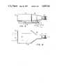
- FIG. 5is an elevation view of the sight shown in FIG. 4, and
- FIG. 6is a plan view of the sight shown in FIG. 4.
- the auto-ranging system shown in FIG. 1is generally referred to by the reference numeral 10.
- the system 10can be mounted on a weapon (not shown) such as a rifle.
- the weaponfires projectiles at a selected target.
- the system 10includes an optical viewing scope 12 which is essentially aligned with the bore of the weapon.
- the operator of the weaponviews the target through the scope 12.
- the scope 12further includes a reticle 14 which is further described in reference to FIGS. 2 and 3.
- the reticle 14is electrically activated through a group of lines 16.
- a microprocessor 18generates control signals which are transmitted through the lines 16 to the reticle 14.
- a keyboard 20is connected through lines 22 for providing control information to the microprocessor 18.
- a radar horn 28transmits and receives radar pulses which are reflected from a target.
- the radar range informationis transmitted through a line 30 to a distance measuring circuit 32.
- the circuit 32determines the distance from the system 10 to the target which reflects the radar pulses.
- the distance information to the targetis transmitted through a line 34 to the microprocessor 18.
- the reticle 14is shown in FIG. 2.
- the reticle 14is preferably a liquid crystal display (LCD).
- the reticle 14includes a fixed vertical line 38 which serves as a vertical cross-hair. The line 38 is visible at all times.
- the reticle 14further includes a plurality of horizontal lines 40, each of which consists of a thin strip extending across the reticle. Each of the lines 40 can be selectively activated while the non-activated lines are essentially invisible.
- a line 40ais shown activated.
- the lines 40are selectively activated in response to commands received from the microprocessor 18 (shown in FIG. 1) through lines 16 which are connected respectively to the lines 40.
- FIG. 3shows a variation of the reticle 14 which further includes a group of liquid crystal lines 42 which represent vertical cross-hairs.
- the vertical lines 42are also connected to the lines 16 from microprocessor 18 (shown in FIG 1).
- the optional vertical lines 42provide a windage compensation for targeting the system 10.
- the lines 42like the lines 40, are essentially transparent except when a selected one of the lines, such as 42a, is activated.
- System 50is an integral unit which can be mounted on many types of weapons, typically rifles, in the same manner as a conventional telescopic sight.
- the system 50includes a scope 52 having lenses 54 and 56 and prisms 58 and 60.
- the scope 52further includes a reticle 62 which corresponds to the reticle 14 previously described.
- a radar horn 64is connected to a circuit board 66 which has circuitry mounted thereon to provide distance measuring for radar pulses transmitted and received by horn 64.
- the circuit board 66is connected through a cable 68 to the reticle 62.
- the scope 52, horn 64, circuit board 66 and cable 68are included in a housing 70.
- FIGS. 5 and 6there are illustrated elevation and plan views of the system 50 as it is mounted on a rifle 76.
- the system 50is connected to rifle 76 through adjustable mounts 78 and 80.
- Mount 78includes an adjustment screw 78a for providing vertical adjustment of the system 50 relative to the rifle 76.
- the adjustable mount 80includes a horizontal track for providing horizontal movement of the system 50 relative to the rifle 76.
- the mounts 78 and 80provide basic alignment and aiming of the system 50 with respect to the rifle 76.
- FIG. 6there is further shown a cover 82 which provides access to within the housing 70. By opening the cover 82 the operator has access to the keyboard 20 (shown in FIG. 1) for entering required information. There is further shown in FIG. 6 the radar pulses that are transmitted and received by horn 64 and the line of sight for the scope 52.
- the selected elevationis provided by activating one of a plurality of horizontal cross-hairs within the lines 40 of the reticle 14.
- the selected cross-hairis determined by the microprocessor 18.
- the determination of the selected horizontal cross-hairis a function of the distance from the system 10 to the target and the flight path of the projectile.
- the most significant element of the projectile flight pathis its velocity. Higher velocity projectiles have a lesser drop for a given distance than do lower velocity projectiles.
- the velocity of a projectile which is used with the system 10is enter via the keyboard 20 into the microprocessor 18.
- Other informationsuch as air resistance of the projectile, can also be entered into the microprocessor 18 if such information is significant for the targeting of the projectile.
- Other relative informationcan be the type and condition of the particular weapon being used with the projectile.
- the microprocessor 18utilizes the distance measurement provided by the circuit 32 together with the parameter information describing the flight of the projectile. Based upon this information the microprocessor 18 selects one of the horizontal cross-hairs in the lines 40 to provide the desired elevation for the weapon which is aimed by the system 10. The operator then aligns the desired target within the vertical and horizontal cross-hairs so that the projectile can be directed accurately to the target.
- the reticle 14can be provided with windage compensation as illustrated in FIG. 3.
- the windage compensationcan be entered via the keyboard 20 as with the projectile parameters or it may be entered manually with an external switch (not shown) which is connected to the vertical lines 42.
- the windage informationcan be input automatically by a wind sensor system (not shown).
- the operator of the weaponcan be provided automatically with the necessary targeting information for aiming the weapon such that there is a high probability that the projectile will strike the target.
- the radar horn 28, and associated radar systemcan be replaced with a laser range finder such as shown in U.S. Pat. No. 3,533,696.
- the laser range finderprovides the distance measuring function just as described for the radar system above.
- DMDdistance measuring devices
- Application of the present inventionis not limited to a hand-held weapon, such as a rifle. It can also be utilized in the targeting of a heavy weapon, such as the main gun of a tank.
Landscapes
- Physics & Mathematics (AREA)
- General Physics & Mathematics (AREA)
- Optics & Photonics (AREA)
- Engineering & Computer Science (AREA)
- General Engineering & Computer Science (AREA)
- Astronomy & Astrophysics (AREA)
- Aiming, Guidance, Guns With A Light Source, Armor, Camouflage, And Targets (AREA)
Abstract
Description
Claims (2)
Priority Applications (1)
| Application Number | Priority Date | Filing Date | Title |
|---|---|---|---|
| US06/637,721US4695161A (en) | 1984-08-06 | 1984-08-06 | Automatic ranging gun sight |
Applications Claiming Priority (1)
| Application Number | Priority Date | Filing Date | Title |
|---|---|---|---|
| US06/637,721US4695161A (en) | 1984-08-06 | 1984-08-06 | Automatic ranging gun sight |
Publications (1)
| Publication Number | Publication Date |
|---|---|
| US4695161Atrue US4695161A (en) | 1987-09-22 |
Family
ID=24557111
Family Applications (1)
| Application Number | Title | Priority Date | Filing Date |
|---|---|---|---|
| US06/637,721Expired - Fee RelatedUS4695161A (en) | 1984-08-06 | 1984-08-06 | Automatic ranging gun sight |
Country Status (1)
| Country | Link |
|---|---|
| US (1) | US4695161A (en) |
Cited By (72)
| Publication number | Priority date | Publication date | Assignee | Title |
|---|---|---|---|---|
| EP0357845A1 (en)* | 1987-04-29 | 1990-03-14 | Varo, Inc. | Solid state reticle projector for a weapon sight |
| US4965439A (en)* | 1982-09-24 | 1990-10-23 | Moore Sidney D | Microcontroller-controlled device for surveying, rangefinding and trajectory compensation |
| US4993833A (en)* | 1987-10-09 | 1991-02-19 | Kontron Elektronik Gmbh | Weapon aiming device |
| FR2656078A1 (en)* | 1989-12-20 | 1991-06-21 | France Etat Armement | SCOPE FOR COMBAT VEHICLE. |
| US5127165A (en)* | 1989-09-12 | 1992-07-07 | Polzin David H | Lead computing sight |
| FR2677133A1 (en)* | 1991-05-28 | 1992-12-04 | Coudert Anne Marie | Device for the detection and remote destruction of explosive mines and missiles |
| US5180881A (en)* | 1991-06-12 | 1993-01-19 | Electronics & Space Corp. | Beam steered laser for fire control |
| US5194908A (en)* | 1991-11-29 | 1993-03-16 | Computing Devices Canada Ltd. | Detecting target movement |
| WO1993020399A1 (en)* | 1992-03-31 | 1993-10-14 | Alliant Techsystems Inc. | Laser rangefinder optical sight (lros) |
| US5373482A (en)* | 1990-02-26 | 1994-12-13 | Trend Tec Inc. | Distance measuring system arranged to limit false indications of distance measurements |
| US5555662A (en)* | 1993-06-08 | 1996-09-17 | Teetzel; James W. | Laser range finding apparatus |
| US5669174A (en)* | 1993-06-08 | 1997-09-23 | Teetzel; James W. | Laser range finding apparatus |
| US5824942A (en)* | 1996-01-22 | 1998-10-20 | Raytheon Company | Method and device for fire control of a high apogee trajectory weapon |
| FR2769698A1 (en)* | 1997-10-09 | 1999-04-16 | Israel Atomic Energy Comm | SHOOTING CONTROL METHOD AND APPARATUS |
| US6269581B1 (en)* | 1999-04-12 | 2001-08-07 | John Groh | Range compensating rifle scope |
| US6516551B2 (en)* | 2000-12-27 | 2003-02-11 | American Technologies Network Corporation | Optical sight with switchable reticle |
| US20040020099A1 (en)* | 2001-03-13 | 2004-02-05 | Osborn John H. | Method and apparatus to provide precision aiming assistance to a shooter |
| US20040057121A1 (en)* | 2002-06-17 | 2004-03-25 | International Technologies (Lasers) Ltd. | Auxiliary optical unit attachable to optical devices, particularly telescopic gun sights |
| US20040231220A1 (en)* | 2003-05-23 | 2004-11-25 | Mccormick Patrick | Trajectory compensating riflescope |
| US20050021282A1 (en)* | 1997-12-08 | 2005-01-27 | Sammut Dennis J. | Apparatus and method for calculating aiming point information |
| US20050057808A1 (en)* | 2003-09-12 | 2005-03-17 | Lasermax, Inc. | Diffractive head up display for firearms |
| US20050088729A1 (en)* | 2001-06-19 | 2005-04-28 | Edwards Ralph C. | Modular scope |
| WO2005015285A3 (en)* | 2003-08-12 | 2005-04-28 | Elop Electrooptics Ind Ltd | System for projecting a reticle for an aiming device |
| US20050198885A1 (en)* | 2004-03-10 | 2005-09-15 | Raytheon Company | Weapon sight having multi-munitions ballistics computer |
| US20050241207A1 (en)* | 2004-03-10 | 2005-11-03 | Raytheon Company, A Corporation Of The State Of Delaware | Common aperture time-division-multiplexed laser rangefinder |
| US20050241209A1 (en)* | 2004-03-10 | 2005-11-03 | Raytheon Company A Corporation Of The State Of Delaware | Device with multiple sights for respective different munitions |
| US20050252062A1 (en)* | 2004-05-12 | 2005-11-17 | Scrogin Andrew D | Infrared range-finding and compensating scope for use with a projectile firing device |
| WO2005124389A1 (en)* | 2004-06-15 | 2005-12-29 | In-Kyu Park | Electronic distance measuring apparatus |
| US20060010761A1 (en)* | 2004-03-10 | 2006-01-19 | Raytheon Company A Corporation Of The State Of Delaware | Weapon sight having analog on-target indicators |
| USD516156S1 (en) | 2005-03-25 | 2006-02-28 | Crandall Paul E | Range determining rifle scope |
| US20060048432A1 (en)* | 2004-03-10 | 2006-03-09 | Raytheon Company, A Corporation Of The State Of Delaware | Weapon sight with ballistics information persistence |
| US20060272194A1 (en)* | 2005-02-08 | 2006-12-07 | Arnold Guettner | Firearm for low velocity projectiles |
| US20070044364A1 (en)* | 1997-12-08 | 2007-03-01 | Horus Vision | Apparatus and method for calculating aiming point information |
| US20070234626A1 (en)* | 2005-08-29 | 2007-10-11 | Murdock Steven G | Systems and methods for adjusting a sighting device |
| WO2008060319A3 (en)* | 2006-03-27 | 2008-11-27 | Horus Vision Llc | Apparatus and method for calculating aiming point information |
| AU2004205102B2 (en)* | 1997-12-08 | 2009-04-02 | Horus Vision, Llc | Apparatus and method for calculating aiming point information for rifle scopes |
| US7703679B1 (en) | 2006-02-03 | 2010-04-27 | Burris Corporation | Trajectory compensating sighting device systems and methods |
| US20100301116A1 (en)* | 2006-02-03 | 2010-12-02 | Burris Company | Trajectory compensating sighting device systems and methods |
| US20110132983A1 (en)* | 2009-05-15 | 2011-06-09 | Horus Vision Llc | Apparatus and method for calculating aiming point information |
| US7966763B1 (en) | 2008-05-22 | 2011-06-28 | The United States Of America As Represented By The Secretary Of The Navy | Targeting system for a projectile launcher |
| US8051597B1 (en)* | 2007-06-14 | 2011-11-08 | Cubic Corporation | Scout sniper observation scope |
| US20120137567A1 (en)* | 1997-12-08 | 2012-06-07 | Horus Vision Llc | Apparatus and method for aiming point calculation |
| US20120145786A1 (en)* | 2010-12-07 | 2012-06-14 | Bae Systems Controls, Inc. | Weapons system and targeting method |
| US20120159833A1 (en)* | 2009-07-08 | 2012-06-28 | Gs Development Ab | Fire-control system |
| US20120233901A1 (en)* | 2009-04-24 | 2012-09-20 | In Woo Kim | Firearm having dual barrels |
| US8701330B2 (en) | 2011-01-01 | 2014-04-22 | G. David Tubb | Ballistic effect compensating reticle and aim compensation method |
| US20140166751A1 (en)* | 2011-01-19 | 2014-06-19 | Horus Vision Llc | Apparatus and method for calculating aiming point information |
| CN103925840A (en)* | 2014-04-27 | 2014-07-16 | 李颖 | Infrared ray and ultrasonic wave mixed sighting device |
| US8833655B2 (en) | 2011-05-26 | 2014-09-16 | Burris Corporation | Magnification compensating sighting systems and methods |
| US8893423B2 (en) | 2011-05-27 | 2014-11-25 | G. David Tubb | Dynamic targeting system with projectile-specific aiming indicia in a reticle and method for estimating ballistic effects of changing environment and ammunition |
| US8959824B2 (en) | 2012-01-10 | 2015-02-24 | Horus Vision, Llc | Apparatus and method for calculating aiming point information |
| US9038901B2 (en) | 2012-02-15 | 2015-05-26 | Burris Company, Inc. | Optical device having windage measurement instruments |
| US9091507B2 (en) | 2012-02-04 | 2015-07-28 | Burris Company | Optical device having projected aiming point |
| US9121672B2 (en) | 2011-01-01 | 2015-09-01 | G. David Tubb | Ballistic effect compensating reticle and aim compensation method with sloped mil and MOA wind dot lines |
| US9250036B2 (en) | 2012-03-05 | 2016-02-02 | Burris Company, Inc. | Optical device utilizing ballistic zoom and methods for sighting a target |
| US20180172404A1 (en)* | 2015-01-20 | 2018-06-21 | Leupold & Stevens, Inc. | Real-time ballistic solutions for calculating an aiming adjustment and for indicating a subsonic threshold |
| US10132593B2 (en) | 2014-11-26 | 2018-11-20 | Burris Corporation | Multi-turn elevation knob for optical device |
| US10180565B2 (en) | 2017-02-06 | 2019-01-15 | Sheltered Wings, Inc. | Viewing optic with an integrated display system |
| WO2019038476A1 (en)* | 2017-08-23 | 2019-02-28 | Beneq Oy | Sight display device and method for manufacturing sight display device |
| US10254082B2 (en) | 2013-01-11 | 2019-04-09 | Hvrt Corp. | Apparatus and method for calculating aiming point information |
| US10415934B2 (en) | 2015-02-27 | 2019-09-17 | Burris Company, Inc. | Self-aligning optical sight mount |
| US10415933B1 (en) | 2015-01-20 | 2019-09-17 | Leupold & Stevens, Inc. | Real-time ballistic solutions for moving-target aiming calculations |
| US10534166B2 (en) | 2016-09-22 | 2020-01-14 | Lightforce Usa, Inc. | Optical targeting information projection system |
| US10823532B2 (en) | 2018-09-04 | 2020-11-03 | Hvrt Corp. | Reticles, methods of use and manufacture |
| US11287638B2 (en) | 2019-08-20 | 2022-03-29 | Francesco E. DeAngelis | Reflex sight with superluminescent micro-display, dynamic reticle, and metadata overlay |
| US11473873B2 (en) | 2019-01-18 | 2022-10-18 | Sheltered Wings, Inc. | Viewing optic with round counter system |
| US11480411B2 (en) | 2011-01-01 | 2022-10-25 | G. David Tubb | Range-finding and compensating scope with ballistic effect compensating reticle, aim compensation method and adaptive method for compensating for variations in ammunition or variations in atmospheric conditions |
| US11480781B2 (en) | 2018-04-20 | 2022-10-25 | Sheltered Wings, Inc. | Viewing optic with direct active reticle targeting |
| US11592266B2 (en)* | 2019-12-11 | 2023-02-28 | Dimitri Mikroulis | Firearm magnifier, system and method |
| US11675180B2 (en) | 2018-01-12 | 2023-06-13 | Sheltered Wings, Inc. | Viewing optic with an integrated display system |
| US11966038B2 (en) | 2018-03-20 | 2024-04-23 | Sheltered Wings, Inc. | Viewing optic with a base having a light module |
| US11994364B2 (en) | 2018-08-08 | 2024-05-28 | Sheltered Wings, Inc. | Display system for a viewing optic |
Citations (3)
| Publication number | Priority date | Publication date | Assignee | Title |
|---|---|---|---|---|
| US3464770A (en)* | 1964-11-07 | 1969-09-02 | Leitz Ernst Gmbh | Combined sighting mechanism and laser range finder |
| US3885861A (en)* | 1972-10-02 | 1975-05-27 | Hughes Aircraft Co | Liquid crystal digital reticle |
| US4404890A (en)* | 1978-11-02 | 1983-09-20 | Barr & Stroud Limited | Fire control system |
- 1984
- 1984-08-06USUS06/637,721patent/US4695161A/ennot_activeExpired - Fee Related
Patent Citations (3)
| Publication number | Priority date | Publication date | Assignee | Title |
|---|---|---|---|---|
| US3464770A (en)* | 1964-11-07 | 1969-09-02 | Leitz Ernst Gmbh | Combined sighting mechanism and laser range finder |
| US3885861A (en)* | 1972-10-02 | 1975-05-27 | Hughes Aircraft Co | Liquid crystal digital reticle |
| US4404890A (en)* | 1978-11-02 | 1983-09-20 | Barr & Stroud Limited | Fire control system |
Cited By (161)
| Publication number | Priority date | Publication date | Assignee | Title |
|---|---|---|---|---|
| US4965439A (en)* | 1982-09-24 | 1990-10-23 | Moore Sidney D | Microcontroller-controlled device for surveying, rangefinding and trajectory compensation |
| EP0357845A1 (en)* | 1987-04-29 | 1990-03-14 | Varo, Inc. | Solid state reticle projector for a weapon sight |
| US4993833A (en)* | 1987-10-09 | 1991-02-19 | Kontron Elektronik Gmbh | Weapon aiming device |
| US5127165A (en)* | 1989-09-12 | 1992-07-07 | Polzin David H | Lead computing sight |
| FR2656078A1 (en)* | 1989-12-20 | 1991-06-21 | France Etat Armement | SCOPE FOR COMBAT VEHICLE. |
| US5373482A (en)* | 1990-02-26 | 1994-12-13 | Trend Tec Inc. | Distance measuring system arranged to limit false indications of distance measurements |
| FR2677133A1 (en)* | 1991-05-28 | 1992-12-04 | Coudert Anne Marie | Device for the detection and remote destruction of explosive mines and missiles |
| US5180881A (en)* | 1991-06-12 | 1993-01-19 | Electronics & Space Corp. | Beam steered laser for fire control |
| US5194908A (en)* | 1991-11-29 | 1993-03-16 | Computing Devices Canada Ltd. | Detecting target movement |
| WO1993020399A1 (en)* | 1992-03-31 | 1993-10-14 | Alliant Techsystems Inc. | Laser rangefinder optical sight (lros) |
| US5555662A (en)* | 1993-06-08 | 1996-09-17 | Teetzel; James W. | Laser range finding apparatus |
| US5669174A (en)* | 1993-06-08 | 1997-09-23 | Teetzel; James W. | Laser range finding apparatus |
| US5824942A (en)* | 1996-01-22 | 1998-10-20 | Raytheon Company | Method and device for fire control of a high apogee trajectory weapon |
| FR2769698A1 (en)* | 1997-10-09 | 1999-04-16 | Israel Atomic Energy Comm | SHOOTING CONTROL METHOD AND APPARATUS |
| US6247259B1 (en)* | 1997-10-09 | 2001-06-19 | The State Of Israel, Atomic Energy Commission, Soreq Nuclear Research Center | Method and apparatus for fire control |
| US8707608B2 (en)* | 1997-12-08 | 2014-04-29 | Horus Vision Llc | Apparatus and method for calculating aiming point information |
| US8230635B2 (en)* | 1997-12-08 | 2012-07-31 | Horus Vision Llc | Apparatus and method for calculating aiming point information |
| AU2004205102B2 (en)* | 1997-12-08 | 2009-04-02 | Horus Vision, Llc | Apparatus and method for calculating aiming point information for rifle scopes |
| AU2004205102B8 (en)* | 1997-12-08 | 2009-07-23 | Horus Vision, Llc | Apparatus and method for calculating aiming point information for rifle scopes |
| US8966806B2 (en) | 1997-12-08 | 2015-03-03 | Horus Vision, Llc | Apparatus and method for calculating aiming point information |
| US20070044364A1 (en)* | 1997-12-08 | 2007-03-01 | Horus Vision | Apparatus and method for calculating aiming point information |
| US20050021282A1 (en)* | 1997-12-08 | 2005-01-27 | Sammut Dennis J. | Apparatus and method for calculating aiming point information |
| US9068794B1 (en) | 1997-12-08 | 2015-06-30 | Horus Vision, Llc; | Apparatus and method for aiming point calculation |
| US20090235570A1 (en)* | 1997-12-08 | 2009-09-24 | Horus Vision | Apparatus and method for calculating aiming point information |
| US8656630B2 (en)* | 1997-12-08 | 2014-02-25 | Horus Vision Llc | Apparatus and method for aiming point calculation |
| US9335123B2 (en) | 1997-12-08 | 2016-05-10 | Horus Vision, Llc | Apparatus and method for aiming point calculation |
| US7832137B2 (en) | 1997-12-08 | 2010-11-16 | Horus Vision, Llc | Apparatus and method for calculating aiming point information |
| US20120137567A1 (en)* | 1997-12-08 | 2012-06-07 | Horus Vision Llc | Apparatus and method for aiming point calculation |
| US8109029B1 (en)* | 1997-12-08 | 2012-02-07 | Horus Vision, Llc | Apparatus and method for calculating aiming point information |
| US7937878B2 (en)* | 1997-12-08 | 2011-05-10 | Horus Vision Llc | Apparatus and method for calculating aiming point information |
| US20110089238A1 (en)* | 1997-12-08 | 2011-04-21 | Horus Vision Llc | Apparatus and Method for Calculating Aiming Point Information |
| US7856750B2 (en) | 1997-12-08 | 2010-12-28 | Horus Vision Llc | Apparatus and method for calculating aiming point information |
| US6269581B1 (en)* | 1999-04-12 | 2001-08-07 | John Groh | Range compensating rifle scope |
| US6516551B2 (en)* | 2000-12-27 | 2003-02-11 | American Technologies Network Corporation | Optical sight with switchable reticle |
| US20040020099A1 (en)* | 2001-03-13 | 2004-02-05 | Osborn John H. | Method and apparatus to provide precision aiming assistance to a shooter |
| US20050088729A1 (en)* | 2001-06-19 | 2005-04-28 | Edwards Ralph C. | Modular scope |
| US6819495B2 (en) | 2002-06-17 | 2004-11-16 | International Technologies (Lasers) Ltd. | Auxiliary optical unit attachable to optical devices, particularly telescopic gun sights |
| US20040057121A1 (en)* | 2002-06-17 | 2004-03-25 | International Technologies (Lasers) Ltd. | Auxiliary optical unit attachable to optical devices, particularly telescopic gun sights |
| US20040231220A1 (en)* | 2003-05-23 | 2004-11-25 | Mccormick Patrick | Trajectory compensating riflescope |
| WO2005015285A3 (en)* | 2003-08-12 | 2005-04-28 | Elop Electrooptics Ind Ltd | System for projecting a reticle for an aiming device |
| US20050057808A1 (en)* | 2003-09-12 | 2005-03-17 | Lasermax, Inc. | Diffractive head up display for firearms |
| US20080062487A1 (en)* | 2003-09-12 | 2008-03-13 | Lasermax, Inc. | Head up display for firearms |
| US7721481B2 (en) | 2003-09-12 | 2010-05-25 | Lasermax, Inc. | Head up display for firearms |
| US7069685B2 (en)* | 2003-09-12 | 2006-07-04 | Lasermax, Inc. | Diffractive head up display for firearms |
| US20080098640A1 (en)* | 2003-11-12 | 2008-05-01 | Sammut Dennis J | Apparatus And Method For Calculating Aiming Point Information |
| WO2005047805A3 (en)* | 2003-11-12 | 2007-08-16 | Horus Vision Llc | Apparatus and method for calculating aiming point information |
| US9459077B2 (en) | 2003-11-12 | 2016-10-04 | Hvrt Corp. | Apparatus and method for calculating aiming point information |
| US9869530B2 (en) | 2003-11-12 | 2018-01-16 | Hvrt Corp. | Apparatus and method for calculating aiming point information |
| US10295307B2 (en) | 2003-11-12 | 2019-05-21 | Hvrt Corp. | Apparatus and method for calculating aiming point information |
| US10731948B2 (en) | 2003-11-12 | 2020-08-04 | Hvrt Corp. | Apparatus and method for calculating aiming point information |
| EP1690060A4 (en)* | 2003-11-12 | 2010-07-14 | Horus Vision Llc | Apparatus and method for calculating aiming point information |
| US20060010761A1 (en)* | 2004-03-10 | 2006-01-19 | Raytheon Company A Corporation Of The State Of Delaware | Weapon sight having analog on-target indicators |
| US7490430B2 (en) | 2004-03-10 | 2009-02-17 | Raytheon Company | Device with multiple sights for respective different munitions |
| US7269920B2 (en) | 2004-03-10 | 2007-09-18 | Raytheon Company | Weapon sight with ballistics information persistence |
| US20060048432A1 (en)* | 2004-03-10 | 2006-03-09 | Raytheon Company, A Corporation Of The State Of Delaware | Weapon sight with ballistics information persistence |
| US8375620B2 (en) | 2004-03-10 | 2013-02-19 | Raytheon Company | Weapon sight having multi-munitions ballistics computer |
| US20050198885A1 (en)* | 2004-03-10 | 2005-09-15 | Raytheon Company | Weapon sight having multi-munitions ballistics computer |
| US20050241207A1 (en)* | 2004-03-10 | 2005-11-03 | Raytheon Company, A Corporation Of The State Of Delaware | Common aperture time-division-multiplexed laser rangefinder |
| US7171776B2 (en)* | 2004-03-10 | 2007-02-06 | Raytheon Company | Weapon sight having analog on-target indicators |
| US20050241209A1 (en)* | 2004-03-10 | 2005-11-03 | Raytheon Company A Corporation Of The State Of Delaware | Device with multiple sights for respective different munitions |
| US8056281B2 (en) | 2004-03-10 | 2011-11-15 | Raytheon Company | Device with multiple sights for respective different munitions |
| US20050252062A1 (en)* | 2004-05-12 | 2005-11-17 | Scrogin Andrew D | Infrared range-finding and compensating scope for use with a projectile firing device |
| US7516571B2 (en) | 2004-05-12 | 2009-04-14 | Scrogin Andrew D | Infrared range-finding and compensating scope for use with a projectile firing device |
| US20070177155A1 (en)* | 2004-06-15 | 2007-08-02 | Park In-Kyu | Electronic distance measuring apparatus |
| US7372771B2 (en) | 2004-06-15 | 2008-05-13 | Park In-Kyu | Electronic distance measuring apparatus |
| WO2005124389A1 (en)* | 2004-06-15 | 2005-12-29 | In-Kyu Park | Electronic distance measuring apparatus |
| US20060272194A1 (en)* | 2005-02-08 | 2006-12-07 | Arnold Guettner | Firearm for low velocity projectiles |
| USD516156S1 (en) | 2005-03-25 | 2006-02-28 | Crandall Paul E | Range determining rifle scope |
| US20070234626A1 (en)* | 2005-08-29 | 2007-10-11 | Murdock Steven G | Systems and methods for adjusting a sighting device |
| US7703679B1 (en) | 2006-02-03 | 2010-04-27 | Burris Corporation | Trajectory compensating sighting device systems and methods |
| US20100301116A1 (en)* | 2006-02-03 | 2010-12-02 | Burris Company | Trajectory compensating sighting device systems and methods |
| US8201741B2 (en) | 2006-02-03 | 2012-06-19 | Burris Corporation | Trajectory compensating sighting device systems and methods |
| WO2008060319A3 (en)* | 2006-03-27 | 2008-11-27 | Horus Vision Llc | Apparatus and method for calculating aiming point information |
| EP2008049A4 (en)* | 2006-03-27 | 2010-07-14 | Horus Vision Llc | Apparatus and method for calculating aiming point information |
| US8051597B1 (en)* | 2007-06-14 | 2011-11-08 | Cubic Corporation | Scout sniper observation scope |
| US8209897B2 (en) | 2008-05-22 | 2012-07-03 | The United States Of America As Represented By The Secretary Of The Navy | Targeting system for a projectile launcher |
| US7966763B1 (en) | 2008-05-22 | 2011-06-28 | The United States Of America As Represented By The Secretary Of The Navy | Targeting system for a projectile launcher |
| US20120233901A1 (en)* | 2009-04-24 | 2012-09-20 | In Woo Kim | Firearm having dual barrels |
| US8887615B2 (en)* | 2009-04-24 | 2014-11-18 | Agency For Defense Development | Firearm having dual barrels |
| US8893971B1 (en) | 2009-05-15 | 2014-11-25 | Horus Vision, Llc | Apparatus and method for calculating aiming point information |
| US9250038B2 (en) | 2009-05-15 | 2016-02-02 | Horus Vision, Llc | Apparatus and method for calculating aiming point information |
| US9574850B2 (en) | 2009-05-15 | 2017-02-21 | Hvrt Corp. | Apparatus and method for calculating aiming point information |
| US8905307B2 (en) | 2009-05-15 | 2014-12-09 | Horus Vision Llc | Apparatus and method for calculating aiming point information |
| US11421961B2 (en) | 2009-05-15 | 2022-08-23 | Hvrt Corp. | Apparatus and method for calculating aiming point information |
| US10060703B2 (en) | 2009-05-15 | 2018-08-28 | Hvrt Corp. | Apparatus and method for calculating aiming point information |
| US8991702B1 (en) | 2009-05-15 | 2015-03-31 | Horus Vision, Llc | Apparatus and method for calculating aiming point information |
| US10948265B2 (en) | 2009-05-15 | 2021-03-16 | Hvrt Corp. | Apparatus and method for calculating aiming point information |
| US8353454B2 (en) | 2009-05-15 | 2013-01-15 | Horus Vision, Llc | Apparatus and method for calculating aiming point information |
| US20110132983A1 (en)* | 2009-05-15 | 2011-06-09 | Horus Vision Llc | Apparatus and method for calculating aiming point information |
| US10502529B2 (en) | 2009-05-15 | 2019-12-10 | Hvrt Corp. | Apparatus and method for calculating aiming point information |
| US20120159833A1 (en)* | 2009-07-08 | 2012-06-28 | Gs Development Ab | Fire-control system |
| US9115956B2 (en)* | 2009-07-08 | 2015-08-25 | Gs Development Ab | Fire-control system |
| US8245623B2 (en)* | 2010-12-07 | 2012-08-21 | Bae Systems Controls Inc. | Weapons system and targeting method |
| US20120145786A1 (en)* | 2010-12-07 | 2012-06-14 | Bae Systems Controls, Inc. | Weapons system and targeting method |
| US9581415B2 (en) | 2011-01-01 | 2017-02-28 | G. David Tubb | Ballistic effect compensating reticle and aim compensation method |
| US8701330B2 (en) | 2011-01-01 | 2014-04-22 | G. David Tubb | Ballistic effect compensating reticle and aim compensation method |
| US10371485B2 (en) | 2011-01-01 | 2019-08-06 | G. David Tubb | Reticle and ballistic effect compensation method having gyroscopic precession compensated wind dots |
| US9557142B2 (en) | 2011-01-01 | 2017-01-31 | G. David Tubb | Ballistic effect compensating reticle and aim compensation method with leveling reference and spin-drift compensated wind dots |
| US9121672B2 (en) | 2011-01-01 | 2015-09-01 | G. David Tubb | Ballistic effect compensating reticle and aim compensation method with sloped mil and MOA wind dot lines |
| US10180307B2 (en) | 2011-01-01 | 2019-01-15 | G. David Tubb | Ballistic effect compensating reticle, aim compensation method and adaptive method for compensating for variations in ammunition or variations in atmospheric conditions |
| US11480411B2 (en) | 2011-01-01 | 2022-10-25 | G. David Tubb | Range-finding and compensating scope with ballistic effect compensating reticle, aim compensation method and adaptive method for compensating for variations in ammunition or variations in atmospheric conditions |
| US20140166751A1 (en)* | 2011-01-19 | 2014-06-19 | Horus Vision Llc | Apparatus and method for calculating aiming point information |
| US8833655B2 (en) | 2011-05-26 | 2014-09-16 | Burris Corporation | Magnification compensating sighting systems and methods |
| US9482516B2 (en) | 2011-05-26 | 2016-11-01 | Burris Corporation | Magnification compensating sighting systems and methods |
| US8893423B2 (en) | 2011-05-27 | 2014-11-25 | G. David Tubb | Dynamic targeting system with projectile-specific aiming indicia in a reticle and method for estimating ballistic effects of changing environment and ammunition |
| US9175927B2 (en) | 2011-05-27 | 2015-11-03 | G. David Tubb | Dynamic targeting system with projectile-specific aiming indicia in a reticle and method for estimating ballistic effects of changing environment and ammunition |
| US10488153B2 (en) | 2012-01-10 | 2019-11-26 | Hvrt Corp. | Apparatus and method for calculating aiming point information |
| US11391542B2 (en) | 2012-01-10 | 2022-07-19 | Hvrt Corp. | Apparatus and method for calculating aiming point information |
| US10488154B2 (en) | 2012-01-10 | 2019-11-26 | Hvrt Corp. | Apparatus and method for calculating aiming point information |
| US10451385B2 (en) | 2012-01-10 | 2019-10-22 | Hvrt Corp. | Apparatus and method for calculating aiming point information |
| US8959824B2 (en) | 2012-01-10 | 2015-02-24 | Horus Vision, Llc | Apparatus and method for calculating aiming point information |
| US20240418479A1 (en)* | 2012-01-10 | 2024-12-19 | Hvrt Corp. | Apparatus and method for calculating aiming point information |
| US11965711B2 (en) | 2012-01-10 | 2024-04-23 | Hvrt Corp. | Apparatus and method for calculating aiming point information |
| US11181342B2 (en) | 2012-01-10 | 2021-11-23 | Hvrt Corp. | Apparatus and method for calculating aiming point information |
| US9612086B2 (en)* | 2012-01-10 | 2017-04-04 | Hvrt Corp. | Apparatus and method for calculating aiming point information |
| US9255771B2 (en) | 2012-01-10 | 2016-02-09 | Horus Vision Llc | Apparatus and method for calculating aiming point information |
| US9091507B2 (en) | 2012-02-04 | 2015-07-28 | Burris Company | Optical device having projected aiming point |
| US10145652B2 (en) | 2012-02-04 | 2018-12-04 | Burris Company, Inc. | Optical device having projected aiming point |
| US9038901B2 (en) | 2012-02-15 | 2015-05-26 | Burris Company, Inc. | Optical device having windage measurement instruments |
| US9689643B2 (en) | 2012-03-05 | 2017-06-27 | Burris Company, Inc. | Optical device utilizing ballistic zoom and methods for sighting a target |
| US9250036B2 (en) | 2012-03-05 | 2016-02-02 | Burris Company, Inc. | Optical device utilizing ballistic zoom and methods for sighting a target |
| US10458753B2 (en) | 2013-01-11 | 2019-10-29 | Hvrt Corp. | Apparatus and method for calculating aiming point information |
| US10895434B2 (en) | 2013-01-11 | 2021-01-19 | Hvrt Corp. | Apparatus and method for calculating aiming point information |
| US11656060B2 (en) | 2013-01-11 | 2023-05-23 | Hvrt Corp. | Apparatus and method for calculating aiming point information |
| US11255640B2 (en) | 2013-01-11 | 2022-02-22 | Hvrt Corp. | Apparatus and method for calculating aiming point information |
| US10254082B2 (en) | 2013-01-11 | 2019-04-09 | Hvrt Corp. | Apparatus and method for calculating aiming point information |
| CN103925840A (en)* | 2014-04-27 | 2014-07-16 | 李颖 | Infrared ray and ultrasonic wave mixed sighting device |
| CN103925840B (en)* | 2014-04-27 | 2016-08-24 | 席雅南 | Infrared ray and ultrasound wave mixing sighting device |
| US10132593B2 (en) | 2014-11-26 | 2018-11-20 | Burris Corporation | Multi-turn elevation knob for optical device |
| US10502527B2 (en)* | 2015-01-20 | 2019-12-10 | Leupold & Stevens, Inc. | Real-time ballistic solutions for calculating an aiming adjustment and for indicating a subsonic threshold |
| US10415933B1 (en) | 2015-01-20 | 2019-09-17 | Leupold & Stevens, Inc. | Real-time ballistic solutions for moving-target aiming calculations |
| US20180172404A1 (en)* | 2015-01-20 | 2018-06-21 | Leupold & Stevens, Inc. | Real-time ballistic solutions for calculating an aiming adjustment and for indicating a subsonic threshold |
| US10415934B2 (en) | 2015-02-27 | 2019-09-17 | Burris Company, Inc. | Self-aligning optical sight mount |
| US10534166B2 (en) | 2016-09-22 | 2020-01-14 | Lightforce Usa, Inc. | Optical targeting information projection system |
| US10866402B2 (en) | 2017-02-06 | 2020-12-15 | Sheltered Wings, Inc. | Viewing optic with an integrated display system |
| US11940612B2 (en) | 2017-02-06 | 2024-03-26 | Sheltered Wings, Inc. | Viewing optic with an integrated display system |
| US10852524B2 (en) | 2017-02-06 | 2020-12-01 | Sheltered Wings, Inc. | Viewing optic with an integrated display system |
| US11187884B2 (en) | 2017-02-06 | 2021-11-30 | Sheltered Wings, Inc. | Viewing optic with an integrated display system |
| US12270984B2 (en) | 2017-02-06 | 2025-04-08 | Sheltered Wings, Inc. | Viewing optic with an integrated display system |
| US10180565B2 (en) | 2017-02-06 | 2019-01-15 | Sheltered Wings, Inc. | Viewing optic with an integrated display system |
| US11927739B2 (en) | 2017-02-06 | 2024-03-12 | Sheltered Wings, Inc. | Viewing optic with an integrated display system |
| US10732399B2 (en) | 2017-02-06 | 2020-08-04 | Sheltered Wings, Inc. | Viewing optic with an integrated display system |
| US11921279B2 (en) | 2017-02-06 | 2024-03-05 | Sheltered Wings, Inc. | Viewing optic with an integrated display system |
| US10520716B2 (en) | 2017-02-06 | 2019-12-31 | Sheltered Wings, Inc. | Viewing optic with an integrated display system |
| US10606061B2 (en) | 2017-02-06 | 2020-03-31 | Sheltered Wings, Inc. | Viewing optic with an integrated display system |
| US11619807B2 (en) | 2017-02-06 | 2023-04-04 | Sheltered Wings, Inc. | Viewing optic with an integrated display system |
| CN111033166A (en)* | 2017-08-23 | 2020-04-17 | Beneq有限公司 | Aiming display device and method for manufacturing same |
| US11578944B2 (en) | 2017-08-23 | 2023-02-14 | Lumineq Oy | Sight display device and method for manufacturing sight display device |
| WO2019038476A1 (en)* | 2017-08-23 | 2019-02-28 | Beneq Oy | Sight display device and method for manufacturing sight display device |
| US12174363B2 (en) | 2018-01-12 | 2024-12-24 | Sheltered Wings Inc. | Viewing optic with an integrated display system |
| US11675180B2 (en) | 2018-01-12 | 2023-06-13 | Sheltered Wings, Inc. | Viewing optic with an integrated display system |
| US11966038B2 (en) | 2018-03-20 | 2024-04-23 | Sheltered Wings, Inc. | Viewing optic with a base having a light module |
| US11480781B2 (en) | 2018-04-20 | 2022-10-25 | Sheltered Wings, Inc. | Viewing optic with direct active reticle targeting |
| US11994364B2 (en) | 2018-08-08 | 2024-05-28 | Sheltered Wings, Inc. | Display system for a viewing optic |
| US11293720B2 (en) | 2018-09-04 | 2022-04-05 | Hvrt Corp. | Reticles, methods of use and manufacture |
| US10895433B2 (en) | 2018-09-04 | 2021-01-19 | Hvrt Corp. | Reticles, methods of use and manufacture |
| US10823532B2 (en) | 2018-09-04 | 2020-11-03 | Hvrt Corp. | Reticles, methods of use and manufacture |
| US11473873B2 (en) | 2019-01-18 | 2022-10-18 | Sheltered Wings, Inc. | Viewing optic with round counter system |
| US12085362B2 (en) | 2019-01-18 | 2024-09-10 | Sheltered Wings, Inc. | Viewing optic with round counter system |
| US11287638B2 (en) | 2019-08-20 | 2022-03-29 | Francesco E. DeAngelis | Reflex sight with superluminescent micro-display, dynamic reticle, and metadata overlay |
| US11592266B2 (en)* | 2019-12-11 | 2023-02-28 | Dimitri Mikroulis | Firearm magnifier, system and method |
Similar Documents
| Publication | Publication Date | Title |
|---|---|---|
| US4695161A (en) | Automatic ranging gun sight | |
| US4266463A (en) | Fire control device | |
| US6269581B1 (en) | Range compensating rifle scope | |
| US6247259B1 (en) | Method and apparatus for fire control | |
| KR920006525B1 (en) | Gun fire control system | |
| US7516571B2 (en) | Infrared range-finding and compensating scope for use with a projectile firing device | |
| US5026158A (en) | Apparatus and method for displaying and storing impact points of firearm projectiles on a sight field of view | |
| US3845276A (en) | Laser-sight and computer for anti-aircraft gun fire control system | |
| CA2188544C (en) | Laser alignment system for small arms | |
| US7614156B1 (en) | Bow-mounted sight with range finder and data storage means | |
| US4142799A (en) | Correction of gun sighting errors | |
| US8074394B2 (en) | Riflescope with image stabilization | |
| US3974383A (en) | Missile tracking and guidance system | |
| CA1204929A (en) | Optical system for a sighting device | |
| US4993833A (en) | Weapon aiming device | |
| US9151574B2 (en) | Method of movement compensation for a weapon | |
| US4497548A (en) | Variable-power riflescope with range-compensating reticle and a field stop diaphram centered off the optical axis | |
| US5118186A (en) | Method and apparatus for adjusting the sighting device in weapon systems | |
| US8619238B2 (en) | Rangefinder for shooting device and method of aligning rangefinder to shooting device sight | |
| US11859947B2 (en) | Targeting system | |
| FI66987B (en) | FOERFARANDE FOER SKJUTTRAENING | |
| US4760770A (en) | Fire control systems | |
| US4168429A (en) | Infrared borescope device and method of boresight alignment of a weapon | |
| US4777861A (en) | Missile aiming sight | |
| WO1993020399A1 (en) | Laser rangefinder optical sight (lros) |
Legal Events
| Date | Code | Title | Description |
|---|---|---|---|
| AS | Assignment | Owner name:AXIA INCORPORATED 122 WEST 22ND ST., OAK BROOK, IL Free format text:ASSIGNMENT OF ASSIGNORS INTEREST.;ASSIGNOR:REED, LARRY T.;REEL/FRAME:004295/0290 Effective date:19840730 | |
| FEPP | Fee payment procedure | Free format text:PAYOR NUMBER ASSIGNED (ORIGINAL EVENT CODE: ASPN); ENTITY STATUS OF PATENT OWNER: LARGE ENTITY | |
| FEPP | Fee payment procedure | Free format text:PAYER NUMBER DE-ASSIGNED (ORIGINAL EVENT CODE: RMPN); ENTITY STATUS OF PATENT OWNER: LARGE ENTITY Free format text:PAYOR NUMBER ASSIGNED (ORIGINAL EVENT CODE: ASPN); ENTITY STATUS OF PATENT OWNER: LARGE ENTITY | |
| FPAY | Fee payment | Year of fee payment:4 | |
| AS | Assignment | Owner name:BANQUE INDOSUEZ, NEW YORK BRANCH, AS COLLATERAL Free format text:SECURITY INTEREST;ASSIGNOR:AXIA INCORPORATED;REEL/FRAME:006900/0275 Effective date:19940315 | |
| AS | Assignment | Owner name:REED, LARRY T., ILLINOIS Free format text:ASSIGNMENT OF ASSIGNORS INTEREST;ASSIGNOR:AXIA, INCORPORATED A DELAWARE CORPORATION;REEL/FRAME:007145/0638 Effective date:19930611 | |
| REMI | Maintenance fee reminder mailed | ||
| LAPS | Lapse for failure to pay maintenance fees | ||
| FP | Lapsed due to failure to pay maintenance fee | Effective date:19950927 | |
| AS | Assignment | Owner name:AXIA INCORPORATED, ILLINOIS Free format text:RELEASE BY SECURED PARTY;ASSIGNOR:INDOSUEZ, BANQUE;REEL/FRAME:007969/0095 Effective date:19960625 | |
| STCH | Information on status: patent discontinuation | Free format text:PATENT EXPIRED DUE TO NONPAYMENT OF MAINTENANCE FEES UNDER 37 CFR 1.362 |