US4694599A - Electromagnetic flip-type visual indicator - Google Patents
Electromagnetic flip-type visual indicatorDownload PDFInfo
- Publication number
- US4694599A US4694599AUS06/802,647US80264785AUS4694599AUS 4694599 AUS4694599 AUS 4694599AUS 80264785 AUS80264785 AUS 80264785AUS 4694599 AUS4694599 AUS 4694599A
- Authority
- US
- United States
- Prior art keywords
- flag
- electromagnetic
- bracket
- core bar
- assembly
- Prior art date
- Legal status (The legal status is an assumption and is not a legal conclusion. Google has not performed a legal analysis and makes no representation as to the accuracy of the status listed.)
- Expired - Lifetime
Links
- 230000000007visual effectEffects0.000titledescription3
- 238000004804windingMethods0.000claimsdescription11
- 239000002184metalSubstances0.000description7
- CWYNVVGOOAEACU-UHFFFAOYSA-NFe2+Chemical compound[Fe+2]CWYNVVGOOAEACU-UHFFFAOYSA-N0.000description6
- 239000000696magnetic materialSubstances0.000description4
- 239000004033plasticSubstances0.000description4
- 230000001846repelling effectEffects0.000description4
- 230000000712assemblyEffects0.000description3
- 238000000429assemblyMethods0.000description3
- 229920002799BoPETPolymers0.000description2
- 239000005041Mylar™Substances0.000description2
- 239000000463materialSubstances0.000description2
- 239000003973paintSubstances0.000description2
- 239000004820Pressure-sensitive adhesiveSubstances0.000description1
- 239000000853adhesiveSubstances0.000description1
- 230000001070adhesive effectEffects0.000description1
- 238000010586diagramMethods0.000description1
- 230000005672electromagnetic fieldEffects0.000description1
- 230000007613environmental effectEffects0.000description1
- -1for exampleSubstances0.000description1
- 239000011521glassSubstances0.000description1
- 239000011810insulating materialSubstances0.000description1
- 230000005415magnetizationEffects0.000description1
- 230000007257malfunctionEffects0.000description1
- 230000004048modificationEffects0.000description1
- 238000012986modificationMethods0.000description1
Images
Classifications
- G—PHYSICS
- G08—SIGNALLING
- G08B—SIGNALLING OR CALLING SYSTEMS; ORDER TELEGRAPHS; ALARM SYSTEMS
- G08B5/00—Visible signalling systems, e.g. personal calling systems, remote indication of seats occupied
- G08B5/22—Visible signalling systems, e.g. personal calling systems, remote indication of seats occupied using electric transmission; using electromagnetic transmission
- G08B5/24—Visible signalling systems, e.g. personal calling systems, remote indication of seats occupied using electric transmission; using electromagnetic transmission with indicator element moving about a pivot, e.g. hinged flap or rotating vane
- G—PHYSICS
- G09—EDUCATION; CRYPTOGRAPHY; DISPLAY; ADVERTISING; SEALS
- G09F—DISPLAYING; ADVERTISING; SIGNS; LABELS OR NAME-PLATES; SEALS
- G09F9/00—Indicating arrangements for variable information in which the information is built-up on a support by selection or combination of individual elements
- G09F9/30—Indicating arrangements for variable information in which the information is built-up on a support by selection or combination of individual elements in which the desired character or characters are formed by combining individual elements
- G09F9/37—Indicating arrangements for variable information in which the information is built-up on a support by selection or combination of individual elements in which the desired character or characters are formed by combining individual elements being movable elements
- G09F9/375—Indicating arrangements for variable information in which the information is built-up on a support by selection or combination of individual elements in which the desired character or characters are formed by combining individual elements being movable elements the position of the elements being controlled by the application of a magnetic field
Definitions
- the present inventionrelates to a form of electromagnetic indicator capable of binary indication for use as a component of a large display panel or as a fault condition indicator.
- dots or indicatorsBy providing the display panel with an array of a large number of colored dots or indicators whose color can be selectively changed, information can be displayed on the panels by changing the color of certain dots or indicators to form numbers, or letters and words.
- these dots or indicatorsare binary in that upon the receipt of an appropriate signal, the color of selected indicators changes from a background color (such as black) to a contrasting color (such as white) or vice versa thereby forming numbers or letters comprised of dots.
- Such indicatorsare also useful individually to indicate a fault or malfunction condition in a device being monitored.
- the present inventionrelates to an electromagnetic indicator capable of binary indication.
- the indicatorcomprises a housing in which is mounted a flag assembly which can rotate between a first position ("set") and a second position ("fault") upon the receipt by the indicator of an appropriate electrical signal.
- a portion of the flag assemblyis permanently magnetized.
- the flag assemblypreferably comprises a semicircular disk or flag connected to a pivot shaft which is rotatably mounted within the housing.
- the magnetized portion of the flag assemblyis preferably comprised of two or three separate magnets which are attached at different positions on the flag.
- An electromagnetic meansis mounted within the housing and comprises an electromagnet having a core and a winding.
- the windingis connectable to an electrical power source so that when the electromagnet is connected to the power source, the electromagnet generates a magnetic field.
- a bracket meansis connected to a first end of the electromagnet so that the entire bracket means assumes the magnetic polarity of the first end of the electromagnet to which it is attached when the electromagnet is connected to the power source.
- the bracket meanspreferably has two ends which are positioned within the housing so that the ends are adjacent the magnetized portion of the flag assembly when the flag assembly is in either the "set” or "fault” position.
- the electromagnetWhen the electromagnet is connected to the correct terminal of the power source, the electromagnet magnetizes the bracket means and its two ends, and the flag assembly flips from the "set” position to the "fault” position, or vice versa due to the magnetic repulsion between the flag magnets on the one hand and the ends of the bracket means and the electromagnet on the other hand.
- the flag assemblyAfter the electromagnet is disconnected from the power source, the flag assembly is magnetically latched in either the "set” or "fault” position by the magnetic attraction between the magnetized portion of the flag assembly and the bracket means.
- a ferrous metal core baris attached to the second end of the electromagnet. The ferrous metal core bar assumes the magnetic polarity of the second end of the electromagnet, thus aiding in the flipping and latching of the flag assembly.
- An advantage of the present inventionis that the entire device has only a single moving part, the flag assembly. Since the flag assembly is magnetically latched in both the "set” and “fault” positions even after the power source is disconnected, power utilization is minimized. Depending on the strength of the magnets used, the indicator can operate in virtually any position. Since magnetic latching is used instead of mechanical latching, the number of moving parts is minimized and, therefore, the expected useful life of the indicator will not depend primarily upon mechanical failure of any of the elements of the indicator.
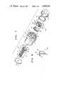
- FIG. 1is an exploded perspective drawing of a preferred embodiment of the electromagnetic flip-type visual indicator of the present invention
- FIG. 2is a side elevation in vertical section of the preferred embodiment of the electromagnetic flip-type visual indicator of FIG. 1;
- FIG. 3is a side elevation of the structural components of FIG. 2 rotated through an angle of 90°;
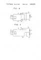
- FIGS. 4 and 5are schematic diagrams of electrical circuits, which can be used with the indicator of the present invention.
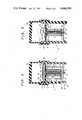
- FIG. 6ais a cross-sectional view of one embodiment of the flag and flag magnet assembly of the indicator of the present invention.
- FIG. 6bis a cross-sectional view of a second embodiment of the flag and flag magnet assembly of the indicator of the present invention.
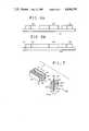
- FIG. 7is a simplified perspective drawing of another embodiment of the indicator of the present invention.
- FIG. 8is another embodiment of the flag assembly of the indicator of the present invention.
- the indicatorincludes a housing 10 which has an overall cylindrical shape and an exterior flange 12 near a first end of housing 10.
- the first end of housing 10is partially closed by an end portion 14 through which pass three rectangular holes 16, 18, 20.
- the first end of housing 10is provided with two grooves 50, 52 disposed along the circumference of housing 10 so that a line connecting the grooves 50, 52 intersects the axis of housing 10.
- the first end of housing 10 shown in FIG. 1is partially cut away in order that rectangular holes 16, 18, 20 may be seen.
- the exterior surface of the second end of housing 10may be threaded so that the indicator may be mounted on and secured to a panel such as by a threaded lock nut to draw the flange toward the panel.
- the housingmay be unthreaded and may be secured to a panel by an adhesive or other means as are known to those skilled in the art.
- the second end of housing 10has an opening 28 through which the two ends 22, 24 of wire 26 can pass.
- housing 10is preferably fabricated of a non-magnetic metal or of a plastic having the characteristics of strength, rigidity and impact strength among others as is appropriate for use as a support structure.
- Magnetic assembly 30is received and fixed within housing 10.
- Magnetic assembly 30includes a bobbin 32 (shown in FIGS. 2 and 3) fabricated of an insulating material, for example, plastic.
- a coil 27is formed by winding wire 26 a number of turns on bobbin 32 within a region bounded at opposite ends by flanges 34. The number of turns of coil 27 and the gauge of wire 26 will be determined by factors, such as the power of the source of the input, the desired resistance and other operational factors as are well known.
- Bobbin 32is mounted on core member 36 which is disposed within the central hollow of bobbin 32. A first end of core member 36 passes through and is fixed within a hole in bracket 40. A second end of core member 36 extends beyond flange 34 and is connected to core bar 38.
- bobbin 32is mounted on core member 36 between core bar 38 and bracket 40.
- Core bar 38is flat and rectangular in shape, is preferably a ferrous metal bar and is positioned on one flange 34 of bobbin 32.
- Bracket 40is U-shaped and is formed of a single piece of flat material, preferably ferrous metal, that is bent into a U-shape.
- Core bar 38 and bracket 40are preferably comprised of ferrous metal so that they can assume a magnetic polarity for reasons as will become apparent.
- Core bar 38 and bracket 40can be comprised of other materials which can assume a magnetic polarity.
- Magnetic assembly 30is mounted within housing 10 so that the end 68 of bracket 40 is mounted into rectangular hole 20 of end portion 14, end 70 of bracket 40 is mounted into rectangular hole 16 of end portion 14, and core bar 38 is mounted into rectangular hole 18 of end portion 14.
- Cap 42is inserted into the second end of housing 10 so that the two ends 22, 24 of wire 26 pass through opening 28 and so that magnetic assembly 30 is completely enclosed within housing 10.
- Cap 42has a hole 44 at its center through which the second end of core member 36 protrudes.
- End portion 14is completely covered by two semicircular segments 46, 48 which are attached to end portion 14 by a pressure sensitive adhesive so that the straight edges 120 of semicircular segments 46, 48 are parallel to a line which connects grooves 50, 52.
- the surfaces of semicircular segments 46, 48 not in contact with end portion 14are colored so that the color of the exposed surface of segment 46 contrasts highly with the color of the exposed surface of segment 48.
- the exposed surface of segment 46is orange and the exposed surface of segment 48 is black.
- Segments 46, 48are preferably fabricated of a non-magnetic material such as Mylar.
- pivot shaft 54The ends of pivot shaft 54 are rotatably mounted in grooves 50, 52 of housing 10.
- Semicircular flag 56is fixed to pivot shaft 54 along its straight edge and is preferably fabricated of a non-magnetic material such as Mylar.
- FIGS. 1 and 3semicircular flag 56 is shown in the "set” position in solid lines and in the "fault” position in broken lines.
- Flag 56is approximately the same size and shape as one of segments 46, 48 and is mounted so that flag 56 completely covers either segment 46 or segment 48.
- the color of surface 128 of flag 56 directed away from segment 46matches the color of segment 48.
- Permanent flag magnets 58, 60, 62are rectangular in shape, are fixed in a line to surface 128 of flag 56, and are magnetized so that the surfaces in contact with flag 56 of flag magnets 58, 60, 62 are magnetically polarized having alternating poles (south-north-south) while the other surfaces of the magnets have the three opposite poles (north-south-north) as shown in FIG. 6a.
- Flag magnets 58, 60, 62are attached to flag 56 adjacent the straight edge 122 of flag 56 in a line that is parallel to the straight edge 122 of flag 56.
- Flag magnets 58, 60, 62are colored so that the color of surface 126 of flag 56 to which flag magnets 58, 60, 62 are not attached contrasts highly with the exposed surface of flag magnets 58, 60, 62 and the other surface of flag 56.
- flag magnets 58, 60, 62 and surface 128 of flag 56 to which they are attachedare black and surface 126 of flag 56 is orange.
- segments 46, 48, flag 56 and flag magnets 58, 60, 62are painted with non-magnetic paint such as a rubber base paint. Alternatively, colored tape can be used.
- flag magnets 58, 60, 62are shown in FIGS.
- magnets 1, 2, and 6aas three discrete magnets, these magnets can alternatively be magnetized regions 158, 160, 162 of a single magnetic strip 100 which is appropriately magnetized as shown in FIG. 6b.
- Pivot shaft 54, flag 56, and flag magnets 58, 60, 62comprise flag assembly 150.
- Ring 64is mounted and secured onto the first end of housing 10 so that pivot shaft 54 is locked into grooves 50, 52.
- Ring 64is fabricated of a non-magnetic material such as plastic or rubber.
- Lens cap 66is mounted and secured onto ring 64 so that flag 56 is completely sealed within the cavity formed by housing 10 and lens cap 66.
- the shape of lens cap 66is such that flag 56 can rotate about the axis of pivot shaft 54 without interference by lens cap 66.
- Lens cap 66is preferably fabricated of a transparent non-magnetic material such as plastic or glass. In FIG. 1, lens cap 66 shown in FIG. 1 is partially cut away to show that lens cap 66 is a hollow cylinder closed off at one end.
- lens cap 66is shown as having a flat top, it may alternatively have a domed top. If the indicator is used as part of a large display panel comprised of a plurality of indicators, lens cap 66 can be omitted provided that the entire display panel is enclosed by a transparent cover so that air currents and other environmental factors will not interfere with the proper operation of the indicator.
- FIGS. 4 and 5illustrate possible circuit arrangements for connecting the indicator of the present invention to an electrical power supply.
- the high voltage output of power source 80is connected to a first terminal of single pole multiple throw switch 86 by wire 82, while the low voltage output of power source 80 is connected to a first terminal of single pole multiple throw switch 88 by wire 84.
- the second and third terminals of switches 86, 88are connected to ends 22, 24 of wire 26 of coil 27.
- Switches 86, 88are ganged together so that when switch 86 is in a first position whereby wire 82 is connected to wire 22, switch 88 is also in a first position whereby wire 84 is connected to wire 24; while when switch 86 is in a second position, wire 82 is connected to wire 24, and switch 88 is also in a second position whereby wire 84 is connected to wire 22.
- switches 86, 88are preferably momentary contact switches which connect power source 80 to coil 27 momentarily.
- FIG. 5shows an alternative circuit arrangement which uses only one single pole multiple throw momentary contact switch 90.
- Coil 27, however,is a center tapped coil and therefore has three wires 84, 92, 94 connected to it.
- switch 90when switch 90 is in a first position, coil 27 generates a magnetic pulse in a first direction while when switch 90 is in a second position, coil 27 generates a magnetic pulse in an anti-parallel second direction.
- Other circuit arrangementswill be apparent to those skilled in the art.
- flag 56In operation, when flag 56 is in either the "set” or “fault” position, the magnetic attraction between flag magnets 58, 60, 62 on the one hand and the ends 68, 70 of bracket 40 and core bar 38 on the other hand latch flag 56 in either of these two positions.
- flag magnet 58is magnetically attracted to end 68 of bracket 40
- flag magnet 60is magnetically attracted to core bar 38
- flag magnet 62is magnetically attracted to end 70 of bracket 40. Ends 68, 70 of bracket 40 and core bar 38 will frequently remain magnetized from a previous operation of the indicator and will thus aid in magnetically latching flag 56.
- ends 68, 70 of bracket 40 and core bar 38will change depending upon the magnetization of coil 27, for illustrative purposes, ends 68, 70 are shown as having north (N) poles while core bar 38 is shown as having a south (S) pole. Since bracket 40 and ends 68, 70 are magnetically connected to the first end of the electromagnet while core bar 38 is magnetically connected to the second end of the electromagnet, ends 68, 70 will always have an opposite magnetic pole from that of core bar 38.
- Flag 56After flag 56 has passed the midpoint between its "set” and “fault” positions, the rotation of flag 56 is aided by the attractive forces between flag magnet 62 (north) and end 70 (south), between flag magnet 60 (south) and core bar 38 (north); and between flag magnet 58 (north) and end 68 (south).
- Coil 27must be connected to power source 80 by switches 86, 88 (or switch 90) for a long enough time so that flag 56 flips from the "set” to the "fault” position.
- flag 56has rotated into the "fault” position, the magnetic attractive forces between flag magnets 58, 68, 62 on the one hand, and ends 60, 70 and core bar 38 on the other hand cause flag 56 to be latched in the "fault” position after coil 27 is disconnected from power source 80.
- ends 68, 70 and core bar 38maintain their magnetic polarities until the indicator is operated again by connecting coil 27 to the opposite terminal of power source 80, as discussed below. If ends 68, 70 and core bar 38 should lose their magnetic polarity, flag 56 will continue to be latched in position due to the magnetic attraction between the flag magnets on the one hand and the ferrous metal comprising ends 68, 70 and core bar 38 on the other hand.
- switches 86, 88(or switch 90) connects power source 80 to coil 27 so that the end of coil 27 near core bar 38 has a magnetic south pole thereby magnetizing core bar 38 with a south polarity and repelling the south pole of flag magnet 60. Additionally, coil 27 causes bracket 40 and ends 68, 70 to assume a north polarity thereby repelling flag magnets 58, 62 which also have a north polarity.
- FIG. 7is a simplified drawing of another embodiment of the indicator of the present invention. Although only magnetic assembly 30 and flag assembly 150 are shown in FIG. 7, the remainder of the indicator is the same as in the embodiment shown in FIGS. 1, 2 and 3.
- semicircular flag 56is shown in the "set” position in solid lines and in the "fault” position in broken lines. In this embodiment, only two flag magnets are used.
- Central flag magnet 102is attached to flag 56 adjacent the straight edge of flag 56.
- Outer flag magnet 104is attached to flag 56 along the curved edge of flag 56 as shown in FIG. 7.
- Flag magnets 102, 104are magnetized in a fashion similar to the way flag magnets 58, 60, 62 are magnetized in the embodiment shown in FIGS. 1, 2, and 3, so that the surfaces in contact with flag 56 have one pole while the other surfaces of the magnets have opposite poles.
- the embodiment shown in FIG. 7also differs from that shown in FIG. 1 in that the axis of rotation of pivot shaft 54 shown in FIG. 7 is rotated 90° from that shown in FIG. 1.
- arm 110is fixedly connected to pivot shaft 54 to act as a counter-weight to flag 56 and the flag magnets attached thereto.
- arm 110also rotates.
- End portion 14is provided with a hole (not shown) with an appropriate size and shape so that the rotation of arm 110 is not impeded.
- poles of all the flag magnetscan be reversed so that all north (N) poles are south (S) poles and all south (S) poles are north (N) poles.
- flag 56can have other shapes or can alternatively be replaced by more than one flag each of which being operated by the same magnetic assembly 30 or by separate magnetic assemblies so that when the coil(s) of the magnetic assembly (assemblies) is (are) activated, the flags flip from one position to the other position. If more than one magnetic assembly is used, the magnetic assemblies can also be selectively activated to cause only certain flags to change position, thereby resulting in a distinctive pattern associated with a particular condition of a monitored device.
Landscapes
- Physics & Mathematics (AREA)
- General Physics & Mathematics (AREA)
- Electromagnetism (AREA)
- Engineering & Computer Science (AREA)
- Theoretical Computer Science (AREA)
- Devices For Indicating Variable Information By Combining Individual Elements (AREA)
Abstract
Description
Claims (26)
Priority Applications (1)
| Application Number | Priority Date | Filing Date | Title |
|---|---|---|---|
| US06/802,647US4694599A (en) | 1985-11-27 | 1985-11-27 | Electromagnetic flip-type visual indicator |
Applications Claiming Priority (1)
| Application Number | Priority Date | Filing Date | Title |
|---|---|---|---|
| US06/802,647US4694599A (en) | 1985-11-27 | 1985-11-27 | Electromagnetic flip-type visual indicator |
Publications (1)
| Publication Number | Publication Date |
|---|---|
| US4694599Atrue US4694599A (en) | 1987-09-22 |
Family
ID=25184314
Family Applications (1)
| Application Number | Title | Priority Date | Filing Date |
|---|---|---|---|
| US06/802,647Expired - LifetimeUS4694599A (en) | 1985-11-27 | 1985-11-27 | Electromagnetic flip-type visual indicator |
Country Status (1)
| Country | Link |
|---|---|
| US (1) | US4694599A (en) |
Cited By (171)
| Publication number | Priority date | Publication date | Assignee | Title |
|---|---|---|---|---|
| US5111193A (en)* | 1990-06-06 | 1992-05-05 | American On-Premise Advertising Company | Electronic display element for electronic display device |
| US5148156A (en)* | 1990-06-06 | 1992-09-15 | American Electronic Sign Company | Electronic display device having a plurality of pixel elements |
| FR2719676A1 (en)* | 1994-05-06 | 1995-11-10 | Bosch Gmbh Robert | Vehicle equipped with a regulation system. |
| US5497096A (en)* | 1993-07-02 | 1996-03-05 | Cooper Industries, Inc. | Faulted circuit indictor with three-dimensional display device |
| US5526016A (en)* | 1991-06-28 | 1996-06-11 | Citizen Watch Co., Ltd. | Multicolor display apparatus |
| US5748095A (en)* | 1996-07-15 | 1998-05-05 | Dipl.-Ing H. Horstmann Gmbh | Mini faulted circuit indicator unit |
| US6677922B1 (en) | 1995-12-04 | 2004-01-13 | 3M Innovative Properties Company | Display element having retroreflective surface |
| US20050161989A1 (en)* | 2004-01-26 | 2005-07-28 | Good Decision Products, Llc | Apparatus and system for facilitating child discipline |
| US20080100436A1 (en)* | 2006-10-26 | 2008-05-01 | John Fredrick Banting | Electrical power system control communications network |
| US20080177481A1 (en)* | 2007-01-23 | 2008-07-24 | Bionorica Ag | Method for classifying scientific materials such as silicate materials, polymer materials and/or nanomaterials |
| US20090115426A1 (en)* | 2007-11-02 | 2009-05-07 | Cooper Technologies Company | Faulted circuit indicator apparatus with transmission line state display and method of use thereof |
| US20090231764A1 (en)* | 2008-03-14 | 2009-09-17 | Cooper Technologies Company | Capacitor Bank Monitor and Method of use Thereof |
| US20100084920A1 (en)* | 2007-11-02 | 2010-04-08 | Cooper Technologies Company | Power Line Energy Harvesting Power Supply |
| US20100085036A1 (en)* | 2007-11-02 | 2010-04-08 | Cooper Technologies Company | Overhead Communicating Device |
| US20110005312A1 (en)* | 2009-07-13 | 2011-01-13 | Henry Hopper | Process Tanks in Combination with a Float Magnetostrictive Level Detector |
| US7930141B2 (en) | 2007-11-02 | 2011-04-19 | Cooper Technologies Company | Communicating faulted circuit indicator apparatus and method of use thereof |
| US8760254B2 (en) | 2010-08-10 | 2014-06-24 | Cooper Technologies Company | Apparatus and method for mounting an overhead monitoring device |
| US9379556B2 (en) | 2013-03-14 | 2016-06-28 | Cooper Technologies Company | Systems and methods for energy harvesting and current and voltage measurements |
| US9544006B2 (en) | 2014-11-20 | 2017-01-10 | At&T Intellectual Property I, L.P. | Transmission device with mode division multiplexing and methods for use therewith |
| US9596001B2 (en) | 2014-10-21 | 2017-03-14 | At&T Intellectual Property I, L.P. | Apparatus for providing communication services and methods thereof |
| US9608692B2 (en) | 2015-06-11 | 2017-03-28 | At&T Intellectual Property I, L.P. | Repeater and methods for use therewith |
| US9608740B2 (en) | 2015-07-15 | 2017-03-28 | At&T Intellectual Property I, L.P. | Method and apparatus for launching a wave mode that mitigates interference |
| US9615269B2 (en) | 2014-10-02 | 2017-04-04 | At&T Intellectual Property I, L.P. | Method and apparatus that provides fault tolerance in a communication network |
| US9628116B2 (en) | 2015-07-14 | 2017-04-18 | At&T Intellectual Property I, L.P. | Apparatus and methods for transmitting wireless signals |
| US9627768B2 (en) | 2014-10-21 | 2017-04-18 | At&T Intellectual Property I, L.P. | Guided-wave transmission device with non-fundamental mode propagation and methods for use therewith |
| US9640850B2 (en) | 2015-06-25 | 2017-05-02 | At&T Intellectual Property I, L.P. | Methods and apparatus for inducing a non-fundamental wave mode on a transmission medium |
| US9653770B2 (en) | 2014-10-21 | 2017-05-16 | At&T Intellectual Property I, L.P. | Guided wave coupler, coupling module and methods for use therewith |
| US9654173B2 (en) | 2014-11-20 | 2017-05-16 | At&T Intellectual Property I, L.P. | Apparatus for powering a communication device and methods thereof |
| US9661505B2 (en) | 2013-11-06 | 2017-05-23 | At&T Intellectual Property I, L.P. | Surface-wave communications and methods thereof |
| US9667317B2 (en) | 2015-06-15 | 2017-05-30 | At&T Intellectual Property I, L.P. | Method and apparatus for providing security using network traffic adjustments |
| US9685992B2 (en) | 2014-10-03 | 2017-06-20 | At&T Intellectual Property I, L.P. | Circuit panel network and methods thereof |
| US9692101B2 (en) | 2014-08-26 | 2017-06-27 | At&T Intellectual Property I, L.P. | Guided wave couplers for coupling electromagnetic waves between a waveguide surface and a surface of a wire |
| US9699785B2 (en) | 2012-12-05 | 2017-07-04 | At&T Intellectual Property I, L.P. | Backhaul link for distributed antenna system |
| US9705561B2 (en) | 2015-04-24 | 2017-07-11 | At&T Intellectual Property I, L.P. | Directional coupling device and methods for use therewith |
| US9705610B2 (en) | 2014-10-21 | 2017-07-11 | At&T Intellectual Property I, L.P. | Transmission device with impairment compensation and methods for use therewith |
| US9712350B2 (en) | 2014-11-20 | 2017-07-18 | At&T Intellectual Property I, L.P. | Transmission device with channel equalization and control and methods for use therewith |
| US9722318B2 (en) | 2015-07-14 | 2017-08-01 | At&T Intellectual Property I, L.P. | Method and apparatus for coupling an antenna to a device |
| US9729197B2 (en) | 2015-10-01 | 2017-08-08 | At&T Intellectual Property I, L.P. | Method and apparatus for communicating network management traffic over a network |
| US9735833B2 (en) | 2015-07-31 | 2017-08-15 | At&T Intellectual Property I, L.P. | Method and apparatus for communications management in a neighborhood network |
| US9742462B2 (en) | 2014-12-04 | 2017-08-22 | At&T Intellectual Property I, L.P. | Transmission medium and communication interfaces and methods for use therewith |
| US9748626B2 (en) | 2015-05-14 | 2017-08-29 | At&T Intellectual Property I, L.P. | Plurality of cables having different cross-sectional shapes which are bundled together to form a transmission medium |
| US9749053B2 (en) | 2015-07-23 | 2017-08-29 | At&T Intellectual Property I, L.P. | Node device, repeater and methods for use therewith |
| US9749013B2 (en) | 2015-03-17 | 2017-08-29 | At&T Intellectual Property I, L.P. | Method and apparatus for reducing attenuation of electromagnetic waves guided by a transmission medium |
| US9762289B2 (en) | 2014-10-14 | 2017-09-12 | At&T Intellectual Property I, L.P. | Method and apparatus for transmitting or receiving signals in a transportation system |
| US9769020B2 (en) | 2014-10-21 | 2017-09-19 | At&T Intellectual Property I, L.P. | Method and apparatus for responding to events affecting communications in a communication network |
| US9769128B2 (en) | 2015-09-28 | 2017-09-19 | At&T Intellectual Property I, L.P. | Method and apparatus for encryption of communications over a network |
| US9768833B2 (en) | 2014-09-15 | 2017-09-19 | At&T Intellectual Property I, L.P. | Method and apparatus for sensing a condition in a transmission medium of electromagnetic waves |
| US9780834B2 (en) | 2014-10-21 | 2017-10-03 | At&T Intellectual Property I, L.P. | Method and apparatus for transmitting electromagnetic waves |
| US9787412B2 (en) | 2015-06-25 | 2017-10-10 | At&T Intellectual Property I, L.P. | Methods and apparatus for inducing a fundamental wave mode on a transmission medium |
| US9793954B2 (en) | 2015-04-28 | 2017-10-17 | At&T Intellectual Property I, L.P. | Magnetic coupling device and methods for use therewith |
| US9793955B2 (en) | 2015-04-24 | 2017-10-17 | At&T Intellectual Property I, Lp | Passive electrical coupling device and methods for use therewith |
| US9793951B2 (en) | 2015-07-15 | 2017-10-17 | At&T Intellectual Property I, L.P. | Method and apparatus for launching a wave mode that mitigates interference |
| US9794003B2 (en) | 2013-12-10 | 2017-10-17 | At&T Intellectual Property I, L.P. | Quasi-optical coupler |
| US9800327B2 (en) | 2014-11-20 | 2017-10-24 | At&T Intellectual Property I, L.P. | Apparatus for controlling operations of a communication device and methods thereof |
| US9820146B2 (en) | 2015-06-12 | 2017-11-14 | At&T Intellectual Property I, L.P. | Method and apparatus for authentication and identity management of communicating devices |
| US9827504B2 (en) | 2012-05-19 | 2017-11-28 | Kenneth E. Olson | Vibratory device for bobble toys |
| US9838896B1 (en) | 2016-12-09 | 2017-12-05 | At&T Intellectual Property I, L.P. | Method and apparatus for assessing network coverage |
| US9836957B2 (en) | 2015-07-14 | 2017-12-05 | At&T Intellectual Property I, L.P. | Method and apparatus for communicating with premises equipment |
| US9838078B2 (en) | 2015-07-31 | 2017-12-05 | At&T Intellectual Property I, L.P. | Method and apparatus for exchanging communication signals |
| US9847566B2 (en) | 2015-07-14 | 2017-12-19 | At&T Intellectual Property I, L.P. | Method and apparatus for adjusting a field of a signal to mitigate interference |
| US9847850B2 (en) | 2014-10-14 | 2017-12-19 | At&T Intellectual Property I, L.P. | Method and apparatus for adjusting a mode of communication in a communication network |
| US9853342B2 (en) | 2015-07-14 | 2017-12-26 | At&T Intellectual Property I, L.P. | Dielectric transmission medium connector and methods for use therewith |
| US9860075B1 (en) | 2016-08-26 | 2018-01-02 | At&T Intellectual Property I, L.P. | Method and communication node for broadband distribution |
| US9865911B2 (en) | 2015-06-25 | 2018-01-09 | At&T Intellectual Property I, L.P. | Waveguide system for slot radiating first electromagnetic waves that are combined into a non-fundamental wave mode second electromagnetic wave on a transmission medium |
| US9866309B2 (en) | 2015-06-03 | 2018-01-09 | At&T Intellectual Property I, Lp | Host node device and methods for use therewith |
| US9866276B2 (en) | 2014-10-10 | 2018-01-09 | At&T Intellectual Property I, L.P. | Method and apparatus for arranging communication sessions in a communication system |
| US9871283B2 (en) | 2015-07-23 | 2018-01-16 | At&T Intellectual Property I, Lp | Transmission medium having a dielectric core comprised of plural members connected by a ball and socket configuration |
| US9871558B2 (en) | 2014-10-21 | 2018-01-16 | At&T Intellectual Property I, L.P. | Guided-wave transmission device and methods for use therewith |
| US9871282B2 (en) | 2015-05-14 | 2018-01-16 | At&T Intellectual Property I, L.P. | At least one transmission medium having a dielectric surface that is covered at least in part by a second dielectric |
| US9876570B2 (en) | 2015-02-20 | 2018-01-23 | At&T Intellectual Property I, Lp | Guided-wave transmission device with non-fundamental mode propagation and methods for use therewith |
| US9876264B2 (en) | 2015-10-02 | 2018-01-23 | At&T Intellectual Property I, Lp | Communication system, guided wave switch and methods for use therewith |
| US9876605B1 (en) | 2016-10-21 | 2018-01-23 | At&T Intellectual Property I, L.P. | Launcher and coupling system to support desired guided wave mode |
| US9882277B2 (en) | 2015-10-02 | 2018-01-30 | At&T Intellectual Property I, Lp | Communication device and antenna assembly with actuated gimbal mount |
| US9882257B2 (en) | 2015-07-14 | 2018-01-30 | At&T Intellectual Property I, L.P. | Method and apparatus for launching a wave mode that mitigates interference |
| US9887447B2 (en) | 2015-05-14 | 2018-02-06 | At&T Intellectual Property I, L.P. | Transmission medium having multiple cores and methods for use therewith |
| US9893795B1 (en) | 2016-12-07 | 2018-02-13 | At&T Intellectual Property I, Lp | Method and repeater for broadband distribution |
| US9904535B2 (en) | 2015-09-14 | 2018-02-27 | At&T Intellectual Property I, L.P. | Method and apparatus for distributing software |
| US9906269B2 (en) | 2014-09-17 | 2018-02-27 | At&T Intellectual Property I, L.P. | Monitoring and mitigating conditions in a communication network |
| US9912419B1 (en) | 2016-08-24 | 2018-03-06 | At&T Intellectual Property I, L.P. | Method and apparatus for managing a fault in a distributed antenna system |
| US9912027B2 (en) | 2015-07-23 | 2018-03-06 | At&T Intellectual Property I, L.P. | Method and apparatus for exchanging communication signals |
| US9912382B2 (en) | 2015-06-03 | 2018-03-06 | At&T Intellectual Property I, Lp | Network termination and methods for use therewith |
| US9913139B2 (en) | 2015-06-09 | 2018-03-06 | At&T Intellectual Property I, L.P. | Signal fingerprinting for authentication of communicating devices |
| US9911020B1 (en) | 2016-12-08 | 2018-03-06 | At&T Intellectual Property I, L.P. | Method and apparatus for tracking via a radio frequency identification device |
| US9917341B2 (en) | 2015-05-27 | 2018-03-13 | At&T Intellectual Property I, L.P. | Apparatus and method for launching electromagnetic waves and for modifying radial dimensions of the propagating electromagnetic waves |
| US9930668B2 (en) | 2013-05-31 | 2018-03-27 | At&T Intellectual Property I, L.P. | Remote distributed antenna system |
| US9927517B1 (en) | 2016-12-06 | 2018-03-27 | At&T Intellectual Property I, L.P. | Apparatus and methods for sensing rainfall |
| US9948354B2 (en) | 2015-04-28 | 2018-04-17 | At&T Intellectual Property I, L.P. | Magnetic coupling device with reflective plate and methods for use therewith |
| US9948333B2 (en) | 2015-07-23 | 2018-04-17 | At&T Intellectual Property I, L.P. | Method and apparatus for wireless communications to mitigate interference |
| US9954287B2 (en) | 2014-11-20 | 2018-04-24 | At&T Intellectual Property I, L.P. | Apparatus for converting wireless signals and electromagnetic waves and methods thereof |
| US9967173B2 (en) | 2015-07-31 | 2018-05-08 | At&T Intellectual Property I, L.P. | Method and apparatus for authentication and identity management of communicating devices |
| US9973940B1 (en) | 2017-02-27 | 2018-05-15 | At&T Intellectual Property I, L.P. | Apparatus and methods for dynamic impedance matching of a guided wave launcher |
| US9991580B2 (en) | 2016-10-21 | 2018-06-05 | At&T Intellectual Property I, L.P. | Launcher and coupling system for guided wave mode cancellation |
| US9998870B1 (en) | 2016-12-08 | 2018-06-12 | At&T Intellectual Property I, L.P. | Method and apparatus for proximity sensing |
| US9999038B2 (en) | 2013-05-31 | 2018-06-12 | At&T Intellectual Property I, L.P. | Remote distributed antenna system |
| US9997819B2 (en) | 2015-06-09 | 2018-06-12 | At&T Intellectual Property I, L.P. | Transmission medium and method for facilitating propagation of electromagnetic waves via a core |
| US10009067B2 (en) | 2014-12-04 | 2018-06-26 | At&T Intellectual Property I, L.P. | Method and apparatus for configuring a communication interface |
| US10009063B2 (en) | 2015-09-16 | 2018-06-26 | At&T Intellectual Property I, L.P. | Method and apparatus for use with a radio distributed antenna system having an out-of-band reference signal |
| US10009901B2 (en) | 2015-09-16 | 2018-06-26 | At&T Intellectual Property I, L.P. | Method, apparatus, and computer-readable storage medium for managing utilization of wireless resources between base stations |
| US10009065B2 (en) | 2012-12-05 | 2018-06-26 | At&T Intellectual Property I, L.P. | Backhaul link for distributed antenna system |
| US10020844B2 (en) | 2016-12-06 | 2018-07-10 | T&T Intellectual Property I, L.P. | Method and apparatus for broadcast communication via guided waves |
| US10020587B2 (en) | 2015-07-31 | 2018-07-10 | At&T Intellectual Property I, L.P. | Radial antenna and methods for use therewith |
| US10027397B2 (en) | 2016-12-07 | 2018-07-17 | At&T Intellectual Property I, L.P. | Distributed antenna system and methods for use therewith |
| US10033107B2 (en) | 2015-07-14 | 2018-07-24 | At&T Intellectual Property I, L.P. | Method and apparatus for coupling an antenna to a device |
| US10033108B2 (en) | 2015-07-14 | 2018-07-24 | At&T Intellectual Property I, L.P. | Apparatus and methods for generating an electromagnetic wave having a wave mode that mitigates interference |
| US10044409B2 (en) | 2015-07-14 | 2018-08-07 | At&T Intellectual Property I, L.P. | Transmission medium and methods for use therewith |
| US10069535B2 (en) | 2016-12-08 | 2018-09-04 | At&T Intellectual Property I, L.P. | Apparatus and methods for launching electromagnetic waves having a certain electric field structure |
| US10079661B2 (en) | 2015-09-16 | 2018-09-18 | At&T Intellectual Property I, L.P. | Method and apparatus for use with a radio distributed antenna system having a clock reference |
| US10090606B2 (en) | 2015-07-15 | 2018-10-02 | At&T Intellectual Property I, L.P. | Antenna system with dielectric array and methods for use therewith |
| US10090594B2 (en) | 2016-11-23 | 2018-10-02 | At&T Intellectual Property I, L.P. | Antenna system having structural configurations for assembly |
| US10103422B2 (en) | 2016-12-08 | 2018-10-16 | At&T Intellectual Property I, L.P. | Method and apparatus for mounting network devices |
| US10103801B2 (en) | 2015-06-03 | 2018-10-16 | At&T Intellectual Property I, L.P. | Host node device and methods for use therewith |
| US10135146B2 (en) | 2016-10-18 | 2018-11-20 | At&T Intellectual Property I, L.P. | Apparatus and methods for launching guided waves via circuits |
| US10136434B2 (en) | 2015-09-16 | 2018-11-20 | At&T Intellectual Property I, L.P. | Method and apparatus for use with a radio distributed antenna system having an ultra-wideband control channel |
| US10135145B2 (en) | 2016-12-06 | 2018-11-20 | At&T Intellectual Property I, L.P. | Apparatus and methods for generating an electromagnetic wave along a transmission medium |
| US10135147B2 (en) | 2016-10-18 | 2018-11-20 | At&T Intellectual Property I, L.P. | Apparatus and methods for launching guided waves via an antenna |
| US10142086B2 (en) | 2015-06-11 | 2018-11-27 | At&T Intellectual Property I, L.P. | Repeater and methods for use therewith |
| US10139820B2 (en) | 2016-12-07 | 2018-11-27 | At&T Intellectual Property I, L.P. | Method and apparatus for deploying equipment of a communication system |
| US10148016B2 (en) | 2015-07-14 | 2018-12-04 | At&T Intellectual Property I, L.P. | Apparatus and methods for communicating utilizing an antenna array |
| US10144036B2 (en) | 2015-01-30 | 2018-12-04 | At&T Intellectual Property I, L.P. | Method and apparatus for mitigating interference affecting a propagation of electromagnetic waves guided by a transmission medium |
| US10170840B2 (en) | 2015-07-14 | 2019-01-01 | At&T Intellectual Property I, L.P. | Apparatus and methods for sending or receiving electromagnetic signals |
| US10168695B2 (en) | 2016-12-07 | 2019-01-01 | At&T Intellectual Property I, L.P. | Method and apparatus for controlling an unmanned aircraft |
| US10178445B2 (en) | 2016-11-23 | 2019-01-08 | At&T Intellectual Property I, L.P. | Methods, devices, and systems for load balancing between a plurality of waveguides |
| US10205655B2 (en) | 2015-07-14 | 2019-02-12 | At&T Intellectual Property I, L.P. | Apparatus and methods for communicating utilizing an antenna array and multiple communication paths |
| US10224634B2 (en) | 2016-11-03 | 2019-03-05 | At&T Intellectual Property I, L.P. | Methods and apparatus for adjusting an operational characteristic of an antenna |
| US10225025B2 (en) | 2016-11-03 | 2019-03-05 | At&T Intellectual Property I, L.P. | Method and apparatus for detecting a fault in a communication system |
| US10243270B2 (en) | 2016-12-07 | 2019-03-26 | At&T Intellectual Property I, L.P. | Beam adaptive multi-feed dielectric antenna system and methods for use therewith |
| US10243784B2 (en) | 2014-11-20 | 2019-03-26 | At&T Intellectual Property I, L.P. | System for generating topology information and methods thereof |
| US10264586B2 (en) | 2016-12-09 | 2019-04-16 | At&T Mobility Ii Llc | Cloud-based packet controller and methods for use therewith |
| US10291311B2 (en) | 2016-09-09 | 2019-05-14 | At&T Intellectual Property I, L.P. | Method and apparatus for mitigating a fault in a distributed antenna system |
| US10291334B2 (en) | 2016-11-03 | 2019-05-14 | At&T Intellectual Property I, L.P. | System for detecting a fault in a communication system |
| US10298293B2 (en) | 2017-03-13 | 2019-05-21 | At&T Intellectual Property I, L.P. | Apparatus of communication utilizing wireless network devices |
| US10305190B2 (en) | 2016-12-01 | 2019-05-28 | At&T Intellectual Property I, L.P. | Reflecting dielectric antenna system and methods for use therewith |
| US10312567B2 (en) | 2016-10-26 | 2019-06-04 | At&T Intellectual Property I, L.P. | Launcher with planar strip antenna and methods for use therewith |
| US10320586B2 (en) | 2015-07-14 | 2019-06-11 | At&T Intellectual Property I, L.P. | Apparatus and methods for generating non-interfering electromagnetic waves on an insulated transmission medium |
| US10326689B2 (en) | 2016-12-08 | 2019-06-18 | At&T Intellectual Property I, L.P. | Method and system for providing alternative communication paths |
| US10326494B2 (en) | 2016-12-06 | 2019-06-18 | At&T Intellectual Property I, L.P. | Apparatus for measurement de-embedding and methods for use therewith |
| US10340603B2 (en) | 2016-11-23 | 2019-07-02 | At&T Intellectual Property I, L.P. | Antenna system having shielded structural configurations for assembly |
| US10340573B2 (en) | 2016-10-26 | 2019-07-02 | At&T Intellectual Property I, L.P. | Launcher with cylindrical coupling device and methods for use therewith |
| US10340601B2 (en) | 2016-11-23 | 2019-07-02 | At&T Intellectual Property I, L.P. | Multi-antenna system and methods for use therewith |
| US10340983B2 (en) | 2016-12-09 | 2019-07-02 | At&T Intellectual Property I, L.P. | Method and apparatus for surveying remote sites via guided wave communications |
| US10340600B2 (en) | 2016-10-18 | 2019-07-02 | At&T Intellectual Property I, L.P. | Apparatus and methods for launching guided waves via plural waveguide systems |
| US10341142B2 (en) | 2015-07-14 | 2019-07-02 | At&T Intellectual Property I, L.P. | Apparatus and methods for generating non-interfering electromagnetic waves on an uninsulated conductor |
| US10355367B2 (en) | 2015-10-16 | 2019-07-16 | At&T Intellectual Property I, L.P. | Antenna structure for exchanging wireless signals |
| US10361489B2 (en) | 2016-12-01 | 2019-07-23 | At&T Intellectual Property I, L.P. | Dielectric dish antenna system and methods for use therewith |
| US10359749B2 (en) | 2016-12-07 | 2019-07-23 | At&T Intellectual Property I, L.P. | Method and apparatus for utilities management via guided wave communication |
| US10374316B2 (en) | 2016-10-21 | 2019-08-06 | At&T Intellectual Property I, L.P. | System and dielectric antenna with non-uniform dielectric |
| US10382976B2 (en) | 2016-12-06 | 2019-08-13 | At&T Intellectual Property I, L.P. | Method and apparatus for managing wireless communications based on communication paths and network device positions |
| US10389029B2 (en) | 2016-12-07 | 2019-08-20 | At&T Intellectual Property I, L.P. | Multi-feed dielectric antenna system with core selection and methods for use therewith |
| US10389037B2 (en) | 2016-12-08 | 2019-08-20 | At&T Intellectual Property I, L.P. | Apparatus and methods for selecting sections of an antenna array and use therewith |
| US10411356B2 (en) | 2016-12-08 | 2019-09-10 | At&T Intellectual Property I, L.P. | Apparatus and methods for selectively targeting communication devices with an antenna array |
| US10439675B2 (en) | 2016-12-06 | 2019-10-08 | At&T Intellectual Property I, L.P. | Method and apparatus for repeating guided wave communication signals |
| US10446936B2 (en) | 2016-12-07 | 2019-10-15 | At&T Intellectual Property I, L.P. | Multi-feed dielectric antenna system and methods for use therewith |
| US10498044B2 (en) | 2016-11-03 | 2019-12-03 | At&T Intellectual Property I, L.P. | Apparatus for configuring a surface of an antenna |
| US10530505B2 (en) | 2016-12-08 | 2020-01-07 | At&T Intellectual Property I, L.P. | Apparatus and methods for launching electromagnetic waves along a transmission medium |
| US10535928B2 (en) | 2016-11-23 | 2020-01-14 | At&T Intellectual Property I, L.P. | Antenna system and methods for use therewith |
| US10547348B2 (en) | 2016-12-07 | 2020-01-28 | At&T Intellectual Property I, L.P. | Method and apparatus for switching transmission mediums in a communication system |
| US10601494B2 (en) | 2016-12-08 | 2020-03-24 | At&T Intellectual Property I, L.P. | Dual-band communication device and method for use therewith |
| US10637149B2 (en) | 2016-12-06 | 2020-04-28 | At&T Intellectual Property I, L.P. | Injection molded dielectric antenna and methods for use therewith |
| US10650940B2 (en) | 2015-05-15 | 2020-05-12 | At&T Intellectual Property I, L.P. | Transmission medium having a conductive material and methods for use therewith |
| US10665942B2 (en) | 2015-10-16 | 2020-05-26 | At&T Intellectual Property I, L.P. | Method and apparatus for adjusting wireless communications |
| US10694379B2 (en) | 2016-12-06 | 2020-06-23 | At&T Intellectual Property I, L.P. | Waveguide system with device-based authentication and methods for use therewith |
| US10727599B2 (en) | 2016-12-06 | 2020-07-28 | At&T Intellectual Property I, L.P. | Launcher with slot antenna and methods for use therewith |
| US10755542B2 (en) | 2016-12-06 | 2020-08-25 | At&T Intellectual Property I, L.P. | Method and apparatus for surveillance via guided wave communication |
| US10777873B2 (en) | 2016-12-08 | 2020-09-15 | At&T Intellectual Property I, L.P. | Method and apparatus for mounting network devices |
| US10784670B2 (en) | 2015-07-23 | 2020-09-22 | At&T Intellectual Property I, L.P. | Antenna support for aligning an antenna |
| US10797781B2 (en) | 2015-06-03 | 2020-10-06 | At&T Intellectual Property I, L.P. | Client node device and methods for use therewith |
| US10811767B2 (en) | 2016-10-21 | 2020-10-20 | At&T Intellectual Property I, L.P. | System and dielectric antenna with convex dielectric radome |
| US10819035B2 (en) | 2016-12-06 | 2020-10-27 | At&T Intellectual Property I, L.P. | Launcher with helical antenna and methods for use therewith |
| US10916969B2 (en) | 2016-12-08 | 2021-02-09 | At&T Intellectual Property I, L.P. | Method and apparatus for providing power using an inductive coupling |
| US10938108B2 (en) | 2016-12-08 | 2021-03-02 | At&T Intellectual Property I, L.P. | Frequency selective multi-feed dielectric antenna system and methods for use therewith |
| US11032819B2 (en) | 2016-09-15 | 2021-06-08 | At&T Intellectual Property I, L.P. | Method and apparatus for use with a radio distributed antenna system having a control channel reference signal |
Citations (6)
| Publication number | Priority date | Publication date | Assignee | Title |
|---|---|---|---|---|
| US3295238A (en)* | 1963-11-01 | 1967-01-03 | Ferranti Packard Ltd | Sign element |
| US3422426A (en)* | 1967-04-10 | 1969-01-14 | Switchcraft | Electromagnetic signal device having movable permanent magnet |
| US3624941A (en)* | 1969-12-29 | 1971-12-07 | Ferranti Packard Ltd | Reversible sign element |
| DE2306067A1 (en)* | 1972-02-11 | 1973-09-06 | Fok Gyem Finommech Elekt | DEVICE FOR THE QUICK DISPLAY OF VISUAL INFORMATION DEVELOPED BY MAGNETIC DISPLAY ELEMENTS IN THE MOSAIC SYSTEM |
| US4259801A (en)* | 1977-04-22 | 1981-04-07 | Kokusai Display Kogyo Co., Ltd. | Display device |
| DE3335922A1 (en)* | 1983-10-03 | 1985-04-18 | Horst Dipl.-Ing. Hendel (FH), 8031 Eichenau | Display panel for the visual representation of information |
- 1985
- 1985-11-27USUS06/802,647patent/US4694599A/ennot_activeExpired - Lifetime
Patent Citations (6)
| Publication number | Priority date | Publication date | Assignee | Title |
|---|---|---|---|---|
| US3295238A (en)* | 1963-11-01 | 1967-01-03 | Ferranti Packard Ltd | Sign element |
| US3422426A (en)* | 1967-04-10 | 1969-01-14 | Switchcraft | Electromagnetic signal device having movable permanent magnet |
| US3624941A (en)* | 1969-12-29 | 1971-12-07 | Ferranti Packard Ltd | Reversible sign element |
| DE2306067A1 (en)* | 1972-02-11 | 1973-09-06 | Fok Gyem Finommech Elekt | DEVICE FOR THE QUICK DISPLAY OF VISUAL INFORMATION DEVELOPED BY MAGNETIC DISPLAY ELEMENTS IN THE MOSAIC SYSTEM |
| US4259801A (en)* | 1977-04-22 | 1981-04-07 | Kokusai Display Kogyo Co., Ltd. | Display device |
| DE3335922A1 (en)* | 1983-10-03 | 1985-04-18 | Horst Dipl.-Ing. Hendel (FH), 8031 Eichenau | Display panel for the visual representation of information |
Cited By (218)
| Publication number | Priority date | Publication date | Assignee | Title |
|---|---|---|---|---|
| US5148156A (en)* | 1990-06-06 | 1992-09-15 | American Electronic Sign Company | Electronic display device having a plurality of pixel elements |
| US5111193A (en)* | 1990-06-06 | 1992-05-05 | American On-Premise Advertising Company | Electronic display element for electronic display device |
| US5526016A (en)* | 1991-06-28 | 1996-06-11 | Citizen Watch Co., Ltd. | Multicolor display apparatus |
| US5627563A (en)* | 1991-06-28 | 1997-05-06 | Citizen Watch Co., Ltd. | Multicolor display apparatus |
| US5497096A (en)* | 1993-07-02 | 1996-03-05 | Cooper Industries, Inc. | Faulted circuit indictor with three-dimensional display device |
| DE4416008B4 (en)* | 1994-05-06 | 2005-02-10 | Knorr-Bremse Systeme für Nutzfahrzeuge GmbH | Vehicle equipped with a control system |
| FR2719676A1 (en)* | 1994-05-06 | 1995-11-10 | Bosch Gmbh Robert | Vehicle equipped with a regulation system. |
| US6677922B1 (en) | 1995-12-04 | 2004-01-13 | 3M Innovative Properties Company | Display element having retroreflective surface |
| US5748095A (en)* | 1996-07-15 | 1998-05-05 | Dipl.-Ing H. Horstmann Gmbh | Mini faulted circuit indicator unit |
| US20050161989A1 (en)* | 2004-01-26 | 2005-07-28 | Good Decision Products, Llc | Apparatus and system for facilitating child discipline |
| US20080100436A1 (en)* | 2006-10-26 | 2008-05-01 | John Fredrick Banting | Electrical power system control communications network |
| US7609158B2 (en) | 2006-10-26 | 2009-10-27 | Cooper Technologies Company | Electrical power system control communications network |
| US20080177481A1 (en)* | 2007-01-23 | 2008-07-24 | Bionorica Ag | Method for classifying scientific materials such as silicate materials, polymer materials and/or nanomaterials |
| US20090115426A1 (en)* | 2007-11-02 | 2009-05-07 | Cooper Technologies Company | Faulted circuit indicator apparatus with transmission line state display and method of use thereof |
| US20100084920A1 (en)* | 2007-11-02 | 2010-04-08 | Cooper Technologies Company | Power Line Energy Harvesting Power Supply |
| US20100085036A1 (en)* | 2007-11-02 | 2010-04-08 | Cooper Technologies Company | Overhead Communicating Device |
| US7930141B2 (en) | 2007-11-02 | 2011-04-19 | Cooper Technologies Company | Communicating faulted circuit indicator apparatus and method of use thereof |
| US8067946B2 (en) | 2007-11-02 | 2011-11-29 | Cooper Technologies Company | Method for repairing a transmission line in an electrical power distribution system |
| US8594956B2 (en) | 2007-11-02 | 2013-11-26 | Cooper Technologies Company | Power line energy harvesting power supply |
| US9383394B2 (en) | 2007-11-02 | 2016-07-05 | Cooper Technologies Company | Overhead communicating device |
| US20090231764A1 (en)* | 2008-03-14 | 2009-09-17 | Cooper Technologies Company | Capacitor Bank Monitor and Method of use Thereof |
| US20110005312A1 (en)* | 2009-07-13 | 2011-01-13 | Henry Hopper | Process Tanks in Combination with a Float Magnetostrictive Level Detector |
| WO2011008745A1 (en)* | 2009-07-13 | 2011-01-20 | K-Tek Corp. | Process tanks in combination with a float magnetostrictive level detector |
| US8402822B2 (en)* | 2009-07-13 | 2013-03-26 | Abb Inc. | Process tanks in combination with a float magnetostrictive level detector |
| US9368275B2 (en) | 2010-08-10 | 2016-06-14 | Cooper Technologies Company | Adjustable overhead conductor monitoring device |
| US8760151B2 (en) | 2010-08-10 | 2014-06-24 | Cooper Technologies Company | Ajustable overhead conductor monitoring device |
| US9000875B2 (en) | 2010-08-10 | 2015-04-07 | Cooper Technologies Company | Apparatus and method for mounting an overhead device |
| US8760254B2 (en) | 2010-08-10 | 2014-06-24 | Cooper Technologies Company | Apparatus and method for mounting an overhead monitoring device |
| US9827504B2 (en) | 2012-05-19 | 2017-11-28 | Kenneth E. Olson | Vibratory device for bobble toys |
| US9699785B2 (en) | 2012-12-05 | 2017-07-04 | At&T Intellectual Property I, L.P. | Backhaul link for distributed antenna system |
| US9788326B2 (en) | 2012-12-05 | 2017-10-10 | At&T Intellectual Property I, L.P. | Backhaul link for distributed antenna system |
| US10009065B2 (en) | 2012-12-05 | 2018-06-26 | At&T Intellectual Property I, L.P. | Backhaul link for distributed antenna system |
| US10194437B2 (en) | 2012-12-05 | 2019-01-29 | At&T Intellectual Property I, L.P. | Backhaul link for distributed antenna system |
| US9379556B2 (en) | 2013-03-14 | 2016-06-28 | Cooper Technologies Company | Systems and methods for energy harvesting and current and voltage measurements |
| US9999038B2 (en) | 2013-05-31 | 2018-06-12 | At&T Intellectual Property I, L.P. | Remote distributed antenna system |
| US10091787B2 (en) | 2013-05-31 | 2018-10-02 | At&T Intellectual Property I, L.P. | Remote distributed antenna system |
| US9930668B2 (en) | 2013-05-31 | 2018-03-27 | At&T Intellectual Property I, L.P. | Remote distributed antenna system |
| US10051630B2 (en) | 2013-05-31 | 2018-08-14 | At&T Intellectual Property I, L.P. | Remote distributed antenna system |
| US9661505B2 (en) | 2013-11-06 | 2017-05-23 | At&T Intellectual Property I, L.P. | Surface-wave communications and methods thereof |
| US9674711B2 (en) | 2013-11-06 | 2017-06-06 | At&T Intellectual Property I, L.P. | Surface-wave communications and methods thereof |
| US9876584B2 (en) | 2013-12-10 | 2018-01-23 | At&T Intellectual Property I, L.P. | Quasi-optical coupler |
| US9794003B2 (en) | 2013-12-10 | 2017-10-17 | At&T Intellectual Property I, L.P. | Quasi-optical coupler |
| US9692101B2 (en) | 2014-08-26 | 2017-06-27 | At&T Intellectual Property I, L.P. | Guided wave couplers for coupling electromagnetic waves between a waveguide surface and a surface of a wire |
| US10096881B2 (en) | 2014-08-26 | 2018-10-09 | At&T Intellectual Property I, L.P. | Guided wave couplers for coupling electromagnetic waves to an outer surface of a transmission medium |
| US9768833B2 (en) | 2014-09-15 | 2017-09-19 | At&T Intellectual Property I, L.P. | Method and apparatus for sensing a condition in a transmission medium of electromagnetic waves |
| US10063280B2 (en) | 2014-09-17 | 2018-08-28 | At&T Intellectual Property I, L.P. | Monitoring and mitigating conditions in a communication network |
| US9906269B2 (en) | 2014-09-17 | 2018-02-27 | At&T Intellectual Property I, L.P. | Monitoring and mitigating conditions in a communication network |
| US9998932B2 (en) | 2014-10-02 | 2018-06-12 | At&T Intellectual Property I, L.P. | Method and apparatus that provides fault tolerance in a communication network |
| US9615269B2 (en) | 2014-10-02 | 2017-04-04 | At&T Intellectual Property I, L.P. | Method and apparatus that provides fault tolerance in a communication network |
| US9973416B2 (en) | 2014-10-02 | 2018-05-15 | At&T Intellectual Property I, L.P. | Method and apparatus that provides fault tolerance in a communication network |
| US9685992B2 (en) | 2014-10-03 | 2017-06-20 | At&T Intellectual Property I, L.P. | Circuit panel network and methods thereof |
| US9866276B2 (en) | 2014-10-10 | 2018-01-09 | At&T Intellectual Property I, L.P. | Method and apparatus for arranging communication sessions in a communication system |
| US9762289B2 (en) | 2014-10-14 | 2017-09-12 | At&T Intellectual Property I, L.P. | Method and apparatus for transmitting or receiving signals in a transportation system |
| US9973299B2 (en) | 2014-10-14 | 2018-05-15 | At&T Intellectual Property I, L.P. | Method and apparatus for adjusting a mode of communication in a communication network |
| US9847850B2 (en) | 2014-10-14 | 2017-12-19 | At&T Intellectual Property I, L.P. | Method and apparatus for adjusting a mode of communication in a communication network |
| US9912033B2 (en) | 2014-10-21 | 2018-03-06 | At&T Intellectual Property I, Lp | Guided wave coupler, coupling module and methods for use therewith |
| US9960808B2 (en) | 2014-10-21 | 2018-05-01 | At&T Intellectual Property I, L.P. | Guided-wave transmission device and methods for use therewith |
| US9596001B2 (en) | 2014-10-21 | 2017-03-14 | At&T Intellectual Property I, L.P. | Apparatus for providing communication services and methods thereof |
| US9769020B2 (en) | 2014-10-21 | 2017-09-19 | At&T Intellectual Property I, L.P. | Method and apparatus for responding to events affecting communications in a communication network |
| US9705610B2 (en) | 2014-10-21 | 2017-07-11 | At&T Intellectual Property I, L.P. | Transmission device with impairment compensation and methods for use therewith |
| US9948355B2 (en) | 2014-10-21 | 2018-04-17 | At&T Intellectual Property I, L.P. | Apparatus for providing communication services and methods thereof |
| US9780834B2 (en) | 2014-10-21 | 2017-10-03 | At&T Intellectual Property I, L.P. | Method and apparatus for transmitting electromagnetic waves |
| US9627768B2 (en) | 2014-10-21 | 2017-04-18 | At&T Intellectual Property I, L.P. | Guided-wave transmission device with non-fundamental mode propagation and methods for use therewith |
| US9653770B2 (en) | 2014-10-21 | 2017-05-16 | At&T Intellectual Property I, L.P. | Guided wave coupler, coupling module and methods for use therewith |
| US9876587B2 (en) | 2014-10-21 | 2018-01-23 | At&T Intellectual Property I, L.P. | Transmission device with impairment compensation and methods for use therewith |
| US9871558B2 (en) | 2014-10-21 | 2018-01-16 | At&T Intellectual Property I, L.P. | Guided-wave transmission device and methods for use therewith |
| US9954286B2 (en) | 2014-10-21 | 2018-04-24 | At&T Intellectual Property I, L.P. | Guided-wave transmission device with non-fundamental mode propagation and methods for use therewith |
| US9654173B2 (en) | 2014-11-20 | 2017-05-16 | At&T Intellectual Property I, L.P. | Apparatus for powering a communication device and methods thereof |
| US9954287B2 (en) | 2014-11-20 | 2018-04-24 | At&T Intellectual Property I, L.P. | Apparatus for converting wireless signals and electromagnetic waves and methods thereof |
| US9749083B2 (en) | 2014-11-20 | 2017-08-29 | At&T Intellectual Property I, L.P. | Transmission device with mode division multiplexing and methods for use therewith |
| US9742521B2 (en) | 2014-11-20 | 2017-08-22 | At&T Intellectual Property I, L.P. | Transmission device with mode division multiplexing and methods for use therewith |
| US9800327B2 (en) | 2014-11-20 | 2017-10-24 | At&T Intellectual Property I, L.P. | Apparatus for controlling operations of a communication device and methods thereof |
| US9712350B2 (en) | 2014-11-20 | 2017-07-18 | At&T Intellectual Property I, L.P. | Transmission device with channel equalization and control and methods for use therewith |
| US10243784B2 (en) | 2014-11-20 | 2019-03-26 | At&T Intellectual Property I, L.P. | System for generating topology information and methods thereof |
| US9544006B2 (en) | 2014-11-20 | 2017-01-10 | At&T Intellectual Property I, L.P. | Transmission device with mode division multiplexing and methods for use therewith |
| US10009067B2 (en) | 2014-12-04 | 2018-06-26 | At&T Intellectual Property I, L.P. | Method and apparatus for configuring a communication interface |
| US9742462B2 (en) | 2014-12-04 | 2017-08-22 | At&T Intellectual Property I, L.P. | Transmission medium and communication interfaces and methods for use therewith |
| US10144036B2 (en) | 2015-01-30 | 2018-12-04 | At&T Intellectual Property I, L.P. | Method and apparatus for mitigating interference affecting a propagation of electromagnetic waves guided by a transmission medium |
| US9876570B2 (en) | 2015-02-20 | 2018-01-23 | At&T Intellectual Property I, Lp | Guided-wave transmission device with non-fundamental mode propagation and methods for use therewith |
| US9876571B2 (en) | 2015-02-20 | 2018-01-23 | At&T Intellectual Property I, Lp | Guided-wave transmission device with non-fundamental mode propagation and methods for use therewith |
| US9749013B2 (en) | 2015-03-17 | 2017-08-29 | At&T Intellectual Property I, L.P. | Method and apparatus for reducing attenuation of electromagnetic waves guided by a transmission medium |
| US9705561B2 (en) | 2015-04-24 | 2017-07-11 | At&T Intellectual Property I, L.P. | Directional coupling device and methods for use therewith |
| US9831912B2 (en) | 2015-04-24 | 2017-11-28 | At&T Intellectual Property I, Lp | Directional coupling device and methods for use therewith |
| US9793955B2 (en) | 2015-04-24 | 2017-10-17 | At&T Intellectual Property I, Lp | Passive electrical coupling device and methods for use therewith |
| US10224981B2 (en) | 2015-04-24 | 2019-03-05 | At&T Intellectual Property I, Lp | Passive electrical coupling device and methods for use therewith |
| US9948354B2 (en) | 2015-04-28 | 2018-04-17 | At&T Intellectual Property I, L.P. | Magnetic coupling device with reflective plate and methods for use therewith |
| US9793954B2 (en) | 2015-04-28 | 2017-10-17 | At&T Intellectual Property I, L.P. | Magnetic coupling device and methods for use therewith |
| US9748626B2 (en) | 2015-05-14 | 2017-08-29 | At&T Intellectual Property I, L.P. | Plurality of cables having different cross-sectional shapes which are bundled together to form a transmission medium |
| US9871282B2 (en) | 2015-05-14 | 2018-01-16 | At&T Intellectual Property I, L.P. | At least one transmission medium having a dielectric surface that is covered at least in part by a second dielectric |
| US9887447B2 (en) | 2015-05-14 | 2018-02-06 | At&T Intellectual Property I, L.P. | Transmission medium having multiple cores and methods for use therewith |
| US10650940B2 (en) | 2015-05-15 | 2020-05-12 | At&T Intellectual Property I, L.P. | Transmission medium having a conductive material and methods for use therewith |
| US9917341B2 (en) | 2015-05-27 | 2018-03-13 | At&T Intellectual Property I, L.P. | Apparatus and method for launching electromagnetic waves and for modifying radial dimensions of the propagating electromagnetic waves |
| US9912382B2 (en) | 2015-06-03 | 2018-03-06 | At&T Intellectual Property I, Lp | Network termination and methods for use therewith |
| US10050697B2 (en) | 2015-06-03 | 2018-08-14 | At&T Intellectual Property I, L.P. | Host node device and methods for use therewith |
| US10103801B2 (en) | 2015-06-03 | 2018-10-16 | At&T Intellectual Property I, L.P. | Host node device and methods for use therewith |
| US9935703B2 (en) | 2015-06-03 | 2018-04-03 | At&T Intellectual Property I, L.P. | Host node device and methods for use therewith |
| US9866309B2 (en) | 2015-06-03 | 2018-01-09 | At&T Intellectual Property I, Lp | Host node device and methods for use therewith |
| US10797781B2 (en) | 2015-06-03 | 2020-10-06 | At&T Intellectual Property I, L.P. | Client node device and methods for use therewith |
| US10812174B2 (en) | 2015-06-03 | 2020-10-20 | At&T Intellectual Property I, L.P. | Client node device and methods for use therewith |
| US9967002B2 (en) | 2015-06-03 | 2018-05-08 | At&T Intellectual I, Lp | Network termination and methods for use therewith |
| US9912381B2 (en) | 2015-06-03 | 2018-03-06 | At&T Intellectual Property I, Lp | Network termination and methods for use therewith |
| US9913139B2 (en) | 2015-06-09 | 2018-03-06 | At&T Intellectual Property I, L.P. | Signal fingerprinting for authentication of communicating devices |
| US9997819B2 (en) | 2015-06-09 | 2018-06-12 | At&T Intellectual Property I, L.P. | Transmission medium and method for facilitating propagation of electromagnetic waves via a core |
| US9608692B2 (en) | 2015-06-11 | 2017-03-28 | At&T Intellectual Property I, L.P. | Repeater and methods for use therewith |
| US10027398B2 (en) | 2015-06-11 | 2018-07-17 | At&T Intellectual Property I, Lp | Repeater and methods for use therewith |
| US10142010B2 (en) | 2015-06-11 | 2018-11-27 | At&T Intellectual Property I, L.P. | Repeater and methods for use therewith |
| US10142086B2 (en) | 2015-06-11 | 2018-11-27 | At&T Intellectual Property I, L.P. | Repeater and methods for use therewith |
| US9820146B2 (en) | 2015-06-12 | 2017-11-14 | At&T Intellectual Property I, L.P. | Method and apparatus for authentication and identity management of communicating devices |
| US9667317B2 (en) | 2015-06-15 | 2017-05-30 | At&T Intellectual Property I, L.P. | Method and apparatus for providing security using network traffic adjustments |
| US9882657B2 (en) | 2015-06-25 | 2018-01-30 | At&T Intellectual Property I, L.P. | Methods and apparatus for inducing a fundamental wave mode on a transmission medium |
| US9787412B2 (en) | 2015-06-25 | 2017-10-10 | At&T Intellectual Property I, L.P. | Methods and apparatus for inducing a fundamental wave mode on a transmission medium |
| US9865911B2 (en) | 2015-06-25 | 2018-01-09 | At&T Intellectual Property I, L.P. | Waveguide system for slot radiating first electromagnetic waves that are combined into a non-fundamental wave mode second electromagnetic wave on a transmission medium |
| US10069185B2 (en) | 2015-06-25 | 2018-09-04 | At&T Intellectual Property I, L.P. | Methods and apparatus for inducing a non-fundamental wave mode on a transmission medium |
| US9640850B2 (en) | 2015-06-25 | 2017-05-02 | At&T Intellectual Property I, L.P. | Methods and apparatus for inducing a non-fundamental wave mode on a transmission medium |
| US9929755B2 (en) | 2015-07-14 | 2018-03-27 | At&T Intellectual Property I, L.P. | Method and apparatus for coupling an antenna to a device |
| US10170840B2 (en) | 2015-07-14 | 2019-01-01 | At&T Intellectual Property I, L.P. | Apparatus and methods for sending or receiving electromagnetic signals |
| US9947982B2 (en) | 2015-07-14 | 2018-04-17 | At&T Intellectual Property I, Lp | Dielectric transmission medium connector and methods for use therewith |
| US10033108B2 (en) | 2015-07-14 | 2018-07-24 | At&T Intellectual Property I, L.P. | Apparatus and methods for generating an electromagnetic wave having a wave mode that mitigates interference |
| US9628116B2 (en) | 2015-07-14 | 2017-04-18 | At&T Intellectual Property I, L.P. | Apparatus and methods for transmitting wireless signals |
| US9722318B2 (en) | 2015-07-14 | 2017-08-01 | At&T Intellectual Property I, L.P. | Method and apparatus for coupling an antenna to a device |
| US10341142B2 (en) | 2015-07-14 | 2019-07-02 | At&T Intellectual Property I, L.P. | Apparatus and methods for generating non-interfering electromagnetic waves on an uninsulated conductor |
| US10320586B2 (en) | 2015-07-14 | 2019-06-11 | At&T Intellectual Property I, L.P. | Apparatus and methods for generating non-interfering electromagnetic waves on an insulated transmission medium |
| US10205655B2 (en) | 2015-07-14 | 2019-02-12 | At&T Intellectual Property I, L.P. | Apparatus and methods for communicating utilizing an antenna array and multiple communication paths |
| US10033107B2 (en) | 2015-07-14 | 2018-07-24 | At&T Intellectual Property I, L.P. | Method and apparatus for coupling an antenna to a device |
| US10148016B2 (en) | 2015-07-14 | 2018-12-04 | At&T Intellectual Property I, L.P. | Apparatus and methods for communicating utilizing an antenna array |
| US10044409B2 (en) | 2015-07-14 | 2018-08-07 | At&T Intellectual Property I, L.P. | Transmission medium and methods for use therewith |
| US9836957B2 (en) | 2015-07-14 | 2017-12-05 | At&T Intellectual Property I, L.P. | Method and apparatus for communicating with premises equipment |
| US9882257B2 (en) | 2015-07-14 | 2018-01-30 | At&T Intellectual Property I, L.P. | Method and apparatus for launching a wave mode that mitigates interference |
| US9853342B2 (en) | 2015-07-14 | 2017-12-26 | At&T Intellectual Property I, L.P. | Dielectric transmission medium connector and methods for use therewith |
| US9847566B2 (en) | 2015-07-14 | 2017-12-19 | At&T Intellectual Property I, L.P. | Method and apparatus for adjusting a field of a signal to mitigate interference |
| US10090606B2 (en) | 2015-07-15 | 2018-10-02 | At&T Intellectual Property I, L.P. | Antenna system with dielectric array and methods for use therewith |
| US9793951B2 (en) | 2015-07-15 | 2017-10-17 | At&T Intellectual Property I, L.P. | Method and apparatus for launching a wave mode that mitigates interference |
| US9608740B2 (en) | 2015-07-15 | 2017-03-28 | At&T Intellectual Property I, L.P. | Method and apparatus for launching a wave mode that mitigates interference |
| US9749053B2 (en) | 2015-07-23 | 2017-08-29 | At&T Intellectual Property I, L.P. | Node device, repeater and methods for use therewith |
| US9912027B2 (en) | 2015-07-23 | 2018-03-06 | At&T Intellectual Property I, L.P. | Method and apparatus for exchanging communication signals |
| US9948333B2 (en) | 2015-07-23 | 2018-04-17 | At&T Intellectual Property I, L.P. | Method and apparatus for wireless communications to mitigate interference |
| US9871283B2 (en) | 2015-07-23 | 2018-01-16 | At&T Intellectual Property I, Lp | Transmission medium having a dielectric core comprised of plural members connected by a ball and socket configuration |
| US9806818B2 (en) | 2015-07-23 | 2017-10-31 | At&T Intellectual Property I, Lp | Node device, repeater and methods for use therewith |
| US10784670B2 (en) | 2015-07-23 | 2020-09-22 | At&T Intellectual Property I, L.P. | Antenna support for aligning an antenna |
| US10074886B2 (en) | 2015-07-23 | 2018-09-11 | At&T Intellectual Property I, L.P. | Dielectric transmission medium comprising a plurality of rigid dielectric members coupled together in a ball and socket configuration |
| US9838078B2 (en) | 2015-07-31 | 2017-12-05 | At&T Intellectual Property I, L.P. | Method and apparatus for exchanging communication signals |
| US10020587B2 (en) | 2015-07-31 | 2018-07-10 | At&T Intellectual Property I, L.P. | Radial antenna and methods for use therewith |
| US9735833B2 (en) | 2015-07-31 | 2017-08-15 | At&T Intellectual Property I, L.P. | Method and apparatus for communications management in a neighborhood network |
| US9967173B2 (en) | 2015-07-31 | 2018-05-08 | At&T Intellectual Property I, L.P. | Method and apparatus for authentication and identity management of communicating devices |
| US9904535B2 (en) | 2015-09-14 | 2018-02-27 | At&T Intellectual Property I, L.P. | Method and apparatus for distributing software |
| US10079661B2 (en) | 2015-09-16 | 2018-09-18 | At&T Intellectual Property I, L.P. | Method and apparatus for use with a radio distributed antenna system having a clock reference |
| US10009901B2 (en) | 2015-09-16 | 2018-06-26 | At&T Intellectual Property I, L.P. | Method, apparatus, and computer-readable storage medium for managing utilization of wireless resources between base stations |
| US10009063B2 (en) | 2015-09-16 | 2018-06-26 | At&T Intellectual Property I, L.P. | Method and apparatus for use with a radio distributed antenna system having an out-of-band reference signal |
| US10225842B2 (en) | 2015-09-16 | 2019-03-05 | At&T Intellectual Property I, L.P. | Method, device and storage medium for communications using a modulated signal and a reference signal |
| US10349418B2 (en) | 2015-09-16 | 2019-07-09 | At&T Intellectual Property I, L.P. | Method and apparatus for managing utilization of wireless resources via use of a reference signal to reduce distortion |
| US10136434B2 (en) | 2015-09-16 | 2018-11-20 | At&T Intellectual Property I, L.P. | Method and apparatus for use with a radio distributed antenna system having an ultra-wideband control channel |
| US9769128B2 (en) | 2015-09-28 | 2017-09-19 | At&T Intellectual Property I, L.P. | Method and apparatus for encryption of communications over a network |
| US9729197B2 (en) | 2015-10-01 | 2017-08-08 | At&T Intellectual Property I, L.P. | Method and apparatus for communicating network management traffic over a network |
| US9876264B2 (en) | 2015-10-02 | 2018-01-23 | At&T Intellectual Property I, Lp | Communication system, guided wave switch and methods for use therewith |
| US9882277B2 (en) | 2015-10-02 | 2018-01-30 | At&T Intellectual Property I, Lp | Communication device and antenna assembly with actuated gimbal mount |
| US10355367B2 (en) | 2015-10-16 | 2019-07-16 | At&T Intellectual Property I, L.P. | Antenna structure for exchanging wireless signals |
| US10665942B2 (en) | 2015-10-16 | 2020-05-26 | At&T Intellectual Property I, L.P. | Method and apparatus for adjusting wireless communications |
| US9912419B1 (en) | 2016-08-24 | 2018-03-06 | At&T Intellectual Property I, L.P. | Method and apparatus for managing a fault in a distributed antenna system |
| US9860075B1 (en) | 2016-08-26 | 2018-01-02 | At&T Intellectual Property I, L.P. | Method and communication node for broadband distribution |
| US10291311B2 (en) | 2016-09-09 | 2019-05-14 | At&T Intellectual Property I, L.P. | Method and apparatus for mitigating a fault in a distributed antenna system |
| US11032819B2 (en) | 2016-09-15 | 2021-06-08 | At&T Intellectual Property I, L.P. | Method and apparatus for use with a radio distributed antenna system having a control channel reference signal |
| US10340600B2 (en) | 2016-10-18 | 2019-07-02 | At&T Intellectual Property I, L.P. | Apparatus and methods for launching guided waves via plural waveguide systems |
| US10135146B2 (en) | 2016-10-18 | 2018-11-20 | At&T Intellectual Property I, L.P. | Apparatus and methods for launching guided waves via circuits |
| US10135147B2 (en) | 2016-10-18 | 2018-11-20 | At&T Intellectual Property I, L.P. | Apparatus and methods for launching guided waves via an antenna |
| US9991580B2 (en) | 2016-10-21 | 2018-06-05 | At&T Intellectual Property I, L.P. | Launcher and coupling system for guided wave mode cancellation |
| US9876605B1 (en) | 2016-10-21 | 2018-01-23 | At&T Intellectual Property I, L.P. | Launcher and coupling system to support desired guided wave mode |
| US10374316B2 (en) | 2016-10-21 | 2019-08-06 | At&T Intellectual Property I, L.P. | System and dielectric antenna with non-uniform dielectric |
| US10811767B2 (en) | 2016-10-21 | 2020-10-20 | At&T Intellectual Property I, L.P. | System and dielectric antenna with convex dielectric radome |
| US10312567B2 (en) | 2016-10-26 | 2019-06-04 | At&T Intellectual Property I, L.P. | Launcher with planar strip antenna and methods for use therewith |
| US10340573B2 (en) | 2016-10-26 | 2019-07-02 | At&T Intellectual Property I, L.P. | Launcher with cylindrical coupling device and methods for use therewith |
| US10224634B2 (en) | 2016-11-03 | 2019-03-05 | At&T Intellectual Property I, L.P. | Methods and apparatus for adjusting an operational characteristic of an antenna |
| US10225025B2 (en) | 2016-11-03 | 2019-03-05 | At&T Intellectual Property I, L.P. | Method and apparatus for detecting a fault in a communication system |
| US10291334B2 (en) | 2016-11-03 | 2019-05-14 | At&T Intellectual Property I, L.P. | System for detecting a fault in a communication system |
| US10498044B2 (en) | 2016-11-03 | 2019-12-03 | At&T Intellectual Property I, L.P. | Apparatus for configuring a surface of an antenna |
| US10340603B2 (en) | 2016-11-23 | 2019-07-02 | At&T Intellectual Property I, L.P. | Antenna system having shielded structural configurations for assembly |
| US10090594B2 (en) | 2016-11-23 | 2018-10-02 | At&T Intellectual Property I, L.P. | Antenna system having structural configurations for assembly |
| US10340601B2 (en) | 2016-11-23 | 2019-07-02 | At&T Intellectual Property I, L.P. | Multi-antenna system and methods for use therewith |
| US10178445B2 (en) | 2016-11-23 | 2019-01-08 | At&T Intellectual Property I, L.P. | Methods, devices, and systems for load balancing between a plurality of waveguides |
| US10535928B2 (en) | 2016-11-23 | 2020-01-14 | At&T Intellectual Property I, L.P. | Antenna system and methods for use therewith |
| US10305190B2 (en) | 2016-12-01 | 2019-05-28 | At&T Intellectual Property I, L.P. | Reflecting dielectric antenna system and methods for use therewith |
| US10361489B2 (en) | 2016-12-01 | 2019-07-23 | At&T Intellectual Property I, L.P. | Dielectric dish antenna system and methods for use therewith |
| US10727599B2 (en) | 2016-12-06 | 2020-07-28 | At&T Intellectual Property I, L.P. | Launcher with slot antenna and methods for use therewith |
| US10382976B2 (en) | 2016-12-06 | 2019-08-13 | At&T Intellectual Property I, L.P. | Method and apparatus for managing wireless communications based on communication paths and network device positions |
| US10020844B2 (en) | 2016-12-06 | 2018-07-10 | T&T Intellectual Property I, L.P. | Method and apparatus for broadcast communication via guided waves |
| US10819035B2 (en) | 2016-12-06 | 2020-10-27 | At&T Intellectual Property I, L.P. | Launcher with helical antenna and methods for use therewith |
| US9927517B1 (en) | 2016-12-06 | 2018-03-27 | At&T Intellectual Property I, L.P. | Apparatus and methods for sensing rainfall |
| US10755542B2 (en) | 2016-12-06 | 2020-08-25 | At&T Intellectual Property I, L.P. | Method and apparatus for surveillance via guided wave communication |
| US10326494B2 (en) | 2016-12-06 | 2019-06-18 | At&T Intellectual Property I, L.P. | Apparatus for measurement de-embedding and methods for use therewith |
| US10694379B2 (en) | 2016-12-06 | 2020-06-23 | At&T Intellectual Property I, L.P. | Waveguide system with device-based authentication and methods for use therewith |
| US10637149B2 (en) | 2016-12-06 | 2020-04-28 | At&T Intellectual Property I, L.P. | Injection molded dielectric antenna and methods for use therewith |
| US10135145B2 (en) | 2016-12-06 | 2018-11-20 | At&T Intellectual Property I, L.P. | Apparatus and methods for generating an electromagnetic wave along a transmission medium |
| US10439675B2 (en) | 2016-12-06 | 2019-10-08 | At&T Intellectual Property I, L.P. | Method and apparatus for repeating guided wave communication signals |
| US10139820B2 (en) | 2016-12-07 | 2018-11-27 | At&T Intellectual Property I, L.P. | Method and apparatus for deploying equipment of a communication system |
| US9893795B1 (en) | 2016-12-07 | 2018-02-13 | At&T Intellectual Property I, Lp | Method and repeater for broadband distribution |
| US10389029B2 (en) | 2016-12-07 | 2019-08-20 | At&T Intellectual Property I, L.P. | Multi-feed dielectric antenna system with core selection and methods for use therewith |
| US10547348B2 (en) | 2016-12-07 | 2020-01-28 | At&T Intellectual Property I, L.P. | Method and apparatus for switching transmission mediums in a communication system |
| US10168695B2 (en) | 2016-12-07 | 2019-01-01 | At&T Intellectual Property I, L.P. | Method and apparatus for controlling an unmanned aircraft |
| US10446936B2 (en) | 2016-12-07 | 2019-10-15 | At&T Intellectual Property I, L.P. | Multi-feed dielectric antenna system and methods for use therewith |
| US10243270B2 (en) | 2016-12-07 | 2019-03-26 | At&T Intellectual Property I, L.P. | Beam adaptive multi-feed dielectric antenna system and methods for use therewith |
| US10027397B2 (en) | 2016-12-07 | 2018-07-17 | At&T Intellectual Property I, L.P. | Distributed antenna system and methods for use therewith |
| US10359749B2 (en) | 2016-12-07 | 2019-07-23 | At&T Intellectual Property I, L.P. | Method and apparatus for utilities management via guided wave communication |
| US10916969B2 (en) | 2016-12-08 | 2021-02-09 | At&T Intellectual Property I, L.P. | Method and apparatus for providing power using an inductive coupling |
| US10601494B2 (en) | 2016-12-08 | 2020-03-24 | At&T Intellectual Property I, L.P. | Dual-band communication device and method for use therewith |
| US10326689B2 (en) | 2016-12-08 | 2019-06-18 | At&T Intellectual Property I, L.P. | Method and system for providing alternative communication paths |
| US9911020B1 (en) | 2016-12-08 | 2018-03-06 | At&T Intellectual Property I, L.P. | Method and apparatus for tracking via a radio frequency identification device |
| US9998870B1 (en) | 2016-12-08 | 2018-06-12 | At&T Intellectual Property I, L.P. | Method and apparatus for proximity sensing |
| US10530505B2 (en) | 2016-12-08 | 2020-01-07 | At&T Intellectual Property I, L.P. | Apparatus and methods for launching electromagnetic waves along a transmission medium |
| US10938108B2 (en) | 2016-12-08 | 2021-03-02 | At&T Intellectual Property I, L.P. | Frequency selective multi-feed dielectric antenna system and methods for use therewith |
| US10411356B2 (en) | 2016-12-08 | 2019-09-10 | At&T Intellectual Property I, L.P. | Apparatus and methods for selectively targeting communication devices with an antenna array |
| US10777873B2 (en) | 2016-12-08 | 2020-09-15 | At&T Intellectual Property I, L.P. | Method and apparatus for mounting network devices |
| US10103422B2 (en) | 2016-12-08 | 2018-10-16 | At&T Intellectual Property I, L.P. | Method and apparatus for mounting network devices |
| US10389037B2 (en) | 2016-12-08 | 2019-08-20 | At&T Intellectual Property I, L.P. | Apparatus and methods for selecting sections of an antenna array and use therewith |
| US10069535B2 (en) | 2016-12-08 | 2018-09-04 | At&T Intellectual Property I, L.P. | Apparatus and methods for launching electromagnetic waves having a certain electric field structure |
| US9838896B1 (en) | 2016-12-09 | 2017-12-05 | At&T Intellectual Property I, L.P. | Method and apparatus for assessing network coverage |
| US10340983B2 (en) | 2016-12-09 | 2019-07-02 | At&T Intellectual Property I, L.P. | Method and apparatus for surveying remote sites via guided wave communications |
| US10264586B2 (en) | 2016-12-09 | 2019-04-16 | At&T Mobility Ii Llc | Cloud-based packet controller and methods for use therewith |
| US9973940B1 (en) | 2017-02-27 | 2018-05-15 | At&T Intellectual Property I, L.P. | Apparatus and methods for dynamic impedance matching of a guided wave launcher |
| US10298293B2 (en) | 2017-03-13 | 2019-05-21 | At&T Intellectual Property I, L.P. | Apparatus of communication utilizing wireless network devices |
Similar Documents
| Publication | Publication Date | Title |
|---|---|---|
| US4694599A (en) | Electromagnetic flip-type visual indicator | |
| US3573812A (en) | Electromagnetic indicator | |
| US3025512A (en) | Changeable indicators for display devices | |
| CA2120805C (en) | Faulted circuit indicator | |
| US3634857A (en) | Drum indicator | |
| US4531318A (en) | Display or indicating element with bent core | |
| US5050325A (en) | Display indicator and reed switch | |
| US3375512A (en) | Power-off indicator | |
| US4015255A (en) | Magnetically operated sign | |
| US4661813A (en) | Magnetic latching and damping for electromagnetic indicators | |
| US3451055A (en) | Electromagnetic indicator having control magnets as stop members | |
| US4117478A (en) | Variable character display device | |
| US4769638A (en) | Color graphics information display | |
| US4327357A (en) | Magnetic indicator assembly | |
| US6278431B1 (en) | Magnetically operated display | |
| US3680083A (en) | Three position electromagnetic indicator | |
| US3260871A (en) | Step motor for use with an indicator | |
| US3368216A (en) | Rotatable drum indicator with electromagnetic drum control | |
| US3309696A (en) | Electromagnetic display device | |
| US4744163A (en) | Seven bar module | |
| US3406388A (en) | Electromagnetic indicator having permanent magnet mounted on rotating shaft | |
| US3781876A (en) | Rotary electromagnetic indicator | |
| US3678426A (en) | Electromagnetic indicator | |
| US3465333A (en) | Electromagnetic indicator having plural magnetically interacting indicator elements | |
| US4796368A (en) | Changeable dot display assembly |
Legal Events
| Date | Code | Title | Description |
|---|---|---|---|
| AS | Assignment | Owner name:MINELCO, INC., 135 SOUTH MAIN STREET, THOMASTON, C Free format text:ASSIGNMENT OF ASSIGNORS INTEREST.;ASSIGNORS:HART, ROBERT D.;AMBROZAITIS, JOHN J.;REEL/FRAME:004516/0748;SIGNING DATES FROM 19851216 TO 19860128 | |
| STCF | Information on status: patent grant | Free format text:PATENTED CASE | |
| FEPP | Fee payment procedure | Free format text:PAYOR NUMBER ASSIGNED (ORIGINAL EVENT CODE: ASPN); ENTITY STATUS OF PATENT OWNER: LARGE ENTITY | |
| FPAY | Fee payment | Year of fee payment:4 | |
| AS | Assignment | Owner name:ELECTRODYNAMICS, INC. A CORP. OF AZ, ILLINOIS Free format text:ASSIGNMENT OF ASSIGNORS INTEREST.;ASSIGNOR:MINELCO, INC. A DE CORP.;REEL/FRAME:006137/0866 Effective date:19920527 | |
| AS | Assignment | Owner name:TRANSAMERICA BUSINESS CREDIT CORPORATION, NEW YORK Free format text:SECURITY INTEREST;ASSIGNOR:ELECTRODYNAMICS, INC.;REEL/FRAME:006752/0657 Effective date:19931022 | |
| FPAY | Fee payment | Year of fee payment:8 | |
| AS | Assignment | Owner name:ELECTRODYNAMICS, INC., ILLINOIS Free format text:TERMINATION AND RELEASE OF SECURITY INTERESTS;ASSIGNOR:TRANSAMERICA BUSINESS CREDIT CORPORATION;REEL/FRAME:009197/0411 Effective date:19980122 | |
| FPAY | Fee payment | Year of fee payment:12 |