US4692103A - Precise output pump sprayer - Google Patents
Precise output pump sprayerDownload PDFInfo
- Publication number
- US4692103A US4692103AUS06/847,453US84745386AUS4692103AUS 4692103 AUS4692103 AUS 4692103AUS 84745386 AUS84745386 AUS 84745386AUS 4692103 AUS4692103 AUS 4692103A
- Authority
- US
- United States
- Prior art keywords
- valve
- piston
- discharge
- pump
- small diameter
- Prior art date
- Legal status (The legal status is an assumption and is not a legal conclusion. Google has not performed a legal analysis and makes no representation as to the accuracy of the status listed.)
- Expired - Fee Related
Links
- 238000005086pumpingMethods0.000claimsabstractdescription23
- 239000007788liquidSubstances0.000claimsdescription8
- 230000000670limiting effectEffects0.000claimsdescription5
- 238000004891communicationMethods0.000claimsdescription4
- 239000000047productSubstances0.000description19
- 239000007921spraySubstances0.000description17
- 239000012263liquid productSubstances0.000description13
- 238000000926separation methodMethods0.000description5
- 230000006835compressionEffects0.000description4
- 238000007906compressionMethods0.000description4
- 238000004033diameter controlMethods0.000description2
- 238000007599dischargingMethods0.000description2
- 230000009977dual effectEffects0.000description2
- 230000000694effectsEffects0.000description2
- 239000012530fluidSubstances0.000description2
- 230000037452primingEffects0.000description2
- 230000002829reductive effectEffects0.000description2
- 229920002472StarchPolymers0.000description1
- POIUWJQBRNEFGX-XAMSXPGMSA-NcathelicidinChemical compoundC([C@@H](C(=O)N[C@@H](CCCNC(N)=N)C(=O)N[C@@H](CCCCN)C(=O)N[C@@H](CO)C(=O)N[C@@H](CCCCN)C(=O)N[C@@H](CCC(O)=O)C(=O)N[C@@H](CCCCN)C(=O)N[C@@H]([C@@H](C)CC)C(=O)NCC(=O)N[C@@H](CCCCN)C(=O)N[C@@H](CCC(O)=O)C(=O)N[C@@H](CC=1C=CC=CC=1)C(=O)N[C@@H](CCCCN)C(=O)N[C@@H](CCCNC(N)=N)C(=O)N[C@@H]([C@@H](C)CC)C(=O)N[C@@H](C(C)C)C(=O)N[C@@H](CCC(N)=O)C(=O)N[C@@H](CCCNC(N)=N)C(=O)N[C@@H]([C@@H](C)CC)C(=O)N[C@@H](CCCCN)C(=O)N[C@@H](CC(O)=O)C(=O)N[C@@H](CC=1C=CC=CC=1)C(=O)N[C@@H](CC(C)C)C(=O)N[C@@H](CCCNC(N)=N)C(=O)N[C@@H](CC(N)=O)C(=O)N[C@@H](CC(C)C)C(=O)N[C@@H](C(C)C)C(=O)N1[C@@H](CCC1)C(=O)N[C@@H](CCCNC(N)=N)C(=O)N[C@@H]([C@@H](C)O)C(=O)N[C@@H](CCC(O)=O)C(=O)N[C@@H](CO)C(O)=O)NC(=O)[C@H](CC=1C=CC=CC=1)NC(=O)[C@H](CC(O)=O)NC(=O)CNC(=O)[C@H](CC(C)C)NC(=O)[C@@H](N)CC(C)C)C1=CC=CC=C1POIUWJQBRNEFGX-XAMSXPGMSA-N0.000description1
- 238000010276constructionMethods0.000description1
- 230000000994depressogenic effectEffects0.000description1
- 239000003599detergentSubstances0.000description1
- 210000003141lower extremityAnatomy0.000description1
- 238000012986modificationMethods0.000description1
- 230000004048modificationEffects0.000description1
- 230000002093peripheral effectEffects0.000description1
- 230000001681protective effectEffects0.000description1
- 230000000717retained effectEffects0.000description1
- 230000002441reversible effectEffects0.000description1
- 238000007789sealingMethods0.000description1
- 239000007787solidSubstances0.000description1
- 235000019698starchNutrition0.000description1
- 238000011144upstream manufacturingMethods0.000description1
Images
Classifications
- B—PERFORMING OPERATIONS; TRANSPORTING
- B05—SPRAYING OR ATOMISING IN GENERAL; APPLYING FLUENT MATERIALS TO SURFACES, IN GENERAL
- B05B—SPRAYING APPARATUS; ATOMISING APPARATUS; NOZZLES
- B05B11/00—Single-unit hand-held apparatus in which flow of contents is produced by the muscular force of the operator at the moment of use
- B05B11/01—Single-unit hand-held apparatus in which flow of contents is produced by the muscular force of the operator at the moment of use characterised by the means producing the flow
- B05B11/10—Pump arrangements for transferring the contents from the container to a pump chamber by a sucking effect and forcing the contents out through the dispensing nozzle
- B05B11/1001—Piston pumps
- B05B11/1016—Piston pumps the outlet valve having a valve seat located downstream a movable valve element controlled by a pressure actuated controlling element
- B05B11/1019—Piston pumps the outlet valve having a valve seat located downstream a movable valve element controlled by a pressure actuated controlling element the inlet valve moving concurrently with the controlling element during whole pressure and aspiration strokes, e.g. a cage for an inlet valve ball being part of the controlling element
Definitions
- This inventionrelates generally to a pump sprayer of the pressure build-up variety as set forth in my prior U.S. Pat. No. 4,051,983, and more particularly to such a pump sprayer as having a precise output feature.
- the pump chamberis provided at its inner end with a reduced diameter portion for the reception of a reciprocable small diameter control piston, against which the return spring exerts an upward force, so that a discharge valve carried by the control piston is urged into a seated position relative to a discharge passage extending through the main pump piston which reciprocably operates within a large diameter portion of the pump chamber.
- the thrust of the return springtransmitted through the control piston and discharge valve, serves to raise both pistons on their intake or suction stroke, following each manually applied downward or compression stroke.
- the pistonstherefore delimit opposite ends of a dual diameter pump chamber the volume of which is varied during pumping, while relative movement between the pistons, resulting from pressure changes within the pump chamber, effects the opening and closing of the discharge valve.
- the pressure of the return springmaintains the discharge valve closed or seated except when the pressure of liquid in the pump chamber acting on the control piston exceeds the spring pressure required to seat the discharge valve.
- the pumpis primed by the provision of a protuberance or groove in the wall of the reduced diameter pump chamber to effect reverse flow of entrapped air from the pump chamber into the liquid supply container as a piston seal on the control piston engages the protuberance or the groove.
- limit stopsare provided on the pistons for limiting the travel of the small diameter control piston and therefore its valve member away from the main pump piston in the valve open position.
- These limit stopsmay be in the form of at least one inwardly projecting lug on an inner wall of the discharge passage, and an outwardly projecting lip on the valve member.
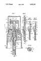
- FIG. 1is a vertical sectional view of a pump sprayer incorporating the precise output feature of the invention
- FIGS. 2 and 3are vertical, half sectional views of a portion of a prior art pump sprayer illustrating different travel distances of the open discharge valve during pumping;
- FIG. 4is a cross-sectional view taken substantially along the line 4--4 of FIG. 1;
- FIG. 5is a vertical sectional view of a portion of the FIG. 1 sprayer showing the uniform discharge valve open position achieved by the invention.
- a pump sprayergenerally designated 10 in FIG. 1, is constructed in essentially the same manner as the pump sprayer of my prior U.S. Pat. No. 4,051,983. The entirety of the disclosure thereof is therefore specifically incorporated herein by reference.
- the pump sprayercomprises a pump housing 11 which includes a first, upper relatively large diameter portion 12, and an axially aligned, relatively smaller diameter portion 13.
- a relatively large diameter pump piston member 14is disposed for reciprocation within body portion 12, and a relatively smaller diameter pump piston member 15 is disposed for reciprocation within body portion 13.
- Lower end 16 of the pump housingis adapted for communication with a supply of product to be dispensed from a container (not shown) through a dip tube 17 connected to end 16.
- the opposite or upper end of the pump bodyis open and is supported by a conventional closure which may be in the form of an internally threaded cap 18. Otherwise, the cap may be of the type so as to be snap-fitted in place over the container neck (not shown). And, the cap is adapted to support the pump body within the interior of the container to dispense the liquid product from the container as desired.
- the closure caphas a centrally domed portion 19 which defines an annular downwardly opening recess 21 which receives an upper annular end 22 of the pump body which is secured thereto, as by a suitable snap fit, to retain the pump body in its firmly supported position.
- the center of the caphas a central opening defined by a depending collar 23 through which a hollow piston rod 24 of the main or large piston 14 is disposed for reciprocation.
- the lower end of the large pistonis outwardly flared as at 25, and the free end of collar 23 has an internal enlargement 26 disposed for sealing against end 25 in the fully raised position of the piston 14 as shown in FIG. 1.
- a conventional spray type discharge head 27having a discharge spray orifice 28 communicating through suitable pasages 29 and 31 with the hollow piston rod for discharging the liquid product to the atmosphere in the form of a fine spray.
- An upper surface 32 of the discharge headis conformed to receive downward finger pressure for the purpose of reciprocating the main piston.
- the discharge headhas a depending cylindrical skirt 33 which is freely reciprocally received within an annular well 34 defined between generally vertical annular walls 35 and 36 formed on top of the closure cap. If desired, a conventional protective overcap 37 may be applied to and either snap fitted or friction fitted onto the lower end of outer wall 35, as shown.
- Hollow piston rod 24defines a discharge passage 38, and a small tube 39 is located on the inner wall of this passage, the tube defining a discharge port 41.
- a circular edge 42 at the inner end of this portdefines a discharge valve seat.
- This portis normally maintained closed by a discharge valve 44 with its upper end, conical or otherwise, bearing against valve seat 42.
- Discharge valve 44is in the form of an elongated solid valve stem carried by small diameter piston 15 for axial movement within hollow piston rod 24, the discharge valve normally being maintained in its closed or seated position by the resilient thrust of a coil spring 45 compressed between the lower piston and a shoulder 46 at lower end 16 of the pump body. However, discharge valve 44 may be unseated whenever the pressure within the pump body between pistons 14 and 15 exceeds the thrust of the spring.
- the two pistons and that part of the two diameter pump body encompassed between themdefine a variable volume pump chamber 47 of dual diameter.
- the small diameter pistonincludes a hollow piston rod 48 which is open for the reception of liquid product from the dip tube through an intake passage 49 controlled by a ball type check valve 51 for preventing back flow of liquid product from pump chamber 47 to the containter.
- the ball valveis housed and retained for operative movement within a valve cage 52 having a depending skirt 53 with internal axial ribs 54, through which liquid product delivered into the cage through inlet passage 49 may flow into the surrounding pump chamber 47. The liquid then flows upwardly into discharge passage 38 through the open discharge valve, and then through spray nozzle 28 into the atmosphere.
- the valve cageconstitutes an integral portion of the discharge valve which may be initially formed separately from small diameter piston 15, but which is suitably secured over the upper end of the appropriately formed and proportioned lower piston rod 48, as shown.
- resiliently flexible skirts 55 and 56 of these pistonswill normally be made to extend in opposite relation.
- resiliently flexible skirt 55 of the large diameter pistonhas its free edge directed downwardly
- the resiliently flexible skirt 56 of the small diameter pistonhas its free edge directed upwardly, the arrangement being well known such that fluid pressure acting against these skirts within the pump chamber will urge them radially outwardly into sliding fluid tight engagement with the cylinder walls.
- the pumpis also provided with a suitable valve controlled container vent for equalizing the pressures within and outside the container when the pump is in operation, and for interrupting such communication when the pump is in its storage or other position of non-use, to thereby prevent leakage or loss of contents.
- a suitable valve controlled container ventfor equalizing the pressures within and outside the container when the pump is in operation, and for interrupting such communication when the pump is in its storage or other position of non-use, to thereby prevent leakage or loss of contents.
- the priming valve structure of the U.S. Pat. No. 4,051,983may likewise be adopted for the present pump sprayer in that a small ramp or protuberance 58 is provided on the inner wall of small diameter portion 13 so as to engage and inwardly deflect a localized portion of lower piston skirt 56, when such piston is at or near the lower extremity of its downward stroke. A downward flow of entrapped air from pump chamber 47 is thereby permitted to flow into lower portion 13, through dip tube 17 and back into the container. Further details of the construction of protuberance 58 and the accompanying priming feature of U.S. Pat. No. 4,051,983, are omitted for the sake of brevity.
- the degree of compression of liquid product within the pump chamberwill be such that the amount of thrust transmitted to the small diameter piston will exceed the upward thrust of spring 45, with the result that the small diameter piston will move downwardly at a higher velocity as compared to the large diameter piston.
- This in turnwill cause discharge valve 44 to open as it moves away from its valve seat 42, and to remain open as long as such differential pressure is maintained, during which time the liquid product is discharged through the open discharge passage 38 and the spray discharge nozzle. If the pressure drops, however, the discharge valve is automatically closed by the spring pressure to prevent discharge of liquid at a predetermined pressure below that desired.
- FIG. 2illustrates the separation distance x of the discharge valve just prior to or at the bottoming out of piston 14.
- the length of the large diameter piston strokemay be shorter during pumping so as not to bottom out.
- the swept volume of pressurized product within large diameter pump body portion 12will be discharged through the open discharge passage and discharge orifice, plus the swept volume of pressurized product within the small diameter pump body portion 13 as the discharge valve moves upwardly through a distance y until it reseats against its discharge valve seat. Since the distance y is greater than the distance x, it can be seen that a slightly greater volume of product is expelled from the pump chamber upon application of a relatively heavier finger pressure (FIG. 3) as compared to the application of a relatively lighter finger pressure (FIG. 2). This difference in volume of discharged product is quite acceptable for most applications of liquid products such as detergents, starches, window cleaners, etc.
- the inventionsimply provides for limiting the travel of the small diameter piston and its discharge valve after the discharge valve shifts into an open position away from its valve seat.
- Such travel limitation of the small diameter pistonis effected by the provision of at least one inwardly projecting lug 59 located on inner wall 61 of hollow piston rod 24 which may be located upstream of the discharge valve seat.
- lugssuch as a total of four, may be so provided as equally spaced for stability.
- each of the lugsmay have a sloping upper surface as shown in FIG. 1.
- An annular lip 62projects outwardly of discharge valve stem 44, the lip having an outer diameter less than the diameter of inner wall 61 so as to avoid any disruption of flow of pressurized product from the pump chamber during discharge. And, the lip is axially spaced in the FIG. 1 position a sufficient distance from the lugs such that, in the valve open position of FIG. 5, lip 62 will engage the lugs to thereby limit the opening of the discharge valve to a minimum distance a, shown in this Figure.
- the surface of lip 62 which confronts the sloping surfaces of lugs 59may be similarly sloped for smooth engagement therewith as the difference in pressure between the product in the pump chamber and the return spring force causes the small diameter piston to shift into its FIG. 5 position.
- the discharge valveupon application of either a slight finger pressure on the spray discharge head, or a relatively heavy finger pressure thereon, the discharge valve will be shifted open a distance small a sufficient to permit the discharge of pressurized product equal to the swept volume of pump body portion 12 as the main piston bottoms out as shown in FIG. 5, plus the swept volume of product in body portion 13 as the small diameter piston shifts upwardly through a distance a back into its valve closed position.
- This volume of discharged productis consistent and constant for each full stroke of the main piston during the pumping of the same product, irrespective of light or heavy finger pressures applied to the spray discharge head.
- the cooperating limit stops 59 and 62assure the precise output of product since the combined volume of discharge from the pressure chamber which is delimited by the large and small diameter pistons, is always the same.
- the cooperating limits stops provided for limiting the separation distance of the discharge valve member during pumpingthereby limits the duration during which the discharge passage is open during pumping irrespective of different external reciprocating pressures applied, such that the output of the sprayer is controlled during pumping in a simple and efficient yet highly effective manner.
- Equivalent cooperating limit stopsmay be provided without departing from the invention, and the cooperating stops may respectively be located on hollow piston rod 24 and the discharge valve stem at locations other than illustrated in the drawings, so long as the cooperating limit stops are initially spaced apart axially in the valve closed position a distance sufficient to limit the shifted open position of the discharge valve to at least a minimum distance from its valve seat.
- a number of limit lugsmay be provided other than that aforedescribed, in addition to at least one.
Landscapes
- Reciprocating Pumps (AREA)
Abstract
Description
Claims (4)
Priority Applications (1)
| Application Number | Priority Date | Filing Date | Title |
|---|---|---|---|
| US06/847,453US4692103A (en) | 1986-04-03 | 1986-04-03 | Precise output pump sprayer |
Applications Claiming Priority (1)
| Application Number | Priority Date | Filing Date | Title |
|---|---|---|---|
| US06/847,453US4692103A (en) | 1986-04-03 | 1986-04-03 | Precise output pump sprayer |
Publications (1)
| Publication Number | Publication Date |
|---|---|
| US4692103Atrue US4692103A (en) | 1987-09-08 |
Family
ID=25300660
Family Applications (1)
| Application Number | Title | Priority Date | Filing Date |
|---|---|---|---|
| US06/847,453Expired - Fee RelatedUS4692103A (en) | 1986-04-03 | 1986-04-03 | Precise output pump sprayer |
Country Status (1)
| Country | Link |
|---|---|
| US (1) | US4692103A (en) |
Cited By (22)
| Publication number | Priority date | Publication date | Assignee | Title |
|---|---|---|---|---|
| US4842495A (en)* | 1986-10-24 | 1989-06-27 | Bespak Plc | Non throttling discharge pump assembly |
| GB2231097A (en)* | 1989-01-13 | 1990-11-07 | Bosch Gmbh Robert | Hand-operated pump for a feed pump of a fuel injection system for an internal combustion engine |
| US5020696A (en)* | 1989-11-27 | 1991-06-04 | Rjs Industries, Inc. | Atomizing fluid dispenser two |
| US5046644A (en)* | 1989-11-27 | 1991-09-10 | American Dispensing Systems Inc. | Atomizing fluid dispenser one |
| WO1993019406A1 (en)* | 1992-03-16 | 1993-09-30 | Wagner Spray Tech Corporation | Improved pwm control for electric motor driven piston paint pumps |
| FR2705537A1 (en)* | 1993-05-25 | 1994-12-02 | Joung Whayong | Artificial flower which releases a perfume |
| US5401148A (en)* | 1994-04-15 | 1995-03-28 | Contico International, Inc. | Manually operated reciprocating liquid pump |
| US5560520A (en)* | 1995-08-07 | 1996-10-01 | Calmar Inc. | Precompression pump sprayer |
| US5687878A (en)* | 1994-04-15 | 1997-11-18 | Owens-Brockway Plastic Products Inc. | Flexible tube with pump dispenser and method of making |
| US5715973A (en)* | 1996-02-01 | 1998-02-10 | Contico International, Inc. | Manually operated fluid pump for dispensing lotion and the like |
| US5775547A (en)* | 1996-10-07 | 1998-07-07 | Continental Sprayers Internatioal, Inc. | Lotion dispensing pump with sealing plug for sealing pump chamber |
| US5794821A (en)* | 1996-05-07 | 1998-08-18 | Contico International, Inc. | Reciprocating liquid pump with disc check valve for dispensing lotion and the like |
| US5800770A (en)* | 1994-04-15 | 1998-09-01 | Owens-Brockway Plastic Products Inc. | Method of making a flexible tube |
| US5884205A (en)* | 1996-08-22 | 1999-03-16 | Dickey-John Corporation | Boom configuration monitoring and control system for mobile material distribution apparatus |
| US5897600A (en)* | 1996-08-22 | 1999-04-27 | Elmore; Thomas R. | Universal modular control system for mobile material distribution apparatus |
| US5911362A (en)* | 1997-02-26 | 1999-06-15 | Dickey-John Corporation | Control system for a mobile material distribution device |
| US5947340A (en)* | 1995-12-06 | 1999-09-07 | The Procter & Gamble Company | Manually-actuated high pressure spray pump |
| US5964377A (en)* | 1997-10-14 | 1999-10-12 | S. C. Johnson & Son, Inc. | Manually operable pump for mixing and dispensing primary and secondary fluids |
| US5988443A (en)* | 1994-04-15 | 1999-11-23 | Owens-Brockway Plastic Products Inc. | Flexible tube with pump dispenser and method of making |
| US20060011659A1 (en)* | 2004-07-13 | 2006-01-19 | Juergen Greiner-Perth | Dispenser for media |
| US20060011663A1 (en)* | 2004-07-13 | 2006-01-19 | Juergen Greiner-Perth | Metering apparatus for media |
| JP2023097140A (en)* | 2021-12-27 | 2023-07-07 | 株式会社吉野工業所 | ejector |
Citations (5)
| Publication number | Priority date | Publication date | Assignee | Title |
|---|---|---|---|---|
| US4051983A (en)* | 1975-11-19 | 1977-10-04 | Diamond International Corporation | Pump sprayer |
| US4088425A (en)* | 1977-01-10 | 1978-05-09 | Bennett Robert A | Manually operated pump for disposable container |
| US4147476A (en)* | 1974-03-28 | 1979-04-03 | Bespak Industries Limited | Pump assembly for an atomizing piston pump |
| US4245967A (en)* | 1977-09-16 | 1981-01-20 | Establissements Valois | Pump for a hand actuated device for producing an atomized spray |
| US4344744A (en)* | 1979-01-24 | 1982-08-17 | Pfeiffer Zerstaubervertriebsgesellschaft mbH & Co. KG | Spray pump |
- 1986
- 1986-04-03USUS06/847,453patent/US4692103A/ennot_activeExpired - Fee Related
Patent Citations (6)
| Publication number | Priority date | Publication date | Assignee | Title |
|---|---|---|---|---|
| US4147476A (en)* | 1974-03-28 | 1979-04-03 | Bespak Industries Limited | Pump assembly for an atomizing piston pump |
| US4051983A (en)* | 1975-11-19 | 1977-10-04 | Diamond International Corporation | Pump sprayer |
| US4051983B1 (en)* | 1975-11-19 | 1993-12-14 | Calmar Inc. | Pump sprayer having pump priming means |
| US4088425A (en)* | 1977-01-10 | 1978-05-09 | Bennett Robert A | Manually operated pump for disposable container |
| US4245967A (en)* | 1977-09-16 | 1981-01-20 | Establissements Valois | Pump for a hand actuated device for producing an atomized spray |
| US4344744A (en)* | 1979-01-24 | 1982-08-17 | Pfeiffer Zerstaubervertriebsgesellschaft mbH & Co. KG | Spray pump |
Cited By (27)
| Publication number | Priority date | Publication date | Assignee | Title |
|---|---|---|---|---|
| US4842495A (en)* | 1986-10-24 | 1989-06-27 | Bespak Plc | Non throttling discharge pump assembly |
| GB2231097A (en)* | 1989-01-13 | 1990-11-07 | Bosch Gmbh Robert | Hand-operated pump for a feed pump of a fuel injection system for an internal combustion engine |
| GB2231097B (en)* | 1989-01-13 | 1992-12-02 | Bosch Gmbh Robert | Hand-operated pump for a feed pump of a fuel injection system for an internal combustion engine |
| US5020696A (en)* | 1989-11-27 | 1991-06-04 | Rjs Industries, Inc. | Atomizing fluid dispenser two |
| US5046644A (en)* | 1989-11-27 | 1991-09-10 | American Dispensing Systems Inc. | Atomizing fluid dispenser one |
| US6031352A (en)* | 1992-03-16 | 2000-02-29 | Wagner Spray Tech Corporation | Active alternator load circuit |
| WO1993019406A1 (en)* | 1992-03-16 | 1993-09-30 | Wagner Spray Tech Corporation | Improved pwm control for electric motor driven piston paint pumps |
| FR2705537A1 (en)* | 1993-05-25 | 1994-12-02 | Joung Whayong | Artificial flower which releases a perfume |
| US5687878A (en)* | 1994-04-15 | 1997-11-18 | Owens-Brockway Plastic Products Inc. | Flexible tube with pump dispenser and method of making |
| US6127011A (en)* | 1994-04-15 | 2000-10-03 | Owens-Brockway Plastics Products Inc. | Flexible tube and method of making |
| US5401148A (en)* | 1994-04-15 | 1995-03-28 | Contico International, Inc. | Manually operated reciprocating liquid pump |
| US5988443A (en)* | 1994-04-15 | 1999-11-23 | Owens-Brockway Plastic Products Inc. | Flexible tube with pump dispenser and method of making |
| US5800770A (en)* | 1994-04-15 | 1998-09-01 | Owens-Brockway Plastic Products Inc. | Method of making a flexible tube |
| US5560520A (en)* | 1995-08-07 | 1996-10-01 | Calmar Inc. | Precompression pump sprayer |
| US5947340A (en)* | 1995-12-06 | 1999-09-07 | The Procter & Gamble Company | Manually-actuated high pressure spray pump |
| US6050457A (en)* | 1995-12-06 | 2000-04-18 | The Procter & Gamble Company | High pressure manually-actuated spray pump |
| US5715973A (en)* | 1996-02-01 | 1998-02-10 | Contico International, Inc. | Manually operated fluid pump for dispensing lotion and the like |
| US5927561A (en)* | 1996-05-07 | 1999-07-27 | Continental Sprayers International, Inc. | Reciprocating liquid pump with disc check valve for dispensing lotion and the like |
| US5794821A (en)* | 1996-05-07 | 1998-08-18 | Contico International, Inc. | Reciprocating liquid pump with disc check valve for dispensing lotion and the like |
| US5897600A (en)* | 1996-08-22 | 1999-04-27 | Elmore; Thomas R. | Universal modular control system for mobile material distribution apparatus |
| US5884205A (en)* | 1996-08-22 | 1999-03-16 | Dickey-John Corporation | Boom configuration monitoring and control system for mobile material distribution apparatus |
| US5775547A (en)* | 1996-10-07 | 1998-07-07 | Continental Sprayers Internatioal, Inc. | Lotion dispensing pump with sealing plug for sealing pump chamber |
| US5911362A (en)* | 1997-02-26 | 1999-06-15 | Dickey-John Corporation | Control system for a mobile material distribution device |
| US5964377A (en)* | 1997-10-14 | 1999-10-12 | S. C. Johnson & Son, Inc. | Manually operable pump for mixing and dispensing primary and secondary fluids |
| US20060011659A1 (en)* | 2004-07-13 | 2006-01-19 | Juergen Greiner-Perth | Dispenser for media |
| US20060011663A1 (en)* | 2004-07-13 | 2006-01-19 | Juergen Greiner-Perth | Metering apparatus for media |
| JP2023097140A (en)* | 2021-12-27 | 2023-07-07 | 株式会社吉野工業所 | ejector |
Similar Documents
| Publication | Publication Date | Title |
|---|---|---|
| US4692103A (en) | Precise output pump sprayer | |
| US4051983A (en) | Pump sprayer | |
| US4189064A (en) | Pumps sprayer | |
| US4640443A (en) | Manually operated dispensing pump | |
| US4173297A (en) | Non-throttling manually reciprocated plunger pump for consumer-type liquid dispensing containers | |
| US4591077A (en) | Continuous discharge dispenser | |
| US4402432A (en) | Leak-proof dispensing pump | |
| US5092495A (en) | Precompression pump for spray discharge of a liquid | |
| US5720419A (en) | Pre-compression pump sprayer having improved inlet and discharge valving and an improved pump priming feature | |
| US5181635A (en) | Liquid pump dispenser having a stationary spout | |
| US4494680A (en) | Manually operated dispensing pump | |
| US5353969A (en) | Invertible pump sprayer having spiral vent path | |
| CA1144119A (en) | Accumulative pressure pump | |
| EP0145155B1 (en) | Dispenser for a flowable product | |
| US4033487A (en) | Double trigger pump | |
| US5242089A (en) | Miniature pump sprayer | |
| US4022354A (en) | Accumulator release pump | |
| EP0374348B1 (en) | Improved precompression pump, for dispensing liquid products from vessels | |
| JPH04267962A (en) | Fluid product spraying or distributing device for drawing in fluid product in exit passage at the end of operation | |
| CA1230867A (en) | Dispensing pump adapted for pressure filling | |
| US4437588A (en) | Accumulative pressure pump | |
| EP0128585B1 (en) | Hand manipulatable sprayer | |
| US5277341A (en) | Device for spraying a fluid by means of a pump that is actuated repeatedly by a solenoid | |
| US4053086A (en) | Pumps for hand-held dispensers | |
| US7717302B2 (en) | Pump and a receptacle fitted therewith |
Legal Events
| Date | Code | Title | Description |
|---|---|---|---|
| AS | Assignment | Owner name:CALMAR, INC., 333 SOUTH TURNBULL CANYON ROAD, CITY Free format text:ASSIGNMENT OF ASSIGNORS INTEREST.;ASSIGNOR:ANDERSON, WALTER F.;REEL/FRAME:004555/0141 Effective date:19860311 | |
| AS | Assignment | Owner name:CITICORP NORTH AMERICA, INC., AS AGENT, CALIFORNIA Free format text:SECURITY INTEREST;ASSIGNOR:CALMAR INC.;REEL/FRAME:005020/0974 Effective date:19881208 | |
| FPAY | Fee payment | Year of fee payment:4 | |
| AS | Assignment | Owner name:UNITED STATES TRUST COMPANY OF NEW YORK, NEW YORK Free format text:SECURITY INTEREST;ASSIGNOR:CALMAR INC.;REEL/FRAME:006608/0452 Effective date:19911223 | |
| AS | Assignment | Owner name:CALMAR INC., A CORPORATION OF DELAWARE, CALIFORNIA Free format text:RELEASE BY SECURED PARTY OF A SECURITY AGREEMENT RECORDED AT REEL 5020 FRAME 0974 AND DATED 12-08-88;ASSIGNOR:CITICORP NORTH AMERICA, INC.;REEL/FRAME:006082/0535 Effective date:19911212 | |
| FPAY | Fee payment | Year of fee payment:8 | |
| AS | Assignment | Owner name:MELLON BANK, N.A., AS COLLATERAL AGENT, PENNSYLVAN Free format text:PATENT COLLATERAL SECURITY AGREEMENT;ASSIGNOR:CALMAR INC., A DELAWARE CORPORATION;REEL/FRAME:007662/0551 Effective date:19950918 Owner name:CALMAR INC., A DE CORP., CALIFORNIA Free format text:TERMINATION AND RELEASE OF INTELLECTUAL PROPERTY PLEDGE AGREEMENT;ASSIGNOR:UNITED STATES TRUST COMPANY OF NEW YORK, AS COLLATERAL AGENT;REEL/FRAME:007648/0338 Effective date:19950918 | |
| AS | Assignment | Owner name:BANQUE INDOSUEZ, AS COLLATERAL AGENT, NEW YORK Free format text:SECURITY INTEREST;ASSIGNOR:MELLON BANK, N.A., AS COLLATERAL AGENT;REEL/FRAME:008186/0912 Effective date:19961025 | |
| FEPP | Fee payment procedure | Free format text:PAYOR NUMBER ASSIGNED (ORIGINAL EVENT CODE: ASPN); ENTITY STATUS OF PATENT OWNER: LARGE ENTITY | |
| AS | Assignment | Owner name:CALMAR, INC., CALIFORNIA Free format text:TERMINATION OF PATENT SECURITY INTERESTS;ASSIGNOR:BANQUE INDOSUEZ, AS COLLATERAL AGENT;REEL/FRAME:009375/0018 Effective date:19980722 | |
| FEPP | Fee payment procedure | Free format text:PAYER NUMBER DE-ASSIGNED (ORIGINAL EVENT CODE: RMPN); ENTITY STATUS OF PATENT OWNER: LARGE ENTITY | |
| REMI | Maintenance fee reminder mailed | ||
| LAPS | Lapse for failure to pay maintenance fees | ||
| FP | Lapsed due to failure to pay maintenance fee | Effective date:19990908 | |
| STCH | Information on status: patent discontinuation | Free format text:PATENT EXPIRED DUE TO NONPAYMENT OF MAINTENANCE FEES UNDER 37 CFR 1.362 |