US4691705A - Calculus crushing apparatus - Google Patents
Calculus crushing apparatusDownload PDFInfo
- Publication number
- US4691705A US4691705AUS06/822,019US82201986AUS4691705AUS 4691705 AUS4691705 AUS 4691705AUS 82201986 AUS82201986 AUS 82201986AUS 4691705 AUS4691705 AUS 4691705A
- Authority
- US
- United States
- Prior art keywords
- sheath
- basket
- distal end
- calculus
- flexible
- Prior art date
- Legal status (The legal status is an assumption and is not a legal conclusion. Google has not performed a legal analysis and makes no representation as to the accuracy of the status listed.)
- Expired - Lifetime
Links
- 230000008602contractionEffects0.000claims1
- 230000008878couplingEffects0.000description12
- 238000010168coupling processMethods0.000description12
- 238000005859coupling reactionMethods0.000description12
- 210000000013bile ductAnatomy0.000description8
- 230000037431insertionEffects0.000description8
- 238000003780insertionMethods0.000description8
- 230000002093peripheral effectEffects0.000description7
- 230000002183duodenal effectEffects0.000description4
- 239000007788liquidSubstances0.000description3
- 239000000463materialSubstances0.000description3
- 238000010276constructionMethods0.000description2
- 230000009977dual effectEffects0.000description2
- 101100008046Caenorhabditis elegans cut-2 geneProteins0.000description1
- 239000004809TeflonSubstances0.000description1
- 229920006362Teflon®Polymers0.000description1
- 230000002411adverseEffects0.000description1
- 230000004323axial lengthEffects0.000description1
- 238000005452bendingMethods0.000description1
- 238000006243chemical reactionMethods0.000description1
- 239000002872contrast mediaSubstances0.000description1
- 230000000694effectsEffects0.000description1
- 229920000642polymerPolymers0.000description1
- 229920005989resinPolymers0.000description1
- 239000011347resinSubstances0.000description1
- 229920003002synthetic resinPolymers0.000description1
- 239000000057synthetic resinSubstances0.000description1
- 210000001835visceraAnatomy0.000description1
Images


Classifications
- A—HUMAN NECESSITIES
- A61—MEDICAL OR VETERINARY SCIENCE; HYGIENE
- A61B—DIAGNOSIS; SURGERY; IDENTIFICATION
- A61B17/00—Surgical instruments, devices or methods
- A61B17/22—Implements for squeezing-off ulcers or the like on inner organs of the body; Implements for scraping-out cavities of body organs, e.g. bones; for invasive removal or destruction of calculus using mechanical vibrations; for removing obstructions in blood vessels, not otherwise provided for
- A61B17/221—Gripping devices in the form of loops or baskets for gripping calculi or similar types of obstructions
- A—HUMAN NECESSITIES
- A61—MEDICAL OR VETERINARY SCIENCE; HYGIENE
- A61B—DIAGNOSIS; SURGERY; IDENTIFICATION
- A61B17/00—Surgical instruments, devices or methods
- A61B2017/00831—Material properties
- A61B2017/00853—Material properties low friction, hydrophobic and corrosion-resistant fluorocarbon resin coating (ptf, ptfe, polytetrafluoroethylene)
- A—HUMAN NECESSITIES
- A61—MEDICAL OR VETERINARY SCIENCE; HYGIENE
- A61B—DIAGNOSIS; SURGERY; IDENTIFICATION
- A61B17/00—Surgical instruments, devices or methods
- A61B17/22—Implements for squeezing-off ulcers or the like on inner organs of the body; Implements for scraping-out cavities of body organs, e.g. bones; for invasive removal or destruction of calculus using mechanical vibrations; for removing obstructions in blood vessels, not otherwise provided for
- A61B17/221—Gripping devices in the form of loops or baskets for gripping calculi or similar types of obstructions
- A61B2017/2212—Gripping devices in the form of loops or baskets for gripping calculi or similar types of obstructions having a closed distal end, e.g. a loop
Definitions
- the present inventionrelates to a calculus crushing apparatus for crushing a calculus produced in the body cavity.
- calculus crushing apparatuseshave conventionally been developed which are inserted into the body cavity through an endoscope. These apparatuses are used to crush or completely remove a calculus in the body cavity from the cavity.
- a catch basket formed of resilient wiresis fixed to the distal end of an operating wire, and the operating wire, along with the basket, is inserted into a flexible sheath having a rigid portion at its distal end.
- the basketis spread or folded by advancing or retreating the operating wire at the rear end of the sheath. After seizing the calculus by means of the basket projecting from the distal end of the sheath, the operating wire is pulled to draw the basket into the sheath. Thus, the basket is folded to break the calculus therein into small pieces.
- the flexible sheathis formed of a close coil or other suitable material which is strong enough to stand a force applied thereto during a calculus crushing operation.
- the close coilis extremely stable and exhibits strong resistance to bending. Therefore, the sheath cannot easily be inserted into curved regions of a body cavity, e.g., into the bile duct via the duodenal papilla, and may possibly injure or puncture the body wall during the insertion.
- the present inventionis contrived in consideration of these circumstances, and is intended to provide a calculus crushing apparatus capable of being inserted into curved portions of a body cavity without injuring the body wall as well as reliably crushing calculi.
- a flexible sheathincludes a first sheath having a predetermined strength and a second sheath which is weaker but more flexible than the first sheath.
- the first and second sheathscan be moved relatively between a position where the first sheath extends beyond the distal end of the second sheath, and a position where the second sheath projects sufficiently beyond the distal end of the first sheath.
- the second sheathwhich is more flexible, is extended beyond the distal end of the first one.
- the first sheathis extended farther.
- FIGS. 1 to 7show a calculus crushing apparatus according to a first embodiment of the present invention, in which
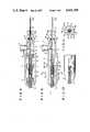
- FIG. 1is a cutaway, general side view of the apparatus
- FIG. 2is a sectional view showing a flexible sheath and a mouthpiece
- FIG. 3is a sectional view similar to FIG. 2, showing an operating state different from the one shown in FIG. 2,
- FIG. 4is a sectional view taken along line IV--IV of FIG. 1,
- FIG. 5is a sectional view taken along line V--V of FIG. 1,
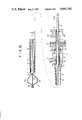
- FIG. 6is a schematic view showing a situation in which the sheath in the state of FIG. 2 is inserted in the body cavity
- FIG. 7is a schematic view showing a situation in which the sheath in the state of FIG. 3 is inserted in the body cavity;
- FIG. 8is a sectional view showing a proximal end portion of a sheath of a crushing apparatus according to a second embodiment of the invention.
- FIGS. 9 to 11show a third embodiment of the invention, in which
- FIG. 9is a sectional view showing a proximal end portion of a flexible sheath and a mouthpiece
- FIG. 10is a plan view of the proximal end portion of the sheath.
- FIG. 11is a sectional view taken along line XI--XI of FIG. 9.
- FIG. 12is a sectional view showing a flexible sheath and a mouthpiece of a crushing apparatus according to a fourth embodiment of the invention.
- a calculus crushing apparatuscomprises elongate flexible sheath 1 adapted to be inserted into the body cavity and mouthpiece 7 attached to the proximal end of sheath 1, as shown in FIG. 1.
- An operating wireas described in detail later, is inserted in sheath 1.
- Basket 17 for seizing a foreign objectis coupled to the distal end of the wire, projecting from the distal end of sheath 1.
- Mouthpiece 7is connected to operating section 25 for pushing and pulling the wire.
- sheath 1is of dual structure, including first sheath 1a and second sheath 1b inserted in the first one. Sheaths 1a and 1b are movable relative to the other. Sheath 1a is formed of a close coil which is strong enough to stand a force applied thereto during calculus crushing operation. Cylindrical rigid member 3 with wire escape cut 2 is fixed to the distal end of sheath 1a, while cylindrical retaining member 4 is fixed around the proximal end portion of sheath 1a. External threaded portion 4a is formed on the outer peripheral surface of member 4. Member 4 is movably housed in holding cylinder 5 which is arranged around the proximal end portion of sheath 1a.
- Internal threaded portion 6 to engage threaded portion 4a of member 4is formed on the inner surface of the front end of cylinder 5.
- Cylinder 5is rotatably mounted on mouthpiece 7.
- Mouthpiece 7includes first and second members 8 and 12 engaging each other. Boss portion 9 protrudes forward from first member 8. The rear end of holding cylinder 5 is rotatably supported, in a liquid-tight manner, on the outer peripheral surface of portion 9 through O-ring 10.
- Mouthpiece 7has through hole 13 extending through first and second members 8 and 12 and boss portion 9, and liquid feed port 11 communicating with hole 13.
- First sheath 1ais penetrated by second sheath 1b which is weaker but more flexible than sheath 1a.
- Sheath 1bis formed of a flexible resin, such as fluorine-contained polymer, Teflon, etc.
- One end of connecting pipe 15is fixedly inserted in through hole 13 of boss portion 9 of mouthpiece 7 so that pipe 15 projects forward from portion 9.
- the proximal end portion of sheath 1bis fitted on the projecting end portion of pipe 15 in a liquid-tight manner.
- first sheath 1ais slidably mounted on second sheath 1b.
- sheath 1aWhen sheath 1a is slid forward so that retaining member 4 fixed on the proximal end of sheath 1a is screwed in threaded portion 6 of holding cylinder 5, sheath 1a is held in a position where its distal end extends beyond that of sheath 1b, as shown in FIG. 3.
- operating wire 16is slidably passed through second sheath 1b.
- Basket 17 for seizing and crushing a calculus or other foreign objectis coupled to the distal end of wire 16.
- Basket 17is formed by coupling a plurality of resilient wires 18 to one another at both the front and rear ends thereof by means of front and rear tips 19, respectively. Bent portions 20 is formed in the middle of each wire 18.
- Bent portions 20is formed in the middle of each wire 18.
- basket 17can extend and contract or is collapsible in the axial direction of operating wire 16.
- the distal end of straight, elongate coupling rod 21is fixed to the proximal end of wire 16.
- Rod 21is slidably passed through hole 13 of mouthpiece 7, extending rearward from the mouthpiece.
- O-ring 22is disposed at the junction between first and second members 8 and 12 of mouthpiece 7, whereby through hole 13 is kept liquid-tight.
- Rod 21penetrates ring 22.
- a liquid, such as a contrast medium,can be fed into second sheath 1b through liquid feed port 11.
- First support shaft 43is rotatably supported in body 26 of operating section 25 by means of bearings 44, extending at right angles to rack structure 31.
- First gear 45is fixed on one end of shaft 45, while knob 46 is mounted on the other end outside body 26.
- second support shaft 47is rotatably supported in body 26 by means of bearings 48, extending parallel to shaft 43.
- Shaft 47is fixedly fitted, at one end thereof, with second gear 49 which engages first gear 45. There are more teeth on the second gear than on the first one.
- Cavity 50is formed in body 26, opening into insertion hole 28. Shaft 47 extends through cavity 50.
- Cavity 50contains third gear 51 which is fixed on shaft 47 and meshed with rack 32. If knob 46 is rotated, therefore, the rotation is decelerated by first and second gears 45 and 49 and transmitted to third gear 51. Then, gear 51 causes rack structure 31 to slide, thus moving operating wire 16 through the medium of coupling rod 21.
- sheath 1bis inserted into, for example, bile duct 58 through duodenal papilla 57.
- sheath 1bcan be bent easily and produces only a small reaction force when bent. Therefore, it will not injure duodenal papilla 57 or bile duct 58.
- Second sheath 1bis inserted into bile duct 58, coupling rod 21 is pushed in to advance operating wire 16, thereby projecting basket 17 from the distal end of sheath 1b to spread the basket. Basket 17 is then manipulated to catch calculus 59 in duct 58. If calculus 59 is relatively small, it can be removed by drawing out sheath 1 and the endoscope from the body cavity with the calculus in basket 17.
- first sheath 1ais first advanced along second sheath 1b and inserted into duct 58, as shown in FIG. 7. As a result, the distal end of sheath 1a extends beyond that of sheath 1b. Then, retaining member 4 is screwed into treaded portion 6 of holding cylinder 5 to prevent sheath 1a from sliding, thus locking sheath 1a to the position shown in FIGS. 3 and 7.
- First sheath 1ais strong enough to stand the calculus crushing operation, but is less flexible than second sheath 1b.
- sheath 1acan be inserted into bile duct 58 in a bent configuration maintained securely, guided by sheath 1b. Accordingly, there is no possibility of sheath 1a injuring duodenal papilla 57 or bile duct 58.
- coupling rod 21is pulled to retreat operating wire 16.
- basket 17is folded by rigid member 3 at the distal end of sheath 1a, so that calculus 59 in basket 17 is broken into pieces by resilient wires 18 which constitute the basket.
- Calculus 59may be crushed by pulling coupling rod 21 by means of operating section 25 connected to mouthpiece 7, instead of manually pulling rod 21.
- rod 21is backed by means of rack structure 31 if knob 46 is rotated.
- section 25the rotation of handle 46 is slowed down but amplified as it is transmitted to rod 21.
- calculus 59can be crushed gradually with a small force.
- the flexible sheathhas a dual structure, comprising first sheath 1a having a predetermined strength and second sheath 1b weaker but more flexible than the first one.
- Sheaths 1a and 1bare movable relative to each other between a position where the distal end of the first sheath extends beyond that of the second one, and a position where the second sheath projects sufficiently beyond the distal end of the first one. If the second sheath is kept projected from the distal end of the first sheath when flexible sheath 1 is inserted into the body cavity, the flexibility of the second sheath serves to facilitate the insertion.
- the first sheathis moved to the position where its distal end is located beyond that of the second sheath.
- the first sheathcan securely accomplish the crushing operation.
- FIG. 8shows a second embodiment of the present invention. This embodiment differs from the first embodiment in the construction of support means for holding cylinder 5.
- Ring-shaped flange 61is formed at the proximal end portion of cylinder 5, and boss portion 9 of mouthpiece 7 is inserted through hole 61a which is defined by the inner peripheral surface of flange 61.
- Ring-shaped stopper 62is fixed on the outer surface of portion 9, facing flange 61.
- FIGS. 9, 10 and 11show a third embodiment of the invention.
- This embodimentdiffers from the first embodiment in the construction of retaining means for holding first sheath 1a in position.
- Retaining member 4includes, in place of the external threaded portion, a pair of arms 69 which protrude diametrically outward. Arms 69 are spaced at intervals of 180 degrees in the circumferential direction of member 4.
- the proximal end of holding cylinder 5is fixed to boss portion 9 of mouthpiece 7. Instead of the internal threaded portion, moreover, a pair of slide grooves 66 are formed on cylinder 5, extending in the axial direction thereof.
- Grooves 66are spaced at intervals of 180 degrees in the circumferential direction of cylinder 5, and open to the distal end of cylinder 5. Also, cylinder 5 is formed with a pair of engaging slots 67a extending in the circumferential direction of cylinder 5 and opening into one of grooves 66, and another pair of engaging slots 67b extending in the same direction and opening into the other groove. Slots 67a are spaced along the axis of cylinder 5, while slots 67b are spaced at intervals equal to those between slots 67a along the cylinder axis. Also, slots 67a and 67b are opposed to one another. Arms 69 of retaining member 4 are slidably inserted in their corresponding slide grooves 66, and can engage engaging slots 67a and 67b.
- first sheath 1acan be locked in a predetermined position by advancing retaining member 4 to a position where arms 69 face their corresponding engaging slots 67a and 67b, and then rocking member 4 to cause the arms to engage the slots.
- FIG. 12shows a fourth embodiment of the present invention.
- first and second sheaths 1a and 1bare positioned in reverse to those of the first embodiment.
- first sheath 1a formed of a close coilis inserted in flexible second sheath 1b formed of synthetic resin or the like.
- Operating wire 16is inserted in sheath 1a.
- the proximal end of sheath 1bis fitted on boss portion 9 of mouthpiece 7.
- the proximal end of sheath 1ais coupled to guide pipe 71 which is slidably inserted into through hole 13 of mouthpiece 7, projecting rearward therefrom.
- Coupling rod 21 connected to the proximal end of wire 16extends through pipe 71.
- Ring-shaped retaining member 4 having external threaded portion 4a on its outer peripheral surfaceis fixed on the proximal end portion of pipe 71.
- Engaging groove 12a for coupling member 4 to the operating sectionis formed on the outer peripheral surface of member 4.
- Holding cylinder 5is rotatably mounted on the rear end portion of mouthpiece 7, and internal threaded portion 6 to engage threaded portion 4a of retaining member 4 is formed on the inner peripheral surface of cylinder 5.
- First sheath 1ais moved inside second sheath 1b by advancing or retreating guide pipe 71 and retaining member 4.
- Sheath 1acan be prevented from sliding by advancing it so that its distal end projects beyond the distal end of sheath 1b, and then screwing member 4 into holding cylinder 5.
Landscapes
- Health & Medical Sciences (AREA)
- Surgery (AREA)
- Life Sciences & Earth Sciences (AREA)
- Heart & Thoracic Surgery (AREA)
- Nuclear Medicine, Radiotherapy & Molecular Imaging (AREA)
- Vascular Medicine (AREA)
- Engineering & Computer Science (AREA)
- Biomedical Technology (AREA)
- Orthopedic Medicine & Surgery (AREA)
- Medical Informatics (AREA)
- Molecular Biology (AREA)
- Animal Behavior & Ethology (AREA)
- General Health & Medical Sciences (AREA)
- Public Health (AREA)
- Veterinary Medicine (AREA)
- Surgical Instruments (AREA)
Abstract
Description
Claims (8)
Applications Claiming Priority (2)
| Application Number | Priority Date | Filing Date | Title |
|---|---|---|---|
| JP60-22962 | 1985-02-08 | ||
| JP60022962AJPS61181453A (en) | 1985-02-08 | 1985-02-08 | Stone crushing apparatus |
Publications (1)
| Publication Number | Publication Date |
|---|---|
| US4691705Atrue US4691705A (en) | 1987-09-08 |
Family
ID=12097212
Family Applications (1)
| Application Number | Title | Priority Date | Filing Date |
|---|---|---|---|
| US06/822,019Expired - LifetimeUS4691705A (en) | 1985-02-08 | 1986-01-24 | Calculus crushing apparatus |
Country Status (3)
| Country | Link |
|---|---|
| US (1) | US4691705A (en) |
| JP (1) | JPS61181453A (en) |
| DE (1) | DE3603344A1 (en) |
Cited By (37)
| Publication number | Priority date | Publication date | Assignee | Title |
|---|---|---|---|---|
| US5152767A (en)* | 1990-11-23 | 1992-10-06 | Northgate Technologies, Inc. | Invasive lithotripter with focused shockwave |
| US5224764A (en)* | 1988-01-19 | 1993-07-06 | Klinkhammer Ronald W | Tooth cleaning device and method for making the same |
| AU655984B2 (en)* | 1991-05-03 | 1995-01-19 | Vance Products Incorporated | Surgical instrument and method of use |
| US5643313A (en)* | 1995-07-28 | 1997-07-01 | Levin; John M. | Laparoscopic tissue compressor and extractor |
| EP0813842A3 (en)* | 1996-06-11 | 1998-01-07 | Asahi Kogaku Kogyo Kabushiki Kaisha | Treatment accessory for endoscope |
| US5782839A (en)* | 1995-03-10 | 1998-07-21 | Wilson Greatbatch Ltd. | Laparoscopic surgical grasper having a detachable strap |
| US5944728A (en)* | 1998-04-23 | 1999-08-31 | Boston Scientific Corporation | Surgical retrieval basket with the ability to capture and release material |
| US6090129A (en)* | 1996-06-11 | 2000-07-18 | Asahi Kogaku Kogyo Kabushiki Kaisha | Treatment accessory for endoscope |
| US6096053A (en)* | 1996-05-03 | 2000-08-01 | Scimed Life Systems, Inc. | Medical retrieval basket |
| US6099534A (en)* | 1997-10-01 | 2000-08-08 | Scimed Life Systems, Inc. | Releasable basket |
| US6159220A (en)* | 1999-03-11 | 2000-12-12 | Scimed Life Systems, Inc. | Medical retrieval device |
| US6174318B1 (en) | 1998-04-23 | 2001-01-16 | Scimed Life Systems, Inc. | Basket with one or more moveable legs |
| US6183482B1 (en) | 1997-10-01 | 2001-02-06 | Scimed Life Systems, Inc. | Medical retrieval basket with legs shaped to enhance capture and reduce trauma |
| US6224612B1 (en) | 1998-04-23 | 2001-05-01 | Scimed Life Systems, Inc. | Atraumatic medical retrieval device |
| US6319262B1 (en) | 1996-04-30 | 2001-11-20 | Boston Scientific Corporation | Calculus removal |
| US6398791B1 (en) | 1999-06-11 | 2002-06-04 | Scimed Life Systems Inc | Variable composite sheath with interrupted sections |
| US20020156487A1 (en)* | 2001-03-09 | 2002-10-24 | Gellman Barry N. | System for implanting an implant and method thereof |
| US6800080B1 (en) | 1996-05-03 | 2004-10-05 | Scimed Life Systems, Inc. | Medical retrieval device |
| US20040199200A1 (en)* | 2003-04-07 | 2004-10-07 | Scimed Life Systems, Inc. | Beaded basket retrieval device |
| US20050277947A1 (en)* | 2004-05-25 | 2005-12-15 | Dave Ziegler | Medical retrieval devices |
| US20050283351A1 (en)* | 2004-06-18 | 2005-12-22 | Virtutech Ab | Method and system for partial evaluation of virtual address translations in a simulator |
| US20060052799A1 (en)* | 1989-08-16 | 2006-03-09 | Medtronic Vascular, Inc. | Method of manipulating matter in a mammalian body |
| US7025772B2 (en) | 2001-03-09 | 2006-04-11 | Scimed Life Systems, Inc. | System for implanting an implant and method thereof |
| US7169154B1 (en) | 1999-05-25 | 2007-01-30 | Scimedlife Systems, Inc. | Releasable basket and method of making thereof |
| US7361138B2 (en) | 2003-07-31 | 2008-04-22 | Scimed Life Systems, Inc. | Bioabsorbable casing for surgical sling assembly |
| US7402133B2 (en) | 2002-12-17 | 2008-07-22 | Boston Scientific Scimed, Inc. | Spacer for sling delivery system |
| US20110118746A1 (en)* | 2009-11-19 | 2011-05-19 | Medwork Medical Products And Services Gmbh | Device for mechanical lithotripsy and removal of calculi that form in the bile duct or in the urinary system |
| US8033983B2 (en) | 2001-03-09 | 2011-10-11 | Boston Scientific Scimed, Inc. | Medical implant |
| US20120088972A1 (en)* | 2009-05-22 | 2012-04-12 | Urotech Medizinische Technologie Gmbh | Change-Out Handle System and Medical Instrument |
| US20150257742A1 (en)* | 2014-02-10 | 2015-09-17 | Robin Merz | Surgical instrument, handle, operating method, and method for dismantling same |
| US9480491B1 (en)* | 2003-04-25 | 2016-11-01 | Annex Medical, Inc. | Medical retrieval device |
| US9642637B1 (en) | 2005-03-31 | 2017-05-09 | Annex Medical, Inc. | Stone retriever for flexible endoscopes having small diameter working channels |
| WO2017153806A1 (en)* | 2016-03-09 | 2017-09-14 | Gyrus Acmi, Inc. D.B.A. Olympus Surgical Technologies America | Endoscope tool |
| US9924960B2 (en)* | 2015-07-01 | 2018-03-27 | Olympus Corporation | Endoscope treatment tool |
| CN112384159A (en)* | 2018-06-28 | 2021-02-19 | 奥林巴斯株式会社 | Treatment tool for endoscope |
| CN117530749A (en)* | 2024-01-10 | 2024-02-09 | 深圳市宏济医疗技术开发有限公司 | Disposable stone-taking basket convenient for taking stone |
| US12245783B2 (en) | 2018-12-26 | 2025-03-11 | Olympus Corporation | Endoscopic treatment tool |
Families Citing this family (2)
| Publication number | Priority date | Publication date | Assignee | Title |
|---|---|---|---|---|
| FR2677873B1 (en)* | 1991-06-20 | 1997-12-26 | Celsa Lg | IMPROVED INTRODUCER FOR CELLAR VEIN FILTER. |
| US8974472B2 (en)* | 2013-04-16 | 2015-03-10 | Calcula Technologies, Inc. | Method for removing kidney stones |
Citations (7)
| Publication number | Priority date | Publication date | Assignee | Title |
|---|---|---|---|---|
| DE2604024A1 (en)* | 1975-01-31 | 1976-08-05 | Olympus Optical Co | INSTRUMENT FOR ENCLOSING A FOREIGN SUBSTANCE IN A BODY Cavity |
| US4198960A (en)* | 1977-01-31 | 1980-04-22 | Olympus Optical Co., Ltd. | Apparatus for removing a foreign matter having individually operable trapping and flexing wires, a central channel for illumination, suction and injection and a laterally disposed bore for feeding fluids |
| US4203429A (en)* | 1977-10-11 | 1980-05-20 | Ediny Jury G | Method of removing concretions from the ureter |
| US4243040A (en)* | 1979-09-17 | 1981-01-06 | Beecher William H | Extracting device for removing objects from human body passages |
| DE3206846A1 (en)* | 1982-02-26 | 1983-09-15 | Ludwig Prof. Dr.med. 8602 Schlüsselfeld Demling | MECHANICAL LITHOTRIPTOR |
| US4590938A (en)* | 1984-05-04 | 1986-05-27 | Segura Joseph W | Medical retriever device |
| US4611594A (en)* | 1984-04-11 | 1986-09-16 | Northwestern University | Medical instrument for containment and removal of calculi |
Family Cites Families (2)
| Publication number | Priority date | Publication date | Assignee | Title |
|---|---|---|---|---|
| JPS5252464U (en)* | 1975-10-13 | 1977-04-14 | ||
| JPS58131808U (en)* | 1982-02-27 | 1983-09-06 | 旭光学工業株式会社 | Rubber for endoscope |
- 1985
- 1985-02-08JPJP60022962Apatent/JPS61181453A/enactiveGranted
- 1986
- 1986-01-24USUS06/822,019patent/US4691705A/ennot_activeExpired - Lifetime
- 1986-02-04DEDE19863603344patent/DE3603344A1/enactiveGranted
Patent Citations (8)
| Publication number | Priority date | Publication date | Assignee | Title |
|---|---|---|---|---|
| DE2604024A1 (en)* | 1975-01-31 | 1976-08-05 | Olympus Optical Co | INSTRUMENT FOR ENCLOSING A FOREIGN SUBSTANCE IN A BODY Cavity |
| US4046149A (en)* | 1975-01-31 | 1977-09-06 | Olympus Optical Co., Ltd. | Instrument for removing a foreign substance from the body cavity of human being |
| US4198960A (en)* | 1977-01-31 | 1980-04-22 | Olympus Optical Co., Ltd. | Apparatus for removing a foreign matter having individually operable trapping and flexing wires, a central channel for illumination, suction and injection and a laterally disposed bore for feeding fluids |
| US4203429A (en)* | 1977-10-11 | 1980-05-20 | Ediny Jury G | Method of removing concretions from the ureter |
| US4243040A (en)* | 1979-09-17 | 1981-01-06 | Beecher William H | Extracting device for removing objects from human body passages |
| DE3206846A1 (en)* | 1982-02-26 | 1983-09-15 | Ludwig Prof. Dr.med. 8602 Schlüsselfeld Demling | MECHANICAL LITHOTRIPTOR |
| US4611594A (en)* | 1984-04-11 | 1986-09-16 | Northwestern University | Medical instrument for containment and removal of calculi |
| US4590938A (en)* | 1984-05-04 | 1986-05-27 | Segura Joseph W | Medical retriever device |
Cited By (87)
| Publication number | Priority date | Publication date | Assignee | Title |
|---|---|---|---|---|
| US5224764A (en)* | 1988-01-19 | 1993-07-06 | Klinkhammer Ronald W | Tooth cleaning device and method for making the same |
| US20060052799A1 (en)* | 1989-08-16 | 2006-03-09 | Medtronic Vascular, Inc. | Method of manipulating matter in a mammalian body |
| US7722626B2 (en) | 1989-08-16 | 2010-05-25 | Medtronic, Inc. | Method of manipulating matter in a mammalian body |
| US5152767A (en)* | 1990-11-23 | 1992-10-06 | Northgate Technologies, Inc. | Invasive lithotripter with focused shockwave |
| AU655984B2 (en)* | 1991-05-03 | 1995-01-19 | Vance Products Incorporated | Surgical instrument and method of use |
| US5782839A (en)* | 1995-03-10 | 1998-07-21 | Wilson Greatbatch Ltd. | Laparoscopic surgical grasper having a detachable strap |
| US5643313A (en)* | 1995-07-28 | 1997-07-01 | Levin; John M. | Laparoscopic tissue compressor and extractor |
| US6319262B1 (en) | 1996-04-30 | 2001-11-20 | Boston Scientific Corporation | Calculus removal |
| US6800080B1 (en) | 1996-05-03 | 2004-10-05 | Scimed Life Systems, Inc. | Medical retrieval device |
| US6096053A (en)* | 1996-05-03 | 2000-08-01 | Scimed Life Systems, Inc. | Medical retrieval basket |
| US7717924B2 (en) | 1996-05-03 | 2010-05-18 | Boston Scientific Scimed, Inc. | Medical retrieval device |
| US20050055034A1 (en)* | 1996-05-03 | 2005-03-10 | Scimed Life Systems, Inc. | Medical retrieval device |
| US6090129A (en)* | 1996-06-11 | 2000-07-18 | Asahi Kogaku Kogyo Kabushiki Kaisha | Treatment accessory for endoscope |
| US5993474A (en)* | 1996-06-11 | 1999-11-30 | Asahi Kogaku Kogyo Kabushiki Kaisha | Treatment accessory for endoscope |
| EP0813842A3 (en)* | 1996-06-11 | 1998-01-07 | Asahi Kogaku Kogyo Kabushiki Kaisha | Treatment accessory for endoscope |
| US7678118B2 (en) | 1997-10-01 | 2010-03-16 | Boston Scientific Scimed, Inc. | Releasable basket |
| US20060190007A1 (en)* | 1997-10-01 | 2006-08-24 | Boston Scientific Scimed, Inc. | Medical retrieval basket with legs shaped to enhance capture and reduce trauma |
| US6280451B1 (en) | 1997-10-01 | 2001-08-28 | Scimed Life Systems, Inc. | Releasable basket |
| US6183482B1 (en) | 1997-10-01 | 2001-02-06 | Scimed Life Systems, Inc. | Medical retrieval basket with legs shaped to enhance capture and reduce trauma |
| US7018385B2 (en) | 1997-10-01 | 2006-03-28 | Scimed Life Systems, Inc. | Medical retrieval basket with legs shaped to enhance capture and reduce trauma |
| US6491698B1 (en) | 1997-10-01 | 2002-12-10 | Scimed Life Systems, Inc. | Medical retrieval basket with legs shaped to enhance capture and reduce trauma |
| US6520968B2 (en) | 1997-10-01 | 2003-02-18 | Scimed Life Systems | Releasable basket |
| US6099534A (en)* | 1997-10-01 | 2000-08-08 | Scimed Life Systems, Inc. | Releasable basket |
| US20030078593A1 (en)* | 1997-10-01 | 2003-04-24 | Scimed Life Systems, Inc. | Medical retrieval basket with legs shaped to enhance capture and reduce trauma |
| US20060009786A1 (en)* | 1997-10-01 | 2006-01-12 | Boston Scientific Scimed, Inc. | Releasable basket |
| US20030135233A1 (en)* | 1997-10-01 | 2003-07-17 | Scimed Life Systems, Inc. | Releasable basket |
| US6942673B2 (en) | 1997-10-01 | 2005-09-13 | Boston Scientific Scimed, Inc. | Releasable basket |
| US8603104B2 (en) | 1997-10-01 | 2013-12-10 | Boston Scientific Scimed, Inc. | Medical retrieval basket with legs shaped to enhance capture and reduce trauma |
| US20060161174A1 (en)* | 1998-04-23 | 2006-07-20 | Boston Scientific Scimed, Inc. | Atraumatic medical retrieval device |
| US7077849B2 (en) | 1998-04-23 | 2006-07-18 | Scimed Life Systems, Inc. | Atraumatic medical retrieval device |
| US20050125004A1 (en)* | 1998-04-23 | 2005-06-09 | Scimed Life Systems, Inc. | Atraumatic medical retrieval device |
| US5944728A (en)* | 1998-04-23 | 1999-08-31 | Boston Scientific Corporation | Surgical retrieval basket with the ability to capture and release material |
| US8105336B2 (en) | 1998-04-23 | 2012-01-31 | Boston Scientific Scimed, Inc. | Atraumatic medical retrieval device |
| US6626915B2 (en) | 1998-04-23 | 2003-09-30 | Scimed Life Systems, Inc. | Medical retrieval device with loop basket |
| US20100268246A1 (en)* | 1998-04-23 | 2010-10-21 | Boston Scientific Scimed, Inc. | Atraumatic medical retrieval device |
| US6174318B1 (en) | 1998-04-23 | 2001-01-16 | Scimed Life Systems, Inc. | Basket with one or more moveable legs |
| US7691111B2 (en) | 1998-04-23 | 2010-04-06 | Boston Scientiffic Scimed, Inc. | Atraumatic medical retrieval device |
| US20030120281A1 (en)* | 1998-04-23 | 2003-06-26 | Boston Scientific Corporation | Atraumatic medical retrieval device |
| US6224612B1 (en) | 1998-04-23 | 2001-05-01 | Scimed Life Systems, Inc. | Atraumatic medical retrieval device |
| US6527781B2 (en) | 1998-04-23 | 2003-03-04 | Scimed Life Systems | Atraumatic medical retrieval device |
| US6302895B1 (en) | 1999-03-11 | 2001-10-16 | Scimed Life Systems, Inc. | Medical retrieval device and method of making |
| US6159220A (en)* | 1999-03-11 | 2000-12-12 | Scimed Life Systems, Inc. | Medical retrieval device |
| US20110143903A1 (en)* | 1999-05-25 | 2011-06-16 | Boston Scientific Scimed, Inc. | Releasable basket and method of making thereof |
| US7169154B1 (en) | 1999-05-25 | 2007-01-30 | Scimedlife Systems, Inc. | Releasable basket and method of making thereof |
| US20070135820A1 (en)* | 1999-05-25 | 2007-06-14 | Scimed Life Systems, Inc. | Releasable basket and method of making thereof |
| US7875038B2 (en) | 1999-05-25 | 2011-01-25 | Scimed Life Systems, Inc. | Releasable basket and method of making thereof |
| US8732933B2 (en)* | 1999-05-25 | 2014-05-27 | Boston Scientific Scimed, Inc. | Releasable basket and method of making thereof |
| US7708745B2 (en)* | 1999-06-11 | 2010-05-04 | Boston Scientific Scimed, Inc. | Variable composite sheath with interrupted sections |
| US6398791B1 (en) | 1999-06-11 | 2002-06-04 | Scimed Life Systems Inc | Variable composite sheath with interrupted sections |
| US6939353B2 (en) | 1999-06-11 | 2005-09-06 | Boston Scientific Scimed. Inc. | Variable composite sheath with interrupted sections |
| US20050277949A1 (en)* | 1999-06-11 | 2005-12-15 | Boston Scientific Scimed, Inc. | Variable composite sheath with interrupted sections |
| US6936052B2 (en) | 2001-03-09 | 2005-08-30 | Boston Scientific Scimed, Inc. | System for implanting an implant and method thereof |
| US6991597B2 (en) | 2001-03-09 | 2006-01-31 | Boston Scientific Scimed, Inc. | System for implanting an implant and method thereof |
| US8617048B2 (en) | 2001-03-09 | 2013-12-31 | Boston Scientific Scimed, Inc. | System for implanting an implant and method thereof |
| US8033983B2 (en) | 2001-03-09 | 2011-10-11 | Boston Scientific Scimed, Inc. | Medical implant |
| US7025772B2 (en) | 2001-03-09 | 2006-04-11 | Scimed Life Systems, Inc. | System for implanting an implant and method thereof |
| US8162816B2 (en) | 2001-03-09 | 2012-04-24 | Boston Scientific Scimed, Inc. | System for implanting an implant and method thereof |
| US7235043B2 (en) | 2001-03-09 | 2007-06-26 | Boston Scientific Scimed Inc. | System for implanting an implant and method thereof |
| US20020156487A1 (en)* | 2001-03-09 | 2002-10-24 | Gellman Barry N. | System for implanting an implant and method thereof |
| US8632453B2 (en) | 2002-12-17 | 2014-01-21 | Boston Scientific Scimed, Inc. | Spacer for sling delivery system |
| US7402133B2 (en) | 2002-12-17 | 2008-07-22 | Boston Scientific Scimed, Inc. | Spacer for sling delivery system |
| US7559934B2 (en) | 2003-04-07 | 2009-07-14 | Scimed Life Systems, Inc. | Beaded basket retrieval device |
| US20040199200A1 (en)* | 2003-04-07 | 2004-10-07 | Scimed Life Systems, Inc. | Beaded basket retrieval device |
| US9480491B1 (en)* | 2003-04-25 | 2016-11-01 | Annex Medical, Inc. | Medical retrieval device |
| US10231746B1 (en)* | 2003-04-25 | 2019-03-19 | Annex Medical, Inc. | Medical retrieval device |
| US7361138B2 (en) | 2003-07-31 | 2008-04-22 | Scimed Life Systems, Inc. | Bioabsorbable casing for surgical sling assembly |
| US7824326B2 (en) | 2003-07-31 | 2010-11-02 | Boston Scientific Scimed, Inc. | Bioabsorbable casing for surgical sling assembly |
| US20090198249A1 (en)* | 2004-05-25 | 2009-08-06 | Scimed Life Systems, Inc. | Medical retrieval devices |
| US7491211B2 (en) | 2004-05-25 | 2009-02-17 | Boston Scientific Scimed, Inc. | Medical retrieval devices |
| US20050277947A1 (en)* | 2004-05-25 | 2005-12-15 | Dave Ziegler | Medical retrieval devices |
| US20050283351A1 (en)* | 2004-06-18 | 2005-12-22 | Virtutech Ab | Method and system for partial evaluation of virtual address translations in a simulator |
| US9642637B1 (en) | 2005-03-31 | 2017-05-09 | Annex Medical, Inc. | Stone retriever for flexible endoscopes having small diameter working channels |
| US9247948B2 (en)* | 2009-05-22 | 2016-02-02 | Urotech Medizinische Technologie Gmbh | Change-out handle system and medical instrument |
| US20120088972A1 (en)* | 2009-05-22 | 2012-04-12 | Urotech Medizinische Technologie Gmbh | Change-Out Handle System and Medical Instrument |
| US20110118746A1 (en)* | 2009-11-19 | 2011-05-19 | Medwork Medical Products And Services Gmbh | Device for mechanical lithotripsy and removal of calculi that form in the bile duct or in the urinary system |
| US8790353B2 (en)* | 2009-11-19 | 2014-07-29 | Medwork Medical Products And Services Gmbh | Device for mechanical lithotripsy and removal of calculi that form in the bile duct or in the urinary system |
| US10251632B2 (en)* | 2014-02-10 | 2019-04-09 | Karl Storz Se & Co. Kg | Surgical instrument, handle, operating method, and method for dismantling same |
| US20150257742A1 (en)* | 2014-02-10 | 2015-09-17 | Robin Merz | Surgical instrument, handle, operating method, and method for dismantling same |
| US9924960B2 (en)* | 2015-07-01 | 2018-03-27 | Olympus Corporation | Endoscope treatment tool |
| WO2017153806A1 (en)* | 2016-03-09 | 2017-09-14 | Gyrus Acmi, Inc. D.B.A. Olympus Surgical Technologies America | Endoscope tool |
| US11172947B2 (en) | 2016-03-09 | 2021-11-16 | Gyrus Acmi, Inc. | Endoscope tool |
| CN112384159A (en)* | 2018-06-28 | 2021-02-19 | 奥林巴斯株式会社 | Treatment tool for endoscope |
| US11504143B2 (en)* | 2018-06-28 | 2022-11-22 | Olympus Corporation | Endoscope treatment tool |
| CN112384159B (en)* | 2018-06-28 | 2024-05-28 | 奥林巴斯株式会社 | Treatment tool for endoscope |
| US12245783B2 (en) | 2018-12-26 | 2025-03-11 | Olympus Corporation | Endoscopic treatment tool |
| CN117530749A (en)* | 2024-01-10 | 2024-02-09 | 深圳市宏济医疗技术开发有限公司 | Disposable stone-taking basket convenient for taking stone |
| CN117530749B (en)* | 2024-01-10 | 2024-04-09 | 深圳市宏济医疗技术开发有限公司 | Disposable stone-taking basket convenient for taking stone |
Also Published As
| Publication number | Publication date |
|---|---|
| JPH0430302B2 (en) | 1992-05-21 |
| DE3603344A1 (en) | 1986-08-14 |
| DE3603344C2 (en) | 1988-06-16 |
| JPS61181453A (en) | 1986-08-14 |
Similar Documents
| Publication | Publication Date | Title |
|---|---|---|
| US4691705A (en) | Calculus crushing apparatus | |
| EP0152032B1 (en) | Calculus crushing apparatus | |
| CA2286908C (en) | Control handle for an endoscope | |
| US5797957A (en) | Endoscopic bioptome with a hard stop to control biting force | |
| US7758591B2 (en) | Medical device having linear to rotation control | |
| EP1528893B1 (en) | Ercp catheter with a removable handle for lithotriptor compatible basket | |
| US4768505A (en) | Calculus crushing apparatus | |
| US4250873A (en) | Endoscopes | |
| US4423730A (en) | Atriotomy button and implantation device | |
| US4790312A (en) | Surgical knife | |
| US4655219A (en) | Multicomponent flexible grasping device | |
| US5358496A (en) | Endoscopic tissue manipulator | |
| US5788710A (en) | Calculus removal | |
| US3958576A (en) | Surgical instrument for clipping any affected portion of a body cavity | |
| US6561988B1 (en) | Endoscopic multiple sample bioptome with enhanced biting action | |
| JPH0613036B2 (en) | Atheroma removal device | |
| JP2000126189A (en) | Operation unit of endoscope treatment tool | |
| US6461310B1 (en) | Endoscopic bioptome with a hard stop to control biting force | |
| JP2001170063A (en) | Operating device for treatment tools for endoscopes | |
| JP2000342590A (en) | Mucus collection device for endoscope | |
| JPH10118088A (en) | Lithodialysis apparatus | |
| JPS63197443A (en) | Stone crushing apparatus | |
| JPH0616787B2 (en) | Calculus crusher | |
| CN212368998U (en) | Detachable endoscope retrieval bag | |
| JPH09168543A (en) | Operative instrument for endoscope |
Legal Events
| Date | Code | Title | Description |
|---|---|---|---|
| AS | Assignment | Owner name:OLYMPUS OPTICAL CO., LTD., 43-2, 2-CHOME, HATAGAYA Free format text:ASSIGNMENT OF ASSIGNORS INTEREST.;ASSIGNOR:OKADA, TSUTOMU;REEL/FRAME:004519/0754 Effective date:19860116 Owner name:OLYMPUS OPTICAL CO., LTD., A CORP OF JAPAN,JAPAN Free format text:ASSIGNMENT OF ASSIGNORS INTEREST;ASSIGNOR:OKADA, TSUTOMU;REEL/FRAME:004519/0754 Effective date:19860116 | |
| STCF | Information on status: patent grant | Free format text:PATENTED CASE | |
| FEPP | Fee payment procedure | Free format text:PAYOR NUMBER ASSIGNED (ORIGINAL EVENT CODE: ASPN); ENTITY STATUS OF PATENT OWNER: LARGE ENTITY | |
| FPAY | Fee payment | Year of fee payment:4 | |
| FEPP | Fee payment procedure | Free format text:PAYER NUMBER DE-ASSIGNED (ORIGINAL EVENT CODE: RMPN); ENTITY STATUS OF PATENT OWNER: LARGE ENTITY Free format text:PAYOR NUMBER ASSIGNED (ORIGINAL EVENT CODE: ASPN); ENTITY STATUS OF PATENT OWNER: LARGE ENTITY | |
| FPAY | Fee payment | Year of fee payment:8 | |
| FPAY | Fee payment | Year of fee payment:12 |