US4690482A - High frequency, hermetic, coaxial connector for flexible cable - Google Patents
High frequency, hermetic, coaxial connector for flexible cableDownload PDFInfo
- Publication number
- US4690482A US4690482AUS06/881,366US88136686AUS4690482AUS 4690482 AUS4690482 AUS 4690482AUS 88136686 AUS88136686 AUS 88136686AUS 4690482 AUS4690482 AUS 4690482A
- Authority
- US
- United States
- Prior art keywords
- cable
- connector
- pin
- coaxial
- bore
- Prior art date
- Legal status (The legal status is an assumption and is not a legal conclusion. Google has not performed a legal analysis and makes no representation as to the accuracy of the status listed.)
- Expired - Fee Related
Links
- 239000004020conductorSubstances0.000claimsdescription17
- 239000012212insulatorSubstances0.000claimsdescription17
- 239000002184metalSubstances0.000claimsdescription16
- 229910052751metalInorganic materials0.000claimsdescription16
- 239000011521glassSubstances0.000claimsdescription14
- 239000004033plasticSubstances0.000claimsdescription8
- 229920003023plasticPolymers0.000claimsdescription8
- 238000007789sealingMethods0.000claims2
- 230000013011matingEffects0.000abstractdescription8
- 229910000679solderInorganic materials0.000description6
- 239000004809TeflonSubstances0.000description5
- 229920006362Teflon®Polymers0.000description5
- 239000000463materialSubstances0.000description3
- 230000000712assemblyEffects0.000description2
- 238000000429assemblyMethods0.000description2
- 238000000034methodMethods0.000description2
- 239000004698PolyethyleneSubstances0.000description1
- 238000004026adhesive bondingMethods0.000description1
- 238000010276constructionMethods0.000description1
- 239000003989dielectric materialSubstances0.000description1
- PCHJSUWPFVWCPO-UHFFFAOYSA-NgoldChemical compound[Au]PCHJSUWPFVWCPO-UHFFFAOYSA-N0.000description1
- 239000010931goldSubstances0.000description1
- 229910052737goldInorganic materials0.000description1
- 150000002739metalsChemical class0.000description1
- 238000012986modificationMethods0.000description1
- 230000004048modificationEffects0.000description1
- 230000035515penetrationEffects0.000description1
- 238000007747platingMethods0.000description1
- -1polyethylenePolymers0.000description1
- 229920000573polyethylenePolymers0.000description1
- 238000002360preparation methodMethods0.000description1
- 239000007787solidSubstances0.000description1
- 238000003466weldingMethods0.000description1
Images
Classifications
- H—ELECTRICITY
- H01—ELECTRIC ELEMENTS
- H01R—ELECTRICALLY-CONDUCTIVE CONNECTIONS; STRUCTURAL ASSOCIATIONS OF A PLURALITY OF MUTUALLY-INSULATED ELECTRICAL CONNECTING ELEMENTS; COUPLING DEVICES; CURRENT COLLECTORS
- H01R13/00—Details of coupling devices of the kinds covered by groups H01R12/70 or H01R24/00 - H01R33/00
- H01R13/46—Bases; Cases
- H01R13/533—Bases, cases made for use in extreme conditions, e.g. high temperature, radiation, vibration, corrosive environment, pressure
- H—ELECTRICITY
- H01—ELECTRIC ELEMENTS
- H01R—ELECTRICALLY-CONDUCTIVE CONNECTIONS; STRUCTURAL ASSOCIATIONS OF A PLURALITY OF MUTUALLY-INSULATED ELECTRICAL CONNECTING ELEMENTS; COUPLING DEVICES; CURRENT COLLECTORS
- H01R9/00—Structural associations of a plurality of mutually-insulated electrical connecting elements, e.g. terminal strips or terminal blocks; Terminals or binding posts mounted upon a base or in a case; Bases therefor
- H01R9/03—Connectors arranged to contact a plurality of the conductors of a multiconductor cable, e.g. tapping connections
- H01R9/05—Connectors arranged to contact a plurality of the conductors of a multiconductor cable, e.g. tapping connections for coaxial cables
Definitions
- the present inventionrelates to coaxial connectors and more particularly to a high frequency, hermetically sealed coaxial connector for use with small diameter flexible cables.
- the connectorfor small diameter, flexible, coaxial cable. It is a further object that the connector be hermetically sealed. Another object is that the connector accommodate frequencies up to 18.0 GHz. A still further object is that the connector provide pressure integrity to the center conductor.
- a hermetically sealed, pressure-proof, coaxial connectorfor small diameter flexible coaxial cables.
- a receptacle configuration and a matching plug configurationengageably interconnect to form a connector.
- Connector sizemay be varied to conform to industry standard coaxial cable sizes and connector mating configurations.
- a smaller connector with SMA mating configurationwould accept dielectric diameters to up 0.187" while a larger connector with TNC mating configuration would accept up to 0.375" diameter.
- Such connectorsprovide a low VSWR and RF attenuation to 18.0 GHz.
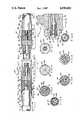
- FIG. 1shows a longitudinal, cross-sectional view of a coaxial connector according to the teachings of the present invention.
- FIG. 1Ashows a multi-connector arrangement including connectors according to FIG. 1 passing through a high pressure bulkhead.
- FIG. 2shows a cross-sectional view of the connector of FIG. 1 taken along section 2--2 thereof.
- FIG. 3shows a cross-sectional view of the connector of FIG. 1 taken along section 3--3 thereof.
- FIG. 4shows a cross-sectional view of the connector of FIG. 1 taken along section 4--4 thereof.
- FIG. 5shows a cross-sectional view of the connector of FIG. 1 taken along section 5--5 thereof.
- FIG. 6shows a cross-sectional view of the connector of FIG. 1 taken along section 6--6 thereof.
- FIG. 7shows a cross-sectional view of the connector of FIG. 1 taken along section 7--7 thereof.
- FIG. 8shows a cross-sectional view of the connector of FIG. 1 taken along section 8--8 thereof.
- FIG. 1there is shown a high frequency, hermetically sealed, coaxial cable connector assembly 10 according to the present invention.
- Assembly 10further comprises a plug 12 and a receptacle 14, each of which selectively provides a termination for an end of a coaxial cable 16.
- a typical coaxial cable 16has a round center conductor 18 which is covered by a cylindrical coaxial dielectric material 20. Over material 20 is disposed a second conductor 22 of metal braid, which braid is in turn covered by an outer cylindrical plastic jacket 24.
- Fixedly attached to such coaxial cable endsare a plug 12 and a receptacle 14 which when engaged together form a coaxial connector 10. Plugs 12 and receptacles 14 may be used singly or as part of multi-pin asemblies.
- Plug 12further comprises a first body 26 having concentrically positioned therein a first metal pin 28 which is held fixedly in place by a cylindrical fused glass insert 30.
- Glass insert 30has its outside diameter heat fused to the inside diameter of body 26 nearest to the coaxial cable and also has its inside diameter heat fused to pin 28.
- Insert 30is of thickness "t" which is made as thin as possible yet strong enough to hermetically seal and structurally support the desired axial open face pressure.
- the diameter "d" of pin 28 in contact with insert 30is undercut such that, in conjunction with the dielectric properties of the glass used, a constant impedance value matching that of the attached coaxial cable is maintained. Typically a value of 50 ohms is used for small diameter flexible coaxial cables.
- Body 26may have one or more access holes 26a formed therethrough at the cable end thereof if desired.
- the bodythus includes a fused glass insert that provides the pressure boundary for the center conductor to body inside diameter.
- the center conductoris generally sized for a 50 ohm impedance based on the dielectric constant of the glass for the frequency range considered.
- the connector designwill accept glass whose dielectric constant varies between 3.8 and 6.5.
- a first cylindrical plastic insulator 32 of teflon or the likeis press fit on the front end of pin 28, insulator 32 having an annular protrusion 32a which is force fit in body 26.
- a metal sleeve 34having a thin internal wall to retain solder, slideably connects the rear end of pin 28 to conductor 18 while a second plastic cylindrical insulator 36 encloses sleeve 34 and is itself housed within body 26, one face thereof being in contact with glass insert 30 and the opposite face contacting cable dielectric 20.
- a tapered body adapter 38is butted against one face of insulator 36 while within body 26 and tapers back a preselected distance beyond body 26 to provide support for braid 22 of cable 16.
- a circular groove 38amay be provided around adapter 38 which is then used in conjunction with holes 26a in body 26 to form a solder joint. Alternately, a 0.002-0.004 inch clearance may be provided between body 26 and adapter 38 for such a solder joint.
- the front end of pin 28has a tapered nose which extends beyond front insulator 32 but remains within the end plane of body 26.
- Sleeve 34is soldered to conductor 18 and braid 22 is soldered to body 26.
- the length "l" of body 26is selected so as to maintain pressure integrity.
- Receptacle 14is identical to plug 12 in most respects except for the female end portion which mates with male plug 12.
- Receptacle 14further comprises a second body 40 having concentrically positioned therein a second metal pin 42 which is held fixedly in place by cylindrical fused glass insert 30.
- a third cylindrical plastic insulator 44 of teflon or the likeis press fit on the front end of pin 42.
- Metal sleeve 34slideably connects the rear end of pin 42 to cable center conductor 18 while a fourth cylindrical insulator 46 encloses sleeve 34 and is itself housed within body 40, one face thereof being in contact with glass insert 30 and the opposite face contacting cable dielectric 20.
- a tapered body adapter 38is butted to one face of insulator 46 while within body 40 and tapers back a preselected distance beyond body 40 to support braid 22 of cable 16.
- the front end of pin 42has a hollow nose which extends beyond front insulator 44 but remains within the end plane of body 40.
- Sleeve 34is soldered to conductor 18 and braid 22 is soldered to body 40.
- FIG. 1Ashows a multi-pin pressure bulkhead assembly 50 which installs in a sleeve 52 which has been welded in a bulkhead 54 separating a high pressure space from a low pressure space.
- Assembly 50is sealably attached to sleeve 52 by means of ⁇ O ⁇ ring 56 which seats against a flange on body 57 of bulkhead assembly 50.
- a plurality of plugs 12are held in place in body 57 by means of insulator 58 which is sealed by ⁇ O ⁇ ring 60. The high pressure is thus distributed over the face of each plug 12 or receptacle 14 used in assembly 50.
- FIGS. 2 through 8show detail cross sections of plug 12 and receptacle 14 at selected points to aid in visualizing the structure of the assemblies.
- the connector componentsare sized and the assembly designed for butt joints between insulators to avoid air gaps which result in capacitive discontinuities (impendance mismatches) in the assembled condition in order to to achieve optimal electrical performance, especially at higher frequencies.
- the advantages of the present coaxial connectorare its adaptability to flexible coaxial cable, its small size, and its extended (RF) frequency coverage to 18.0 GHz.
- Current coaxial connectorsdo not exist that combine the unique features of minimum size, high frequency performance, open face pressure proof integrity, and usability for various diameter flexible coaxial cables.
- the inventioncombines all these features with standardized mating configurations of either SMA or TNC. Its small size and rugged construction permit it to be used as a component in marine outboard cable assemblies and hull penetrations.
- a hermetic, pressure proof coaxial connector for flexible cablesaccepts dielectric diameters to 0.187" while a larger connector with TNC mating configuration accepts up to 0.375". These connectors provide a low VSWR and RF attenuation to 18.0 GHz.
- the connector internal dimensionscan be changed to accept a lower glass dielectric constant, and/or a range of cable dielectric constants for varying materials, such as polyethylene, teflon, air-teflon, or spline type designs.
- the connector body outside diametercan be made pressure proof in a multipin assembly by various methods, such as adhesive bonding, laser welding, encapsulating or by using an "O-ring" to seal between the body and the surrounding material.
- a variety of metalscan be used for the body and center conductor as long as they are compatible with the fused glass. Maximum electrical conductivity is achieved by gold plating after the fusing operation.
Landscapes
- Coupling Device And Connection With Printed Circuit (AREA)
Abstract
Description
The invention described herein may be manufactured and used by or for the Government of the United States of America for governmental purposes without the payment of any royalties thereon or therefor.
(1) Field of the Invention
The present invention relates to coaxial connectors and more particularly to a high frequency, hermetically sealed coaxial connector for use with small diameter flexible cables.
(2) Description of the Prior Art
Currently, there are no coaxial connectors available that are pressure proof to the center conductor, useable with flexible coaxial cables having 0.187 inch or 0.375 inch dielectric diameters, of small size, and provide (RF) electrical performance for frequencies up to 18.0 GHz. Miniature, glass fused SMA connectors exist that accept small diameter (0.141 inch) semirigid coaxial cable with a solid jacketed outer conductor, but can not be used with flexible cable. D. G. OBrien Inc., of Seabrook, NH, makes a coaxial plug-receptacle connector assembly for RG-58 size flexible coaxial cable, but frequency coverage is only up to 2GHz and connector size is prohibitively large. High frequency coaxial connectors are not available that accept small diameter flexible coaxial cables and that offer pressure integrity to the center conductor.
Accordingly, it is a general purpose and object of the present invention to provide a connector for small diameter, flexible, coaxial cable. It is a further object that the connector be hermetically sealed. Another object is that the connector accommodate frequencies up to 18.0 GHz. A still further object is that the connector provide pressure integrity to the center conductor.
These objects are accomplished with the present invention by providing a hermetically sealed, pressure-proof, coaxial connector for small diameter flexible coaxial cables. A receptacle configuration and a matching plug configuration engageably interconnect to form a connector. Connector size (diameter) may be varied to conform to industry standard coaxial cable sizes and connector mating configurations. A smaller connector with SMA mating configuration would accept dielectric diameters to up 0.187" while a larger connector with TNC mating configuration would accept up to 0.375" diameter. Such connectors provide a low VSWR and RF attenuation to 18.0 GHz.
A more complete understanding of the invention and many of the attendant advantages thereto will be readily appreciated as the same becomes better understood by reference to the following detailed description when considered in conjunction with the accompanying drawings wherein:
FIG. 1 shows a longitudinal, cross-sectional view of a coaxial connector according to the teachings of the present invention.
FIG. 1A shows a multi-connector arrangement including connectors according to FIG. 1 passing through a high pressure bulkhead.
FIG. 2 shows a cross-sectional view of the connector of FIG. 1 taken alongsection 2--2 thereof.
FIG. 3 shows a cross-sectional view of the connector of FIG. 1 taken alongsection 3--3 thereof.
FIG. 4 shows a cross-sectional view of the connector of FIG. 1 taken along section 4--4 thereof.
FIG. 5 shows a cross-sectional view of the connector of FIG. 1 taken alongsection 5--5 thereof.
FIG. 6 shows a cross-sectional view of the connector of FIG. 1 taken along section 6--6 thereof.
FIG. 7 shows a cross-sectional view of the connector of FIG. 1 taken along section 7--7 thereof.
FIG. 8 shows a cross-sectional view of the connector of FIG. 1 taken along section 8--8 thereof.
Referring now to FIG. 1 there is shown a high frequency, hermetically sealed, coaxialcable connector assembly 10 according to the present invention.Assembly 10 further comprises aplug 12 and a receptacle 14, each of which selectively provides a termination for an end of acoaxial cable 16. A typicalcoaxial cable 16 has around center conductor 18 which is covered by a cylindrical coaxialdielectric material 20. Overmaterial 20 is disposed asecond conductor 22 of metal braid, which braid is in turn covered by an outer cylindricalplastic jacket 24. Fixedly attached to such coaxial cable ends are aplug 12 and a receptacle 14 which when engaged together form acoaxial connector 10.Plugs 12 and receptacles 14 may be used singly or as part of multi-pin asemblies.
A first cylindricalplastic insulator 32 of teflon or the like is press fit on the front end ofpin 28,insulator 32 having anannular protrusion 32a which is force fit inbody 26. Ametal sleeve 34, having a thin internal wall to retain solder, slideably connects the rear end ofpin 28 toconductor 18 while a second plasticcylindrical insulator 36 enclosessleeve 34 and is itself housed withinbody 26, one face thereof being in contact withglass insert 30 and the opposite face contacting cable dielectric 20. Atapered body adapter 38 is butted against one face ofinsulator 36 while withinbody 26 and tapers back a preselected distance beyondbody 26 to provide support forbraid 22 ofcable 16. Acircular groove 38a may be provided aroundadapter 38 which is then used in conjunction withholes 26a inbody 26 to form a solder joint. Alternately, a 0.002-0.004 inch clearance may be provided betweenbody 26 andadapter 38 for such a solder joint. The front end ofpin 28 has a tapered nose which extends beyondfront insulator 32 but remains within the end plane ofbody 26. Sleeve 34 is soldered toconductor 18 andbraid 22 is soldered tobody 26. The length "l" ofbody 26 is selected so as to maintain pressure integrity.
Receptacle 14, is identical toplug 12 in most respects except for the female end portion which mates withmale plug 12. Receptacle 14 further comprises asecond body 40 having concentrically positioned therein asecond metal pin 42 which is held fixedly in place by cylindricalfused glass insert 30. A third cylindricalplastic insulator 44 of teflon or the like is press fit on the front end ofpin 42.Metal sleeve 34 slideably connects the rear end ofpin 42 tocable center conductor 18 while a fourth cylindrical insulator 46 enclosessleeve 34 and is itself housed withinbody 40, one face thereof being in contact withglass insert 30 and the opposite face contacting cable dielectric 20. Atapered body adapter 38 is butted to one face of insulator 46 while withinbody 40 and tapers back a preselected distance beyondbody 40 to supportbraid 22 ofcable 16. The front end ofpin 42 has a hollow nose which extends beyondfront insulator 44 but remains within the end plane ofbody 40. Sleeve 34 is soldered toconductor 18 andbraid 22 is soldered tobody 40.
FIG. 1A shows a multi-pinpressure bulkhead assembly 50 which installs in a sleeve 52 which has been welded in abulkhead 54 separating a high pressure space from a low pressure space.Assembly 50 is sealably attached to sleeve 52 by means of `O` ring 56 which seats against a flange on body 57 ofbulkhead assembly 50. A plurality ofplugs 12 are held in place in body 57 by means ofinsulator 58 which is sealed by `O`ring 60. The high pressure is thus distributed over the face of each plug 12 or receptacle 14 used inassembly 50.
FIGS. 2 through 8 show detail cross sections ofplug 12 and receptacle 14 at selected points to aid in visualizing the structure of the assemblies.
Since the cable and connector preparation are similar for each size connector and connector sex (plug or receptacle) the assembly procedure steps are described for attaching aplug 12 to a coaxial cable.
______________________________________ Step 1Trim cable jacket 24 back a preselected length. 2 Comb outbraid 22 and fold away. 3 Cutcable dielectric 20 away a preselected length. 4Tin center conductor 18. 5Solder adapter sleeve 34 tocenter conductor 18. 6Slide body adapter 38 overcable dielectric 20 until flush with the cut end ofcable dielectric 20. 7Slide teflon insulator 36 overadapter sleeve 34. 8 Slide completed assembly into rear end ofconnector body 26 untilinsulator 36 has bottomed againstinsert 30. 9 While holding the assembly in the bottomed position,solder body adapter 38 toconnector body 26. 10Fold braid 22 forward overbody adapter 38 and cut off excess braid that touchesconnector body 26. 11Solder cable braid 22 tobody adapter 38. ______________________________________
The connector components are sized and the assembly designed for butt joints between insulators to avoid air gaps which result in capacitive discontinuities (impendance mismatches) in the assembled condition in order to to achieve optimal electrical performance, especially at higher frequencies.
The advantages of the present coaxial connector are its adaptability to flexible coaxial cable, its small size, and its extended (RF) frequency coverage to 18.0 GHz. Current coaxial connectors do not exist that combine the unique features of minimum size, high frequency performance, open face pressure proof integrity, and usability for various diameter flexible coaxial cables. The invention combines all these features with standardized mating configurations of either SMA or TNC. Its small size and rugged construction permit it to be used as a component in marine outboard cable assemblies and hull penetrations.
What has thus been described is a hermetic, pressure proof coaxial connector for flexible cables. A small connector with SMA mating configuration accepts dielectric diameters to 0.187" while a larger connector with TNC mating configuration accepts up to 0.375". These connectors provide a low VSWR and RF attenuation to 18.0 GHz.
Obviously many modifications and variations of the present invention may become apparent in light of the above teachings. For example: The connector internal dimensions can be changed to accept a lower glass dielectric constant, and/or a range of cable dielectric constants for varying materials, such as polyethylene, teflon, air-teflon, or spline type designs. The connector body outside diameter can be made pressure proof in a multipin assembly by various methods, such as adhesive bonding, laser welding, encapsulating or by using an "O-ring" to seal between the body and the surrounding material. A variety of metals can be used for the body and center conductor as long as they are compatible with the fused glass. Maximum electrical conductivity is achieved by gold plating after the fusing operation.
In light of the above, it is therefore understood that within the scope of the appended claims, the invention may be practiced otherwise than as specifically described.
Claims (2)
1. A coaxial connector for shieldably joining together one end each of a first and second flexible coaxial cable, each said cable having identical impedance and a diameter no greater than 0.375 of an inch, comprising:
plug means, fixedly attached to said first coaxial cable, for providing a male ended cable termination having an impedance corresponding to said first coaxial cable, said plug means further comprising a first hollow, cylindrical body having a cable end and a connector end and first and second coaxial internal bores of different diameter, such that said first bore of smaller diameter extends a preselected depth into said first body from said connector end and said second bore of larger diameter extends a preselected depth into said first body from said cable end, a first internal body shoulder being formed where said first and second bores meet, a first cylindrical metal pin, concentrically positioned within said first body, said first pin having a length substantially greater than the diameter thereof and an undercut of preselected length formed thereupon at a preselected location along the length thereof thereby forming first and second pin shoulders, and further having first and second tapered ends, said first tapered end aligning with said first body connector end and said first pin shoulder aligning with said first body shoulder, for providing an electrically conducting path therethrough, a first fused glass cylindrical insert, having a preselected thickness, a cable end surface, a connector end surface and a dielectric constant, said first insert being heat fused to said second bore, said first body shoulder and said first pin undercut, for providing axial open-face pressure strength and hermetically sealing said plug means, a first cylindrical plastic insulator, press fit on said connector end of said pin and contacting the periphery of said first bore and the connector end surface of said first insert, a first metal sleeve, slideably engaing said second tapered end of said first metal pin and soldered to the central conductor of said coaxial connector, for providing electrical conduction therebetween, a second cylindrical plastic insulator, positioned within said first body over said first sleeve and contacting said second bore, contacting the cable end surface of said first insert and contacting the cable dielectric, for providing an impedance matching that of said cable, and a first tapered metal adapter, inserted within and fixedly attached to said second bore and being soldered to the outer metal braid of said coaxial cable, for providing support for said braid and electrical conductivity; and
receptacle means, fixedly attached to said second coaxial cable, for providing a female ended cable termination having an impedance corresponding to said second coaxial cable;
said male and female ends being slideably engagable with one another such that when coupled together a coaxial, first cable-to-second cable joint is formed having a continuous impedance corresponding to that of said first and second coaxial cables.
2. A connector according to claim 1 wherein said receptacle means further comprises:
a second hollow, cylindrical body having a cable end and a connector end and third and fourth coaxial internal bores of different diameter, such that said third bore of smaller diameter extends a preselected depth into said second body from said connector end and said fourth bore of larger diameter extends a preselected depth into said second body from said cable end, a second internal body shoulder being formed where said third and fourth bores meet;
a second cylindrical metal pin, concentrically positioned within said second body, said second pin having a length substantially greater than the diameter thereof and an undercut of preselected length formed thereupon at a preselected location along the length thereof thereby forming third and fourth pin shoulders, and further having a third tapered end and a hollow end, said hollow end being recessed within said first body connector end and said third pin shoulder aligning with said second body shoulder, for providing an electrically conducting path therethrough;
a second fused glass cylindrical insert, having a preselected thickness, a cable end surface, a connector end surface and a dielectric constant, said second insert being heat fused to said fourth bore, said second body shoulder and said second pin undercut, for providing axial open-face pressure strength and hermetically sealing said receptacle means;
a third cylindrical plastic insulator, press fit on said connector end of said second pin and contacting the periphery of said third bore and the connector end surface of said second insert;
a second metal sleeve, slideably engaging said third tapered end of said second metal pin and soldered to the central conductor of said coaxial connector, for providing electrical conduction therebetween;
a fourth cylindrical plastic insulator, positioned within said second body over said second sleeve and contacting said fourth bore, contacting the cable end surface of said second insert and contacting the cable dielectric, for providing an impedance matching that of said cable; and
a second tapered metal adapter, inserted within and fixedly attached to said fourth bore and being soldered to the outer metal braid of said coaxial cable, for providing support for said braid and electrical conductivity.
Priority Applications (1)
| Application Number | Priority Date | Filing Date | Title |
|---|---|---|---|
| US06/881,366US4690482A (en) | 1986-07-07 | 1986-07-07 | High frequency, hermetic, coaxial connector for flexible cable |
Applications Claiming Priority (1)
| Application Number | Priority Date | Filing Date | Title |
|---|---|---|---|
| US06/881,366US4690482A (en) | 1986-07-07 | 1986-07-07 | High frequency, hermetic, coaxial connector for flexible cable |
Publications (1)
| Publication Number | Publication Date |
|---|---|
| US4690482Atrue US4690482A (en) | 1987-09-01 |
Family
ID=25378338
Family Applications (1)
| Application Number | Title | Priority Date | Filing Date |
|---|---|---|---|
| US06/881,366Expired - Fee RelatedUS4690482A (en) | 1986-07-07 | 1986-07-07 | High frequency, hermetic, coaxial connector for flexible cable |
Country Status (1)
| Country | Link |
|---|---|
| US (1) | US4690482A (en) |
Cited By (62)
| Publication number | Priority date | Publication date | Assignee | Title |
|---|---|---|---|---|
| US4941846A (en)* | 1989-05-31 | 1990-07-17 | Adams-Russell Electronic Company, Inc. | Quick connect/disconnect microwave connector |
| US5823790A (en)* | 1996-07-29 | 1998-10-20 | Lucent Technologies Inc. | Connector for attaching a cable to a printed circuit board |
| US5879188A (en)* | 1996-10-11 | 1999-03-09 | Elco U.S.A. Inc. | Coaxial connector |
| US5998736A (en)* | 1998-01-20 | 1999-12-07 | Relight America, Inc. | High voltage wiring system for neon lights |
| US6231357B1 (en) | 1998-01-20 | 2001-05-15 | Relight America, Inc. | Waterproof high voltage connector |
| US6454601B1 (en) | 2001-06-27 | 2002-09-24 | Andrew Corporation | Connector for coaxial cables |
| US20030120327A1 (en)* | 2001-12-20 | 2003-06-26 | Mark Tobritzhofer | Medical lead adaptor assembly with retainer |
| US20040178868A1 (en)* | 2003-03-14 | 2004-09-16 | Whitener Michael B. | Adjustable coaxial support |
| US20050176292A1 (en)* | 2002-04-01 | 2005-08-11 | Hai-Young Lee | Coaxial connector and connection structure including the same |
| US20050227526A1 (en)* | 2004-04-08 | 2005-10-13 | Thermo/Probes Inc. | Thermocouples and resistance temperature detectors oil-wicking seal fitting |
| US20060208644A1 (en)* | 2005-03-17 | 2006-09-21 | Farzad Kialashaki | Robust RF interface in TWT |
| US20060258225A1 (en)* | 2005-05-10 | 2006-11-16 | Lih Yeu Seng Industries Co., Ltd. | Adapter for high frequency signal transmission |
| US20110252642A1 (en)* | 2009-01-21 | 2011-10-20 | John Mezzalingua Associates, Inc. | Coaxial cable connector insulator and method of use thereof |
| US8313353B2 (en) | 2009-05-22 | 2012-11-20 | John Mezzalingua Associates, Inc. | Coaxial cable connector having electrical continuity member |
| US8323053B2 (en) | 2010-10-18 | 2012-12-04 | John Mezzalingua Associates, Inc. | Connector having a constant contact nut |
| US8337229B2 (en) | 2010-11-11 | 2012-12-25 | John Mezzalingua Associates, Inc. | Connector having a nut-body continuity element and method of use thereof |
| US8366481B2 (en) | 2011-03-30 | 2013-02-05 | John Mezzalingua Associates, Inc. | Continuity maintaining biasing member |
| US8382517B2 (en) | 2010-10-18 | 2013-02-26 | John Mezzalingua Associates, Inc. | Dielectric sealing member and method of use thereof |
| US8398421B2 (en) | 2011-02-01 | 2013-03-19 | John Mezzalingua Associates, Inc. | Connector having a dielectric seal and method of use thereof |
| US8414322B2 (en) | 2010-12-14 | 2013-04-09 | Ppc Broadband, Inc. | Push-on CATV port terminator |
| US8444445B2 (en) | 2009-05-22 | 2013-05-21 | Ppc Broadband, Inc. | Coaxial cable connector having electrical continuity member |
| US8465322B2 (en) | 2011-03-25 | 2013-06-18 | Ppc Broadband, Inc. | Coaxial cable connector |
| US8469739B2 (en) | 2011-02-08 | 2013-06-25 | Belden Inc. | Cable connector with biasing element |
| US8506325B2 (en) | 2008-09-30 | 2013-08-13 | Belden Inc. | Cable connector having a biasing element |
| US8573996B2 (en) | 2009-05-22 | 2013-11-05 | Ppc Broadband, Inc. | Coaxial cable connector having electrical continuity member |
| US8591244B2 (en) | 2011-07-08 | 2013-11-26 | Ppc Broadband, Inc. | Cable connector |
| US8888526B2 (en) | 2010-08-10 | 2014-11-18 | Corning Gilbert, Inc. | Coaxial cable connector with radio frequency interference and grounding shield |
| US9017101B2 (en) | 2011-03-30 | 2015-04-28 | Ppc Broadband, Inc. | Continuity maintaining biasing member |
| US9048599B2 (en) | 2013-10-28 | 2015-06-02 | Corning Gilbert Inc. | Coaxial cable connector having a gripping member with a notch and disposed inside a shell |
| US9071019B2 (en) | 2010-10-27 | 2015-06-30 | Corning Gilbert, Inc. | Push-on cable connector with a coupler and retention and release mechanism |
| US9136654B2 (en) | 2012-01-05 | 2015-09-15 | Corning Gilbert, Inc. | Quick mount connector for a coaxial cable |
| US9147963B2 (en) | 2012-11-29 | 2015-09-29 | Corning Gilbert Inc. | Hardline coaxial connector with a locking ferrule |
| US9147955B2 (en) | 2011-11-02 | 2015-09-29 | Ppc Broadband, Inc. | Continuity providing port |
| US9153911B2 (en) | 2013-02-19 | 2015-10-06 | Corning Gilbert Inc. | Coaxial cable continuity connector |
| US9166348B2 (en) | 2010-04-13 | 2015-10-20 | Corning Gilbert Inc. | Coaxial connector with inhibited ingress and improved grounding |
| US9172154B2 (en) | 2013-03-15 | 2015-10-27 | Corning Gilbert Inc. | Coaxial cable connector with integral RFI protection |
| US9190744B2 (en) | 2011-09-14 | 2015-11-17 | Corning Optical Communications Rf Llc | Coaxial cable connector with radio frequency interference and grounding shield |
| US9203167B2 (en) | 2011-05-26 | 2015-12-01 | Ppc Broadband, Inc. | Coaxial cable connector with conductive seal |
| US9287659B2 (en) | 2012-10-16 | 2016-03-15 | Corning Optical Communications Rf Llc | Coaxial cable connector with integral RFI protection |
| US9312611B2 (en) | 2004-11-24 | 2016-04-12 | Ppc Broadband, Inc. | Connector having a conductively coated member and method of use thereof |
| US9407016B2 (en) | 2012-02-22 | 2016-08-02 | Corning Optical Communications Rf Llc | Coaxial cable connector with integral continuity contacting portion |
| JP2016195125A (en)* | 2013-03-13 | 2016-11-17 | インターナショナル・ビジネス・マシーンズ・コーポレーションInternational Business Machines Corporation | Microwave connector and connector |
| US9525220B1 (en) | 2015-11-25 | 2016-12-20 | Corning Optical Communications LLC | Coaxial cable connector |
| US9548572B2 (en) | 2014-11-03 | 2017-01-17 | Corning Optical Communications LLC | Coaxial cable connector having a coupler and a post with a contacting portion and a shoulder |
| US9548557B2 (en) | 2013-06-26 | 2017-01-17 | Corning Optical Communications LLC | Connector assemblies and methods of manufacture |
| US9570845B2 (en) | 2009-05-22 | 2017-02-14 | Ppc Broadband, Inc. | Connector having a continuity member operable in a radial direction |
| US20170054247A1 (en)* | 2014-04-30 | 2017-02-23 | Eaton Corporation | High pressure sealed electrical connector |
| US9590287B2 (en) | 2015-02-20 | 2017-03-07 | Corning Optical Communications Rf Llc | Surge protected coaxial termination |
| US9711917B2 (en) | 2011-05-26 | 2017-07-18 | Ppc Broadband, Inc. | Band spring continuity member for coaxial cable connector |
| US9762008B2 (en) | 2013-05-20 | 2017-09-12 | Corning Optical Communications Rf Llc | Coaxial cable connector with integral RFI protection |
| US9768543B2 (en) | 2015-12-17 | 2017-09-19 | Sri Hermetics, Llc | Cable end termination including cable dielectric layer hermetic seal and related methods |
| US9859631B2 (en) | 2011-09-15 | 2018-01-02 | Corning Optical Communications Rf Llc | Coaxial cable connector with integral radio frequency interference and grounding shield |
| US10033122B2 (en) | 2015-02-20 | 2018-07-24 | Corning Optical Communications Rf Llc | Cable or conduit connector with jacket retention feature |
| US10096955B1 (en) | 2017-10-02 | 2018-10-09 | The United States Of America As Represented By The Secretary Of The Navy | High voltage radio frequency coaxial cable connector |
| US10211547B2 (en) | 2015-09-03 | 2019-02-19 | Corning Optical Communications Rf Llc | Coaxial cable connector |
| US10290958B2 (en) | 2013-04-29 | 2019-05-14 | Corning Optical Communications Rf Llc | Coaxial cable connector with integral RFI protection and biasing ring |
| US10439323B1 (en) | 2017-10-02 | 2019-10-08 | The United States Of America, As Represented By The Secretary Of The Navy | High voltage RF connector for coaxial-to-stripline transition |
| WO2019212526A1 (en)* | 2018-04-30 | 2019-11-07 | Hewlett-Packard Development Company, L.P. | Retention devices |
| US10756455B2 (en) | 2005-01-25 | 2020-08-25 | Corning Optical Communications Rf Llc | Electrical connector with grounding member |
| US20220085539A1 (en)* | 2020-09-14 | 2022-03-17 | Molex, Llc | Electrical connector |
| CN114323444A (en)* | 2021-12-07 | 2022-04-12 | 北京无线电计量测试研究所 | High-temperature-resistant sealed cavity testing device and configuration method |
| US12034264B2 (en) | 2021-03-31 | 2024-07-09 | Corning Optical Communications Rf Llc | Coaxial cable connector assemblies with outer conductor engagement features and methods for using the same |
Citations (6)
| Publication number | Priority date | Publication date | Assignee | Title |
|---|---|---|---|---|
| US3721943A (en)* | 1969-01-21 | 1973-03-20 | Deutsch Co Elec Comp | Electrical connecting device |
| US4231003A (en)* | 1977-12-21 | 1980-10-28 | The Director-General Of National Laboratory For High Energy Physics | Shield-type coaxial vacuum feedthrough |
| US4420210A (en)* | 1981-09-17 | 1983-12-13 | The Bendix Corporation | Hermetic through bulkhead electrical connector |
| US4545637A (en)* | 1982-11-24 | 1985-10-08 | Huber & Suhner Ag | Plug connector and method for connecting same |
| US4556271A (en)* | 1983-10-14 | 1985-12-03 | M/A-Com Omni Spectra, Inc. | Hermetically sealed connector |
| US4593758A (en)* | 1981-11-16 | 1986-06-10 | Kyle James C | Hermetically sealed insulating assembly |
- 1986
- 1986-07-07USUS06/881,366patent/US4690482A/ennot_activeExpired - Fee Related
Patent Citations (6)
| Publication number | Priority date | Publication date | Assignee | Title |
|---|---|---|---|---|
| US3721943A (en)* | 1969-01-21 | 1973-03-20 | Deutsch Co Elec Comp | Electrical connecting device |
| US4231003A (en)* | 1977-12-21 | 1980-10-28 | The Director-General Of National Laboratory For High Energy Physics | Shield-type coaxial vacuum feedthrough |
| US4420210A (en)* | 1981-09-17 | 1983-12-13 | The Bendix Corporation | Hermetic through bulkhead electrical connector |
| US4593758A (en)* | 1981-11-16 | 1986-06-10 | Kyle James C | Hermetically sealed insulating assembly |
| US4545637A (en)* | 1982-11-24 | 1985-10-08 | Huber & Suhner Ag | Plug connector and method for connecting same |
| US4556271A (en)* | 1983-10-14 | 1985-12-03 | M/A-Com Omni Spectra, Inc. | Hermetically sealed connector |
Cited By (122)
| Publication number | Priority date | Publication date | Assignee | Title |
|---|---|---|---|---|
| US4941846A (en)* | 1989-05-31 | 1990-07-17 | Adams-Russell Electronic Company, Inc. | Quick connect/disconnect microwave connector |
| US5823790A (en)* | 1996-07-29 | 1998-10-20 | Lucent Technologies Inc. | Connector for attaching a cable to a printed circuit board |
| US5879188A (en)* | 1996-10-11 | 1999-03-09 | Elco U.S.A. Inc. | Coaxial connector |
| US5998736A (en)* | 1998-01-20 | 1999-12-07 | Relight America, Inc. | High voltage wiring system for neon lights |
| US6231357B1 (en) | 1998-01-20 | 2001-05-15 | Relight America, Inc. | Waterproof high voltage connector |
| US6454601B1 (en) | 2001-06-27 | 2002-09-24 | Andrew Corporation | Connector for coaxial cables |
| US20030120327A1 (en)* | 2001-12-20 | 2003-06-26 | Mark Tobritzhofer | Medical lead adaptor assembly with retainer |
| US20050176292A1 (en)* | 2002-04-01 | 2005-08-11 | Hai-Young Lee | Coaxial connector and connection structure including the same |
| US7262672B2 (en)* | 2002-04-01 | 2007-08-28 | Gigalane Co., Ltd. | Coaxial connector and connection structure including the same |
| US20040178868A1 (en)* | 2003-03-14 | 2004-09-16 | Whitener Michael B. | Adjustable coaxial support |
| US6870448B2 (en) | 2003-03-14 | 2005-03-22 | Agilent Technologies, Inc. | Adjustable coaxial support |
| US20050227526A1 (en)* | 2004-04-08 | 2005-10-13 | Thermo/Probes Inc. | Thermocouples and resistance temperature detectors oil-wicking seal fitting |
| US7422459B2 (en)* | 2004-04-08 | 2008-09-09 | Hopper Troy K | Thermocouples and resistance temperature detectors oil-wicking seal fitting |
| US10038284B2 (en) | 2004-11-24 | 2018-07-31 | Ppc Broadband, Inc. | Connector having a grounding member |
| US10446983B2 (en) | 2004-11-24 | 2019-10-15 | Ppc Broadband, Inc. | Connector having a grounding member |
| US9312611B2 (en) | 2004-11-24 | 2016-04-12 | Ppc Broadband, Inc. | Connector having a conductively coated member and method of use thereof |
| US10965063B2 (en) | 2004-11-24 | 2021-03-30 | Ppc Broadband, Inc. | Connector having a grounding member |
| US11984687B2 (en) | 2004-11-24 | 2024-05-14 | Ppc Broadband, Inc. | Connector having a grounding member |
| US12009619B2 (en) | 2004-11-24 | 2024-06-11 | Ppc Broadband, Inc. | Connector having a connector body conductive member |
| US10756455B2 (en) | 2005-01-25 | 2020-08-25 | Corning Optical Communications Rf Llc | Electrical connector with grounding member |
| US7230384B2 (en)* | 2005-03-17 | 2007-06-12 | Whittaker Corporation | Robust RF interface in a TWT |
| US20060208644A1 (en)* | 2005-03-17 | 2006-09-21 | Farzad Kialashaki | Robust RF interface in TWT |
| US7217160B2 (en)* | 2005-05-10 | 2007-05-15 | Lih Yeu Seng Industries Co., Ltd. | Adapter for high frequency signal transmission |
| US20060258225A1 (en)* | 2005-05-10 | 2006-11-16 | Lih Yeu Seng Industries Co., Ltd. | Adapter for high frequency signal transmission |
| US8506325B2 (en) | 2008-09-30 | 2013-08-13 | Belden Inc. | Cable connector having a biasing element |
| US20110252642A1 (en)* | 2009-01-21 | 2011-10-20 | John Mezzalingua Associates, Inc. | Coaxial cable connector insulator and method of use thereof |
| US10931068B2 (en) | 2009-05-22 | 2021-02-23 | Ppc Broadband, Inc. | Connector having a grounding member operable in a radial direction |
| US9496661B2 (en) | 2009-05-22 | 2016-11-15 | Ppc Broadband, Inc. | Coaxial cable connector having electrical continuity member |
| US9660398B2 (en) | 2009-05-22 | 2017-05-23 | Ppc Broadband, Inc. | Coaxial cable connector having electrical continuity member |
| US8313353B2 (en) | 2009-05-22 | 2012-11-20 | John Mezzalingua Associates, Inc. | Coaxial cable connector having electrical continuity member |
| US9570845B2 (en) | 2009-05-22 | 2017-02-14 | Ppc Broadband, Inc. | Connector having a continuity member operable in a radial direction |
| US12244108B2 (en) | 2009-05-22 | 2025-03-04 | Ppc Broadband, Inc. | Ground portion for maintaining a ground path in a coaxial cable connector |
| US8323060B2 (en) | 2009-05-22 | 2012-12-04 | John Mezzalingua Associates, Inc. | Coaxial cable connector having electrical continuity member |
| US8647136B2 (en) | 2009-05-22 | 2014-02-11 | Ppc Broadband, Inc. | Coaxial cable connector having electrical continuity member |
| US8444445B2 (en) | 2009-05-22 | 2013-05-21 | Ppc Broadband, Inc. | Coaxial cable connector having electrical continuity member |
| US9419389B2 (en) | 2009-05-22 | 2016-08-16 | Ppc Broadband, Inc. | Coaxial cable connector having electrical continuity member |
| US10862251B2 (en) | 2009-05-22 | 2020-12-08 | Ppc Broadband, Inc. | Coaxial cable connector having an electrical grounding portion |
| US8562366B2 (en) | 2009-05-22 | 2013-10-22 | Ppc Broadband, Inc. | Coaxial cable connector having electrical continuity member |
| US8573996B2 (en) | 2009-05-22 | 2013-11-05 | Ppc Broadband, Inc. | Coaxial cable connector having electrical continuity member |
| US8801448B2 (en) | 2009-05-22 | 2014-08-12 | Ppc Broadband, Inc. | Coaxial cable connector having electrical continuity structure |
| US8597041B2 (en) | 2009-05-22 | 2013-12-03 | Ppc Broadband, Inc. | Coaxial cable connector having electrical continuity member |
| US10312629B2 (en) | 2010-04-13 | 2019-06-04 | Corning Optical Communications Rf Llc | Coaxial connector with inhibited ingress and improved grounding |
| US9166348B2 (en) | 2010-04-13 | 2015-10-20 | Corning Gilbert Inc. | Coaxial connector with inhibited ingress and improved grounding |
| US9905959B2 (en) | 2010-04-13 | 2018-02-27 | Corning Optical Communication RF LLC | Coaxial connector with inhibited ingress and improved grounding |
| US8888526B2 (en) | 2010-08-10 | 2014-11-18 | Corning Gilbert, Inc. | Coaxial cable connector with radio frequency interference and grounding shield |
| US8323053B2 (en) | 2010-10-18 | 2012-12-04 | John Mezzalingua Associates, Inc. | Connector having a constant contact nut |
| US8382517B2 (en) | 2010-10-18 | 2013-02-26 | John Mezzalingua Associates, Inc. | Dielectric sealing member and method of use thereof |
| US9071019B2 (en) | 2010-10-27 | 2015-06-30 | Corning Gilbert, Inc. | Push-on cable connector with a coupler and retention and release mechanism |
| US8858251B2 (en) | 2010-11-11 | 2014-10-14 | Ppc Broadband, Inc. | Connector having a coupler-body continuity member |
| US8920192B2 (en) | 2010-11-11 | 2014-12-30 | Ppc Broadband, Inc. | Connector having a coupler-body continuity member |
| US8337229B2 (en) | 2010-11-11 | 2012-12-25 | John Mezzalingua Associates, Inc. | Connector having a nut-body continuity element and method of use thereof |
| US8920182B2 (en) | 2010-11-11 | 2014-12-30 | Ppc Broadband, Inc. | Connector having a coupler-body continuity member |
| US8550835B2 (en) | 2010-11-11 | 2013-10-08 | Ppc Broadband, Inc. | Connector having a nut-body continuity element and method of use thereof |
| US8529279B2 (en) | 2010-11-11 | 2013-09-10 | Ppc Broadband, Inc. | Connector having a nut-body continuity element and method of use thereof |
| US8915754B2 (en) | 2010-11-11 | 2014-12-23 | Ppc Broadband, Inc. | Connector having a coupler-body continuity member |
| US10686264B2 (en) | 2010-11-11 | 2020-06-16 | Ppc Broadband, Inc. | Coaxial cable connector having a grounding bridge portion |
| US8414322B2 (en) | 2010-12-14 | 2013-04-09 | Ppc Broadband, Inc. | Push-on CATV port terminator |
| WO2012106402A3 (en)* | 2011-02-01 | 2014-04-17 | John Mezzalingua Associates, Inc. | Connector having a dielectric seal and method of use thereof |
| US8398421B2 (en) | 2011-02-01 | 2013-03-19 | John Mezzalingua Associates, Inc. | Connector having a dielectric seal and method of use thereof |
| US8469739B2 (en) | 2011-02-08 | 2013-06-25 | Belden Inc. | Cable connector with biasing element |
| US9153917B2 (en) | 2011-03-25 | 2015-10-06 | Ppc Broadband, Inc. | Coaxial cable connector |
| US8465322B2 (en) | 2011-03-25 | 2013-06-18 | Ppc Broadband, Inc. | Coaxial cable connector |
| US11811184B2 (en) | 2011-03-30 | 2023-11-07 | Ppc Broadband, Inc. | Connector producing a biasing force |
| US9595776B2 (en) | 2011-03-30 | 2017-03-14 | Ppc Broadband, Inc. | Connector producing a biasing force |
| US9660360B2 (en) | 2011-03-30 | 2017-05-23 | Ppc Broadband, Inc. | Connector producing a biasing force |
| US8366481B2 (en) | 2011-03-30 | 2013-02-05 | John Mezzalingua Associates, Inc. | Continuity maintaining biasing member |
| US8485845B2 (en) | 2011-03-30 | 2013-07-16 | Ppc Broadband, Inc. | Continuity maintaining biasing member |
| US9017101B2 (en) | 2011-03-30 | 2015-04-28 | Ppc Broadband, Inc. | Continuity maintaining biasing member |
| US9608345B2 (en) | 2011-03-30 | 2017-03-28 | Ppc Broadband, Inc. | Continuity maintaining biasing member |
| US10559898B2 (en) | 2011-03-30 | 2020-02-11 | Ppc Broadband, Inc. | Connector producing a biasing force |
| US8480431B2 (en) | 2011-03-30 | 2013-07-09 | Ppc Broadband, Inc. | Continuity maintaining biasing member |
| US8480430B2 (en) | 2011-03-30 | 2013-07-09 | Ppc Broadband, Inc. | Continuity maintaining biasing member |
| US8475205B2 (en) | 2011-03-30 | 2013-07-02 | Ppc Broadband, Inc. | Continuity maintaining biasing member |
| US10186790B2 (en) | 2011-03-30 | 2019-01-22 | Ppc Broadband, Inc. | Connector producing a biasing force |
| US8469740B2 (en) | 2011-03-30 | 2013-06-25 | Ppc Broadband, Inc. | Continuity maintaining biasing member |
| US11283226B2 (en) | 2011-05-26 | 2022-03-22 | Ppc Broadband, Inc. | Grounding member for coaxial cable connector |
| US10707629B2 (en) | 2011-05-26 | 2020-07-07 | Ppc Broadband, Inc. | Grounding member for coaxial cable connector |
| US9203167B2 (en) | 2011-05-26 | 2015-12-01 | Ppc Broadband, Inc. | Coaxial cable connector with conductive seal |
| US9711917B2 (en) | 2011-05-26 | 2017-07-18 | Ppc Broadband, Inc. | Band spring continuity member for coaxial cable connector |
| US8591244B2 (en) | 2011-07-08 | 2013-11-26 | Ppc Broadband, Inc. | Cable connector |
| US9190744B2 (en) | 2011-09-14 | 2015-11-17 | Corning Optical Communications Rf Llc | Coaxial cable connector with radio frequency interference and grounding shield |
| US9859631B2 (en) | 2011-09-15 | 2018-01-02 | Corning Optical Communications Rf Llc | Coaxial cable connector with integral radio frequency interference and grounding shield |
| US9147955B2 (en) | 2011-11-02 | 2015-09-29 | Ppc Broadband, Inc. | Continuity providing port |
| US10700475B2 (en) | 2011-11-02 | 2020-06-30 | Ppc Broadband, Inc. | Devices for biasingly maintaining a port ground path |
| US9537232B2 (en) | 2011-11-02 | 2017-01-03 | Ppc Broadband, Inc. | Continuity providing port |
| US10116099B2 (en) | 2011-11-02 | 2018-10-30 | Ppc Broadband, Inc. | Devices for biasingly maintaining a port ground path |
| US11233362B2 (en) | 2011-11-02 | 2022-01-25 | Ppc Broadband, Inc. | Devices for biasingly maintaining a port ground path |
| US9136654B2 (en) | 2012-01-05 | 2015-09-15 | Corning Gilbert, Inc. | Quick mount connector for a coaxial cable |
| US9484645B2 (en) | 2012-01-05 | 2016-11-01 | Corning Optical Communications Rf Llc | Quick mount connector for a coaxial cable |
| US9768565B2 (en) | 2012-01-05 | 2017-09-19 | Corning Optical Communications Rf Llc | Quick mount connector for a coaxial cable |
| US9407016B2 (en) | 2012-02-22 | 2016-08-02 | Corning Optical Communications Rf Llc | Coaxial cable connector with integral continuity contacting portion |
| US9912105B2 (en) | 2012-10-16 | 2018-03-06 | Corning Optical Communications Rf Llc | Coaxial cable connector with integral RFI protection |
| US9722363B2 (en) | 2012-10-16 | 2017-08-01 | Corning Optical Communications Rf Llc | Coaxial cable connector with integral RFI protection |
| US9287659B2 (en) | 2012-10-16 | 2016-03-15 | Corning Optical Communications Rf Llc | Coaxial cable connector with integral RFI protection |
| US10236636B2 (en) | 2012-10-16 | 2019-03-19 | Corning Optical Communications Rf Llc | Coaxial cable connector with integral RFI protection |
| US9147963B2 (en) | 2012-11-29 | 2015-09-29 | Corning Gilbert Inc. | Hardline coaxial connector with a locking ferrule |
| US9153911B2 (en) | 2013-02-19 | 2015-10-06 | Corning Gilbert Inc. | Coaxial cable continuity connector |
| JP2016195125A (en)* | 2013-03-13 | 2016-11-17 | インターナショナル・ビジネス・マシーンズ・コーポレーションInternational Business Machines Corporation | Microwave connector and connector |
| US9172154B2 (en) | 2013-03-15 | 2015-10-27 | Corning Gilbert Inc. | Coaxial cable connector with integral RFI protection |
| US10290958B2 (en) | 2013-04-29 | 2019-05-14 | Corning Optical Communications Rf Llc | Coaxial cable connector with integral RFI protection and biasing ring |
| US10396508B2 (en) | 2013-05-20 | 2019-08-27 | Corning Optical Communications Rf Llc | Coaxial cable connector with integral RFI protection |
| US9762008B2 (en) | 2013-05-20 | 2017-09-12 | Corning Optical Communications Rf Llc | Coaxial cable connector with integral RFI protection |
| US9548557B2 (en) | 2013-06-26 | 2017-01-17 | Corning Optical Communications LLC | Connector assemblies and methods of manufacture |
| US9048599B2 (en) | 2013-10-28 | 2015-06-02 | Corning Gilbert Inc. | Coaxial cable connector having a gripping member with a notch and disposed inside a shell |
| US10340627B2 (en)* | 2014-04-30 | 2019-07-02 | Eaton Intelligent Power Limited | High pressure sealed electrical connector |
| US20170054247A1 (en)* | 2014-04-30 | 2017-02-23 | Eaton Corporation | High pressure sealed electrical connector |
| US9548572B2 (en) | 2014-11-03 | 2017-01-17 | Corning Optical Communications LLC | Coaxial cable connector having a coupler and a post with a contacting portion and a shoulder |
| US9991651B2 (en) | 2014-11-03 | 2018-06-05 | Corning Optical Communications Rf Llc | Coaxial cable connector with post including radially expanding tabs |
| US10033122B2 (en) | 2015-02-20 | 2018-07-24 | Corning Optical Communications Rf Llc | Cable or conduit connector with jacket retention feature |
| US9590287B2 (en) | 2015-02-20 | 2017-03-07 | Corning Optical Communications Rf Llc | Surge protected coaxial termination |
| US10211547B2 (en) | 2015-09-03 | 2019-02-19 | Corning Optical Communications Rf Llc | Coaxial cable connector |
| US9525220B1 (en) | 2015-11-25 | 2016-12-20 | Corning Optical Communications LLC | Coaxial cable connector |
| US9882320B2 (en) | 2015-11-25 | 2018-01-30 | Corning Optical Communications Rf Llc | Coaxial cable connector |
| US9768543B2 (en) | 2015-12-17 | 2017-09-19 | Sri Hermetics, Llc | Cable end termination including cable dielectric layer hermetic seal and related methods |
| US10096955B1 (en) | 2017-10-02 | 2018-10-09 | The United States Of America As Represented By The Secretary Of The Navy | High voltage radio frequency coaxial cable connector |
| US10439323B1 (en) | 2017-10-02 | 2019-10-08 | The United States Of America, As Represented By The Secretary Of The Navy | High voltage RF connector for coaxial-to-stripline transition |
| US11424576B2 (en) | 2018-04-30 | 2022-08-23 | Hewlett-Packard Development Company, L.P. | Retention devices |
| WO2019212526A1 (en)* | 2018-04-30 | 2019-11-07 | Hewlett-Packard Development Company, L.P. | Retention devices |
| US12088032B2 (en)* | 2020-09-14 | 2024-09-10 | Molex, Llc | Electrical connector with features to prevent warping of the soldering portion of the terminals |
| US20220085539A1 (en)* | 2020-09-14 | 2022-03-17 | Molex, Llc | Electrical connector |
| US12034264B2 (en) | 2021-03-31 | 2024-07-09 | Corning Optical Communications Rf Llc | Coaxial cable connector assemblies with outer conductor engagement features and methods for using the same |
| CN114323444A (en)* | 2021-12-07 | 2022-04-12 | 北京无线电计量测试研究所 | High-temperature-resistant sealed cavity testing device and configuration method |
Similar Documents
| Publication | Publication Date | Title |
|---|---|---|
| US4690482A (en) | High frequency, hermetic, coaxial connector for flexible cable | |
| US6809265B1 (en) | Terminal assembly for a coaxial cable | |
| US3336563A (en) | Coaxial connectors | |
| US10348042B2 (en) | High frequency miniature connectors with canted coil springs and related methods | |
| US4173386A (en) | Coaxial assembly | |
| KR940007142B1 (en) | Self-aligning radio frequency push-on connector | |
| US4397516A (en) | Cable termination apparatus | |
| US3281756A (en) | Coaxial cable connector | |
| US3551882A (en) | Crimp-type method and means for multiple outer conductor coaxial cable connection | |
| US7144274B2 (en) | Hermetically sealed, weldable connectors | |
| US6361364B1 (en) | Solderless connector for a coaxial microcable | |
| US6992544B2 (en) | Shielded surface mount coaxial connector | |
| US4687279A (en) | High frequency coaxial connector adaptor | |
| US4869690A (en) | Contact for crimp termination to a twinaxial cable | |
| US3375485A (en) | Coaxial cable connector | |
| EP3440742B1 (en) | Angled coaxial connectors for receiving electrical conductor pins having different sizes | |
| CA2122119A1 (en) | Lightweight Connector for a Coaxial Cable | |
| US3384703A (en) | Coaxial connector | |
| US3828303A (en) | Coaxial connector | |
| US3295076A (en) | Electrical connector means for coaxial cables and the like | |
| US6530808B1 (en) | Coaxial cable connector | |
| CN111029864A (en) | Radio frequency coaxial connector and insulating support | |
| US3828304A (en) | Slide-on rf connector | |
| US4291936A (en) | Coaxial connector with improved female conductor structure | |
| US10096955B1 (en) | High voltage radio frequency coaxial cable connector |
Legal Events
| Date | Code | Title | Description |
|---|---|---|---|
| AS | Assignment | Owner name:UNITED STATES OF AMERICA, AS REPRESENTED BY THE SE Free format text:ASSIGNMENT OF ASSIGNORS INTEREST.;ASSIGNORS:CHAMBERLAND, ROGER R.;STANLAND, ANDREW J.;REEL/FRAME:004575/0974 Effective date:19860626 | |
| FPAY | Fee payment | Year of fee payment:4 | |
| REMI | Maintenance fee reminder mailed | ||
| LAPS | Lapse for failure to pay maintenance fees | ||
| FP | Lapsed due to failure to pay maintenance fee | Effective date:19950906 | |
| STCH | Information on status: patent discontinuation | Free format text:PATENT EXPIRED DUE TO NONPAYMENT OF MAINTENANCE FEES UNDER 37 CFR 1.362 |