US4688259A - Reconfigurable multiplexer - Google Patents
Reconfigurable multiplexerDownload PDFInfo
- Publication number
- US4688259A US4688259AUS06/807,717US80771785AUS4688259AUS 4688259 AUS4688259 AUS 4688259AUS 80771785 AUS80771785 AUS 80771785AUS 4688259 AUS4688259 AUS 4688259A
- Authority
- US
- United States
- Prior art keywords
- multiplexer
- antenna
- circulator
- source
- electromagnetic energy
- Prior art date
- Legal status (The legal status is an assumption and is not a legal conclusion. Google has not performed a legal analysis and makes no representation as to the accuracy of the status listed.)
- Expired - Lifetime
Links
- 230000010287polarizationEffects0.000claimsabstractdescription6
- 230000002441reversible effectEffects0.000claimsabstractdescription6
- 229910000859α-FeInorganic materials0.000claimsdescription5
- 230000005540biological transmissionEffects0.000claimsdescription2
- 238000010586diagramMethods0.000description3
- 238000000034methodMethods0.000description2
- 101710195281Chlorophyll a-b binding proteinProteins0.000description1
- 101710143415Chlorophyll a-b binding protein 1, chloroplasticProteins0.000description1
- 101710181042Chlorophyll a-b binding protein 1A, chloroplasticProteins0.000description1
- 101710091905Chlorophyll a-b binding protein 2, chloroplasticProteins0.000description1
- 101710095244Chlorophyll a-b binding protein 3, chloroplasticProteins0.000description1
- 101710127489Chlorophyll a-b binding protein of LHCII type 1Proteins0.000description1
- 101710184917Chlorophyll a-b binding protein of LHCII type I, chloroplasticProteins0.000description1
- 101710102593Chlorophyll a-b binding protein, chloroplasticProteins0.000description1
- 230000015556catabolic processEffects0.000description1
- 238000006731degradation reactionMethods0.000description1
- 230000000593degrading effectEffects0.000description1
- 230000005670electromagnetic radiationEffects0.000description1
Images


Classifications
- H—ELECTRICITY
- H01—ELECTRIC ELEMENTS
- H01P—WAVEGUIDES; RESONATORS, LINES, OR OTHER DEVICES OF THE WAVEGUIDE TYPE
- H01P1/00—Auxiliary devices
- H01P1/20—Frequency-selective devices, e.g. filters
- H01P1/213—Frequency-selective devices, e.g. filters combining or separating two or more different frequencies
- H—ELECTRICITY
- H04—ELECTRIC COMMUNICATION TECHNIQUE
- H04B—TRANSMISSION
- H04B7/00—Radio transmission systems, i.e. using radiation field
- H04B7/14—Relay systems
- H04B7/15—Active relay systems
- H04B7/185—Space-based or airborne stations; Stations for satellite systems
- H04B7/1853—Satellite systems for providing telephony service to a mobile station, i.e. mobile satellite service
- H04B7/18532—Arrangements for managing transmission, i.e. for transporting data or a signalling message
- H04B7/18534—Arrangements for managing transmission, i.e. for transporting data or a signalling message for enhancing link reliablility, e.g. satellites diversity
- H—ELECTRICITY
- H04—ELECTRIC COMMUNICATION TECHNIQUE
- H04B—TRANSMISSION
- H04B7/00—Radio transmission systems, i.e. using radiation field
- H04B7/14—Relay systems
- H04B7/15—Active relay systems
- H04B7/204—Multiple access
- H04B7/208—Frequency-division multiple access [FDMA]
Definitions
- This inventionpertains to the field of channelizing a frequency band of electromagnetic energy into a set of channels.
- the inventionenables two input sources to share the same multiplexer, e.g., in a satellite communications system which features space diversity for frequency re-utilization.
- FIG. 1shows such a communications system, in which satellite 10 is positioned in geosynchronous orbit above the Atlantic Ocean. Satellite 10 has two antennas, 1 and 2, which are pointed towards New York City and London, respectively, and has a capacity of N transponder channels.
- N earth station antennas 62are situated in greater New York and are oriented to propagate electromagnetic energy towards antenna 1. These N ground station antennas 62 can, for example, correspond to N channels within satellite 10, each of which has its own transponder for relaying radio messages.
- N earth station antennas 72are located in greater London and are oriented to propagate electromagnetic radiation towards antenna 2. At any given time, each one of the N satellite transponder channels can be accessed via either antenna 1 or 2, but not by both antennas.
- the present inventionpermits the separate allocation of the N individual satellite transponder channels using a single multiplexer 7 (instead of the two multiplexers used in conventional prior configurations).
- This allocationachieved in this example by ground command, is achieved without the 3 dB degradation of the single-to-noise ratio caused by summing the outputs of the receivers connected to antennas 1 and 2 as in alternative conventional prior configurations using a single multiplexer.
- uplink signals from ground stations 62 and 72 in any given channelmay or may not be present.
- the invention describedavoids the possible co-channel interference caused by summing the outputs of receivers 3 and 4 when signals from both ground stations 62 and 72 are present in a given channel.
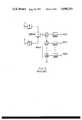
- FIG. 2shows one approach proposed by prior artisans for solving the space diversity problem.
- Antennas 1 and 2are pointing in different directions.
- Receivers 3 and 4receive the electromagnetic energy emanating from antennas 1 and 2, respectively, and pass said energy through multiplexers 5 and 6, respectively.
- the output of multiplexer 5 or 6is then selected by means of a switch 31 so the signals in the N channels from the N selected ground stations (of a possible 2N) can be processed by N high power amplifiers 32.
- Multiplexer 5comprises N unidirectional circulators 11.
- N filters 13are coupled to the N circulators 11, respectively, and channelize the energy therefrom into N channels 12, which are isolated by means of N isolators 14.
- multiplexer 6comprises N unidirectional circulators 21.
- N filters 23are coupled to the N circulaors 21, respectively, and channelize the energy therefrom into N channels 22, which are isolated by means of N isolators 24.
- FIG. 3A second approach proposed by prior artisans is illustrated in FIG. 3.
- energyis received by the two antennas 1, 2, processed by the two receivers 3, 4, and combined by means of a 3 dB coupler 9.
- a single output multiplexer 8is then used to channelize the energy into N channels 42. This is done by means of N unidirectional circulators 41 and N filters 43 coupled thereto, respectively.
- the instant inventionremedies the above problems by means of channelizing signals from two antennas 1, 2 using just a single multiplexer 7, without significantly degrading the signal-to-noise ratio.
- the present inventionis a reconfigurable multiplexeer (7) comprising N field reversible circulators (51), one for each of the N channels (52) into which the frequency bandwidth of incoming electromagnetic energy is segregated.
- Ncan be any positive integer.
- the circulators (51)are typically three-port ferrite circulators series-connected into a string. One end of the string is coupled to the first antenna (1) via a first receiver (3) and a first input isolator (43). Similarly, the second end of the string is coupled to the second antenna (2) via a second receiver (4) and a second input isolator (44).
- each channelizing filter (53)Coupled to one port of each of the circulators (51) is a channelizing filter (53).
- the output of each channelizing filter (53)passes through an output isolator (54) and a high power amplifier (HPA) (55).
- HPAhigh power amplifier
- the direction of rotation of electromagnetic energy within each circulator (51)is selectively chosen so that selected ones of the N channels (52) are assigned to the first antenna (1), while the remaining channels (52) are assigned to the second antenna (2).
- the inventionhas applicability in space diversity and polarization reuse communications systems, such as those used in conjunction with communications satellites.
- the multiplexer (7)can be dynamically reconfigured based upon the instantaneous systems requirements.
- FIG. 1is a sketch of a space diversity satellite communications system in which the present invention can be advantageously utilized
- FIG. 2is is a block diagram of a method proposed by a first group of prior artisans to address the problem solved by the present invention
- FIG. 3is a block diagram of a method proposed by a second group of prior artisans to address the problem solved by the present invention.
- FIG. 4is a block diagram of a preferred embodiment of the present invention.
- the inventionis typically used at UHF and higher frequencies, i.e., frequencies greater than or equal to 300 MHz.
- the inventionmay be used in a communications satellite or as part of a terrestrial microwave communications system.
- antennas 1 and 2are pointing in different directions.
- antennas 1 and 2are pointing in the same direction, but the polarizations of electromagnetic energy focused thereon are mutually orthogonal, e.g., LHCP and RHCP, or horizontal and vertical linear polarization, respectively. Note that in FIG. 4, the signals from antenna 1 are shown by solid lines, and the signals from antenna 2 are shown in dashed lines.
- Each receiver 3, 4typically comprises an amplifier and a down-converter. Subsequent to reception, the electromagnetic energy travels through a coax or waveguide medium.
- Each input isolator 43, 44is a circulator having one of its three ports terminated in a load resistor 45, 46, respectively.
- Each load resistor 45, 46has an impedance equal to the characteristic impedance of the transmission line medium (typically 50 ohms).
- Isolator 43serves to absorb excess signals that emanate from antenna 2.
- excess signalsmeans signals which are either out of the frequency band to which multiplexer 7 is responsive, or signals which are within the band but not passed through any given channel 52 because access to that channel via antenna 1 has already been selected. In either event, such signals are absorbed by load resistor 45.
- input isolator 44absorbs signals from antenna 1 that are either out of the band of multiplexer 7 or else within a channel 52 for which access via antenna 2 has been selected.
- the signals entering antenna 1 and antenna 2can simultaneously contain frequency component spread across the entire bandwidth of multiplexer 7.
- Filters 53are designed to divide this bandwidth into a set of N channels 52, which are typically contiguous, of equal bandwidth, and exhaustive of the overall bandwidth.
- An isolator 54is inserted in each channel 52, to buffer the multiplexer 7 from downline RF components and to prevent mismatch interference.
- Each isolator 54is a three port circulator, one of whose ports is loaded by a resistor 56 having an impedance equal to the characteristic impedance.
- An optional group delay equalizer(not illustrated) may be inserted in each channel 52 to equalize the rate of change of phase versus frequency across the frequency band allocated to that channel.
- an optional up-converter(not illustrated) may be inserted in each channel 52 if required for the particular application.
- Each circulator 51is a field reversible three-port ferrite device.
- the direction of rotation of electromagnetic energy within each circulator 51is switchable.
- FIG. 4illustrates the case where circulators 51(3) and 51(5) have been commanded to provide counter-clockwise rotation; this permits signals from antenna 2, but not from antenna 1, to be fed to corresponding filters 53(3) and 53(5). All of the other circulators 51 are commanded to provide clockwise rotation; this permits corresponding filters 53(1), 53(2), 53(4), and 53(N) to receive signals from antenna 1 but not from antenna 2.
- the direction of rotationis selected by means of a ferrite switch associated with each circulator 51; an electrical current is made to reverse direction within a coil wrapped around a ferrite element in order to change the direction of rotation of the energy within the circulator 51.
- Each filter 53is capable of channelizing the appropriate frequency channel 52 because the impedance of the input port of said filter 53 (which is coupled to the non-series-connected port of the corresponding circulator 51) is at the characteristic impedance for said frequency channel 52, but is at a much higher or much lower impedance for all other frequencies.
- the impedance of the input port of said filter 53(which is coupled to the non-series-connected port of the corresponding circulator 51) is at the characteristic impedance for said frequency channel 52, but is at a much higher or much lower impedance for all other frequencies.
- the impedance of the input port of said filter 53which is coupled to the non-series-connected port of the corresponding circulator 51
- This energymay contain signals throughout the frequency range of the multiplexer 7 bandwidth (except for those frequencies within channel 52(5), which have already been siphoned off).
- only those frequencies that are within the channel 52(3)are passed by the filter 53(3).
- the remaining frequenciesare reflected from the input port of filter 53(3) and continue their travel
Landscapes
- Engineering & Computer Science (AREA)
- Computer Networks & Wireless Communication (AREA)
- Signal Processing (AREA)
- Physics & Mathematics (AREA)
- Astronomy & Astrophysics (AREA)
- Aviation & Aerospace Engineering (AREA)
- General Physics & Mathematics (AREA)
- Radio Relay Systems (AREA)
Abstract
Description
Claims (8)
Priority Applications (1)
| Application Number | Priority Date | Filing Date | Title |
|---|---|---|---|
| US06/807,717US4688259A (en) | 1985-12-11 | 1985-12-11 | Reconfigurable multiplexer |
Applications Claiming Priority (1)
| Application Number | Priority Date | Filing Date | Title |
|---|---|---|---|
| US06/807,717US4688259A (en) | 1985-12-11 | 1985-12-11 | Reconfigurable multiplexer |
Publications (1)
| Publication Number | Publication Date |
|---|---|
| US4688259Atrue US4688259A (en) | 1987-08-18 |
Family
ID=25197034
Family Applications (1)
| Application Number | Title | Priority Date | Filing Date |
|---|---|---|---|
| US06/807,717Expired - LifetimeUS4688259A (en) | 1985-12-11 | 1985-12-11 | Reconfigurable multiplexer |
Country Status (1)
| Country | Link |
|---|---|
| US (1) | US4688259A (en) |
Cited By (25)
| Publication number | Priority date | Publication date | Assignee | Title |
|---|---|---|---|---|
| US4759051A (en)* | 1987-03-16 | 1988-07-19 | A. A. Hopeman, III | Communications system |
| EP0284442A3 (en)* | 1987-03-26 | 1989-09-27 | British Aerospace Public Limited Company | R.f. signal distribution |
| US4933680A (en)* | 1988-09-29 | 1990-06-12 | Hughes Aircraft Company | Microstrip antenna system with multiple frequency elements |
| US5032804A (en)* | 1989-05-22 | 1991-07-16 | Motorola, Inc. | Frequency agile transmitter antenna combiner |
| US5039995A (en)* | 1987-11-30 | 1991-08-13 | Gec Plessey Telecommunications Limited | Distributed antenna system |
| US5206604A (en)* | 1991-12-20 | 1993-04-27 | Harris Corporation | Broadband high power amplifier |
| US5244869A (en)* | 1990-10-23 | 1993-09-14 | Westinghouse Electric Corp. | Superconducting microwave frequency selective filter system |
| WO1994024772A1 (en)* | 1993-04-21 | 1994-10-27 | Motorola Inc. | Method and apparatus for separating channels from a radio frequency transmitter |
| EP0677884A3 (en)* | 1994-03-31 | 1996-08-07 | Ant Nachrichtentech | Frequency channel multiplexer/demultiplexer. |
| GB2306792A (en)* | 1995-10-18 | 1997-05-07 | Filtronic Ltd | Microwave multiplexer |
| US5719868A (en)* | 1995-10-05 | 1998-02-17 | Rockwell International | Dynamic distributed, multi-channel time division multiple access slot assignment method for a network of nodes |
| US5949760A (en)* | 1997-03-21 | 1999-09-07 | Rockwell International Corporation | Simultaneous channel access transmission method for a multi-hop communications radio network |
| US6192217B1 (en) | 1999-07-01 | 2001-02-20 | Assuresat, Inc. | Universal replacement communications satellite |
| US6307525B1 (en)* | 2000-02-25 | 2001-10-23 | Centurion Wireless Technologies, Inc. | Multiband flat panel antenna providing automatic routing between a plurality of antenna elements and an input/output port |
| US6313713B1 (en) | 1999-09-28 | 2001-11-06 | The United States Of America As Represented By The Secretary Of The Navy | Matched pair circulator antenna isolation circuit |
| US6466773B1 (en)* | 1997-05-15 | 2002-10-15 | Harris Corporation | Reflective power splitter for redundant receivers |
| US6512489B2 (en)* | 2000-06-23 | 2003-01-28 | Knonklijke Phiips Electronics N.V. | Antenna arrangement |
| EP1385230A1 (en)* | 2002-07-24 | 2004-01-28 | Alcatel | Re-configurable multiplexer, method for making it and branching unit for radio transceivers |
| US20040106375A1 (en)* | 2002-07-23 | 2004-06-03 | Schiff Leonard N. | Satellite communication system constituted with primary and back-up multi-beam satellites |
| US8358971B2 (en) | 2002-07-23 | 2013-01-22 | Qualcomm Incorporated | Satellite-based programmable allocation of bandwidth for forward and return links |
| US8744360B2 (en) | 2005-01-05 | 2014-06-03 | Atc Technologies, Inc. | Adaptive beam forming with multi-user detection and interference reduction in satellite communication systems and methods |
| EP2806567A1 (en)* | 2013-04-29 | 2014-11-26 | Honeywell International Inc. | A modular ferrite switch for constructing switch networks |
| US9030271B2 (en) | 2011-12-29 | 2015-05-12 | Space Systems/Loral, Llc | Microstrip manifold coupled multiplexer |
| US9472837B1 (en) | 2015-04-22 | 2016-10-18 | Honeywell International Inc. | (M+1)-for-M ferrite redundancy switch and switch system |
| US9786971B2 (en) | 2014-07-09 | 2017-10-10 | Honeywell International Inc. | Systems and methods for ferrite redundancy switch networks |
Citations (12)
| Publication number | Priority date | Publication date | Assignee | Title |
|---|---|---|---|---|
| US3273064A (en)* | 1961-04-28 | 1966-09-13 | Siemens Ag | Directional radio system with distortion correcting circuits |
| US3422438A (en)* | 1965-11-30 | 1969-01-14 | Arthur E Marston | Conjugate pair feed system for antenna array |
| US3636452A (en)* | 1969-08-28 | 1972-01-18 | Licentia Gmbh | Radio relay system |
| US3646467A (en)* | 1970-11-02 | 1972-02-29 | Raytheon Co | Solid-state electromagnetic energy amplifier system |
| US3696421A (en)* | 1969-06-06 | 1972-10-03 | Bell Telephone Labor Inc | Space diversity phased array retransmission system using time division |
| US3865990A (en)* | 1972-03-22 | 1975-02-11 | Siemens Ag | Radio relay systems |
| US4039947A (en)* | 1976-06-29 | 1977-08-02 | Bell Telephone Laboratories, Incorporated | Protection switching system for microwave radio |
| US4041389A (en)* | 1975-07-09 | 1977-08-09 | Gte Automatic Electric Laboratories Incorporated | Nonfrequency-converting microwave radio repeater using a low power consumption amplifier |
| US4109202A (en)* | 1976-08-24 | 1978-08-22 | Rca Corporation | Traffic switching in communications satellites |
| US4159454A (en)* | 1977-12-30 | 1979-06-26 | The United States Of America As Represented By The Secretary Of The Air Force | Plug-in filter network for separating a communication frequency into discrete frequency channels |
| US4161694A (en)* | 1976-06-28 | 1979-07-17 | Siemens Aktiengesellschaft | Radio relay channel branch cascade exhibiting uniform transit-time-and-attenuation-characteristics of all channels |
| US4206464A (en)* | 1976-09-17 | 1980-06-03 | Licentia Patent-Verwaltungs-G.M.B.H. | Arrangement including circulators for connecting a plurality of transmitters and receivers to a common antenna |
- 1985
- 1985-12-11USUS06/807,717patent/US4688259A/ennot_activeExpired - Lifetime
Patent Citations (12)
| Publication number | Priority date | Publication date | Assignee | Title |
|---|---|---|---|---|
| US3273064A (en)* | 1961-04-28 | 1966-09-13 | Siemens Ag | Directional radio system with distortion correcting circuits |
| US3422438A (en)* | 1965-11-30 | 1969-01-14 | Arthur E Marston | Conjugate pair feed system for antenna array |
| US3696421A (en)* | 1969-06-06 | 1972-10-03 | Bell Telephone Labor Inc | Space diversity phased array retransmission system using time division |
| US3636452A (en)* | 1969-08-28 | 1972-01-18 | Licentia Gmbh | Radio relay system |
| US3646467A (en)* | 1970-11-02 | 1972-02-29 | Raytheon Co | Solid-state electromagnetic energy amplifier system |
| US3865990A (en)* | 1972-03-22 | 1975-02-11 | Siemens Ag | Radio relay systems |
| US4041389A (en)* | 1975-07-09 | 1977-08-09 | Gte Automatic Electric Laboratories Incorporated | Nonfrequency-converting microwave radio repeater using a low power consumption amplifier |
| US4161694A (en)* | 1976-06-28 | 1979-07-17 | Siemens Aktiengesellschaft | Radio relay channel branch cascade exhibiting uniform transit-time-and-attenuation-characteristics of all channels |
| US4039947A (en)* | 1976-06-29 | 1977-08-02 | Bell Telephone Laboratories, Incorporated | Protection switching system for microwave radio |
| US4109202A (en)* | 1976-08-24 | 1978-08-22 | Rca Corporation | Traffic switching in communications satellites |
| US4206464A (en)* | 1976-09-17 | 1980-06-03 | Licentia Patent-Verwaltungs-G.M.B.H. | Arrangement including circulators for connecting a plurality of transmitters and receivers to a common antenna |
| US4159454A (en)* | 1977-12-30 | 1979-06-26 | The United States Of America As Represented By The Secretary Of The Air Force | Plug-in filter network for separating a communication frequency into discrete frequency channels |
Cited By (31)
| Publication number | Priority date | Publication date | Assignee | Title |
|---|---|---|---|---|
| US4759051A (en)* | 1987-03-16 | 1988-07-19 | A. A. Hopeman, III | Communications system |
| EP0284442A3 (en)* | 1987-03-26 | 1989-09-27 | British Aerospace Public Limited Company | R.f. signal distribution |
| US5039995A (en)* | 1987-11-30 | 1991-08-13 | Gec Plessey Telecommunications Limited | Distributed antenna system |
| US4933680A (en)* | 1988-09-29 | 1990-06-12 | Hughes Aircraft Company | Microstrip antenna system with multiple frequency elements |
| US5032804A (en)* | 1989-05-22 | 1991-07-16 | Motorola, Inc. | Frequency agile transmitter antenna combiner |
| US5244869A (en)* | 1990-10-23 | 1993-09-14 | Westinghouse Electric Corp. | Superconducting microwave frequency selective filter system |
| US5206604A (en)* | 1991-12-20 | 1993-04-27 | Harris Corporation | Broadband high power amplifier |
| WO1994024772A1 (en)* | 1993-04-21 | 1994-10-27 | Motorola Inc. | Method and apparatus for separating channels from a radio frequency transmitter |
| EP0677884A3 (en)* | 1994-03-31 | 1996-08-07 | Ant Nachrichtentech | Frequency channel multiplexer/demultiplexer. |
| US5691987A (en)* | 1994-03-31 | 1997-11-25 | Ant Nachrichtentechnik Gmbh | Frequency-channel multiplexer and demultiplexer |
| US5719868A (en)* | 1995-10-05 | 1998-02-17 | Rockwell International | Dynamic distributed, multi-channel time division multiple access slot assignment method for a network of nodes |
| GB2306792A (en)* | 1995-10-18 | 1997-05-07 | Filtronic Ltd | Microwave multiplexer |
| US5949760A (en)* | 1997-03-21 | 1999-09-07 | Rockwell International Corporation | Simultaneous channel access transmission method for a multi-hop communications radio network |
| US6466773B1 (en)* | 1997-05-15 | 2002-10-15 | Harris Corporation | Reflective power splitter for redundant receivers |
| US6192217B1 (en) | 1999-07-01 | 2001-02-20 | Assuresat, Inc. | Universal replacement communications satellite |
| US6313713B1 (en) | 1999-09-28 | 2001-11-06 | The United States Of America As Represented By The Secretary Of The Navy | Matched pair circulator antenna isolation circuit |
| US6307525B1 (en)* | 2000-02-25 | 2001-10-23 | Centurion Wireless Technologies, Inc. | Multiband flat panel antenna providing automatic routing between a plurality of antenna elements and an input/output port |
| US6512489B2 (en)* | 2000-06-23 | 2003-01-28 | Knonklijke Phiips Electronics N.V. | Antenna arrangement |
| US8358971B2 (en) | 2002-07-23 | 2013-01-22 | Qualcomm Incorporated | Satellite-based programmable allocation of bandwidth for forward and return links |
| US8744344B2 (en) | 2002-07-23 | 2014-06-03 | Qualcomm Incorporated | Satellite communication system constituted with primary and back-up multi-beam satellites |
| US20040106375A1 (en)* | 2002-07-23 | 2004-06-03 | Schiff Leonard N. | Satellite communication system constituted with primary and back-up multi-beam satellites |
| US7379758B2 (en)* | 2002-07-23 | 2008-05-27 | Qualcomm Incorporated | Satellite communication system constituted with primary and back-up multi-beam satellites |
| US20090051589A1 (en)* | 2002-07-23 | 2009-02-26 | Qualcomm Incorporated | Satellite communication system constituted with primary and back-up multi-beam satellites |
| US20050176383A1 (en)* | 2002-07-24 | 2005-08-11 | Alcatel | Re-configurable multiplexer, method for making it and branching unit for terrestrial radio links |
| EP1385230A1 (en)* | 2002-07-24 | 2004-01-28 | Alcatel | Re-configurable multiplexer, method for making it and branching unit for radio transceivers |
| US8744360B2 (en) | 2005-01-05 | 2014-06-03 | Atc Technologies, Inc. | Adaptive beam forming with multi-user detection and interference reduction in satellite communication systems and methods |
| US9030271B2 (en) | 2011-12-29 | 2015-05-12 | Space Systems/Loral, Llc | Microstrip manifold coupled multiplexer |
| EP2806567A1 (en)* | 2013-04-29 | 2014-11-26 | Honeywell International Inc. | A modular ferrite switch for constructing switch networks |
| US9166267B2 (en) | 2013-04-29 | 2015-10-20 | Honeywell International Inc. | Modular ferrite switch for constructing switch networks |
| US9786971B2 (en) | 2014-07-09 | 2017-10-10 | Honeywell International Inc. | Systems and methods for ferrite redundancy switch networks |
| US9472837B1 (en) | 2015-04-22 | 2016-10-18 | Honeywell International Inc. | (M+1)-for-M ferrite redundancy switch and switch system |
Similar Documents
| Publication | Publication Date | Title |
|---|---|---|
| US4688259A (en) | Reconfigurable multiplexer | |
| AP895A (en) | Multifunction interactive communications system with circularly/elliptically polarized signal transmission and reception. | |
| US3735266A (en) | Method and apparatus for reducing crosstalk on cross-polarized communication links | |
| US4689625A (en) | Satellite communications system and method therefor | |
| US6233435B1 (en) | Multi-function interactive communications system with circularly/elliptically polarized signal transmission and reception | |
| US6510317B1 (en) | Satellite digital audio radio service tuner architecture for reception of satellite and terrestrial signals | |
| US5978652A (en) | Common direct broadcasting service system | |
| US4956643A (en) | Transponder with selective antenna beam using shared antenna feed elements | |
| US6208312B1 (en) | Multi-feed multi-band antenna | |
| US20140038515A1 (en) | High throughput satellite | |
| US4821046A (en) | Dual band feed system | |
| AU747622B2 (en) | Device for transmitting and receiving microwaves subjected to circular polarisation | |
| US5615407A (en) | Satellite communications system using an intermediate satellite to provide same frequency uplink and downlink | |
| US4535476A (en) | Offset geometry, interference canceling receiver | |
| US3631494A (en) | Retransmission system | |
| KR100502496B1 (en) | Repeating apparatus for satellite broadcasting | |
| US20030134594A1 (en) | Downlink switching mechanism for a satellite | |
| AU748478B2 (en) | Circuit and method for receiving or transmitting microwaves | |
| CN118646471A (en) | Satellite communication antenna and signal transmission method applicable to high and low orbit satellites | |
| Kurimura | Satellite communications in Japan | |
| Kefalas | A phased-array ground terminal for satellite communications | |
| KR970007605B1 (en) | Radio frequency broadcasting systems | |
| Brand | West German Microwave Activity-State of the Art in Satellite Communications | |
| Malarky et al. | Canadian technology development for military EHF communications payloads | |
| Inoue et al. | 30/20‐ghz band earth station for domestic satellite communication |
Legal Events
| Date | Code | Title | Description |
|---|---|---|---|
| AS | Assignment | Owner name:FORD AEROSPACE & COMMUNICATIONS CORPORATION, 300 R Free format text:ASSIGNMENT OF ASSIGNORS INTEREST.;ASSIGNOR:EDRIDGE, MICHAEL J.;REEL/FRAME:004493/0675 Effective date:19851206 | |
| STCF | Information on status: patent grant | Free format text:PATENTED CASE | |
| FPAY | Fee payment | Year of fee payment:4 | |
| AS | Assignment | Owner name:SPACE SYSTEMS/LORAL, INC., 3825 FABIAN WAY, PALO A Free format text:ASSIGNMENT OF ASSIGNORS INTEREST.;ASSIGNOR:FORD AEROSPACE CORPORATION, A CORP. OF DELAWARE;REEL/FRAME:005635/0274 Effective date:19910215 | |
| FEPP | Fee payment procedure | Free format text:PAYOR NUMBER ASSIGNED (ORIGINAL EVENT CODE: ASPN); ENTITY STATUS OF PATENT OWNER: LARGE ENTITY | |
| FPAY | Fee payment | Year of fee payment:8 | |
| FEPP | Fee payment procedure | Free format text:PAYOR NUMBER ASSIGNED (ORIGINAL EVENT CODE: ASPN); ENTITY STATUS OF PATENT OWNER: LARGE ENTITY Free format text:PAYER NUMBER DE-ASSIGNED (ORIGINAL EVENT CODE: RMPN); ENTITY STATUS OF PATENT OWNER: LARGE ENTITY | |
| FPAY | Fee payment | Year of fee payment:12 | |
| AS | Assignment | Owner name:BANK OF AMERICA NA., AS COLLATERAL AGENT, NORTH CA Free format text:NOTICE OF GRANT OF SECURITY INTEREST;ASSIGNOR:SPACE SYSTEMS/LORAL INC.;REEL/FRAME:012946/0052 Effective date:20011221 | |
| AS | Assignment | Owner name:SPACE SYSTEMS/LORAL, INC., CALIFORNIA Free format text:RELEASE OF SECURITY INTEREST;ASSIGNOR:BANK OF AMERICA, N.A.;REEL/FRAME:016153/0507 Effective date:20040802 |