US4686479A - Apparatus and control kit for analyzing blood sample values including hematocrit - Google Patents
Apparatus and control kit for analyzing blood sample values including hematocritDownload PDFInfo
- Publication number
- US4686479A US4686479AUS06/757,573US75757385AUS4686479AUS 4686479 AUS4686479 AUS 4686479AUS 75757385 AUS75757385 AUS 75757385AUS 4686479 AUS4686479 AUS 4686479A
- Authority
- US
- United States
- Prior art keywords
- sample
- standardizing
- concentration
- flow path
- conductivity
- Prior art date
- Legal status (The legal status is an assumption and is not a legal conclusion. Google has not performed a legal analysis and makes no representation as to the accuracy of the status listed.)
- Expired - Lifetime
Links
- 238000005534hematocritMethods0.000titleclaimsabstractdescription98
- 210000004369bloodAnatomy0.000titleclaimsabstractdescription43
- 239000008280bloodSubstances0.000titleclaimsabstractdescription43
- 239000000523sampleSubstances0.000claimsabstractdescription146
- 239000012530fluidSubstances0.000claimsabstractdescription33
- 239000007788liquidSubstances0.000claimsabstractdescription18
- 230000000694effectsEffects0.000claimsabstractdescription11
- 230000002708enhancing effectEffects0.000claimsabstractdescription4
- 239000000243solutionSubstances0.000claimsdescription39
- PEDCQBHIVMGVHV-UHFFFAOYSA-NGlycerineChemical compoundOCC(O)COPEDCQBHIVMGVHV-UHFFFAOYSA-N0.000claimsdescription21
- 238000000034methodMethods0.000claimsdescription15
- 229920005862polyolPolymers0.000claimsdescription6
- 150000003077polyolsChemical group0.000claimsdescription6
- 239000003795chemical substances by applicationSubstances0.000claimsdescription5
- 150000002334glycolsChemical class0.000claimsdescription3
- 239000007864aqueous solutionSubstances0.000claimsdescription2
- 230000008878couplingEffects0.000claimsdescription2
- 238000010168coupling processMethods0.000claimsdescription2
- 238000005859coupling reactionMethods0.000claimsdescription2
- 238000010200validation analysisMethods0.000claimsdescription2
- 238000005259measurementMethods0.000abstractdescription12
- 238000001514detection methodMethods0.000abstractdescription3
- 150000002500ionsChemical class0.000description29
- FKNQFGJONOIPTF-UHFFFAOYSA-NSodium cationChemical compound[Na+]FKNQFGJONOIPTF-UHFFFAOYSA-N0.000description27
- 229910001415sodium ionInorganic materials0.000description27
- 239000000306componentSubstances0.000description17
- 239000003792electrolyteSubstances0.000description13
- 239000007789gasSubstances0.000description13
- 239000011734sodiumSubstances0.000description13
- 239000002699waste materialSubstances0.000description8
- BHPQYMZQTOCNFJ-UHFFFAOYSA-NCalcium cationChemical compound[Ca+2]BHPQYMZQTOCNFJ-UHFFFAOYSA-N0.000description7
- 238000011109contaminationMethods0.000description6
- 239000003623enhancerSubstances0.000description6
- 239000012503blood componentSubstances0.000description5
- 239000011575calciumSubstances0.000description5
- 239000012088reference solutionSubstances0.000description5
- 230000006870functionEffects0.000description4
- 238000010438heat treatmentMethods0.000description4
- 239000000203mixtureSubstances0.000description4
- 229910001220stainless steelInorganic materials0.000description4
- 239000010935stainless steelSubstances0.000description4
- 238000012937correctionMethods0.000description3
- DGAQECJNVWCQMB-PUAWFVPOSA-MIlexoside XXIXChemical compoundC[C@@H]1CC[C@@]2(CC[C@@]3(C(=CC[C@H]4[C@]3(CC[C@@H]5[C@@]4(CC[C@@H](C5(C)C)OS(=O)(=O)[O-])C)C)[C@@H]2[C@]1(C)O)C)C(=O)O[C@H]6[C@@H]([C@H]([C@@H]([C@H](O6)CO)O)O)O.[Na+]DGAQECJNVWCQMB-PUAWFVPOSA-M0.000description2
- 238000004364calculation methodMethods0.000description2
- HGAZMNJKRQFZKS-UHFFFAOYSA-Nchloroethene;ethenyl acetateChemical compoundClC=C.CC(=O)OC=CHGAZMNJKRQFZKS-UHFFFAOYSA-N0.000description2
- 238000004140cleaningMethods0.000description2
- 230000004044responseEffects0.000description2
- 238000007789sealingMethods0.000description2
- 229910052708sodiumInorganic materials0.000description2
- 239000012086standard solutionSubstances0.000description2
- 238000011144upstream manufacturingMethods0.000description2
- 238000004804windingMethods0.000description2
- HTTJABKRGRZYRN-UHFFFAOYSA-NHeparinChemical compoundOC1C(NC(=O)C)C(O)OC(COS(O)(=O)=O)C1OC1C(OS(O)(=O)=O)C(O)C(OC2C(C(OS(O)(=O)=O)C(OC3C(C(O)C(O)C(O3)C(O)=O)OS(O)(=O)=O)C(CO)O2)NS(O)(=O)=O)C(C(O)=O)O1HTTJABKRGRZYRN-UHFFFAOYSA-N0.000description1
- GRYLNZFGIOXLOG-UHFFFAOYSA-NNitric acidChemical compoundO[N+]([O-])=OGRYLNZFGIOXLOG-UHFFFAOYSA-N0.000description1
- 239000002202Polyethylene glycolSubstances0.000description1
- NPYPAHLBTDXSSS-UHFFFAOYSA-NPotassium ionChemical compound[K+]NPYPAHLBTDXSSS-UHFFFAOYSA-N0.000description1
- 208000007536ThrombosisDiseases0.000description1
- 238000004458analytical methodMethods0.000description1
- 208000007502anemiaDiseases0.000description1
- 239000012062aqueous bufferSubstances0.000description1
- 210000000601blood cellAnatomy0.000description1
- 239000000872bufferSubstances0.000description1
- 239000008366buffered solutionSubstances0.000description1
- 229910001424calcium ionInorganic materials0.000description1
- 210000004027cellAnatomy0.000description1
- 230000008859changeEffects0.000description1
- 238000006243chemical reactionMethods0.000description1
- 238000005345coagulationMethods0.000description1
- 230000015271coagulationEffects0.000description1
- 238000004891communicationMethods0.000description1
- 230000006835compressionEffects0.000description1
- 238000007906compressionMethods0.000description1
- 230000007547defectEffects0.000description1
- 230000002950deficientEffects0.000description1
- 238000013461designMethods0.000description1
- 238000003745diagnosisMethods0.000description1
- 238000010586diagramMethods0.000description1
- 201000010099diseaseDiseases0.000description1
- 208000037265diseases, disorders, signs and symptomsDiseases0.000description1
- 230000009977dual effectEffects0.000description1
- 210000003743erythrocyteAnatomy0.000description1
- 230000005284excitationEffects0.000description1
- 229960002897heparinDrugs0.000description1
- 229920000669heparinPolymers0.000description1
- GPRLSGONYQIRFK-UHFFFAOYSA-NhydronChemical compound[H+]GPRLSGONYQIRFK-UHFFFAOYSA-N0.000description1
- 239000012528membraneSubstances0.000description1
- 229910052751metalInorganic materials0.000description1
- 239000002184metalSubstances0.000description1
- 229910017604nitric acidInorganic materials0.000description1
- 150000002894organic compoundsChemical class0.000description1
- 230000002572peristaltic effectEffects0.000description1
- 230000010363phase shiftEffects0.000description1
- 229920001223polyethylene glycolPolymers0.000description1
- 229920001451polypropylene glycolPolymers0.000description1
- 229910001414potassium ionInorganic materials0.000description1
- 238000011160researchMethods0.000description1
- 239000012488sample solutionSubstances0.000description1
- 230000035945sensitivityEffects0.000description1
- 238000000926separation methodMethods0.000description1
- 238000012546transferMethods0.000description1
- 230000007704transitionEffects0.000description1
- 230000000007visual effectEffects0.000description1
- 238000003466weldingMethods0.000description1
Images


Classifications
- G—PHYSICS
- G01—MEASURING; TESTING
- G01N—INVESTIGATING OR ANALYSING MATERIALS BY DETERMINING THEIR CHEMICAL OR PHYSICAL PROPERTIES
- G01N33/00—Investigating or analysing materials by specific methods not covered by groups G01N1/00 - G01N31/00
- G01N33/48—Biological material, e.g. blood, urine; Haemocytometers
- G01N33/483—Physical analysis of biological material
- G01N33/487—Physical analysis of biological material of liquid biological material
- G01N33/49—Blood
- G01N33/4915—Blood using flow cells
Definitions
- This inventionrelates to blood analyzers used to measure various components in a blood sample, for example in medical diagnosis and research.
- the ratio of the volume of packed red blood cells from a whole blood sample to the total sample volumeis a useful measurement for diagnosing anemia and other disease conditions. That ratio usually is referred to as the "hematocrit ratio” or the “hematocrit value”, and it is usually determined by centrifuging a whole blood sample to separate cells from plasma. It is known that, all other things being constant, the conductivity of a blood sample varies as a function of its hematocrit value, but other blood components, notably electrolytes, influence conductivity significantly, and the conductivity of those components must be accurately accounted for if a reliable hematocrit value is to be derived from conductivity readings.
- Electrodespositioned along a flow path. When whole blood is introduced in the flow path, the electrodes provide a reading of the desired blood characteristic.
- electrodesare available to provide electrical signals representative of various blood components such as sodium ion concentration ("[Na + ]”), potassium ion concentration (“[K + ]”), calcium ion concentration (“[Ca + ]”), hydrogen ion concentration ("pH”), partial pressure attributed to O 2 (“PO 2 "), and partial pressure attributed to CO 2 (“PCO 2 ").
- the hematocrit level of a blood sampleis measured by flowing the sample along a liquid flow path and using means in the flow path to obtain electrical signals representative of the sample's electrical conductivity and of the concentration of an ion species in the sample.
- Standardizing solutionis introduced in the same flow path, either before or after the sample measurement.
- the standardizing solutionhas a known ion species concentration and a conductivity indicative of a known equivalent hematocrit value; "equivalent" hematocrit value is used in this application to mean the hematocrit level of a blood sample having a conductivity corresponding to that of the standardizing solution, even though the standardizing solution contains no whole blood cells and has an actual hematocrit value of 0.
- a tentative sample hematocrit valueis derived from the sample and standardizing conductivity signals, with reference to the known equivalent standardizing hematocrit value. Then the tentative hematocrit value is corrected with reference to the sample and standardizing ion concentration signals and to the known standardizing solution ion concentration value.
- an external validation of the apparatusis provided from time to time by introducing a control solution into the flow path, which is described below in connection with the third aspect of the invention.
- conductivity of solutions in the flow pathis obtained by: (a) providing electrodes in the flow path coupled to a constant current AC circuit via a transformer; (b) applying an AC signal from the AC circuit to the electrodes via the transformer; and (c) detecting reflected impedance in the AC circuit.
- the methodcomprises: (a) obtaining the electrical signals representative of standardizing conductivity and standardizing ion concentration; (b) storing signals representative of the known standardizing equivalent hematocrit value and the known standardizing ion concentration value; (c) obtaining the electrical signals representative of sample concentration and standardizing ion concentration; (d) comparing the sample and the standardizing ion concentration signals with reference to the stored known standardizing value signal, to derive a signal representative of sample ion concentration value; (e) comparing the sample and the standardizing conductivity signals with reference to the stored standardizing hematocrit value signal to derive a signal representative of a tentative sample hematocrit value; and (f) correcting the tentative sample hematocrit value signal with reference to the sample ion concentration signal and the stored standardizing ion concentration value signal.
- Preferred ion species for use in the methodare Na + or Cl - .
- the inventionalso features, in another aspect, apparatus for determining hematocrit value in a blood sample comprising: (1) means for providing a fluid flow path; (2) means in the flow path for providing an electrical signal representative of the conductivity of liquid passing along the flow path; (3) means in the flow path for providing a signal representative of the concentration of an ion species in liquid passing along the flow path; (4) means for introducing the blood sample into the flow path to obtain a signal representative of sample conductivity and of sample ion species concentration; (5) means for introducing into the flow path a standardizing solution having a known concentration of an ion species and having a conductivity representative of a known equivalent hematocrit value; (6) means for deriving a signal representative of a tentative sample hematocrit value from the sample conductivity signal, with reference to the standardizing conductivity signal, and to the standardizing equivalent hematocrit value; and (7) means for correcting the tentative sample hematocrit value with reference to the standardizing and sample ion concentration signals and to the known standardizing
- the apparatusincludes: (a) means for storing either the sample or the standardizing conductivity signal, and means for comparing the conductivity signals with reference to the known standardizing equivalent hematocrit value to generate a signal representative of the tentative sample hematocrit value; and (b) means for correcting the tentative sample hematocrit value signal including means for storing either the standardizing or the sample ion concentration signal and comparing the ion concentration signals with reference to the known standardizing ion concentration value.
- the apparatuscomprises at least two standardizing solutions, each of which has a conductivity indicative of a known equivalent hematocrit value and a known ion concentration.
- the conductivity measuring meanscomprises electrodes in the flow path, a constant current AC circuit coupled to the electrodes via a transformer and means for detecting the reflected impedance in the AC circuit.
- the conductivity signal-generating meanscomprises: (1) a first transformer for coupling the AC circuit to the electrodes; and (2) a second transformer for maintaining constant current in the AC circuit; means establishing a loop between the electrodes and means, connected in the loop between the second transformer and the electrodes, selected to compensate for inherent capacitance at the electrode/sample interface.
- the apparatuscomprises an ion species sensing electrode positioned in the flow path and connected via an electrical output circuit connected to the input of a multiplexer, the impedance detecting means also being connected to the input of the multiplexer, the multiplexer having an output means connected via an analog-to-digital converter to a means for storing and comparing signals, and to the means for correcting sample conductivity.
- the inventionfeatures a control solution kit for evaluating the hematocrit detection apparatus.
- the solutioncomprises an aqueous solution of the ion species (e.g. Na + or Cl - ) at a known concentration; and an ion activity enhancing agent (e.g. a polyol selected from glycerol and polyalkyl glycols).
- the solutionhas a conductivity representative of a known equivalent hematocrit level, and both the ion concentration and the equivalent hematocrit value preferably are within physiological ranges (e.g., [Na + ] is between 130-150 mM, and hematocrit is between 40 and 55%).
- the hematocrit measurement aspects of the inventionprovide rapid, accurate highly automated measurements of the hematocrit level, without the need for the analyzer user to store whole blood standards .
- the inventionfeatures an electrode clip for use in apparatus for determining the concentration of a component of a blood sample, the apparatus comprising a means defining a sample flow path, means in the flow path generating an electrical signal representative of the component concentration, and means for moving fluid along the path under pressure, the flow path comprising an electrode block having an opening for receiving an electrode to contact fluid in the path, the opening communicating with the flow path.
- the signal generating meanscomprises an electrode attached to a clip means for resiliently and removably forcing the electrode into the block opening to effectively seal the opening against pressure leakage.
- the clip meanscomprises an electrode support slidably inserted through a retainer, the retainer comprising a means for cooperatively engaging the electrode block, and the clip means further comprises a biasing means for biasing the electrode support away from the retainer against the block.
- the retainercomprises a deflectable latch element cooperatively engaging the electrode block.
- the electrode clipenables an operator to quickly remove or insert any one electrode using a simple, one-handed operation in an area of the apparatus where there is little space available for manual manipulations.
- the inventionfeatures a removable septum assembly for use in a blood sample component measuring apparatus in which at least two standardizing solutions are introduced into the flow path.
- the septum assemblycomprises: (a) chamber-defining members, which define a plurality of chambers, the members being permanently attached to each other; and (b) flexible septa positioned between the chambers, each septum having a slit, the slits being aligned to sealably receive therethrough an elongated probe connected to the apparatus flow path, one chamber being connected to a flush fluid and each remaining chamber being connected to a standardizing fluid (liquid or gas) introducing means, the septum assembly being removably attached as a unit to the apparatus which includes means for releasably attaching the septum assembly in position to receive the probe through the slits.
- the releasable attachment meanscomprises a post on the base of the septum assembly and a means on the apparatus for cooperatively engaging the post, the engaging means comprising a pair of elongated resilient spring means spaced to receive and releasably engage the post therebetween.
- Each septumcomprises an annular ridge positioned radially outwardly of, and concentrically with, the slit to seal against a chamber-defining member.
- Each chamber-defining membercomprises an inlet means
- the standardizing fluid introducing meanscomprises an integral standardizing fluid-flow-path manifold connector having a plurality of outlets, each of which is positioned and sized to removably seal to an inlet means.
- Each inlet meanscomprises a cylindrical inlet positioned in a recess in the chamber-defining member, and the manifold connector is cooperatively sized and shaped to fit within those recesses.
- the septum assemblyis particularly advantageous in that it is a single unit that can be pre-tested by the manufacturer before use, and it does not require customer assembly.
- the partis relatively inexpensive to produce and therefore it can be disposed of as the septa became worn.
- the use of a manifoldenables a quick connection to the septum assembly and reduces the risk of misconnections.
- the inventionfeatures an electrode block assembly apparatus for determining the concentration of a component of a blood sample having a means defining a sample flow path, means in the flow path generating an electrical signal representative of the conponent concentration, and means for driving fluid along the path.
- the flow pathcomprises a heater path means, an electrode block path means connected immediately downstream of the heater path means, and a reference path means connected immediately downstream of the electrode path means.
- the heater path means, the electrode path means, and the reference path meansare connected as a single unit, which is removable from the apparatus.
- the heater path means, the electrode path means, and the reference path meanscomprise attachment means allowing them to be severed from each other, whereby, one path means can be replaced by removing the unit, removing the path means from the unit, and replacing the path means.
- various parts of the analyzersuch as the septum assembly, the electrodes, and the electrode block are designed so that when they become worn out, or clogged, they can be replaced easily and quickly, minimizing down time on the analyzer.
- FIG. 1is a front view of a blood analyzer.
- FIG. 2is a diagrammatic representation of the fluid flow path and some of the electrical components of the analyzer of FIG. 1.
- FIG. 3is a side view, in section, of the septum assembly and septum mounting plate of the analyzer of FIG. 1.
- FIG. 4is a view along 4--4 of FIG. 5.
- FIG. 4Ais a section of a septum from the septum assembly of FIG. 3.
- FIG. 5is an exploded view, with parts broken away, of the septum assembly and mounting plate of FIG. 3.
- FIG. 6is a side view of the electrode holder assembly of the analyzer of FIG. 1.
- FIG. 7is a view, in section, along 7--7 of FIG. 6.
- FIG. 8is a side view of the holder assembly of FIG. 6 with parts exploded, broken away, and in section.
- FIG. 8Ais a view of the reference block of the assembly of FIG. 6, taken along 8A--8A of FIG. 8.
- FIG. 9is a view along 9--9 of FIG. 8 with parts broken away and in section.
- FIG. 10is a view, in section, along 10--10 of FIG. 8.
- FIG. 11is a plan side view of an electrode clip for use in the assembly of FIG. 6.
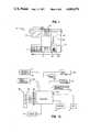
- FIG. 12is a diagrammatic representation of electronic components and functions related to the hematocrit detector of the analyzer of FIG. 1.
- FIG. 12Ais a graph of the reciprocal of resistivity versus 1/(1-hematocrit value).
- FIG. 13is a diagrammatic representation of the electrical functions of the analyzer of FIG. 1.
- Analyzer 10 of FIG. 1provides for measurement of the concentrations of certain electrolytes and gases in a small (e.g. less than about 0.25 ml) sample of whole blood that has been treated (e.g. with heparin) to prevent coagulation.
- the treated sampleis drawn from its container through a probe 20, along a sample flow path, and out a waste outlet 28 (FIG. 2).
- Readings of sample PO 2 , PCO 2 , [Na + ], [K + ], [Ca ++ ], and pHare provided on a C.R.T. display 12 and a tape printer 14.
- the same flow pathincludes means to provide a measurement and readout of the sample hematocrit value.
- the above measurementsare performed as described in greater detail below, using electrodes and associated components that yield an electric signal representative of the characteristic being measured.
- the electrodesare standardized periodically with standard gases from replaceable cylinders and with standard fluids from a replaceable fluid pack 18 whose components and operation are also described below.
- the operation of the electrodes and standardizing apparatusis controlled by a computer 130 (FIG. 13) in response to a control program and to the operator's entries on keypad 16.
- probe 20is a hollow elongated metal tube (e.g. stainless steel) having a fluid inlet 21 at one end and connected at the other end to a fluid flow path.
- the furthest longitudinal extension of the probe in the direction of arrow Ais shown in FIG. 2, with probe inlet 21 positioned outside the septum assembly, immersed in a sample 26 that is to be drawn through the inlet and along the flow path.
- FIG. 2diagrams the sample flow path through an electrode assembly (best shown in FIGS. 6-10 and described in greater detail below) that includes: a heater block 30 heated by a resistance heater 160; a series of six electrodes, 31, 33, 35, 37, 39, and 41 in an electrode block 80 that enable generation of signals representative of PO 2 , PCO 2 , pH, [Ca ++ ], [K +] , and [Na + ], respectively; and a reference block 105.
- the external, mechanical configuration of the electrodesis described below; the electrochemical principles and composition of the electrodes are conventional.
- the sampleflows to waste outlet 28.
- the fluid flowis drawn along the path by a peristaltic pump 29, driven by stepper motor 230 under the control of controller 229.
- air detectorsto sense conductivity changes representative of the change from air to liquid, thereby providing an indication of air/liquid transitions and thus to signal changes from one fluid to another and to verify sample and standard positioning.
- one air detector 32is positioned in heating block 30, and a detector 69 located in heater block 30 serves as a hematocrit level detector as described in greater detail below.
- a third air detector 103is located in the electrode block.
- a clamp electrode 43is positioned upstream from waste outlet 28 to connect to circuitry that minimizes the common mode voltage range and thereby improves the sensitivity and stability of the electrode measurement.
- the analyzerhas been designed particularly to flow the various standard fluids through the flow path and to flush the flow path, while minimizing any opportunity for contamination between standards, or between a standard and a blood sample.
- the standardsare assigned to specific flow paths and chambers in septum assembly 24, and from there, the standards flow through the above-described sample flow path to waste outlet 28.
- the various standards and their flow pathsare:
- G Awhich is a source of gas having known PO 2 and PCO 2 composition, connected via metering solenoid valves 46 (sold by Lee Company, Westbrook, Conn.) to a humidifier 47 and thence, via line 48 to chamber 49 of the septum assembly 24.
- G Awhich is similar to G A , having different PO 2 and PCO 2 composition, thereby enabling standardization of those two electrodes;
- G Bcommunicates with chamber 49 of septum assembly 24 via solenoid valves 46', humidifer 47' and line 48'.
- pH Aa liquid of known pH that flows via line 53 to chamber 54 of septum assembly 24;
- Standard pH Bhas a total conductivity indicative of a known equivalent hematocrit value.
- a solution having a known conductivitycan be treated as the equivalent of a whole blood sample having a specific "equivalent hematocrit value.”
- E Aan electrolyte standard having a known [Na + ], [K +] , and [Ca ++ ] and also having a total conductivity indicative of a known equivalent hematocrit value different from the value of pH B ; E A flows via line 56 to septum assembly chamber 57.
- E Ban electrolyte standard having a known [Na + ], [K + ], and [Ca ++ ], different from those of E A ; standard E B flows via line 58 to septum assembly chamber 60.
- composition of the various standard solutionsis given in more detail below.
- Each of lines 53, 53', 56, and 58flows through a pinch valve 51 that is controlled by D.C. motor 63, and controller 64 to shut those lines selectively and separately when they are not in use.
- Each of lines 53, 53', 56, and 58flows through a preheater to warm the standard solutions somewhat before they enter the heating block 30.
- a flush line 61bypasses pinch valve 51 and flows through preheater 52 to septum assembly chamber 62.
- Lines 48, 48', 61, 56, 58, 53, and 53'terminate in a rigid multi-plug connector 161 that is adapted to cooperate with the septum assembly 24 so that all of the lines can be connected simultaneously.
- connector 161is shaped to fit within recesses of the septum assembly surrounding each inlet to a septum assembly chamber and, when connector 161 is properly positioned, an outlet from each of the 1ines 48, 53, 53', 56, 58, and 61 removably seals to the appropriate septum inlet by overlapping it.
- a high molarity reference solution (Ref)flows through line 67 where it contacts reference electrode 34, and from there into the above sample flow path between clamp electrode 43 and waste outlet 28.
- the use of an open reference junctioni.e., a junction that is not enclosed in a membrane) enables the use of a low pressure flow for reference solution, and thereby reduces any possibility of contamination of the sample flow path or the electrode sensors by reference solution.
- the dotted line 64indicates the region of the analyzer bathed in air from heater 66 driven by fan 65 (connected to controller 66' and fan-fail monitor 65') to stabilize temperature.
- septum assembly 24electrode assembly 68 (FIG. 6); and hematocrit detection via conductivity detector 69.
- removable septum assembly 24has chambers 49, 54, 55, 57, and 60, and 62 which are separated by rubber septa 70 (FIG. 3) that have been slit to receive probe 20 and to form a seal around the probe as it is extended through the assembly.
- the septum assemblyenables the analyzer to automatically draw one or more of the reference fluids along the sample flow path without contamination of future samples.
- the assemblyincludes an end mounting unit 71 and a plurality of central septa supports 72, each of which has a radial inlet 373 connecting with an axial central channel 74.
- a cylindrical rubber septum 70seats in a cylindrical cavity 75 of the end mounting unit 71 and each central unit 72.
- FIG. 4Ashows a septum 70 in cross-section, free from the stresses it experiences in the assembly.
- very small (e.g. 0.010") annular rims 70' around the periphery of each side of septum 70are designed so that, when the septum is seated, cavity 75 having a restrained diameter, it is subjected to moderate radial squeezing (arrow C) sealing at the ridge, so sealing is enhanced, and leakage around the probe is reduced.
- the septum designprovides an adequate seal without the need for a tight fit that causes friction and wear as the probe moves.
- the assemblyis produced by aligning all of the units with unslit septa in place, and an external sleeve 77 is then placed over the sub-assembly. The assembly then is ultrasonically welded together. After ultrasonic welding, a knife is passed through the central channels 74 to form small slits in each septum 70. Because the septa are placed in alignment first, and then slit, the size of the slits can be minimized and alignment is ensured, to reduce wear on the septa from repeated movement of the probe through them, thereby lengthening the useful life of assembly 24.
- end unit 71is designed to rotatably engage and disengage a spring-loaded latch on mounting plate 163 of analyzer 10 as shown in FIG. 5.
- a cylindrical recess 76 on plate 163 the face of analyzer 10includes two thick, resilient parallel wires 73, spaced apart at a preset distance.
- End unit 71 of assembly 24includes two seating posts 78 that have parallel flat sides 80 positioned to fit between wires 73.
- Two flanges 381 of posts 78are generally flat, with slightly rounded corners, and define generally straight parallel grooves 82 spaced apart a distance that is very slightly less than the distance between wires 373.
- the septum assemblyTo insert the septum assembly, its end 71 is inserted in recess 76 in an initial position with sides 80 parallel to, and positioned between, wires 73, and then the assembly is rotated in either direction to engage wires 73 in grooves 82.
- the wiresare resiliently forced apart by the shoulders of grooves 82 creating a position of instability such that, a slight movement away from the 1/8 turn position will release the biasing force of the wires to re-establish a stable position.
- the wiresAt 1/4 turn from the initial position, the wires seat in the grooves and lock the assembly in place. A 1/4 turn in either direction releases the assembly.
- manifold connector 161is forced into place so that each of the various standardizing lines sealingly overlaps the proper inlet on the septum assembly as shown in FIG. 4.
- the fluid flow path exiting the probecommunicates with an electrode assembly shown in FIGS. 6-11.
- the pathenters heating block 30 through inlet 101 (FIG. 10) and follows a circuitous route through stainless steel tubing to allow heat transfer from the heating block.
- Block 30includes air detector 32 having a pair of electrodes 102 that are spaced apart in a chamber having passivated (e.g. HNO 3 etched stainless steel) walls. Electrodes 102 are connected to a reflected impedance detector that is driven by an AC source and generates a signal to be converted to digital signal to control the probe via computer 130 (FIG. 13). From air detector 32, the fluid passes to hematocrit detector 69, described in greater detail below.
- connection between heater block 30 and electrode block 80is formed by a small piece of Tygon (TM Norton Co., Worcester, Mass.) tubing 151 that fits over the ends of stainless steel tubing from the flow path of each block; the Tygon tubing fits within countersinks in the respective blocks surrounding the ends of the stainless tubing.
- TygonTM Norton Co., Worcester, Mass.
- the flow pathpasses over each of electrodes 31, 33, 35, 37, 39, and 41 (FIG. 2) in sequence.
- Air detector 103(FIG. 2), which is positioned between electrode 33 and electrode 35, operates as described above regarding detector 32.
- the flow pathfollows a zig-zag path between wells at the bottom of cylindrical electrode cavities 104 in block 80.
- the downstream component of the electrode assemblyis a reference block 105 which includes clamp electrode 43 (FIG. 2) and a T connection upstream from it, connecting to reference line 67, allowing reference fluid (Ref.) to be drawn out waste outlet 28.
- the reference electrode 34 in line 67serves as a reference for electrodes 35, 37, 39, and 41, (the pH, [Ca ++ ], [K + ], and [Na + ] electrodes).
- the two gas electrodes 31 and 33have internal references.
- heater block 30, electrode block 80, and reference block 105are separate units that can be disassembled and replaced individually, as shown in FIG. 8, when it is necessary to replace one of them or to clean a blood clot from them.
- heater block 30includes a back plate 106 to which electrode block 80 is bolted.
- a lipped retainer 107screws into the top edge of plate 106 and grips a notch in the top of reference block 105; and a lip 108 on the bottom of the rear face of reference block 105 engages a groove in the top of electrode block 80.
- a locator pin 152extends rearwardly from plate 106 to guide the electrode assembly as it is forced in the direction of arrow B (FIG. 8) into a cooperatively shaped recess in the analyzer.
- a flow path inlet 109, a reference inlet 110 (FIG. 9), and waste outlet 28extend from the assembly to be connected to tubing in the analyzer.
- the entire fluid flow path of the electrode assemblyi.e. through the heater, the electrodes and the reference block
- the entire fluid flow path of the electrode assemblyi.e. through the heater, the electrodes and the reference block
- the entire fluid flow path of the electrode assemblycan be readily removed and replaced in a short time, removing only two bolts.
- the flow pathcan be replaced with an alternate part and the apparatus can be restarted without taking time to cure the defect in the original part.
- downtime on the apparatuscan be significantly reduced merely by maintaining spare flow path parts.
- Electrode unit 31'consists of an electrode-carrying cylinder 89 movably inserted through an opening 83 in the back 82 of a clip 81.
- Clip 81has a resiliently deflectable ridge 85 extending from one end, which terminates in a latch 86 sized to engage a groove 87 in block 80.
- a guide pin 88extending from clip 81, at the end opposite to latch 85, fits in opening 45 in block 80.
- Cylinder 89has a diameter small enough to fit easily within opening 83, and a compression spring 90 is seated between clip 81 and a flange on the cylinder, thus biasing the cylinder into an electrode cavity 104 in block 80.
- a flange 153 on the rear of cylinder 89prevents the cylinder from passing through the clip opening 83.
- the PCO 2 electrode 31is bonded to cylinder 89, and cylinder 89 is hollow to accommodate wiring and (because it is a gas electrode with an internal reference) a reference electrode that electrically connects the electrode to signal-generating apparatus via plug 91.
- the apparatusprovides a rapid, accurate hematocrit-value determination, electronically, without time-consuming, labor intensive centrifuging and visual measurement and without using a whole blood standard.
- the hematocrit value determinationis based on the relationship between a blood sample's electrical conductivity (C) and its hematocrit value (H), which is given the expression
- the blood analyzerdetermines the conductivity of the sample by obtaining a resistance signal and comparing it to resistance signals from two reference solutions, each having a different known conductivity.
- the analyzerincludes electrical components to provide a linear signal-to-resistivity relationship in the area of interest, so that the two references are sufficient to establish a value corresponding to the sample resistivity signal.
- the electrical conductivity of a blood sampledepends on a number of factors in addition to the hematocrit value, notably concentrations of various electrolytes, so any conversion of standard fluid conductivity to hematocrit value necessarily implies concentration levels for such electrolytes.
- concentrations of various electrolytesconcentrations of various electrolytes
- concentration levels for such electrolytesconcentration levels for such electrolytes.
- the sample electrolyte concentrationmay vary enough from those implied standard concentrations to require correction; however, it has been found that, if the sodium concentration implied in the standard is used to correct the actual sample conductivity, the hematocrit value obtained will be accurate within the ranges necessary for blood hematocrit measurements.
- R xcan be used to obtain the hematocrit value (H x ) of a blood sample using the known resistance (R A ) and known hematocrit value (H A ) of a standard A by the following equation:
- a second standard having a known equivalent hematocrit value(H B ) is needed.
- One of the pH standardse.g. pH B
- R oBy measuring the resistance (R B ) of pH B and the resistance (R A ) of E A , R o can be determined from equation (2). Once R o is known, and R x and R A can be measured, and the sample hematocrit (H x ) can be obtained by rearranging equation (2), H A being known also:
- the equivalent hematocrit values of the standardscan be determined by standardizing them to actual whole blood standards.
- H x *H x *
- Na STDis the [Na + ] in standard E A and Na x is the sample [Na + ].
- the external controlcould be a whole blood sample having very precisely known electrolyte, pH, blood gas and hematocrit levels.
- whole bloodis relatively expensive and difficult to handle because it has a short shelf life and is relatively unstable.
- a surrogate solutionthat mimics whole blood sufficiently to serve as a satisfactory control.
- a stable aqueous buffer having known electrolyte and pHcould serve as a control for all readings other than hematocrit.
- the difficulty in using such a buffer as a hematocrit level controllies in the fact that, at normal physiological ranges, the sodium ion concentration is about 130 mM-150 mM.
- the conductivity of such a solutionprovides an equivalent hematocrit value of less than 5%, which is far below the normal range of around 50%.
- Suitable activity coefficient enhancersare polar, water-miscible organic compounds, particularly polyols such as polyethylene glycol, glycerol, and polypropylene glycol. It is possible, using such activity enhancers, to formulate control solutions with [Na + ] in the normal range (130 mM-150 mM) and with conductivities characteristic of a sample having a normal hematocrit (40%-55%).
- Suitable control solutionshave a [Na + ] of 20-60 mM, [K + ] of 0.5 mM-1.7 mM, [Ca ++ ] of 0.1-0.5 mM, pH of 6.8-7.6 and between 10% and 50% (V/V) of an enhancer such as glycerol.
- Two specific such control solutionsare:
- Suitable pH standardsare buffered solutions exemplified by the following:
- Suitable electrolyte standardsare exemplified by the following:
- Suitable gas standardshave between 0-25% O 2 and 0-15% C0 2 , the balance being N 2 .
- the resistance between electrodes 115 and 116is measured through a reflected impedance technique in a constant current AC circuit that communicates with electrodes 115 and 116 via transformers 120 and 121.
- a resistor R 1(typically about 20K ohm) is selected for stability, e.g. to avoid positive feedback due to phase shift from the boundary layer capacitance at the electrodes.
- the winding ratio on transformer 120is 1:1, and the winding ratio on transformer 121 is 25:1.
- the circuitryisolates the AC excitation means and the measuring means from the electrodes, avoiding direct connections, d.c. polarizing effects, and providing the ability to function over a relatively large common mode voltage range at the electrodes.
- the circuitryalso provides a linear signal-to-resistivity relationship over a relatively large range.
- a 900 hz constant voltage A/C source 118is connected to the drive coil of transformer 120.
- the other coil of transformer 120is connected to electrode 115 of detector 69.
- Electrode 116is connected through resistor R 1 to the drive coil of transformer 121 to complete the loop 210 from which electrode impedance is to be communicated to the constant current AC circuit.
- Transformer 121provides feedback to maintain constant current in the impedance measuring circuit.
- the resulting signal from the constant circuit, reflected impedance detecting circuitry,is connected to multiplexer 183 via filtered output, full-wave rectifier 181, and non-inverting amplifier 182.
- the following tableprovides values and part numbers for the schematically illustrated components.
- sodium electrode 41 and reference electrode 34are connected to differential amplifier 190 to provide a signal representative of [Na + ] to multiplexer 183.
- a selector 191selects an input signal (e.g. from amplifier 190, amplifier 182, or other circuitry not shown) to be output, through filter 187 and analog-to-digital converter 188, to computer 130, an Intel SBC 80/lOB computer comprising an 8080A CPU microprocessor.
- the analyzeris used to measure characteristics of a blood sample. After the apparatus is turned on, the various heaters and blowers are allowed to equilibrate and pump 29 is activated to create suction through the sample flow path and reference solution is pumped through reference line 67. In order to flush the flow path, the probe is retracted by drive motor 22, so that its inlet opening 21 is positioned in the flush-fluid chamber of septum assembly 24. Flush fluid therefore is drawn through the flow path and out the waste outlet 28, cleaning the flow path.
- pump 29is controlled to maintain a gas/liquid interface at detector 103, thereby maintaining the electrolyte and pH electrodes in a liquid environment while maintaining the PCO 2 and PO 2 electrodes in a gas environment.
- the probe inletis introduced sequentially, under the control of computer 130 and motor 22, into each septum assembly cavity; with the probe positioned in a given cavity, the computer 130 controls pinch valve motor control 64 or solenoid valves 46 and 46' to open the desired standard fluid (liquid or gas) to the septum assembly.
- Other standardsare sealed by pinch valve 51 and solenoid valves 46 and 46', to provide additional assurance against contamination.
- Standardizing with liquids E A , E B , pH A , and pH Bis accomplished by flowing a standard through the flow path and then holding it there by appropriate control of pump 29 in response to liquid positions indicated by the air detectors.
- Standardizing with G A and G Bis accomplished by flowing those standards along the flow path. Electrical signal values for each standard are recorded and stored by storage means in computer 130 for later comparison with sample signal values.
- Valves 46 and 46'each comprise dual solenoid valves to allow a metered flow of standardizing gas under the control of computer 130.
- Standardizationbeing complete, when analysis is required, the probe is fully extended to draw sample solution through the flow path, without contamination from standards. Signals representative of each measured sample characteristic are generated and transferred to computer 130 for comparison with standard signals thus establishing a value for each characteristic that is fed to output apparatus--i.e., C.R.T. display 12 and tape printout 14.
- output apparatusi.e., C.R.T. display 12 and tape printout 14.
- FIG. 13shows other aspects of the electronic components and their connection to computer 130.
- inputs to computer 130are provided from keypad 16 and from multiplexer 183 via filter 187 and A/D converter 188.
- the computerprovides output to probe motor control 222, pinch valve motor controller 64, sample preheater controller 160', air heater and blower controller 66', and solenoid valves 46 and 46'.
- computer 130provides output to CRT screen 12 and printer 14.
- other blood components or additional blood componentscan be sensed by the analyzer.
- Other electrolytessuch as [Cl - ] can be used as a surrogate for hematocrit.
- suitable [Cl - ] concentrations of standardizing solutions E A and E Bare 110 mM and 60 mM, respectively.
- 41 in FIG. 12Awould be a [Cl - ] sensing electrode.
- the electrodescould be directly coupled to an AC conductivity measuring circuit with a local ground (e.g. in the preheater).
Landscapes
- Health & Medical Sciences (AREA)
- Life Sciences & Earth Sciences (AREA)
- Engineering & Computer Science (AREA)
- Biomedical Technology (AREA)
- Chemical & Material Sciences (AREA)
- Hematology (AREA)
- Physics & Mathematics (AREA)
- Analytical Chemistry (AREA)
- Biochemistry (AREA)
- Urology & Nephrology (AREA)
- Ecology (AREA)
- Food Science & Technology (AREA)
- Medicinal Chemistry (AREA)
- Biophysics (AREA)
- Molecular Biology (AREA)
- General Health & Medical Sciences (AREA)
- General Physics & Mathematics (AREA)
- Immunology (AREA)
- Pathology (AREA)
- Investigating Or Analysing Biological Materials (AREA)
- Investigating Or Analyzing Materials By The Use Of Electric Means (AREA)
- Investigating Or Analysing Materials By Optical Means (AREA)
Abstract
Description
C=C.sub.o (1-H) (1)
R.sub.x -R.sub.A =R.sub.o [1/(1-H.sub.x)-1/(1-H.sub.A)] (2)
1/(1-H.sub.x)=1/(1-H.sub.A)+(R.sub.x -R.sub.A)/R.sub.o (3)
1/(1-H.sub.x *)=1/(1-H.sub.x)·(Na.sub.x /Na.sub.STD) (4)
______________________________________ Control # 1 Control #2 ______________________________________ [Na.sup.+ ] = 52 mM [Na.sup.+ ] = 24 mM [K.sup.+ ] = 1.5 mM [K.sup.+ ] = 0.7 mM [Ca.sup.++ ] = 0.46 mM [Ca.sup.++ ] = 0.2 mM pH = 7.46 pH = 7.46 glycerol = 38% (V/V) glycerol = 17% (V/V) ______________________________________
______________________________________ pH.sub.A : KH.sub.2 PO.sub.4 8.695 mM Na.sub.2 HPO.sub.4 30.430 mM NaHCO.sub.3 0.1040 mM final pH = 7.384 pH.sub.B : KH.sub.2 PO.sub.4 25 mM Na.sub.2 HPO.sub.4 25 mM final pH = 6.840 [Na.sup.+ ] = 30-70 mM 950 preferred) ______________________________________
______________________________________ E.sub.A : [Na.sup.+ ] = 120-160 mM (140.0 preferred); [K.sup.+ ] = 4.00 mM; [Ca.sup.++ ] = 1.00 mM E.sub.B : [Na.sup.+ ] = 75.0 mM; [K.sup.+ ] = 20.0 mM; [Ca.sup.++ ]= 2.00 ______________________________________
TABLE 1 ______________________________________ Component Value or Part No. ______________________________________ R.sub.1 20K ohm R.sub.2 20K ohm R.sub.3 300K ohm R.sub.4 1 M ohm R.sub.5 100K ohm R.sub.6 1 M ohm C.sub.1 .0022 micro farad C.sub.2 10 micro farad C.sub.3 0.1 micro farad C.sub.4 0.1 micro farad C.sub.5 0.1 micro farad D.sub.1 HLMP-1301 (Hewlett Packard) D.sub.2 HLMP-1301 (Hewlett Packard) D.sub.3 1N 821 A A.sub.1 TL074C (Texas Instrument)Transformer 120 SP-66 (Triad)Transformer 121 SP-48 (Triad) ______________________________________
Claims (30)
Priority Applications (8)
| Application Number | Priority Date | Filing Date | Title |
|---|---|---|---|
| US06/757,573US4686479A (en) | 1985-07-22 | 1985-07-22 | Apparatus and control kit for analyzing blood sample values including hematocrit |
| DE8686109615TDE3676011D1 (en) | 1985-07-22 | 1986-07-14 | BLOOD ANALYZER. |
| EP86109615AEP0213343B2 (en) | 1985-07-22 | 1986-07-14 | Blood analyzer |
| AT86109615TATE58968T1 (en) | 1985-07-22 | 1986-07-14 | BLOOD ANALYZER. |
| CA000514031ACA1291795C (en) | 1985-07-22 | 1986-07-17 | Blood analyzer |
| DK344986ADK172264B1 (en) | 1985-07-22 | 1986-07-21 | Method for determining the hematocrit value of a blood sample and apparatus for carrying out the method |
| JP61172690AJPH0827278B2 (en) | 1985-07-22 | 1986-07-22 | Method and apparatus for measuring the hematocrit value of a blood sample |
| JP7230659AJP2954508B2 (en) | 1985-07-22 | 1995-08-04 | Control solution kit for a counter for measuring hematocrit of blood samples |
Applications Claiming Priority (1)
| Application Number | Priority Date | Filing Date | Title |
|---|---|---|---|
| US06/757,573US4686479A (en) | 1985-07-22 | 1985-07-22 | Apparatus and control kit for analyzing blood sample values including hematocrit |
Publications (1)
| Publication Number | Publication Date |
|---|---|
| US4686479Atrue US4686479A (en) | 1987-08-11 |
Family
ID=25048351
Family Applications (1)
| Application Number | Title | Priority Date | Filing Date |
|---|---|---|---|
| US06/757,573Expired - LifetimeUS4686479A (en) | 1985-07-22 | 1985-07-22 | Apparatus and control kit for analyzing blood sample values including hematocrit |
Country Status (7)
| Country | Link |
|---|---|
| US (1) | US4686479A (en) |
| EP (1) | EP0213343B2 (en) |
| JP (2) | JPH0827278B2 (en) |
| AT (1) | ATE58968T1 (en) |
| CA (1) | CA1291795C (en) |
| DE (1) | DE3676011D1 (en) |
| DK (1) | DK172264B1 (en) |
Cited By (60)
| Publication number | Priority date | Publication date | Assignee | Title |
|---|---|---|---|---|
| US4835477A (en)* | 1986-08-16 | 1989-05-30 | Fresenius Ag | Process for the determination of the hematocrit level of whole blood and apparatus for carrying out the process |
| US4975647A (en)* | 1987-06-01 | 1990-12-04 | Nova Biomedical Corporation | Controlling machine operation with respect to consumable accessory units |
| WO1992001928A1 (en)* | 1990-07-20 | 1992-02-06 | I-Stat Corporation | Method for analytically utilizing microfabricated sensors during wet-up |
| US5227305A (en)* | 1988-05-13 | 1993-07-13 | Instrumentation Laboratory Spa | Buffer solution systems for standardizing pH analyzers and electrolytes |
| US5385846A (en)* | 1993-06-03 | 1995-01-31 | Boehringer Mannheim Corporation | Biosensor and method for hematocrit determination |
| US5442969A (en)* | 1992-10-13 | 1995-08-22 | Baxter International Inc. | Fluid sampling module |
| US5518623A (en)* | 1992-10-13 | 1996-05-21 | Baxter International Inc. | Hemodialysis monitoring system for hemodialysis machines |
| US5563042A (en) | 1986-08-13 | 1996-10-08 | Lifescan, Inc. | Whole blood glucose test strip |
| WO1997015829A1 (en)* | 1995-10-27 | 1997-05-01 | Nova Biomedical Corporation | Measurement of carbon dioxide in blood |
| US5631552A (en)* | 1992-09-30 | 1997-05-20 | Cobe Laboratories, Inc. | Hemodynamic monitor for detecting air bubbles |
| US5690893A (en)* | 1994-06-10 | 1997-11-25 | Hitachi, Ltd. | Analyzer having sensor with memory device |
| US5750906A (en)* | 1995-11-02 | 1998-05-12 | Chiron Diagnostics Corporation | Multifunction valve |
| US5849179A (en)* | 1992-10-13 | 1998-12-15 | Baxter International Inc. | Automatic apparatus for obtaining equilibration samples of dialysate |
| US6058934A (en)* | 1995-11-02 | 2000-05-09 | Chiron Diagnostics Corporation | Planar hematocrit sensor incorporating a seven-electrode conductivity measurement cell |
| US6458326B1 (en) | 1999-11-24 | 2002-10-01 | Home Diagnostics, Inc. | Protective test strip platform |
| US6525330B2 (en) | 2001-02-28 | 2003-02-25 | Home Diagnostics, Inc. | Method of strip insertion detection |
| US6541266B2 (en) | 2001-02-28 | 2003-04-01 | Home Diagnostics, Inc. | Method for determining concentration of an analyte in a test strip |
| US6562625B2 (en) | 2001-02-28 | 2003-05-13 | Home Diagnostics, Inc. | Distinguishing test types through spectral analysis |
| US6645368B1 (en) | 1997-12-22 | 2003-11-11 | Roche Diagnostics Corporation | Meter and method of using the meter for determining the concentration of a component of a fluid |
| WO2004015064A2 (en) | 2002-07-31 | 2004-02-19 | International Technidyne Corporation | Apparatus and method for analytical determinations |
| US20040079652A1 (en)* | 2002-08-27 | 2004-04-29 | Bayer Healthcare Llc | Methods of determining glucose concentration in whole blood samples |
| US20040154933A1 (en)* | 2003-02-11 | 2004-08-12 | Instrumentation Laboratory Company | Polymeric membranes for use in electrochemical sensors |
| WO2004053483A3 (en)* | 2002-12-11 | 2004-09-16 | Instrumentation Lab Co | Multi-analyte reference solutions |
| US20040256227A1 (en)* | 2003-02-11 | 2004-12-23 | Jungwon Shin | Electrochemical urea sensors and methods of making the same |
| US20050054078A1 (en)* | 2003-09-10 | 2005-03-10 | Miller Cary James | Immunoassay device with improved sample closure |
| WO2005026689A2 (en) | 2003-09-10 | 2005-03-24 | I-Stat Corporation | Immunoassay device with immuno-reference electrode |
| US20050170356A1 (en)* | 2002-05-28 | 2005-08-04 | Fareed Kureshy | Multi-reagent pack |
| WO2005080970A1 (en)* | 2004-02-16 | 2005-09-01 | P A Consulting Services Ltd | Devices and methods for measuring clinically relevant analytes in fluids |
| US20070235347A1 (en)* | 2006-03-31 | 2007-10-11 | Lifescan, Inc. | Systems and Methods for Discriminating Control Solution from a Physiological Sample |
| US20070289889A1 (en)* | 2003-10-06 | 2007-12-20 | Novartis Ag | Biomarkers For The Prediction Of Drug-In Duced Diarrhea |
| US7338639B2 (en) | 1997-12-22 | 2008-03-04 | Roche Diagnostics Operations, Inc. | System and method for analyte measurement |
| US7390667B2 (en) | 1997-12-22 | 2008-06-24 | Roche Diagnostics Operations, Inc. | System and method for analyte measurement using AC phase angle measurements |
| US20080173552A1 (en)* | 2005-07-20 | 2008-07-24 | Bayer Healthcare Llc, Diabetes Care Division | Gated Amperometry |
| US20080179197A1 (en)* | 2005-09-30 | 2008-07-31 | Bayer Healthcare Llc, Diabetes Care Division | Gated Voltammetry |
| US7407811B2 (en) | 1997-12-22 | 2008-08-05 | Roche Diagnostics Operations, Inc. | System and method for analyte measurement using AC excitation |
| US20080188730A1 (en)* | 2004-08-02 | 2008-08-07 | Cardiac Pacemakers, Inc. | Device for monitoring fluid status |
| US7452457B2 (en) | 2003-06-20 | 2008-11-18 | Roche Diagnostics Operations, Inc. | System and method for analyte measurement using dose sufficiency electrodes |
| US7488601B2 (en) | 2003-06-20 | 2009-02-10 | Roche Diagnostic Operations, Inc. | System and method for determining an abused sensor during analyte measurement |
| US20090068754A1 (en)* | 2006-10-24 | 2009-03-12 | Bayer Healthcare Llc | Transient Decay Amperometry |
| US20090084687A1 (en)* | 2007-09-28 | 2009-04-02 | Lifescan, Inc. | Systems and methods of discriminating control solution from a physiological sample |
| US7556723B2 (en) | 2004-06-18 | 2009-07-07 | Roche Diagnostics Operations, Inc. | Electrode design for biosensor |
| US20090184004A1 (en) | 2008-01-17 | 2009-07-23 | Lifescan, Inc. | System and method for measuring an analyte in a sample |
| US7569126B2 (en) | 2004-06-18 | 2009-08-04 | Roche Diagnostics Operations, Inc. | System and method for quality assurance of a biosensor test strip |
| US7597793B2 (en) | 2003-06-20 | 2009-10-06 | Roche Operations Ltd. | System and method for analyte measurement employing maximum dosing time delay |
| US7604721B2 (en) | 2003-06-20 | 2009-10-20 | Roche Diagnostics Operations, Inc. | System and method for coding information on a biosensor test strip |
| US7645421B2 (en) | 2003-06-20 | 2010-01-12 | Roche Diagnostics Operations, Inc. | System and method for coding information on a biosensor test strip |
| US7645373B2 (en) | 2003-06-20 | 2010-01-12 | Roche Diagnostic Operations, Inc. | System and method for coding information on a biosensor test strip |
| US7718439B2 (en) | 2003-06-20 | 2010-05-18 | Roche Diagnostics Operations, Inc. | System and method for coding information on a biosensor test strip |
| EP2199792A1 (en) | 2008-12-18 | 2010-06-23 | F.Hoffmann-La Roche Ag | Method for testing the quality of the thermal coupling of a measuring cell |
| US20110150705A1 (en)* | 2009-12-18 | 2011-06-23 | Abbott Point Of Care Inc. | Integrated Hinged Cartridge Housings for Sample Analysis |
| US8058077B2 (en) | 2003-06-20 | 2011-11-15 | Roche Diagnostics Operations, Inc. | Method for coding information on a biosensor test strip |
| US8071384B2 (en) | 1997-12-22 | 2011-12-06 | Roche Diagnostics Operations, Inc. | Control and calibration solutions and methods for their use |
| US8148164B2 (en) | 2003-06-20 | 2012-04-03 | Roche Diagnostics Operations, Inc. | System and method for determining the concentration of an analyte in a sample fluid |
| US8206565B2 (en) | 2003-06-20 | 2012-06-26 | Roche Diagnostics Operation, Inc. | System and method for coding information on a biosensor test strip |
| WO2013039672A1 (en)* | 2011-09-13 | 2013-03-21 | Siemens Healthcare Diagnostics Inc. | Patient serum/plasma sample resistivity for electrolyte result verification |
| US8551320B2 (en) | 2008-06-09 | 2013-10-08 | Lifescan, Inc. | System and method for measuring an analyte in a sample |
| US9410917B2 (en) | 2004-02-06 | 2016-08-09 | Ascensia Diabetes Care Holdings Ag | Method of using a biosensor |
| US9423393B2 (en) | 2002-06-28 | 2016-08-23 | International Technidyne Corporation | Analytical test cartridge; and, methods |
| US9933385B2 (en) | 2007-12-10 | 2018-04-03 | Ascensia Diabetes Care Holdings Ag | Method of using an electrochemical test sensor |
| CN112034009A (en)* | 2020-08-21 | 2020-12-04 | 深圳市康立生物医疗有限公司 | Sodium ion corrected erythrocyte volume test system and test method |
Families Citing this family (8)
| Publication number | Priority date | Publication date | Assignee | Title |
|---|---|---|---|---|
| US5422278A (en)* | 1987-11-17 | 1995-06-06 | Dade International Inc. | Blood gas/electrolyte calibrator and quality controls |
| DE4104302C2 (en)* | 1991-02-13 | 1998-10-22 | Fresenius Ag | Process for checking and calibrating measured value displays of an analyzer for physiological liquids |
| US7826880B2 (en)* | 2004-07-16 | 2010-11-02 | Alertis Medical As | Electrochemical sensor for in-vivo or ex-vivio measurements of the carbon dioxide partial pressure of living tissue |
| TWI353360B (en) | 2005-04-07 | 2011-12-01 | Nippon Catalytic Chem Ind | Production process of polyacrylic acid (salt) wate |
| EP1837348B9 (en) | 2006-03-24 | 2020-01-08 | Nippon Shokubai Co.,Ltd. | Water-absorbing resin and method for manufacturing the same |
| WO2011040472A1 (en) | 2009-09-29 | 2011-04-07 | 株式会社日本触媒 | Particulate water absorbent and process for production thereof |
| RU2525432C1 (en)* | 2013-01-13 | 2014-08-10 | Общество с ограниченной ответственностью "Ставрополь-АРСИО" | Hardware and software complex for diagnosing physiological status of body |
| JP7175609B2 (en) | 2015-04-05 | 2022-11-21 | アーテリオサイト・メディカル・システムズ・インコーポレイテッド | Centrifuge balance weight with adjustable center of gravity and method of use thereof |
Citations (8)
| Publication number | Priority date | Publication date | Assignee | Title |
|---|---|---|---|---|
| US3556950A (en)* | 1966-07-15 | 1971-01-19 | Ibm | Method and apparatus for automatic electrochemical analysis |
| US3997420A (en)* | 1971-03-18 | 1976-12-14 | Beckman Instruments, Inc. | Automatic analyzer |
| US4092232A (en)* | 1975-10-28 | 1978-05-30 | Dictaphone Corporation | H2 S Direct gas sensor |
| US4096047A (en)* | 1976-03-12 | 1978-06-20 | Orbisphere Corporation, Wilmington, Succursale De Collonge-Bellerive | Electroanalytical transducers |
| US4202747A (en)* | 1978-07-06 | 1980-05-13 | Beckman Instruments, Inc. | Flow cell fluid and sample supply mechanism |
| US4452682A (en)* | 1980-10-24 | 1984-06-05 | Hitachi, Ltd. | Apparatus for measuring clinical emergency check items of blood |
| US4484135A (en)* | 1981-08-18 | 1984-11-20 | Kabushiki Kaisha Toyota Chuo Kenkyusho | Hematocrit measuring instrument |
| US4632485A (en)* | 1985-06-06 | 1986-12-30 | Brown Kenneth C | Electrical circuit testing apparatus |
Family Cites Families (5)
| Publication number | Priority date | Publication date | Assignee | Title |
|---|---|---|---|---|
| US3648159A (en)* | 1970-03-11 | 1972-03-07 | Us Air Force | Portable, self-contained system for analyzing biological fluids or the like |
| US3772591A (en)* | 1972-04-12 | 1973-11-13 | Fisher Scientific Co | Method and apparatus for analyzing blood properties |
| US3997838A (en)* | 1975-04-14 | 1976-12-14 | Technicon Instruments Corporation | Apparatus and method for measurement of total volume of particles in a liquid sample |
| DE3202067C2 (en)* | 1982-01-23 | 1984-06-20 | Holger Dr. 5100 Aachen Kiesewetter | Device for determining the hematocrit value |
| JPS595933A (en)* | 1982-07-02 | 1984-01-12 | Hitachi Ltd | Flow analysis of liquid sample |
- 1985
- 1985-07-22USUS06/757,573patent/US4686479A/ennot_activeExpired - Lifetime
- 1986
- 1986-07-14ATAT86109615Tpatent/ATE58968T1/ennot_activeIP Right Cessation
- 1986-07-14EPEP86109615Apatent/EP0213343B2/ennot_activeExpired - Lifetime
- 1986-07-14DEDE8686109615Tpatent/DE3676011D1/ennot_activeExpired - Fee Related
- 1986-07-17CACA000514031Apatent/CA1291795C/ennot_activeExpired - Lifetime
- 1986-07-21DKDK344986Apatent/DK172264B1/ennot_activeIP Right Cessation
- 1986-07-22JPJP61172690Apatent/JPH0827278B2/ennot_activeExpired - Fee Related
- 1995
- 1995-08-04JPJP7230659Apatent/JP2954508B2/ennot_activeExpired - Fee Related
Patent Citations (8)
| Publication number | Priority date | Publication date | Assignee | Title |
|---|---|---|---|---|
| US3556950A (en)* | 1966-07-15 | 1971-01-19 | Ibm | Method and apparatus for automatic electrochemical analysis |
| US3997420A (en)* | 1971-03-18 | 1976-12-14 | Beckman Instruments, Inc. | Automatic analyzer |
| US4092232A (en)* | 1975-10-28 | 1978-05-30 | Dictaphone Corporation | H2 S Direct gas sensor |
| US4096047A (en)* | 1976-03-12 | 1978-06-20 | Orbisphere Corporation, Wilmington, Succursale De Collonge-Bellerive | Electroanalytical transducers |
| US4202747A (en)* | 1978-07-06 | 1980-05-13 | Beckman Instruments, Inc. | Flow cell fluid and sample supply mechanism |
| US4452682A (en)* | 1980-10-24 | 1984-06-05 | Hitachi, Ltd. | Apparatus for measuring clinical emergency check items of blood |
| US4484135A (en)* | 1981-08-18 | 1984-11-20 | Kabushiki Kaisha Toyota Chuo Kenkyusho | Hematocrit measuring instrument |
| US4632485A (en)* | 1985-06-06 | 1986-12-30 | Brown Kenneth C | Electrical circuit testing apparatus |
Non-Patent Citations (2)
| Title |
|---|
| Okada and Schwan, IRE, Transactions on Medical Electronics, "An Electrical Method to Determine Hematocrits", Jul. 1960, pp. 188-192. |
| Okada and Schwan, IRE, Transactions on Medical Electronics, An Electrical Method to Determine Hematocrits , Jul. 1960, pp. 188 192.* |
Cited By (134)
| Publication number | Priority date | Publication date | Assignee | Title |
|---|---|---|---|---|
| US5843692A (en) | 1986-08-13 | 1998-12-01 | Lifescan, Inc. | Automatic initiation of a time interval for measuring glucose concentration in a sample of whole blood |
| US6858401B2 (en) | 1986-08-13 | 2005-02-22 | Lifescan, Inc. | Minimum procedure system for the determination of analytes |
| US6821483B2 (en) | 1986-08-13 | 2004-11-23 | Lifescan, Inc. | Reagents test strip with alignment notch |
| US5563042A (en) | 1986-08-13 | 1996-10-08 | Lifescan, Inc. | Whole blood glucose test strip |
| US6268162B1 (en) | 1986-08-13 | 2001-07-31 | Lifescan, Inc. | Reflectance measurement of analyte concentration with automatic initiation of timing |
| US4835477A (en)* | 1986-08-16 | 1989-05-30 | Fresenius Ag | Process for the determination of the hematocrit level of whole blood and apparatus for carrying out the process |
| US4975647A (en)* | 1987-06-01 | 1990-12-04 | Nova Biomedical Corporation | Controlling machine operation with respect to consumable accessory units |
| US5227305A (en)* | 1988-05-13 | 1993-07-13 | Instrumentation Laboratory Spa | Buffer solution systems for standardizing pH analyzers and electrolytes |
| WO1992001928A1 (en)* | 1990-07-20 | 1992-02-06 | I-Stat Corporation | Method for analytically utilizing microfabricated sensors during wet-up |
| US5112455A (en)* | 1990-07-20 | 1992-05-12 | I Stat Corporation | Method for analytically utilizing microfabricated sensors during wet-up |
| US5631552A (en)* | 1992-09-30 | 1997-05-20 | Cobe Laboratories, Inc. | Hemodynamic monitor for detecting air bubbles |
| US5849179A (en)* | 1992-10-13 | 1998-12-15 | Baxter International Inc. | Automatic apparatus for obtaining equilibration samples of dialysate |
| US5518623A (en)* | 1992-10-13 | 1996-05-21 | Baxter International Inc. | Hemodialysis monitoring system for hemodialysis machines |
| US5442969A (en)* | 1992-10-13 | 1995-08-22 | Baxter International Inc. | Fluid sampling module |
| US5385846A (en)* | 1993-06-03 | 1995-01-31 | Boehringer Mannheim Corporation | Biosensor and method for hematocrit determination |
| US5690893A (en)* | 1994-06-10 | 1997-11-25 | Hitachi, Ltd. | Analyzer having sensor with memory device |
| US5633169A (en)* | 1995-10-27 | 1997-05-27 | Nova Biomedical Corporation | Measurement of carbon dioxide in blood |
| WO1997015829A1 (en)* | 1995-10-27 | 1997-05-01 | Nova Biomedical Corporation | Measurement of carbon dioxide in blood |
| US5750906A (en)* | 1995-11-02 | 1998-05-12 | Chiron Diagnostics Corporation | Multifunction valve |
| US6058934A (en)* | 1995-11-02 | 2000-05-09 | Chiron Diagnostics Corporation | Planar hematocrit sensor incorporating a seven-electrode conductivity measurement cell |
| US7407811B2 (en) | 1997-12-22 | 2008-08-05 | Roche Diagnostics Operations, Inc. | System and method for analyte measurement using AC excitation |
| US7494816B2 (en) | 1997-12-22 | 2009-02-24 | Roche Diagnostic Operations, Inc. | System and method for determining a temperature during analyte measurement |
| US6645368B1 (en) | 1997-12-22 | 2003-11-11 | Roche Diagnostics Corporation | Meter and method of using the meter for determining the concentration of a component of a fluid |
| US8071384B2 (en) | 1997-12-22 | 2011-12-06 | Roche Diagnostics Operations, Inc. | Control and calibration solutions and methods for their use |
| US7338639B2 (en) | 1997-12-22 | 2008-03-04 | Roche Diagnostics Operations, Inc. | System and method for analyte measurement |
| US7390667B2 (en) | 1997-12-22 | 2008-06-24 | Roche Diagnostics Operations, Inc. | System and method for analyte measurement using AC phase angle measurements |
| US6979571B2 (en) | 1999-11-24 | 2005-12-27 | Home Diagnostics, Inc. | Method of using a protective test strip platform for optical meter apparatus |
| US6458326B1 (en) | 1999-11-24 | 2002-10-01 | Home Diagnostics, Inc. | Protective test strip platform |
| US6541266B2 (en) | 2001-02-28 | 2003-04-01 | Home Diagnostics, Inc. | Method for determining concentration of an analyte in a test strip |
| US7390665B2 (en) | 2001-02-28 | 2008-06-24 | Gilmour Steven B | Distinguishing test types through spectral analysis |
| US6525330B2 (en) | 2001-02-28 | 2003-02-25 | Home Diagnostics, Inc. | Method of strip insertion detection |
| US6562625B2 (en) | 2001-02-28 | 2003-05-13 | Home Diagnostics, Inc. | Distinguishing test types through spectral analysis |
| US20050170356A1 (en)* | 2002-05-28 | 2005-08-04 | Fareed Kureshy | Multi-reagent pack |
| US9423393B2 (en) | 2002-06-28 | 2016-08-23 | International Technidyne Corporation | Analytical test cartridge; and, methods |
| WO2004015064A2 (en) | 2002-07-31 | 2004-02-19 | International Technidyne Corporation | Apparatus and method for analytical determinations |
| US6794877B2 (en) | 2002-07-31 | 2004-09-21 | International Technidyne Corporation | Apparatus and method for analytical determinations |
| US20040079652A1 (en)* | 2002-08-27 | 2004-04-29 | Bayer Healthcare Llc | Methods of determining glucose concentration in whole blood samples |
| WO2004053483A3 (en)* | 2002-12-11 | 2004-09-16 | Instrumentation Lab Co | Multi-analyte reference solutions |
| US7732210B2 (en) | 2002-12-11 | 2010-06-08 | Instrumentation Laboratory Company | Multi-analyte reference solutions |
| US7422903B2 (en) | 2002-12-11 | 2008-09-09 | Instrumentation Laboratory Company | Multi-analyte reference solutions |
| US20040209371A1 (en)* | 2002-12-11 | 2004-10-21 | Conlon Dennis Robert | Multi-analyte reference solutions |
| US20090215181A1 (en)* | 2002-12-11 | 2009-08-27 | Dennis Robert Conlon | Multi-Analyte Reference Solutions |
| US20040154933A1 (en)* | 2003-02-11 | 2004-08-12 | Instrumentation Laboratory Company | Polymeric membranes for use in electrochemical sensors |
| US20040256227A1 (en)* | 2003-02-11 | 2004-12-23 | Jungwon Shin | Electrochemical urea sensors and methods of making the same |
| US8859293B2 (en) | 2003-06-20 | 2014-10-14 | Roche Diagnostics Operations, Inc. | Method for determining whether a disposable, dry regent, electrochemical test strip is unsuitable for use |
| US8206565B2 (en) | 2003-06-20 | 2012-06-26 | Roche Diagnostics Operation, Inc. | System and method for coding information on a biosensor test strip |
| US8293538B2 (en) | 2003-06-20 | 2012-10-23 | Roche Diagnostics Operations, Inc. | System and method for coding information on a biosensor test strip |
| US8148164B2 (en) | 2003-06-20 | 2012-04-03 | Roche Diagnostics Operations, Inc. | System and method for determining the concentration of an analyte in a sample fluid |
| US8298828B2 (en) | 2003-06-20 | 2012-10-30 | Roche Diagnostics Operations, Inc. | System and method for determining the concentration of an analyte in a sample fluid |
| US7452457B2 (en) | 2003-06-20 | 2008-11-18 | Roche Diagnostics Operations, Inc. | System and method for analyte measurement using dose sufficiency electrodes |
| US7488601B2 (en) | 2003-06-20 | 2009-02-10 | Roche Diagnostic Operations, Inc. | System and method for determining an abused sensor during analyte measurement |
| US8507289B1 (en) | 2003-06-20 | 2013-08-13 | Roche Diagnostics Operations, Inc. | System and method for coding information on a biosensor test strip |
| US8083993B2 (en) | 2003-06-20 | 2011-12-27 | Riche Diagnostics Operations, Inc. | System and method for coding information on a biosensor test strip |
| US8586373B2 (en) | 2003-06-20 | 2013-11-19 | Roche Diagnostics Operations, Inc. | System and method for determining the concentration of an analyte in a sample fluid |
| US8058077B2 (en) | 2003-06-20 | 2011-11-15 | Roche Diagnostics Operations, Inc. | Method for coding information on a biosensor test strip |
| US7977112B2 (en) | 2003-06-20 | 2011-07-12 | Roche Diagnostics Operations, Inc. | System and method for determining an abused sensor during analyte measurement |
| US8663442B2 (en) | 2003-06-20 | 2014-03-04 | Roche Diagnostics Operations, Inc. | System and method for analyte measurement using dose sufficiency electrodes |
| US7718439B2 (en) | 2003-06-20 | 2010-05-18 | Roche Diagnostics Operations, Inc. | System and method for coding information on a biosensor test strip |
| US7645373B2 (en) | 2003-06-20 | 2010-01-12 | Roche Diagnostic Operations, Inc. | System and method for coding information on a biosensor test strip |
| US7597793B2 (en) | 2003-06-20 | 2009-10-06 | Roche Operations Ltd. | System and method for analyte measurement employing maximum dosing time delay |
| US7604721B2 (en) | 2003-06-20 | 2009-10-20 | Roche Diagnostics Operations, Inc. | System and method for coding information on a biosensor test strip |
| US7645421B2 (en) | 2003-06-20 | 2010-01-12 | Roche Diagnostics Operations, Inc. | System and method for coding information on a biosensor test strip |
| US20050054078A1 (en)* | 2003-09-10 | 2005-03-10 | Miller Cary James | Immunoassay device with improved sample closure |
| US20100061890A1 (en)* | 2003-09-10 | 2010-03-11 | Abbott Point Of Care Inc. | Immunoassay device with improved sample closure |
| US7682833B2 (en) | 2003-09-10 | 2010-03-23 | Abbott Point Of Care Inc. | Immunoassay device with improved sample closure |
| US8808626B2 (en) | 2003-09-10 | 2014-08-19 | Abbott Point Of Care Inc. | Amperometric immunosensor |
| US7723099B2 (en) | 2003-09-10 | 2010-05-25 | Abbott Point Of Care Inc. | Immunoassay device with immuno-reference electrode |
| US20060160164A1 (en)* | 2003-09-10 | 2006-07-20 | Miller Cary J | Immunoassay device with immuno-reference electrode |
| US8765075B2 (en) | 2003-09-10 | 2014-07-01 | Abbott Point Of Care, Inc. | Immunoassay reagent composition |
| US20100167308A1 (en)* | 2003-09-10 | 2010-07-01 | Abbott Point Of Care Inc. | Method for measuring an analyte in blood |
| US20100167386A1 (en)* | 2003-09-10 | 2010-07-01 | Abbott Point Of Care Inc. | Immunosensor system for blood with reduced interference |
| US20100203550A1 (en)* | 2003-09-10 | 2010-08-12 | Abbott Point Of Care Inc. | Method of performing an immunoassay in blood |
| US8460922B2 (en) | 2003-09-10 | 2013-06-11 | Abbott Point Of Care Inc. | Immunosensor system for blood with reduced interference |
| US8377392B2 (en) | 2003-09-10 | 2013-02-19 | Abbott Point Of Care Inc. | Immunoassay device with improved sample closure |
| EP2551671A2 (en) | 2003-09-10 | 2013-01-30 | Abbott Point Of Care, Inc. | Immunoassay device with immuno-reference electrode |
| US7981387B2 (en) | 2003-09-10 | 2011-07-19 | Abbott Point Of Care Inc. | Immunoassay device with improved sample closure |
| US8309364B2 (en) | 2003-09-10 | 2012-11-13 | Abbott Point Of Care Inc. | Method of performing an immunoassay in blood |
| US8216853B2 (en) | 2003-09-10 | 2012-07-10 | Abbott Point Of Care Inc. | Immunoassay device with improved sample closure |
| WO2005026689A2 (en) | 2003-09-10 | 2005-03-24 | I-Stat Corporation | Immunoassay device with immuno-reference electrode |
| US8168439B2 (en) | 2003-09-10 | 2012-05-01 | Abbott Point Of Care Inc. | Method for measuring an analyte in blood |
| US20070289889A1 (en)* | 2003-10-06 | 2007-12-20 | Novartis Ag | Biomarkers For The Prediction Of Drug-In Duced Diarrhea |
| US9410917B2 (en) | 2004-02-06 | 2016-08-09 | Ascensia Diabetes Care Holdings Ag | Method of using a biosensor |
| US10067082B2 (en) | 2004-02-06 | 2018-09-04 | Ascensia Diabetes Care Holdings Ag | Biosensor for determining an analyte concentration |
| US20070202606A1 (en)* | 2004-02-16 | 2007-08-30 | Michael Noble | Devices And Methods For Measuring Clinically Relevant Analytes In Fluids |
| WO2005080970A1 (en)* | 2004-02-16 | 2005-09-01 | P A Consulting Services Ltd | Devices and methods for measuring clinically relevant analytes in fluids |
| US7548773B2 (en) | 2004-02-16 | 2009-06-16 | Pa Consulting Services Ltd. | Devices and methods for measuring clinically relevant analytes in fluids |
| US7556723B2 (en) | 2004-06-18 | 2009-07-07 | Roche Diagnostics Operations, Inc. | Electrode design for biosensor |
| US7569126B2 (en) | 2004-06-18 | 2009-08-04 | Roche Diagnostics Operations, Inc. | System and method for quality assurance of a biosensor test strip |
| US9410915B2 (en) | 2004-06-18 | 2016-08-09 | Roche Operations Ltd. | System and method for quality assurance of a biosensor test strip |
| US8092668B2 (en) | 2004-06-18 | 2012-01-10 | Roche Diagnostics Operations, Inc. | System and method for quality assurance of a biosensor test strip |
| US20080188730A1 (en)* | 2004-08-02 | 2008-08-07 | Cardiac Pacemakers, Inc. | Device for monitoring fluid status |
| US8103326B2 (en)* | 2004-08-02 | 2012-01-24 | Cardiac Pacemakers, Inc. | Device for monitoring fluid status |
| US20080173552A1 (en)* | 2005-07-20 | 2008-07-24 | Bayer Healthcare Llc, Diabetes Care Division | Gated Amperometry |
| US8425757B2 (en) | 2005-07-20 | 2013-04-23 | Bayer Healthcare Llc | Gated amperometry |
| US8877035B2 (en) | 2005-07-20 | 2014-11-04 | Bayer Healthcare Llc | Gated amperometry methods |
| US8404100B2 (en) | 2005-09-30 | 2013-03-26 | Bayer Healthcare Llc | Gated voltammetry |
| US10670553B2 (en) | 2005-09-30 | 2020-06-02 | Ascensia Diabetes Care Holdings Ag | Devices using gated voltammetry methods |
| US9110013B2 (en) | 2005-09-30 | 2015-08-18 | Bayer Healthcare Llc | Gated voltammetry methods |
| US8647489B2 (en) | 2005-09-30 | 2014-02-11 | Bayer Healthcare Llc | Gated voltammetry devices |
| US11435312B2 (en) | 2005-09-30 | 2022-09-06 | Ascensia Diabetes Care Holdings Ag | Devices using gated voltammetry methods |
| US9835582B2 (en) | 2005-09-30 | 2017-12-05 | Ascensia Diabetes Care Holdings Ag | Devices using gated voltammetry methods |
| US20080179197A1 (en)* | 2005-09-30 | 2008-07-31 | Bayer Healthcare Llc, Diabetes Care Division | Gated Voltammetry |
| US9274078B2 (en) | 2006-03-31 | 2016-03-01 | Lifescan, Inc. | Systems and methods of discriminating control solution from a physiological sample |
| US20070235347A1 (en)* | 2006-03-31 | 2007-10-11 | Lifescan, Inc. | Systems and Methods for Discriminating Control Solution from a Physiological Sample |
| US8529751B2 (en) | 2006-03-31 | 2013-09-10 | Lifescan, Inc. | Systems and methods for discriminating control solution from a physiological sample |
| US20110011752A1 (en)* | 2006-03-31 | 2011-01-20 | Lifescan, Inc. | Systems and methods for discriminating contorl solution from a physiological sample |
| US8449740B2 (en) | 2006-03-31 | 2013-05-28 | Lifescan, Inc. | Systems and methods for discriminating control solution from a physiological sample |
| US8470604B2 (en) | 2006-10-24 | 2013-06-25 | Bayer Healthcare Llc | Transient decay amperometry |
| US9005527B2 (en) | 2006-10-24 | 2015-04-14 | Bayer Healthcare Llc | Transient decay amperometry biosensors |
| US8026104B2 (en) | 2006-10-24 | 2011-09-27 | Bayer Healthcare Llc | Transient decay amperometry |
| US10190150B2 (en) | 2006-10-24 | 2019-01-29 | Ascensia Diabetes Care Holdings Ag | Determining analyte concentration from variant concentration distribution in measurable species |
| US20090068754A1 (en)* | 2006-10-24 | 2009-03-12 | Bayer Healthcare Llc | Transient Decay Amperometry |
| US11091790B2 (en) | 2006-10-24 | 2021-08-17 | Ascensia Diabetes Care Holdings Ag | Determining analyte concentration from variant concentration distribution in measurable species |
| US8778168B2 (en) | 2007-09-28 | 2014-07-15 | Lifescan, Inc. | Systems and methods of discriminating control solution from a physiological sample |
| US9157110B2 (en) | 2007-09-28 | 2015-10-13 | Lifescan, Inc. | Systems and methods of discriminating control solution from a physiological sample |
| US20090084687A1 (en)* | 2007-09-28 | 2009-04-02 | Lifescan, Inc. | Systems and methods of discriminating control solution from a physiological sample |
| US9933385B2 (en) | 2007-12-10 | 2018-04-03 | Ascensia Diabetes Care Holdings Ag | Method of using an electrochemical test sensor |
| US10690614B2 (en) | 2007-12-10 | 2020-06-23 | Ascensia Diabetes Care Holdings Ag | Method of using an electrochemical test sensor |
| US20090184004A1 (en) | 2008-01-17 | 2009-07-23 | Lifescan, Inc. | System and method for measuring an analyte in a sample |
| US8916040B2 (en) | 2008-01-17 | 2014-12-23 | Lifescan, Inc. | System and method for measuring an analyte in a sample |
| US8603768B2 (en) | 2008-01-17 | 2013-12-10 | Lifescan, Inc. | System and method for measuring an analyte in a sample |
| US8709739B2 (en) | 2008-01-17 | 2014-04-29 | Lifescan, Inc. | System and method for measuring an analyte in a sample |
| US9739749B2 (en) | 2008-01-17 | 2017-08-22 | Lifescan, Inc. | System and method for measuring an analyte in a sample |
| US9784707B2 (en) | 2008-06-09 | 2017-10-10 | Lifescan, Inc. | System and method for measuring an analyte in a sample |
| US8551320B2 (en) | 2008-06-09 | 2013-10-08 | Lifescan, Inc. | System and method for measuring an analyte in a sample |
| US8491185B2 (en) | 2008-12-18 | 2013-07-23 | Roche Diagnostics Operations Inc. | Method for monitoring the thermal coupling of a measuring cell |
| EP2199792A1 (en) | 2008-12-18 | 2010-06-23 | F.Hoffmann-La Roche Ag | Method for testing the quality of the thermal coupling of a measuring cell |
| US9415389B2 (en) | 2009-12-18 | 2016-08-16 | Abbott Point Of Care Inc. | Integrated hinged cartridge housings for sample analysis |
| US20110150705A1 (en)* | 2009-12-18 | 2011-06-23 | Abbott Point Of Care Inc. | Integrated Hinged Cartridge Housings for Sample Analysis |
| US8747774B2 (en) | 2009-12-18 | 2014-06-10 | Abbott Point Of Care Inc. | Integrated hinged cartridge housings for sample analysis |
| WO2013039672A1 (en)* | 2011-09-13 | 2013-03-21 | Siemens Healthcare Diagnostics Inc. | Patient serum/plasma sample resistivity for electrolyte result verification |
| US9228975B2 (en) | 2011-09-13 | 2016-01-05 | Siemens Healthcare Diagnostics Inc. | Patient serum/plasma sample resistivity for electrolyte result verification |
| CN112034009A (en)* | 2020-08-21 | 2020-12-04 | 深圳市康立生物医疗有限公司 | Sodium ion corrected erythrocyte volume test system and test method |
| CN112034009B (en)* | 2020-08-21 | 2024-10-29 | 深圳市康立生物医疗有限公司 | Sodium ion corrected erythrocyte pressure volume test system and test method |
Also Published As
| Publication number | Publication date |
|---|---|
| JP2954508B2 (en) | 1999-09-27 |
| JPH0827278B2 (en) | 1996-03-21 |
| DK172264B1 (en) | 1998-02-09 |
| ATE58968T1 (en) | 1990-12-15 |
| EP0213343A3 (en) | 1987-12-09 |
| CA1291795C (en) | 1991-11-05 |
| EP0213343A2 (en) | 1987-03-11 |
| DK344986D0 (en) | 1986-07-21 |
| DK344986A (en) | 1987-01-23 |
| DE3676011D1 (en) | 1991-01-17 |
| JPS6225262A (en) | 1987-02-03 |
| EP0213343B1 (en) | 1990-12-05 |
| JPH08178918A (en) | 1996-07-12 |
| EP0213343B2 (en) | 1995-02-01 |
Similar Documents
| Publication | Publication Date | Title |
|---|---|---|
| US4686479A (en) | Apparatus and control kit for analyzing blood sample values including hematocrit | |
| CA1046795A (en) | Fluid sample analysis system | |
| JP3887363B2 (en) | Method and apparatus for checking the positioning and bubble-freeness of medical trace samples in a flow-through measurement cell | |
| US3498110A (en) | Method and apparatus for measuring the gas and vapor permeability of films | |
| JP3470012B2 (en) | Gas analyzer and its calibration method | |
| US4443407A (en) | Analysis system | |
| US6451613B1 (en) | Instruments for measuring the total organic carbon content of water | |
| US4844097A (en) | Apparatus and method for testing liquids | |
| JP2010002423A (en) | Method for verifying aspirated fluid volume in automatic inspection system | |
| AU713539B2 (en) | Mobile hand-held equipment with biosensor | |
| US4361540A (en) | Analysis system | |
| EP1232382B1 (en) | Method and apparatus for detection of a bubble in a liquid | |
| JPH021258B2 (en) | ||
| US11213228B2 (en) | Stacked sensor assembly for fluid analyzer | |
| CA2476341C (en) | Method for detecting a gas bubble in a liquid | |
| US5633169A (en) | Measurement of carbon dioxide in blood | |
| US8354015B2 (en) | Detection of the presence or absence of a gas bubble by dynamic sensor response | |
| US4149949A (en) | Electrochemical analysis apparatus employing single ion measuring sensor | |
| US7807041B2 (en) | Method for detecting the presence or absence of a gas bubble in an aqueous liquid | |
| JP2003247976A (en) | Gas analyzer and method of calibrating the same | |
| JP2002048703A (en) | Gas permeability measuring device | |
| JPH0428049Y2 (en) | ||
| EP3814773B1 (en) | Contoured sample path for fluid analyzer | |
| JPS5942260B2 (en) | Continuous measurement PH meter | |
| JPS6353501B2 (en) |
Legal Events
| Date | Code | Title | Description |
|---|---|---|---|
| AS | Assignment | Owner name:NOVA BIOMEDICAL CORPORATION 200 PROSPECT STREET WA Free format text:ASSIGNMENT OF ASSIGNORS INTEREST.;ASSIGNORS:YOUNG, CHUNG C.;COLEMAN, ROBERT L.;SULLIVAN, SHEILA M.;AND OTHERS;REEL/FRAME:004467/0214;SIGNING DATES FROM 19850815 TO 19850828 | |
| STCF | Information on status: patent grant | Free format text:PATENTED CASE | |
| AS | Assignment | Owner name:FIRST NATIONAL BANK OF BOSTON, THE Free format text:ASSIGNMENT OF ASSIGNORS INTEREST.;ASSIGNOR:NOVA BIOMEDICAL CORPORATION;REEL/FRAME:004994/0768 Effective date:19881007 | |
| FEPP | Fee payment procedure | Free format text:PAT HLDR NO LONGER CLAIMS SMALL ENT STAT AS SMALL BUSINESS (ORIGINAL EVENT CODE: LSM2); ENTITY STATUS OF PATENT OWNER: LARGE ENTITY | |
| FPAY | Fee payment | Year of fee payment:4 | |
| CC | Certificate of correction | ||
| FEPP | Fee payment procedure | Free format text:PAYOR NUMBER ASSIGNED (ORIGINAL EVENT CODE: ASPN); ENTITY STATUS OF PATENT OWNER: LARGE ENTITY | |
| FPAY | Fee payment | Year of fee payment:8 | |
| AS | Assignment | Owner name:NOVA BIOMEDICAL CORPORATION, MASSACHUSETTS Free format text:RELEASE AND TERMINATION OF SECURITY INTEREST;ASSIGNORS:FIRST NATIONAL BANK OF BOSTON, THE;BANCBOSTON LEASING, INC.;REEL/FRAME:008495/0301 Effective date:19970326 Owner name:FLEET NATIONAL BANK, MASSACHUSETTS Free format text:SECURITY INTEREST;ASSIGNOR:NOVA BIOMEDICAL CORPORATION;REEL/FRAME:008535/0036 Effective date:19970314 | |
| FPAY | Fee payment | Year of fee payment:12 |