US4686358A - Programmable electronic-mechanical reversing flat key interactively communicatable with data processing means - Google Patents
Programmable electronic-mechanical reversing flat key interactively communicatable with data processing meansDownload PDFInfo
- Publication number
- US4686358A US4686358AUS06/712,136US71213685AUS4686358AUS 4686358 AUS4686358 AUS 4686358AUS 71213685 AUS71213685 AUS 71213685AUS 4686358 AUS4686358 AUS 4686358A
- Authority
- US
- United States
- Prior art keywords
- key
- grip
- electronic
- rotor
- coding circuit
- Prior art date
- Legal status (The legal status is an assumption and is not a legal conclusion. Google has not performed a legal analysis and makes no representation as to the accuracy of the status listed.)
- Expired - Fee Related
Links
- 239000004020conductorSubstances0.000claimsdescription6
- 230000005540biological transmissionEffects0.000claims1
- 239000002184metalSubstances0.000abstractdescription5
- 238000010276constructionMethods0.000description6
- 238000005516engineering processMethods0.000description4
- 239000000243solutionSubstances0.000description4
- 230000000712assemblyEffects0.000description3
- 238000000429assemblyMethods0.000description3
- 238000004080punchingMethods0.000description3
- 206010010219CompulsionsDiseases0.000description2
- 239000011248coating agentSubstances0.000description2
- 238000000576coating methodMethods0.000description2
- 230000001419dependent effectEffects0.000description2
- 238000000034methodMethods0.000description2
- 239000002966varnishSubstances0.000description2
- 241000237502OstreidaeSpecies0.000description1
- XUIMIQQOPSSXEZ-UHFFFAOYSA-NSiliconChemical compound[Si]XUIMIQQOPSSXEZ-UHFFFAOYSA-N0.000description1
- 239000004568cementSubstances0.000description1
- 239000000919ceramicSubstances0.000description1
- 239000010432diamondSubstances0.000description1
- 230000009977dual effectEffects0.000description1
- 238000010292electrical insulationMethods0.000description1
- 230000005611electricityEffects0.000description1
- 238000005530etchingMethods0.000description1
- 238000001746injection mouldingMethods0.000description1
- 238000003780insertionMethods0.000description1
- 230000037431insertionEffects0.000description1
- 238000009413insulationMethods0.000description1
- 238000005304joiningMethods0.000description1
- 230000002045lasting effectEffects0.000description1
- 238000004519manufacturing processMethods0.000description1
- 239000000463materialSubstances0.000description1
- 238000013017mechanical dampingMethods0.000description1
- 230000003340mental effectEffects0.000description1
- 238000003801millingMethods0.000description1
- 230000004048modificationEffects0.000description1
- 238000012986modificationMethods0.000description1
- 230000007935neutral effectEffects0.000description1
- 235000020636oysterNutrition0.000description1
- 230000035699permeabilityEffects0.000description1
- 230000008569processEffects0.000description1
- 230000008439repair processEffects0.000description1
- 238000011160researchMethods0.000description1
- 230000000717retained effectEffects0.000description1
- 239000004065semiconductorSubstances0.000description1
- 229910052710siliconInorganic materials0.000description1
- 239000010703siliconSubstances0.000description1
- 230000003068static effectEffects0.000description1
- 238000003860storageMethods0.000description1
- 239000000758substrateSubstances0.000description1
- 238000012360testing methodMethods0.000description1
- 230000008719thickeningEffects0.000description1
- 230000007704transitionEffects0.000description1
Images


Classifications
- G—PHYSICS
- G07—CHECKING-DEVICES
- G07C—TIME OR ATTENDANCE REGISTERS; REGISTERING OR INDICATING THE WORKING OF MACHINES; GENERATING RANDOM NUMBERS; VOTING OR LOTTERY APPARATUS; ARRANGEMENTS, SYSTEMS OR APPARATUS FOR CHECKING NOT PROVIDED FOR ELSEWHERE
- G07C9/00—Individual registration on entry or exit
- G07C9/00174—Electronically operated locks; Circuits therefor; Nonmechanical keys therefor, e.g. passive or active electrical keys or other data carriers without mechanical keys
- G07C9/00944—Details of construction or manufacture
- E—FIXED CONSTRUCTIONS
- E05—LOCKS; KEYS; WINDOW OR DOOR FITTINGS; SAFES
- E05B—LOCKS; ACCESSORIES THEREFOR; HANDCUFFS
- E05B19/00—Keys; Accessories therefor
Definitions
- the present inventionrelates to a metal electronic-mechanical flat key with depressions arranged in the key shank for receiving radially displaceable tumbler pins located in the lock rotor for use as a mechanical key outside and as a mechanical/electronic key inside a closing means with additional electronic means arranged in the lock cylinder.
- non-electronic keyswhich influence electronic scanning means
- said keysgenerally being made from metal, a magnetomechanical device making such keys electronically readable.
- such keyshave a round bit profile, whose periphery houses magnetic portions or at least portions with alternating permeability, so that such keys can be electronically sensed by a rotary closing movement. Examples thereof are described in DOS Nos. 3,205,586 and 3,245,681, but these are neither flat nor electronic keys.
- DE-OS No. 3,245,681discloses a key with combined mechanical and non-mechanical, magnetic coding, said non-mechanical coding being in the form of an annular data medium.
- the inventor of the key described thereinrefers to DE-AS No. 2,325,566, which describes a flat key with non-mechanical and mechanical coding.
- this specificationdoes not clearly state how said coding is obtained and how it is realisable.
- the reference to the fact that the magnetic key "secret" appears on the back of the keyawakens the impression that it is a question of possible magnetic embedded portions distributed over the key bit length.
- itmay not be a real code, but only a magnetic point on the key back which, in the correct position under the reader, releases the electrical locking system.
- An object of the present inventionis therefore to provide a flat key with mechanical and electronic coding which, apart from its dimensions corresponding to the standard flat key, has a comparatively complicated electronics and is also constructed so that it permits a data exchange between the key and the associated cylinder, whilst according to a special embodiment the flat key is a reversing key.
- the flat keymust also be usable in existing lock cylinders not belonging to an electronic-mechanical closing means, which presupposes that said key has the standard dimensions for mechanical coding. It must naturally also have the necessary adequate mechanical strength of conventional flat keys.
- the flat key of the aforementioned typeis constructed as a casing for electronic assemblies and not as a key, whilst in an extension to the key shank towards the grip and/or in the actual grip, there is provided at least one recess for receiving an electronic circuit and in the area between the key shank and the key grip on at least one narrow side is provided a contact bank connected to the electronic circuit housed in the recess.
- the integrated circuit and the contact bankare combined on a printed circuit board to form an independent assembly, whilst the elements connected by means of the printed circuit, the integrated circuit and contact bank or banks spaced therefrom has a separate assembly from the casing in key form can be used for testing the key body for its satisfactory electronic functioning characteristics prior to the assembly to give the finished key.
- a modular, splittable key gripcomprising a part connected to the key shank and a part removable and reconnectable with respect to the key.
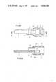
- FIG. 1is an exploded view of the key according to the invention in a practical embodiment
- FIGS. 2a and 2bare top plan and exploded sectional views, respectively, of a first casing shape with one-part key grip for the electronic assembly shown in FIG. 1;
- FIGS. 3a and 3bare top plan and exploded sectional views, respectively, of a second casing shape with a two-part key grip for the electronic assembly shown in FIG. 1;
- FIGS. 4a and 4bare top plan and exploded sectional views, respectively, of a further emobodiment of a casing shape with a two-part key grip, the removable part being constructed as a modular part;
- FIGS. 5a and 5bare top plan and exploded sectional views, respectively, of a further embodiment derived from the shape shown in FIG. 4;
- FIG. 6is a perspective view of an embodiment of the electronic assembly which can be inserted in the casing
- FIG. 7is a perspective view of another embodiment of the electronic assembly.
- FIG. 8is a top plan view of another embodiment of the electronic assembly.
- FIGS. 9a and 9bare top plan and exploded sectional views, respectively, of a further embodiment of a casing shape.
- FIG. 1attempts to show an embodiment which not only makes the features of the invention apparent but also the actual inventive idea. It is certainly contrary to the feelings and efforts of the expert in the field to consider and use his refined product, i.e. the key, as a casing for a novel, additional element.
- the keyis clearly divided up into novel components, which are completely foreign to keys and only when assembly takes place is a flat key of the conventional configuration obtained.
- a casingis obtained which receives the electronics, can be closed or sealed and in this form constitutes a mechanical-electronic flat key and, according to FIG. 1, a reversing key.
- the represented reversing keyhas the typical main elements for such a key, namely the key shank 1 with the depressions 4 which form the mechanical coding, the key grip 2 and a connecting part 12 especially designed for parts 1 and 2, which is always present usually in rudimentary form.
- a marked extension of the connecting part between the grip and the shank and itis shaped so as to fit the contact means 4.
- Contact means 4 with the individual contactsis arranged in an assembly 5 for the electronic coding.
- Assembly 5essentially comprises a circuit board 8 with printed conductors 8A, the contact means 4 and electronic components, in this case an integrated circuit, a chip and further contacts 7A.
- FIG. 6shows the embodiment in the way in which it is used.
- Assembly 5can be inserted in the prepared casing and has the following recesses for this purpose.
- a recess 6Ais formed in connecting part 12 for receiving the contact means 4
- a recess 6Bis formed in the front grip part, i.e. the part closest to the key shank for passing through part of the circuit board 8
- a recess 6Cis formed in the front grip half for receiving the remainder of assembly 5.
- the obviously necessary covers, one at the top and one at the bottomare shown in FIGS. 2a and 2b which shows a casing only.
- Grip 2 in FIG. 1comprises a part 2A fixed to the key shank 1 and a removable, modular part 2B, which can be constructed in numerous different ways.
- part 2Bhas a further recess 6D in which can be placed a power supply in the form of a battery 10, which is in turn connected to contact 7B.
- the modular part 2B of grip 2constitutes a power supply part for assembly 5, which is coupled to the fixed grip part 2A and by means of contact pair 7A/7B energizes the key.
- the modular partis fixed to the grip in a standard precision engineering manner, no details thereof will be given here.
- the splitting up of the key grip 2 into a fixed part 2A and a modular part 2Bconstitutes a special embodiment, which makes it possible e.g. to individualize the key by inserting numbers, marks, etc, to functionally extend the key with further interchangeable functional element and to use the key as a selectable advertising medium, the individual advertisement being applied to the modular part, etc.
- FIGS. 2a, 2b, 3a, 3b, 4a, 4b and 5bshow various casing shapes, while FIGS. 4a and 5a show different modular parts.
- FIG. 2aThe simplest casing configuration is shown in FIG. 2a from above and in section in FIG. 2b from the side.
- the conventional key stop 11Following onto the key shank 1, which naturally does not carry the mechanical coding on manufacture, is provided the conventional key stop 11. This is followed by connecting part 12 with the first recess 6A, in which can be placed the contact means 4.
- the following depression 6Bis in the form of a flat channel for receiving the circuit board 8 of assembly 5, which finally issues into recess 6C, which here takes up the largest part of grip 2, in which is then housed the electronic components, e.g. chip 9. Recess 6C passes through the entire thickness of grip 2, i.e.
- the key/casing blankcan be easily produced, namely by punching, which also applies to the covers.
- the depressions 3 for the mechanical codingare then milled onto the key shank of the blank, the electronic assembly being subsequently fitted.
- the "electronics" of the assemblyis to a certain extent neutral and is programmed for the specific customer prior to use. This is not the case with mechanical coding, which is not easily interchangeable. It is therefore recommended that the mechanical coding be hierarchically placed as low as possible, so that a maximum number of keys of an organisation group are "mechanically identical, but electrically different".
- FIGS. 3a and 3bshow a casing whose recess 6C does not extend through the entire thickness of grip 2. It is made sufficiently thick that there is sufficient space for the assembly and a casing base 30 is retained. This saves manipulation with the lower cover 21, so that the key merely comprises the casing, electronic assembly and cover, said casing also being manufacturable by punching or stamping. Inner edges and shoulders need not be as marked as obtainable, e.g. by milling.
- This casing shapei.e. the casing part with covers and assembly to be housed therein leads to major advantages. If, in accordance with the inventive idea, it is possible to get away from the idea of considering a key and instead of looking upon it as a casing, with a key shank fitted thereto in the manner of a handle, then sudden free mental access is obtained to the stylistic elements of similar casings, such as e.g. watch cases and their closure possibilities. It is obvious that for economic considerations, the solutions adopted there could only rarely be used as such, but when appropriately adapted the measures known therefrom can indeed be transferred.
- FIGS. 4a and 4bAn example of such a case is shown in part in FIGS. 4a and 4b, where a one-sided, non-symmetrically thickened casing with prismatic bevels on the edges gives the appearance of a watch.
- This measure of one-sided thickeninggives sufficient space in the grip recess 6C, in order to be able to house electronic assemblies for the highest demands.
- Recess 6Balso has sufficient space to provide detachable contacts between contact means 4 and assembly 5, so that the latter can be interchanged alone.
- absolute securityis not vital, it is unimportant that the cover 20 can be removed as in the case of a watch.
- FIGS. 4a and 4bagain show the construction of the split grip according to FIG. 1, where there is a fixed part 2A and a modular part 2B.
- This extended casing technologypermits an element interchange, without having to enter the interior of the casing.
- the modular part 2Bis the relatively easily interchangeable support for functional elements or marks.
- Functional elementswould be power supplies, additional assemblies, etc. and marks would be room numbers for hotel keys, advertisements or single carat diamonds as advertising gifts, etc.
- This modular partis then fixed to the stationary grip part 2A by insertion, mounting with a clip or pin or screw attachment.
- FIGS. 1 to 4all relate to reversing keys, so that the contact means 4 is constructed in such a way that it engages around the two narrow sides of the connecting part, but this is obviously not necessary.
- a bit keywhich is actually not a reversing key, can be given the same casing technology, the contacts of a one-sided contact means merely being arranged on the transition part of the key back.
- Assembly 5 in FIG. 1, as already described,comprises a circuit board as a support and a connecting element for the electronic components and the contact means contacting the outside.
- FIG. 6shows it in the embodiment as used.
- a flexible circuit board 8 with corresponding insulating varnishesis used for this construction.
- the electronic component 9is a DIL IC with 16 legs.
- the printed conductors 8Aare formed by etching from the flexprint coating.
- the contact means 4is produced by punching or stamping.
- the necessary connecting web 45is left as a shorting link on the contact means during storage and the fitting of the assembly into the casing and consequently protects the contacted IC against the influences of static electricity. It has also proved unnecessary to insulate the interior of the casing, if the actual assembly is adequately insulated.
- FIG. 7shows a different embodiment of the electronic assembly.
- the contact means 4in this case with four contacts, has the same construction as described hereinbefore.
- the electronic component 9is a silicon wafer with the integrated circuit, a chip. This chip is bonded to the contact means in direct manner with contact wires. A varnish coating can be used between the chip and the means for mechanical damping and electrical insulation.
- the contact meansis placed in the casing in the usual way, chip 9 being housed in recess 6A. The other recesses can either be used for other purposes or can be omitted.
- FIG. 8shows an electronic assembly which can be designed in a very universal manner.
- a substrate Swhich can be a small ceramic plate or a rigid or flexible circuit board of the corresponding size.
- IC 2can be an eight bit processor and the other two IC1 and IC3 can be its periphery which interchange data via means 9A.
- the size of such a processor assemblyfalls within the scope within which electronic components can be housed in a key with the aid of the discussed casing technology.
- the electronic assembly shown in FIG. Astill has not contact means 4. This is soldered onto part 40 and the resulting finished assembly is housed in its casing.
- FIG. 9finally shows a special casing configuration for the discussed electro-mecanical key of which the key grip 2 has a hole or passage 25 for attachment to a ring for a bunch of keys.
- the casingis divided into four parts: a first part comprising the key shank 1 and the portion with the recesses 6A,6B,6C for electrical contact means, circuit carrier with conductors and the electronic components; then a second part which comprises a cover 20 for simultaneously closing recesses 6A and 6B and finally a third and a fourth part forming a double shell cover 20A/20B (e.g. like an oyster).
- the shell coverscan be joined and fixed in known manner e.g. it can be tightly held by clip fastening or glued by metal cement.
- the shell coverscan be made of plastic or any other suitable material so that it can be joined also in a thermal process.
Landscapes
- Engineering & Computer Science (AREA)
- Manufacturing & Machinery (AREA)
- Physics & Mathematics (AREA)
- General Physics & Mathematics (AREA)
- Lock And Its Accessories (AREA)
- Push-Button Switches (AREA)
Abstract
Description
Claims (12)
Applications Claiming Priority (2)
| Application Number | Priority Date | Filing Date | Title |
|---|---|---|---|
| CH1304/84 | 1984-03-15 | ||
| CH1304/84ACH664595A5 (en) | 1984-03-15 | 1984-03-15 | ELECTRONIC-MECHANICAL FLAT KEY. |
Publications (1)
| Publication Number | Publication Date |
|---|---|
| US4686358Atrue US4686358A (en) | 1987-08-11 |
Family
ID=4207302
Family Applications (1)
| Application Number | Title | Priority Date | Filing Date |
|---|---|---|---|
| US06/712,136Expired - Fee RelatedUS4686358A (en) | 1984-03-15 | 1985-03-15 | Programmable electronic-mechanical reversing flat key interactively communicatable with data processing means |
Country Status (22)
| Country | Link |
|---|---|
| US (1) | US4686358A (en) |
| JP (1) | JPS60208572A (en) |
| KR (1) | KR850007117A (en) |
| AT (1) | AT390470B (en) |
| AU (1) | AU579350B2 (en) |
| BE (1) | BE901936A (en) |
| CA (1) | CA1263250A (en) |
| CH (1) | CH664595A5 (en) |
| DE (1) | DE3507871A1 (en) |
| DK (1) | DK159978C (en) |
| ES (3) | ES292870Y (en) |
| FI (1) | FI81875C (en) |
| FR (1) | FR2561292B1 (en) |
| GB (1) | GB2155988B (en) |
| HK (1) | HK100889A (en) |
| IL (1) | IL74411A (en) |
| IT (1) | IT1184728B (en) |
| LU (1) | LU85781A1 (en) |
| NL (1) | NL189047C (en) |
| NO (1) | NO164855C (en) |
| SE (1) | SE459926B (en) |
| ZA (1) | ZA851619B (en) |
Cited By (62)
| Publication number | Priority date | Publication date | Assignee | Title |
|---|---|---|---|---|
| US4771620A (en)* | 1985-12-19 | 1988-09-20 | Bauer Kaba Ag | Locking device for a mechanical-electronic locking apparatus |
| US4789859A (en)* | 1986-03-21 | 1988-12-06 | Emhart Industries, Inc. | Electronic locking system and key therefor |
| US4891636A (en)* | 1987-11-20 | 1990-01-02 | Ncr Corporation | Electronic keylock system |
| US4993627A (en)* | 1989-05-02 | 1991-02-19 | Phelan Michael D | Electronically controlled locking mechanism |
| WO1991018169A1 (en)* | 1990-05-11 | 1991-11-28 | Medeco Security Locks, Inc. | Electronic security system |
| US5117097A (en)* | 1990-02-27 | 1992-05-26 | Kabushiki Kaisha Tokai Rika Denki Seisakusho | Key system for a vehicle |
| US5157244A (en)* | 1989-12-19 | 1992-10-20 | Amp Incorporated | Smart key system |
| US5198643A (en)* | 1991-02-26 | 1993-03-30 | Computerized Security Systems, Inc. | Adaptable electronic key and lock system |
| US5311757A (en)* | 1992-03-06 | 1994-05-17 | Aug. Winkhaus Gmbh & Co. Kg | Flat key with circuit chip |
| US5367295A (en)* | 1992-02-14 | 1994-11-22 | Security People, Inc. | Conventional mechanical lock cylinders and keys with electronic access control feature |
| US5423198A (en)* | 1993-11-12 | 1995-06-13 | Kaba High Security Locks, Inc. | Dual control mode lock |
| US5481253A (en)* | 1992-02-18 | 1996-01-02 | Phelan; Michael D. | Automotive security system |
| US5552777A (en)* | 1992-02-14 | 1996-09-03 | Security People, Inc. | Mechanical/electronic lock and key |
| US5677568A (en)* | 1991-12-26 | 1997-10-14 | Mitsubishi Denki Kabushiki Kaisha | Thin IC card |
| US5727408A (en)* | 1994-11-14 | 1998-03-17 | Kabushiki Kaisha Tokai Rika Denki Seisakusho | Signal processing device with magnetism antenna and key device with the signal processing device |
| US5745044A (en)* | 1990-05-11 | 1998-04-28 | Medeco Security Locks, Inc. | Electronic security system |
| US5771722A (en)* | 1993-11-12 | 1998-06-30 | Kaba High Security Locks Corporation | Dual control mode lock system |
| US5775148A (en)* | 1995-03-16 | 1998-07-07 | Medeco Security Locks, Inc. | Universal apparatus for use with electronic and/or mechanical access control devices |
| US6000609A (en)* | 1997-12-22 | 1999-12-14 | Security People, Inc. | Mechanical/electronic lock and key therefor |
| US6005487A (en)* | 1990-05-11 | 1999-12-21 | Medeco Security Locks, Inc. | Electronic security system with novel electronic T-handle lock |
| US6102288A (en)* | 1993-06-04 | 2000-08-15 | Vendoret Holding S. A. | Card for a pledge lock |
| EP0713944A4 (en)* | 1994-05-20 | 2000-10-11 | Tokai Rika Co Ltd | Key provided with built-in transmitter element |
| EP0846822A3 (en)* | 1996-12-03 | 2001-02-28 | Bayerische Motoren Werke Aktiengesellschaft, Patentabteilung AJ-3 | Individual data storage memory for positioning equipment parts of a vehicle |
| KR20010083975A (en)* | 2000-02-23 | 2001-09-06 | 서석호 | Hybrid key system |
| US6442986B1 (en) | 1998-04-07 | 2002-09-03 | Best Lock Corporation | Electronic token and lock core |
| US6552650B1 (en) | 1992-02-14 | 2003-04-22 | Asil T. Gokcebay | Coin collection lock and key |
| US6564601B2 (en) | 1995-09-29 | 2003-05-20 | Hyatt Jr Richard G | Electromechanical cylinder plug |
| EP1363249A1 (en)* | 2002-05-15 | 2003-11-19 | Teleco Automation S.R.L. | Vehicle key with multi-user remote control |
| US20040035160A1 (en)* | 2002-02-22 | 2004-02-26 | Glenn Meekma | Radio frequency electronic lock |
| WO2004070664A1 (en)* | 2003-02-06 | 2004-08-19 | Nagracard Sa | Method for making a security module designed in particular for controlling access and security module obtained by said method |
| ES2214952A1 (en)* | 2002-11-08 | 2004-09-16 | Bolt Gestion Y Patrimonio, S.L. | Security box for use in e.g. telephone booth to store collection of coins, has box body whose door opening part is provided with terminals, and power source connected with key generator power circuit that is connected to door opening system |
| US20060226240A1 (en)* | 2005-04-06 | 2006-10-12 | Innovatier, Inc. | Smart card and method for manufacturing a smart card |
| US20060230796A1 (en)* | 2003-01-17 | 2006-10-19 | Keso Ag | Electronic locking device and safety key |
| US20070012771A1 (en)* | 2005-07-15 | 2007-01-18 | Innovatier, Inc. | RFID bracelet and method for manufacturing a RFID bracelet |
| US20070235548A1 (en)* | 2006-04-10 | 2007-10-11 | Innovatier, Inc. | Electronic inlay module used for electronic cards and tags |
| US20070290048A1 (en)* | 2006-06-20 | 2007-12-20 | Innovatier, Inc. | Embedded electronic device and method for manufacturing an embedded electronic device |
| US20070290863A1 (en)* | 1992-08-12 | 2007-12-20 | Tuttle John R | Radio Frequency Identification Device And Method |
| US20070290862A1 (en)* | 1997-08-20 | 2007-12-20 | Tuttle Mark E | Electronic Communication Devices, Methods Of Forming Electrical Communication Devices, And Communications Methods |
| CN100362204C (en)* | 2004-03-30 | 2008-01-16 | 罗晓晖 | Rotating disk managed anti-peep keying-in cipher key |
| US20080055824A1 (en)* | 2006-08-25 | 2008-03-06 | Innovatier, Inc. | Battery powered device having a protective frame |
| US20080160397A1 (en)* | 2006-08-25 | 2008-07-03 | Innovatier, Inc | Battery powered device having a protective frame |
| US20080237356A1 (en)* | 2007-03-23 | 2008-10-02 | Innovatier, Inc. | Step card and method for making a step card |
| US20080282540A1 (en)* | 2007-05-14 | 2008-11-20 | Innovatier, Inc. | Method for making advanced smart cards with integrated electronics using isotropic thermoset adhesive materials with high quality exterior surfaces |
| US20090025440A1 (en)* | 2007-07-29 | 2009-01-29 | Downing Bart M | Lock and Key |
| US20090064746A1 (en)* | 2007-09-08 | 2009-03-12 | Nima Bigdely Shamlo | Method, apparatus, and system for an electronic key usage history indicator |
| US20090085717A1 (en)* | 2007-09-27 | 2009-04-02 | Gregory Paul Kirkjan | Energy-efficient electronic access control |
| US20090096614A1 (en)* | 2007-10-15 | 2009-04-16 | Innovatier, Inc. | Rfid power bracelet and method for manufacturing a rfid power bracelet |
| US20090181215A1 (en)* | 2008-01-15 | 2009-07-16 | Innovatier, Inc. | Plastic card and method for making a plastic card |
| US20100246146A1 (en)* | 2009-03-25 | 2010-09-30 | Denso Corporation | Electronic device and method of producing the same |
| US20110040478A1 (en)* | 2009-08-14 | 2011-02-17 | Harman Becker Automotive Systems Gmbh | Navigation update system for a vehicle |
| US20110073509A1 (en)* | 2009-09-30 | 2011-03-31 | Palmer David H | Oblong object holder |
| US20110073498A1 (en)* | 2009-09-30 | 2011-03-31 | Palmer David H | Oblong object holder |
| US20110073499A1 (en)* | 2009-09-30 | 2011-03-31 | Palmer David H | Oblong object holder |
| USRE42773E1 (en)* | 1992-06-17 | 2011-10-04 | Round Rock Research, Llc | Method of manufacturing an enclosed transceiver |
| US8528373B2 (en) | 1997-06-06 | 2013-09-10 | Richard G. Hyatt, Jr. | Electronic cam assembly |
| CN103745517A (en)* | 2014-01-20 | 2014-04-23 | 萧进宏 | Key with key password and intelligent lockset matched with key |
| US8922333B1 (en) | 2013-09-10 | 2014-12-30 | Gregory Paul Kirkjan | Contactless electronic access control system |
| USD742202S1 (en)* | 2014-09-11 | 2015-11-03 | Thomas Jason Cyphers | Sign frame key |
| US9605446B2 (en) | 2013-10-13 | 2017-03-28 | Lior Shabtay | Portable electronic device integrated with a key |
| US9704316B2 (en) | 2013-09-10 | 2017-07-11 | Gregory Paul Kirkjan | Contactless electronic access control system |
| US20180005499A1 (en)* | 2009-01-13 | 2018-01-04 | Invue Security Products Inc. | Combination non-programmable and programmable key for security device |
| US11574513B2 (en) | 2020-03-31 | 2023-02-07 | Lockfob, Llc | Electronic access control |
Families Citing this family (55)
| Publication number | Priority date | Publication date | Assignee | Title |
|---|---|---|---|---|
| DE3509579A1 (en)* | 1985-03-16 | 1986-09-18 | Vdo Adolf Schindling Ag, 6000 Frankfurt | IGNITION KEY WITH TRANSMITTER |
| GB8528444D0 (en)* | 1985-11-19 | 1985-12-24 | Taylor J W | Key for locks |
| FR2590616B1 (en)* | 1985-11-22 | 1990-10-19 | Michot Gerard | MECANO-ELECTRONIC KEY LOCK. |
| DE3583614D1 (en)* | 1985-12-03 | 1991-08-29 | Fuss Fritz Gmbh & Co | LOCKING DEVICE WITH ELECTRONIC IDENTIFICATION SYSTEM. |
| DE3602989A1 (en)* | 1986-01-31 | 1987-11-19 | Herz Gmbh | ELECTROMECHANICAL LOCKING SYSTEM |
| DE3606620A1 (en)* | 1986-02-28 | 1987-09-03 | Winkhaus Fa August | ELECTRONIC DOOR LOCK |
| EP0334396A3 (en)* | 1986-02-28 | 1990-06-20 | Aug. Winkhaus GmbH & Co. KG | Locking device |
| FR2597913A1 (en)* | 1986-04-24 | 1987-10-30 | Beaurepaire Patrick De | Standardised electronic lock and key system with a double programmable memory and self contained electrical supply |
| FR2598037B1 (en)* | 1986-04-24 | 1988-11-25 | Connexion Ste Nle | ELECTRICAL CONNECTOR FOR VALIDATION INDICATOR |
| DE3627493A1 (en)* | 1986-08-13 | 1988-02-25 | Yannikos Sibylle | Key with a code |
| JPH07122358B2 (en)* | 1986-09-04 | 1995-12-25 | 株式会社ゼネラルリサ−チオブエレクトロニツクス | Key device |
| CH671840A5 (en)* | 1986-09-25 | 1989-09-29 | Microtronic Ag | |
| JPS6364856U (en)* | 1986-10-16 | 1988-04-28 | ||
| EP0267429B1 (en)* | 1986-10-20 | 1991-05-08 | Siemens Aktiengesellschaft | Transmitter for a remotely controlled locking device for an automotive vehicle |
| JPH0721264B2 (en)* | 1986-10-21 | 1995-03-08 | 日本電装株式会社 | Wireless door lock controller |
| CH672653A5 (en)* | 1987-02-09 | 1989-12-15 | Berchtold Ag | |
| US4823575A (en)* | 1987-09-28 | 1989-04-25 | Bauer Kaba Ag | Cylinder lock and key |
| JPH0718280B2 (en)* | 1987-10-27 | 1995-03-01 | 本田技研工業株式会社 | Key device |
| ES2010274A6 (en)* | 1988-06-01 | 1989-11-01 | Talleres Escoriaza Sa | Electronic locking device |
| JPH0613967Y2 (en)* | 1988-08-22 | 1994-04-13 | シロキ工業株式会社 | Illuminated key plate |
| FR2635809B1 (en)* | 1988-08-24 | 1990-11-23 | Samokine Georges | SYSTEM FOR EXCHANGING INFORMATION BETWEEN A PORTABLE OBJECT SUCH AS A KEY, AND AN EXCHANGE DEVICE |
| EP0401541A1 (en)* | 1989-05-15 | 1990-12-12 | Masaji Terada | Key having a gripping portion made of synthetic resin |
| DE3918445C1 (en)* | 1989-06-06 | 1990-12-20 | Anatoli Dipl.-Ing. 3013 Barsinghausen De Stobbe | |
| KR910006587A (en)* | 1989-09-11 | 1991-04-29 | 배효경 | Lighting |
| FR2655368A1 (en)* | 1989-12-05 | 1991-06-07 | Vachette Sa | Device for contact(s) between a mechanical and electronic key and a mechanical and electronic lock, lock, cylinder plug and key thus equipped |
| DE8915242U1 (en)* | 1989-12-22 | 1990-04-05 | Ikon AG Präzisionstechnik, 1000 Berlin | Lock-key combination |
| US5099665A (en)* | 1989-12-30 | 1992-03-31 | Masaji Terada | Key having a gripping portion made of synthetic resin |
| US4998952A (en)* | 1990-03-02 | 1991-03-12 | Medeco Security Locks, Inc. | Key for electronic and mechanical locks |
| WO1991014065A1 (en)* | 1990-03-07 | 1991-09-19 | Siegfried Sikora | Lock unit for a motor vehicle with remote-controlled door lock |
| JPH0738597Y2 (en)* | 1990-04-27 | 1995-09-06 | 株式会社アルファ | Electronic key device |
| IL96262A (en)* | 1990-11-06 | 1994-02-27 | Mul T Lock Ltd | Vehicle anti-theft system |
| JP2568469B2 (en)* | 1992-02-25 | 1997-01-08 | 株式会社イトーキ | Safe box system |
| CH685444A5 (en)* | 1991-10-07 | 1995-07-14 | Bauer Kaba Ag | Identification carrier for a locking system. |
| GB2261254A (en)* | 1991-11-09 | 1993-05-12 | Christopher Stafford | Electronically reprogrammable key and lock |
| FR2687427A1 (en)* | 1992-02-18 | 1993-08-20 | Bricard Sa | Latching assembly for a lock consisting of a cylinder with electromagnetic actuation and of a key with electronic coding, as well as key belonging to this assembly |
| DE4207161A1 (en)* | 1992-03-06 | 1993-09-09 | Winkhaus Fa August | ELECTRONIC LOCKING CYLINDER |
| FR2694327B1 (en)* | 1992-08-03 | 1994-09-23 | Valeo Securite Habitacle | Key-transmitter assembly for the remote control of certain functions of a motor vehicle. |
| IT1268468B1 (en)* | 1993-02-11 | 1997-03-04 | Gemini Elettronica | ASSEMBLY OF AN ALARM REMOTE CONTROL AND A CAR IGNITION KEY |
| FR2705116B1 (en)* | 1993-05-11 | 1995-08-04 | Peronnet Patrick | DIGITAL ELECTRONIC LOCK. |
| DE4315892C2 (en)* | 1993-05-12 | 1995-06-08 | Wehl Hans Joseph | Locking system for indicating keys |
| US5433096A (en)* | 1993-08-26 | 1995-07-18 | Strattec Security Corporation | Key assembly for vehicle ignition locks |
| US6035677A (en)* | 1993-08-26 | 2000-03-14 | Strattec Security Corporation | Key assembly for vehicle ignition locks |
| US6427504B1 (en) | 1993-08-26 | 2002-08-06 | Strattec Security Corporation | Key assembly for vehicle ignition locks |
| ES2116836B1 (en)* | 1994-05-12 | 1999-02-16 | Valeo Sistemas De Seguridad S | DEVICE FOR THE INSERTION OF AN ELECTRONIC COMPONENT IN THE KEY OF A VEHICLE, AND A KEY PROVIDED WITH SUCH DEVICE. |
| GB9413532D0 (en)* | 1994-07-05 | 1994-08-24 | Systemteq Limited | Electronic locks |
| DE9412174U1 (en)* | 1994-07-21 | 1994-11-24 | Schaeffer Apparatebau KG, 14169 Berlin | Locking system, especially for securing doors |
| US5819564A (en)* | 1994-12-01 | 1998-10-13 | Nissan Motor Co., Ltd. | Key plate structure for automobile |
| DE19518957C1 (en)* | 1995-05-23 | 1996-11-21 | Leicher Gmbh & Co | Safety deposit box operating system |
| ATE249565T1 (en)* | 1998-06-02 | 2003-09-15 | Omega Electronics Sa | ELECTRONIC DEVICE, IN PARTICULAR ELECTRONIC KEY |
| KR20030047198A (en)* | 2001-12-08 | 2003-06-18 | 현대자동차주식회사 | Charging system for transmitter of vehicle |
| DE10360949B4 (en)* | 2003-12-23 | 2020-03-26 | Günter Uhlmann | Electromechanical locking system |
| SE528602C2 (en)* | 2005-06-10 | 2006-12-27 | Assa Ab | Key and way of producing such key |
| FR2936636B1 (en)* | 2008-10-01 | 2014-04-25 | Valeo Securite Habitacle | IDENTIFICATION MODULE FOR MOTOR VEHICLE. |
| JP2012144879A (en)* | 2011-01-11 | 2012-08-02 | Alps Electric Co Ltd | Portable machine |
| CN107052796B (en)* | 2017-06-06 | 2018-10-26 | 浙江捷博智能科技有限公司 | A kind of electronic password lock assembly technology based on intelligent identifying system |
Citations (3)
| Publication number | Priority date | Publication date | Assignee | Title |
|---|---|---|---|---|
| US4200227A (en)* | 1978-12-26 | 1980-04-29 | Lemelson Jerome H | Key assembly for electronic system |
| US4271352A (en)* | 1979-05-07 | 1981-06-02 | Thomas Lon G | Lost personal accessory return method and article |
| US4578573A (en)* | 1983-03-23 | 1986-03-25 | Datakey, Inc. | Portable electronic information devices and method of manufacture |
Family Cites Families (11)
| Publication number | Priority date | Publication date | Assignee | Title |
|---|---|---|---|---|
| GB481545A (en)* | 1937-03-11 | 1938-03-14 | Cyril James Gowland | Watch combined with latch-key |
| CH392313A (en)* | 1962-04-02 | 1965-05-15 | Roger Manzardo Scipione | Recognition means for keys |
| US3347072A (en)* | 1965-06-28 | 1967-10-17 | Bretan H | Electronic solid state lock mechanism |
| AT320466B (en)* | 1972-06-29 | 1975-02-10 | Kibolac Handels Ges M B H | Lock |
| DE2325566B2 (en)* | 1973-05-19 | 1981-06-04 | Zeiss Ikon Ag Goerz-Werk, 1000 Berlin | Magnetically / mechanically working lock cylinder |
| JPS5539708A (en)* | 1978-09-12 | 1980-03-19 | Gunei Kagaku Kogyo Kk | Method of extracting starch from corn |
| US4297569A (en)* | 1979-06-28 | 1981-10-27 | Datakey, Inc. | Microelectronic memory key with receptacle and systems therefor |
| FR2503425A1 (en)* | 1981-04-03 | 1982-10-08 | Barbier Jacques | Electronic security system for vehicle ignition key - contains memory and processor to store data from processing circuit on vehicle with data transferred key circuit and transfer ring on lock |
| US4420794A (en)* | 1981-09-10 | 1983-12-13 | Research, Incorporated | Integrated circuit switch |
| DE3245681C2 (en)* | 1982-01-16 | 1986-02-13 | BKS Sicherheitstechnik GmbH, 5040 Brühl | Non-mechanically / mechanically coded key with a lock cylinder to be operated |
| DE3205586C2 (en)* | 1982-02-17 | 1985-10-03 | Doduco KG Dr. Eugen Dürrwächter, 7530 Pforzheim | Electromechanical locking device for magnetic keys |
- 1984
- 1984-03-15CHCH1304/84Apatent/CH664595A5/ennot_activeIP Right Cessation
- 1985
- 1985-02-21ILIL74411Apatent/IL74411A/ennot_activeIP Right Cessation
- 1985-02-21ATAT0051985Apatent/AT390470B/enactiveIP Right Maintenance
- 1985-02-22GBGB08504619Apatent/GB2155988B/ennot_activeExpired
- 1985-02-22LULU85781Apatent/LU85781A1/enunknown
- 1985-02-25AUAU39121/85Apatent/AU579350B2/ennot_activeCeased
- 1985-03-04ZAZA851619Apatent/ZA851619B/enunknown
- 1985-03-06DEDE19853507871patent/DE3507871A1/enactiveGranted
- 1985-03-08JPJP60044971Apatent/JPS60208572A/enactiveGranted
- 1985-03-11NLNLAANVRAGE8500686,Apatent/NL189047C/ennot_activeIP Right Cessation
- 1985-03-14NONO851013Apatent/NO164855C/enunknown
- 1985-03-14FRFR8503783Apatent/FR2561292B1/ennot_activeExpired
- 1985-03-14BEBE0/214647Apatent/BE901936A/ennot_activeIP Right Cessation
- 1985-03-14SESE8501260Apatent/SE459926B/ennot_activeIP Right Cessation
- 1985-03-14ESES1985292870Upatent/ES292870Y/ennot_activeExpired - Lifetime
- 1985-03-14ITIT19906/85Apatent/IT1184728B/enactive
- 1985-03-14CACA000476532Apatent/CA1263250A/ennot_activeExpired
- 1985-03-14DKDK117285Apatent/DK159978C/ennot_activeApplication Discontinuation
- 1985-03-14FIFI851023Apatent/FI81875C/ennot_activeIP Right Cessation
- 1985-03-15USUS06/712,136patent/US4686358A/ennot_activeExpired - Fee Related
- 1985-03-15KRKR1019850001684Apatent/KR850007117A/ennot_activeCeased
- 1986
- 1986-09-03ESES1986295648Upatent/ES295648Y/ennot_activeExpired
- 1986-09-03ESES1986295649Upatent/ES295649Y/ennot_activeExpired
- 1989
- 1989-12-21HKHK1008/89Apatent/HK100889A/ennot_activeIP Right Cessation
Patent Citations (3)
| Publication number | Priority date | Publication date | Assignee | Title |
|---|---|---|---|---|
| US4200227A (en)* | 1978-12-26 | 1980-04-29 | Lemelson Jerome H | Key assembly for electronic system |
| US4271352A (en)* | 1979-05-07 | 1981-06-02 | Thomas Lon G | Lost personal accessory return method and article |
| US4578573A (en)* | 1983-03-23 | 1986-03-25 | Datakey, Inc. | Portable electronic information devices and method of manufacture |
Cited By (98)
| Publication number | Priority date | Publication date | Assignee | Title |
|---|---|---|---|---|
| US4771620A (en)* | 1985-12-19 | 1988-09-20 | Bauer Kaba Ag | Locking device for a mechanical-electronic locking apparatus |
| US4789859A (en)* | 1986-03-21 | 1988-12-06 | Emhart Industries, Inc. | Electronic locking system and key therefor |
| US4891636A (en)* | 1987-11-20 | 1990-01-02 | Ncr Corporation | Electronic keylock system |
| US4993627A (en)* | 1989-05-02 | 1991-02-19 | Phelan Michael D | Electronically controlled locking mechanism |
| US5157244A (en)* | 1989-12-19 | 1992-10-20 | Amp Incorporated | Smart key system |
| US5321247A (en)* | 1989-12-19 | 1994-06-14 | The Whitaker Corporation | System for handling variable digital information |
| US5117097A (en)* | 1990-02-27 | 1992-05-26 | Kabushiki Kaisha Tokai Rika Denki Seisakusho | Key system for a vehicle |
| US5745044A (en)* | 1990-05-11 | 1998-04-28 | Medeco Security Locks, Inc. | Electronic security system |
| WO1991018169A1 (en)* | 1990-05-11 | 1991-11-28 | Medeco Security Locks, Inc. | Electronic security system |
| US5140317A (en)* | 1990-05-11 | 1992-08-18 | Medeco Security Locks, Inc. | Electronic security system |
| US6005487A (en)* | 1990-05-11 | 1999-12-21 | Medeco Security Locks, Inc. | Electronic security system with novel electronic T-handle lock |
| US5198643A (en)* | 1991-02-26 | 1993-03-30 | Computerized Security Systems, Inc. | Adaptable electronic key and lock system |
| US5677568A (en)* | 1991-12-26 | 1997-10-14 | Mitsubishi Denki Kabushiki Kaisha | Thin IC card |
| US7397343B1 (en)* | 1992-02-14 | 2008-07-08 | Security People, Inc. | Conventional mechanical lock cylinders and keys with electronic access control feature |
| US5552777A (en)* | 1992-02-14 | 1996-09-03 | Security People, Inc. | Mechanical/electronic lock and key |
| US6552650B1 (en) | 1992-02-14 | 2003-04-22 | Asil T. Gokcebay | Coin collection lock and key |
| US5367295A (en)* | 1992-02-14 | 1994-11-22 | Security People, Inc. | Conventional mechanical lock cylinders and keys with electronic access control feature |
| US6927670B1 (en) | 1992-02-14 | 2005-08-09 | Security People, Inc. | Conventional mechanical lock cylinders and keys with electronic access control feature |
| US5481253A (en)* | 1992-02-18 | 1996-01-02 | Phelan; Michael D. | Automotive security system |
| US5311757A (en)* | 1992-03-06 | 1994-05-17 | Aug. Winkhaus Gmbh & Co. Kg | Flat key with circuit chip |
| USRE42773E1 (en)* | 1992-06-17 | 2011-10-04 | Round Rock Research, Llc | Method of manufacturing an enclosed transceiver |
| US20070290863A1 (en)* | 1992-08-12 | 2007-12-20 | Tuttle John R | Radio Frequency Identification Device And Method |
| US7583192B2 (en) | 1992-08-12 | 2009-09-01 | Keystone Technology Solutions, Llc | Radio frequency identification device and method |
| US7746230B2 (en) | 1992-08-12 | 2010-06-29 | Round Rock Research, Llc | Radio frequency identification device and method |
| US8018340B2 (en) | 1992-08-12 | 2011-09-13 | Round Rock Research, Llc | System and method to track articles at a point of origin and at a point of destination using RFID |
| US6102288A (en)* | 1993-06-04 | 2000-08-15 | Vendoret Holding S. A. | Card for a pledge lock |
| US5771722A (en)* | 1993-11-12 | 1998-06-30 | Kaba High Security Locks Corporation | Dual control mode lock system |
| US5423198A (en)* | 1993-11-12 | 1995-06-13 | Kaba High Security Locks, Inc. | Dual control mode lock |
| EP0713944A4 (en)* | 1994-05-20 | 2000-10-11 | Tokai Rika Co Ltd | Key provided with built-in transmitter element |
| US5727408A (en)* | 1994-11-14 | 1998-03-17 | Kabushiki Kaisha Tokai Rika Denki Seisakusho | Signal processing device with magnetism antenna and key device with the signal processing device |
| US5775148A (en)* | 1995-03-16 | 1998-07-07 | Medeco Security Locks, Inc. | Universal apparatus for use with electronic and/or mechanical access control devices |
| US6564601B2 (en) | 1995-09-29 | 2003-05-20 | Hyatt Jr Richard G | Electromechanical cylinder plug |
| US20030205071A1 (en)* | 1995-09-29 | 2003-11-06 | Hyatt Richard G. | Electromechanical cylinder plug |
| US8122746B2 (en) | 1995-09-29 | 2012-02-28 | Hyatt Jr Richard G | Electromechanical cylinder plug |
| US8141399B2 (en) | 1995-09-29 | 2012-03-27 | Hyatt Jr Richard G | Electromechanical cylinder plug |
| US20070289346A1 (en)* | 1995-09-29 | 2007-12-20 | Hyatt Richard G Jr | Electromechanical cylinder plug |
| EP0846822A3 (en)* | 1996-12-03 | 2001-02-28 | Bayerische Motoren Werke Aktiengesellschaft, Patentabteilung AJ-3 | Individual data storage memory for positioning equipment parts of a vehicle |
| US8528373B2 (en) | 1997-06-06 | 2013-09-10 | Richard G. Hyatt, Jr. | Electronic cam assembly |
| US7948382B2 (en) | 1997-08-20 | 2011-05-24 | Round Rock Research, Llc | Electronic communication devices, methods of forming electrical communication devices, and communications methods |
| US7839285B2 (en) | 1997-08-20 | 2010-11-23 | Round Rock Resarch, LLC | Electronic communication devices, methods of forming electrical communication devices, and communications methods |
| US20070290862A1 (en)* | 1997-08-20 | 2007-12-20 | Tuttle Mark E | Electronic Communication Devices, Methods Of Forming Electrical Communication Devices, And Communications Methods |
| US6000609A (en)* | 1997-12-22 | 1999-12-14 | Security People, Inc. | Mechanical/electronic lock and key therefor |
| US7316140B2 (en) | 1998-04-07 | 2008-01-08 | Stanley Security Solutions, Inc. | Electronic token and lock core |
| US6668606B1 (en) | 1998-04-07 | 2003-12-30 | Best Access Systems | Electronic token lock core |
| US6442986B1 (en) | 1998-04-07 | 2002-09-03 | Best Lock Corporation | Electronic token and lock core |
| US6840072B2 (en) | 1998-04-07 | 2005-01-11 | Stanley Security Solutions, Inc. | Electronic token and lock core |
| KR20010083975A (en)* | 2000-02-23 | 2001-09-06 | 서석호 | Hybrid key system |
| US7334443B2 (en) | 2002-02-22 | 2008-02-26 | Master Lock Company Llc | Radio frequency electronic lock |
| US20040035160A1 (en)* | 2002-02-22 | 2004-02-26 | Glenn Meekma | Radio frequency electronic lock |
| EP1363249A1 (en)* | 2002-05-15 | 2003-11-19 | Teleco Automation S.R.L. | Vehicle key with multi-user remote control |
| ES2214952B1 (en)* | 2002-11-08 | 2005-12-01 | Bolt Gestion Y Patrimonio, S.L. | SECURITY CHEST. |
| ES2214952A1 (en)* | 2002-11-08 | 2004-09-16 | Bolt Gestion Y Patrimonio, S.L. | Security box for use in e.g. telephone booth to store collection of coins, has box body whose door opening part is provided with terminals, and power source connected with key generator power circuit that is connected to door opening system |
| US20060230796A1 (en)* | 2003-01-17 | 2006-10-19 | Keso Ag | Electronic locking device and safety key |
| WO2004070664A1 (en)* | 2003-02-06 | 2004-08-19 | Nagracard Sa | Method for making a security module designed in particular for controlling access and security module obtained by said method |
| CN100362204C (en)* | 2004-03-30 | 2008-01-16 | 罗晓晖 | Rotating disk managed anti-peep keying-in cipher key |
| US7237724B2 (en)* | 2005-04-06 | 2007-07-03 | Robert Singleton | Smart card and method for manufacturing a smart card |
| US20060226240A1 (en)* | 2005-04-06 | 2006-10-12 | Innovatier, Inc. | Smart card and method for manufacturing a smart card |
| US20070012771A1 (en)* | 2005-07-15 | 2007-01-18 | Innovatier, Inc. | RFID bracelet and method for manufacturing a RFID bracelet |
| US7607249B2 (en) | 2005-07-15 | 2009-10-27 | Innovatier Inc. | RFID bracelet and method for manufacturing a RFID bracelet |
| US20070235548A1 (en)* | 2006-04-10 | 2007-10-11 | Innovatier, Inc. | Electronic inlay module used for electronic cards and tags |
| US7959085B2 (en) | 2006-04-10 | 2011-06-14 | Innovatier, Inc. | Electronic inlay module used for electronic cards and tags |
| US20070290048A1 (en)* | 2006-06-20 | 2007-12-20 | Innovatier, Inc. | Embedded electronic device and method for manufacturing an embedded electronic device |
| US8727224B2 (en) | 2006-06-20 | 2014-05-20 | Innovatier, Inc. | Embedded electronic device and method for manufacturing an embedded electronic device |
| US20080160397A1 (en)* | 2006-08-25 | 2008-07-03 | Innovatier, Inc | Battery powered device having a protective frame |
| US20080055824A1 (en)* | 2006-08-25 | 2008-03-06 | Innovatier, Inc. | Battery powered device having a protective frame |
| US20080237356A1 (en)* | 2007-03-23 | 2008-10-02 | Innovatier, Inc. | Step card and method for making a step card |
| US20080282540A1 (en)* | 2007-05-14 | 2008-11-20 | Innovatier, Inc. | Method for making advanced smart cards with integrated electronics using isotropic thermoset adhesive materials with high quality exterior surfaces |
| US20090025440A1 (en)* | 2007-07-29 | 2009-01-29 | Downing Bart M | Lock and Key |
| US20090064746A1 (en)* | 2007-09-08 | 2009-03-12 | Nima Bigdely Shamlo | Method, apparatus, and system for an electronic key usage history indicator |
| US8085125B2 (en)* | 2007-09-08 | 2011-12-27 | Nima Bigdely-Shamlo | Method, apparatus, and system for an electronic key usage history indicator |
| US20090085717A1 (en)* | 2007-09-27 | 2009-04-02 | Gregory Paul Kirkjan | Energy-efficient electronic access control |
| US8035477B2 (en) | 2007-09-27 | 2011-10-11 | Gregory Paul Kirkjan | Energy-efficient electronic access control |
| US8339239B2 (en) | 2007-09-27 | 2012-12-25 | Gregory Paul Kirkjan | Electronic access control systems and methods |
| US20090096614A1 (en)* | 2007-10-15 | 2009-04-16 | Innovatier, Inc. | Rfid power bracelet and method for manufacturing a rfid power bracelet |
| US20090181215A1 (en)* | 2008-01-15 | 2009-07-16 | Innovatier, Inc. | Plastic card and method for making a plastic card |
| US20180005499A1 (en)* | 2009-01-13 | 2018-01-04 | Invue Security Products Inc. | Combination non-programmable and programmable key for security device |
| US10490038B2 (en)* | 2009-01-13 | 2019-11-26 | Invue Security Products Inc. | Combination non-programmable and programmable key for security device |
| US8097816B2 (en)* | 2009-03-25 | 2012-01-17 | Denso Corporation | Electronic device and method of producing the same |
| US20100246146A1 (en)* | 2009-03-25 | 2010-09-30 | Denso Corporation | Electronic device and method of producing the same |
| US8744751B2 (en)* | 2009-08-14 | 2014-06-03 | Harman Becker Automotive Systems, Gmbh | Navigation update system for a vehicle |
| US20110040478A1 (en)* | 2009-08-14 | 2011-02-17 | Harman Becker Automotive Systems Gmbh | Navigation update system for a vehicle |
| US8418843B2 (en) | 2009-09-30 | 2013-04-16 | David H. Palmer | Oblong object holder |
| US20110073498A1 (en)* | 2009-09-30 | 2011-03-31 | Palmer David H | Oblong object holder |
| US8322523B2 (en) | 2009-09-30 | 2012-12-04 | Palmer David H | Oblong object holder |
| US20110073499A1 (en)* | 2009-09-30 | 2011-03-31 | Palmer David H | Oblong object holder |
| US20110073509A1 (en)* | 2009-09-30 | 2011-03-31 | Palmer David H | Oblong object holder |
| US11804084B2 (en) | 2013-09-10 | 2023-10-31 | Lockfob, Llc | Contactless electronic access control system |
| US9704316B2 (en) | 2013-09-10 | 2017-07-11 | Gregory Paul Kirkjan | Contactless electronic access control system |
| US10482697B2 (en) | 2013-09-10 | 2019-11-19 | Gregory Paul Kirkjan | Contactless electronic access control system |
| US8922333B1 (en) | 2013-09-10 | 2014-12-30 | Gregory Paul Kirkjan | Contactless electronic access control system |
| US11080951B2 (en) | 2013-09-10 | 2021-08-03 | Lockfob, Llc | Contactless electronic access control system |
| US12211328B2 (en) | 2013-09-10 | 2025-01-28 | Lockfob, Llc | Contactless electronic access control system |
| US9605446B2 (en) | 2013-10-13 | 2017-03-28 | Lior Shabtay | Portable electronic device integrated with a key |
| CN103745517A (en)* | 2014-01-20 | 2014-04-23 | 萧进宏 | Key with key password and intelligent lockset matched with key |
| USD742202S1 (en)* | 2014-09-11 | 2015-11-03 | Thomas Jason Cyphers | Sign frame key |
| US11574513B2 (en) | 2020-03-31 | 2023-02-07 | Lockfob, Llc | Electronic access control |
| US12027001B2 (en) | 2020-03-31 | 2024-07-02 | Lockfob, Llc | Electronic access control |
| US12430966B2 (en) | 2020-03-31 | 2025-09-30 | Lockfob, Llc | Electronic access control |
Also Published As
Similar Documents
| Publication | Publication Date | Title |
|---|---|---|
| US4686358A (en) | Programmable electronic-mechanical reversing flat key interactively communicatable with data processing means | |
| US6927670B1 (en) | Conventional mechanical lock cylinders and keys with electronic access control feature | |
| US5878611A (en) | Flat key | |
| EP0388997A1 (en) | Electronic locking system | |
| US5559370A (en) | Electronic label and carriers therefor | |
| FR2723228B1 (en) | IMPROVED GAME TOKEN | |
| NO963192L (en) | Eurocylinder type design for electronic lock and key system | |
| US4390758A (en) | Key-actuated electrical lock | |
| EP0281277A2 (en) | Improved receptacle device | |
| MY120619A (en) | Portable smart card reader assembly | |
| AU2507997A (en) | Electronic card for electromagnectic data exchange and a process for manufacturing such a card | |
| EP1201852A3 (en) | Lock cylinder with a bridge element for connecting stator parts | |
| JPH05263555A (en) | Identification carrier for lock system | |
| US6231130B1 (en) | Wheel support device | |
| JPH0455730U (en) | ||
| CN209556586U (en) | A kind of portable multi-function key | |
| CN211369817U (en) | Iris lock | |
| JPS63184272A (en) | Modular adaptor | |
| JP3073466U (en) | Connector with cam device | |
| JP4236975B2 (en) | Non-contact information recording medium | |
| JPS6336772Y2 (en) | ||
| JPS6012057Y2 (en) | electronic lock key | |
| KR200200986Y1 (en) | Time capsule assembly | |
| IT9003722A1 (en) | METHOD FOR THE CONSTRUCTION OF AN ELECTRONIC KEY AND ELECTRONIC KEY OBTAINED WITH SUCH METHOD. | |
| ATE271171T1 (en) | LOCK CYLINDER |
Legal Events
| Date | Code | Title | Description |
|---|---|---|---|
| AS | Assignment | Owner name:BAUER KABA AG, MUHLEBUHLSTRASSE 23, CH-8620 WETZIK Free format text:ASSIGNMENT OF ASSIGNORS INTEREST.;ASSIGNORS:SECKINGER, ERICH;GUTMANN, WALTER;REEL/FRAME:004447/0804 Effective date:19850315 | |
| FEPP | Fee payment procedure | Free format text:PAYOR NUMBER ASSIGNED (ORIGINAL EVENT CODE: ASPN); ENTITY STATUS OF PATENT OWNER: LARGE ENTITY | |
| FEPP | Fee payment procedure | Free format text:PAT HLDR NO LONGER CLAIMS SMALL ENT STAT AS SMALL BUSINESS (ORIGINAL EVENT CODE: LSM2); ENTITY STATUS OF PATENT OWNER: LARGE ENTITY | |
| FPAY | Fee payment | Year of fee payment:4 | |
| FPAY | Fee payment | Year of fee payment:8 | |
| AS | Assignment | Owner name:KABA SCHLIESSSYSTEME AG, SWITZERLAND Free format text:CHANGE OF NAME;ASSIGNOR:BAUER KABA AG;REEL/FRAME:008628/0317 Effective date:19960904 | |
| AS | Assignment | Owner name:KABA SCHLIESSSYSTEME AG, SWITZERLAND Free format text:(CHANGE OF NAME) RE-RECORDED TO CORRECT THE SPELLING OF A WORD IN THE ADDRESS OF THE ASSIGNEE ON A DOCUMENT PREVIOUSLY RECORDED AT REEL 8628, FRAME 0317.;ASSIGNOR:BAUER KABA AG;REEL/FRAME:009027/0895 Effective date:19960904 | |
| REMI | Maintenance fee reminder mailed | ||
| LAPS | Lapse for failure to pay maintenance fees | ||
| FP | Lapsed due to failure to pay maintenance fee | Effective date:19990811 | |
| STCH | Information on status: patent discontinuation | Free format text:PATENT EXPIRED DUE TO NONPAYMENT OF MAINTENANCE FEES UNDER 37 CFR 1.362 |