US4685070A - System and method for displaying, and interactively excavating and examining a three dimensional volume - Google Patents
System and method for displaying, and interactively excavating and examining a three dimensional volumeDownload PDFInfo
- Publication number
- US4685070A US4685070AUS06/637,465US63746584AUS4685070AUS 4685070 AUS4685070 AUS 4685070AUS 63746584 AUS63746584 AUS 63746584AUS 4685070 AUS4685070 AUS 4685070A
- Authority
- US
- United States
- Prior art keywords
- dimensional
- cells
- designator
- data
- tessellation
- Prior art date
- Legal status (The legal status is an assumption and is not a legal conclusion. Google has not performed a legal analysis and makes no representation as to the accuracy of the status listed.)
- Expired - Lifetime
Links
Images


Classifications
- G—PHYSICS
- G06—COMPUTING OR CALCULATING; COUNTING
- G06T—IMAGE DATA PROCESSING OR GENERATION, IN GENERAL
- G06T17/00—Three dimensional [3D] modelling, e.g. data description of 3D objects
Definitions
- This inventionrelates to a two-dimensional display of a three-dimensional volume representation and more particulary to such a representation where designated portions of the volume may be excavated, revealing the portion immediately adjacent the excavated portion.
- a three-dimensional rectangular solidis displayed with the visible sides having varying color in proportion to a selected parameter in the array along those sides.
- Another prior art techniqueis to produce movies of successive-two-dimensional cross-sections of a three-dimensional array, effectively allowing the user to "drive through” the array.
- the colored rectangular solid displayscome closet to conveying the desired three-dimensional arrangements, but still rely on imagination to appreciate the overall three-dimensional structure of the data on the basis of the sides of the rectangular solids.
- a computer systemreceives a three-dimensional array, representing a three-dimensional volume.
- the three-dimensional arrayis stored in memory in the form of a plurality of digital numbers.
- a designatorin the form of a three-dimensional array of bits, has each bit assigned to represent one digital number in the three-dimensional array.
- a coloris assigned to each digital number.
- a two-dimensional displayis employed to show a three-dimensional representation.
- This three-dimensional representationis a tessellation of cells, each cell representing one of the digital numbers.
- the cellis colored to correspond to the associated digital number.
- the colormay be a shading from black to white in a black and white display and may be any selection of colors in a color display.
- the three-dimensional arrayis in the form of a rectangular solid and each cell is also in the form of a rectangular solid.
- the designator array of bitsdesignates which of the cells will be displayed. In this preferred embodiment, a "0" bit designates that the cell will not be displayed while a "1" bit designates that the cell will be displayed. A cell which is designated for display will not actually be visible in the display if other designated cells occlude it.
- a movable cursoris provided in the two-dimensional display. In this preferred embodiment, a mouse controls the movement of the cursor.
- the usermoves the cursor and points to a cell by moving the mouse, to excavate a single column of cells, or to two cells to define the limits to be excavated.
- the excavationis done by activating a switch on the mouse which then enables the system to set all of the designator array bits to "0" for those bits corresponding to cells to be excavated.
- the two-dimensional display of the three-dimensional representationis then redrawn to comply with the designator array as altered by the excavation to then illustrate the three-dimensional representation revealing those cells immediately adjacent the excavated cells, but not formerly visible.
- the three-dimensional viewing anglemay be changed by the system to show the three-dimensional volume representation from any desired angle.
- the three-dimensional volume representationmay therefore be effectively rotated in any direction to permit the user to see any side.
- the principal object of this inventionis to provide a three-dimensional representation on a two-dimensional display of a three-dimensional array wherein desired portions may be excavated to reveal the underlying portions.
- Another object of this inventionis to provide a three-dimensional representation on a two-dimensional display formed by a tessellation of cells, selected cells being removable when an excavation is made.
- Still another object of this inventionis to provide a display wherein the cells are colored in accordance with corresponding digital numbers in a three-dimensional array.
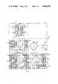
- FIG. 1illustrates a typical cathode array tube (CRT) display of this invention.
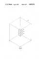
- FIG. 2aillustrates a three-dimensional representation made up of rectangular solid cells.
- FIG. 2billustrates the representation of FIG. 2a, but using spherical cells.
- FIGS. 3a and 3billustrate a three-dimensional representation from different viewing angles.
- FIG. 4is a block diagram of the computer system of this invention.
- FIG. 5illustrates the creating of the three-dimensional representation.
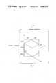
- FIG. 6shows the measurement requirements for creating the three-dimensional cell.
- FIG. 1illustrates a typical presentation on the video display 20 of the Lisp computing system 10 shown in FIG. 4.
- the system used in this preferred embodimentis a LAMBDA computing system from Lisp Machine, Inc., designed for execution of LISP program instructions.
- the LAMBDA system and the use of the LISP programsare set out in detail in the following manuals of Lisp Machine, Inc.:
- Field 31acontains a three-dimensional (3-D) representation of a 3-D volume. As shown in FIG. 1, this 3-D representation has been excavated to display the volumes shown as 30a, 30b, 35 and 36. Before the excavation, the display would have typically been of a 3-D representation of a rectangular solid.
- the rectangular solidis a tessellation of cells such as 35, 36, which in this preferred embodiment, are also rectangular solids. In the accompanying Lisp program, the cells are referred to as "voxels".
- Field 31bis a top view of the 3-D representation of field 31a illustrating top surfaces 32 and 38, as well as the individual cells 35 and 36.
- Field 31cis a front view of the 3-D representation of field 31a illustrating solids 30a and 30b, and cells 35 and 36.
- Field 31dis a right side view of the 3-D representation of field 31a with volume 30b visible, along with cells 35 and 36.
- field 31eillustrates a positioning mechanism for specifying viewing the front, left, back and right sides by indication on dial 43.
- the top, bottom and sidemay be viewed by indication on dial 44.
- the computer systemincludes a cursor which is movable in the face of the display by moving mouse 21 of FIG. 4.
- the cursor(not shown) may point at any specific cell in any of fields 31a-31d.
- an excavationis then electronically accomplished by activating a switch on the mouse 21.
- This programis described in detail. Also, the program for causing the viewing angle to change via dial 43 and dial 44 is explained in detail.
- FIG. 2aillustrates a three--dimensional representation after an excavation has been performed showing solid object 51 with cells 52.
- FIG. 2bshows a similar structure, but from a different view angle and also using spheres 62 as the cell configuration in place of the rectangular solid cells 52 of FIG. 2a.
- the rectangular solidis the preferred cell in this embodiment, spheres or other geometric volumes could be used.
- FIG. 3ashows a three-dimensional representation 71 made up of rectangular solid cells 72.
- FIG. 3bshows that the same three-dimensional representation 71 with cells 72 from a different viewing angle.
- FIGS. 2a-2b and FIGS. 3a-3bare not shown in color or in shading. It should be noted, however, that the cells are customarily colored in accordance with designating digital numbers. It should also be noted that in this preferred embodiment, seismic data provides the three-dimensional source data. Any other appropriate data would serve as well. For example, Nuclear Magnetic Resonance (NMR) imagery is contemplated.
- NMRNuclear Magnetic Resonance
- FIG. 4illustrates the LISP machine of this invention.
- a LISP processor 11is connected via bus 17 (a Texas Instruments NUBUS type bus to a Motorola 68,000 processor 12, main memory 13, display controller 14 and system diagnostic unit 15.
- the main memory 13stores the three-dimensional data array and the designator bit array.
- a display controller 14controls video display 20 which is connected to RS232 interface 18. Keyboard 22 and mouse 21 are interfaced to the video display 20.
- the details of system 10may be referred to in the aforementioned LISP Machine, Inc. publications.
- FIGS. 5 and 6Please refer to FIGS. 5 and 6, in particular, together with the other figures, for an understanding of the operation of this invention.
- a 3D array (volume) of numbers(e.g. 3D seismic or NMR data).
- the Data Arrayis referred to as the VOXEL-COLOR, a 3D array of integers in [0:15].
- the dataTo diplay a different range of values using this program, the data must first be converted to an array containing numbers in [0:15].
- the [0:15]numberscorrespond to the sixteen colors of the particular display software used by the program.
- a one-bitdesignates the corresponding datum to be included in the display, and a zero-bit designates that it will not be included.
- a datum which is designated for displaywill not actually be visible in the display if other designated data occlude it. Note: In the program the Designator Array is referred to as the POINT-ARRAY.
- Two angles, theta and phirespectively specify the vertical and horizontal components of the 3D viewing angle, as in a sperical coordinate system.
- the X and Y axes of the Data Arrayare arbitrarily regarded as lying in a horizontal plane, and the positive direction along the (vertical) Z dimension is regarded as pointing upward.
- Theta and phican be converted to a VIEW-VECTOR, the actual input expected by the program, using the VIEW-ANGLE function (in file: VIEW-ANGLE).
- Each cell of the Data Arrayis displayed as a small cube or sphere (voxel) when the corresponding Designator Array bit is one (1).
- the displayed color or shade of the voxelis specified by the corresponding number in the Data Array.
- the displayappears as a large rectangular solid with a colored surface that varies in proportion to the corresponding Data Array values.
- all designator bitsare zero, nothing appears in the display.
- the primary use of this methodis to examine volumes by selecting some designator bits to be one (1) and others to be zero, resulting in a display representing a carving of the Data Array into arbitrary 3D shapes, voxel by voxel.
- FIG. 5illustrates cells 81, 82, and 83 being created in the farthest corner of prospective 3-D representation 80. First, cell 81 is created, then 82, 83, and so on, until the column is completed. Then, the next designated adjacent column is created.
- One of the problems solved by the COMPUTE-ORIGIN-AND-VIEWING-CONSTANTS method in the programis to determine an appropriate size for each voxel so that the display of the entire volume will fit in the window.
- the summary of the method belowis simplified by assuming that the window is big enough to accommodate an arbitrarily chosen voxel size.
- STEP 1Let XMAX, YMAX, and ZMAX be the maximum subscripts of the Data Array in the three dimensions. The minimum subscript of each dimension is zero.
- VIEW-VECTOR(A B C) be a vector pointing in the direction of gaze (this represents the viewing angle).
- STEP 2Compute the SCAN-ORDER. That is, determine an order for scanning the Data Array "from farthest to nearest" with respect to the viewer.
- the scan orderis represented as a list of three numbers, (DX DY DZ).
- DY and DZrepresent the scan order with respect to the Y and Z axes.
- the VERTICES indicated as P0, PX, PY, and PZrepresent the same points as AO, AX, AY, and AZ, except there the origin of the array is regarded as being at the center of the array instead of at (0 0 0).
- the programuses the other origin as part of a scheme for centering the center of the Data Array in the window regardless of the particular designator and viewing angle.
- STEP 4Compute the image of AO, AX, AY, and AZ.
- WO(wxo,wyo)
- WX(wxx,wyx)
- WY(wxy,wyy)
- WZ(wxz,wyz)
- the VIEW-TRANSFORMATION functionperforms the projection.
- the WINDOW-TRANSFORMATION functionis part of the scaling to translate the image coordinates into window coordinates. Without loss of generality, the rest of this discussion assumes that WO, WX, WY, AND WZ are in window coordinates.
- STEP 5Compute five constants, Xdx, Ydx, Xdy, Ydy, and Zdy, corresponding to the distances in the FIG. 6.
- the drawingillustrates one voxel depicted as a small cube.
- the importance of the five constantsis that they describe the directional displacements in the image between adjacent voxels.
- Zdydescribes the vertical displacement (dy) of two voxels in the image due to a unit displacement in the scanning direction along the Z axis of the Data Array, i.e. the displacement between two voxels corresponding to Data Array positions, (X,Y,Z) and (X,Y,Z+DZ).
- (Xdx Xdy)describes the combined horizontal (dx) and vertical (dy) displacement of two voxels due to a unit displacement along the X axis of the Data Array.
- (Ydx Ydy)describes the combined horizontal (dx) and vertical (dy) displacement of two voxels due to a unit displacement along the Y axis of the Data Array.
- the five constantscan be computed using the SCAN-ORDER, WO, WX, WY, WZ, XMAX, and ZMAX as follows, where the asterisk denotes multiplication: ##EQU1##
- STEP 6Compute a picture of the voxel.
- the particular picture used to represent each voxelis arbitrary. Drawing small cubes produces attractive displays.
- the pictureonly needs to be computed once and saved for replication, since under orthographic projection the shape and size of each Data Array cell is the same.
- the coloring or shading of voxels in accordance with the Data Array valuesis accomplished separately during the innermost loop of Step 8.
- the MASKhas one (1) bits everywhere the voxel is depicted as opaque. In the innermost loop of Step 8, the MASK is used to erase the appropriate area of the window in preparation for inserting the PICTURE, using a series of calls to the Lisp Machine BITBLT function.
- the ORIGINis computed from WO, WX, WY, and WZ using the signs (plus or minus) of DX, DY, and DZ, by the relationship in the following table, where the operations are vector addition and subtraction.
- STEP 8Scan the Designator Array and Data Array in the scanning order, drawing the voxel picture for each designated datum in sequence.
- This stepis extremely efficient since the positions of voxels in the window can be determined with just a small number of additions and comparisons per voxel, and because the series of BITBLT operations used to copy each voxel picture into the screen exploits the speed of BITBLT.
- This stepconsists of three nested loops. The outermost loop steps X along the X axis of the Data Array and keeps track of the displacement of each voxel from the ORIGIN due to the displacement of X along the X axis.
- the middle loopsteps Y along the Y axis and keeps track of the displacement from the ORIGIN due to the displacement of Y.
- the innermost loopsteps Z along the Z axis, keeps track of the displacement due to Z, and draws the voxel at the window position corresponding to Data Array position (X Y Z) when the (X Y Z) designator bit is one (1).
- VIS001.LSPis entitled "Array-Display, Lisp”.
- This programis employed in the system to implement the display of the top, front, and sides view in fields 31b, 31c and 31d, respectively, of FIG. 1.
- This short programdefines a virtual window of an array that is updated when the array itself is altered as by an excavation procedure.
- the virtual window techniqueis set out in program VIS009.LSP entitled "Virtual-Windows. Lisp".
- the virtual window systemis described in the introductory material to the program VIS009.LSP.
- Program VIS003.LSP entitled “Color-Graphics.Lisp”is a low level primitive program which is used for drawing each cell and is employed in program VIS010.LSP--entitled “Volume-Display Method.Lisp", previously described.
- Program VIS004.LSP entitled "Dashboard-Dials.Lisp”is a program for drawing the dials as shown in field 31e of FIG. 1.
- Program VIS005.LSP entitled “Mouse-Handler-Mixin.Lisp” and program VIS006.LSP entitled “Mouse-Handler-Utilities.Lisp”describe a method for moving and operating mouse 21 of FIG. 4.
- a cursoris employed to point to cells in any of fields 31a-31d of FIG. 1 and also to desired directions in field 31e.
- a cellmay be created or deleted by "clicking" the mouse on cells of the solid object in field 31a. The first click highlights a cell at one corner of a rectangular volume to be created or deleted, and the second click specifies the opposite corner and performs the operation.
- the left mouse buttonis for creating and the middle button is for deleting.
- a single clickspecifies the visible cell at the mouse cursor and a double clock specifies an empty cell location closest to the viewpoint at the mouse cursor.
- a triple clickcancels a partially completed operation.
- cellscan be created or deleted by specifying opposite corners of a rectangle in one of the three mutually orthogonal silhouette view windows illustrated in fields 31b-31d.
- cellsare created or deleted at all cell locations in-line with the specified rectangle from that point of view. For example, when a rectangle is specified in the top view field 31b, all cells in the columns directly under the rectangle are affected.
- the first click of the mousemarks the position of one corner and the second click marks the opposite corner of the rectangle (which may degenerate to a single element or row). Both clicks must be of the same type (left: create or middle: delete).
- a cellcan be created or deleted at a single point by clicking the two points in different orthogonal views.
- the angle from which the 3-D display is viewedis changed by clicking the dials in the viewing position window 31e.
- the dialsare designed as if the object is at the center of each dial and the viewpoint is on the perimeter.
- Dial 43controls the horizontal component of the viewing position
- dial 44specifies the vertical component.
- the program VIS003.LSP entitled "Color-Graphics.Lisp”controls how the cells are colored, either collectively or individually. For example, a list of six colors, one for each of the six faces, causes cube cell faces to be uniformly colored--all Right faces are, for example, blue while all Top faces are red. Cells can also be individually colored by specifying a 3-D array of colors where the color of a cell is the color in the color array position corresponding to the cell position in the 3-D bit array.
- Program VIS007.LSP entitled “Movie.Lisp”provides for producing two types of movies: (1) the object rotating in place, and (2) a scan of the object as it appears while it is being drawn one frame per plane of the solid object.
- Movies of the object rotating in placeare made by specifying a starting viewing position and a final view (the last frame of the movie).
- the N frames of the movieare then interpolated between the two views; the horizon viewing position from dial 43 advances counter-clockwise.
- the starting viewis specified before performing the make movie command.
- another windowprovides for optionally changing some default parameters of the movie (e.g. the number of frames).
- the programsolicits the final view specification as specified in field 31e. Clicking the middle button of the mouse 21 produces the movie; clicking the Right button aborts the procedure.
- the scanning moviesdepict the solid object as it is being drawn, one frame per plane, in any of six scanning directions (i.e., top-to-bottom, right-to-left, etc.). Scanning movies allow extremely rapid browsing of planar sections of the object, incrementally building up and tearing down the solid object plane by plane (frame by frame).
- a move dialappears in the viewing position window 31e for controlling the showing of the movie interactively using the Movie Display system on the Lisp machine.
- Program VIS011.LSP entitled “Volume Inspector Method.Lisp”, as can be seen,is the program employed for the excavation feature. The method of this program is described above.
- program VIS012.LSP entitled “Windows.Lisp”is a low level primitive program for creating the windows in FIG. 1 to contain fields 31a-31e, plus the blank field.
Landscapes
- Physics & Mathematics (AREA)
- Engineering & Computer Science (AREA)
- Computer Graphics (AREA)
- Geometry (AREA)
- Software Systems (AREA)
- General Physics & Mathematics (AREA)
- Theoretical Computer Science (AREA)
- Image Generation (AREA)
- Processing Or Creating Images (AREA)
- Apparatus For Radiation Diagnosis (AREA)
- Eye Examination Apparatus (AREA)
Abstract
Description
______________________________________ DX DY DZ => ORIGIN ______________________________________ + + + WO + + - WZ + - + WY + - - WY + (WZ - WO) - + + WX - + - WX + (WZ - WO) - - + WX + (WY - WO) - - - WX + (WY - WO) + (WZ - WO) ______________________________________
______________________________________ (loop for X from 0 to XMAX by DX as WXx = Ox then (+ WXx Xdx) as WXy = Oy then (+ WXy Xdy) do (loop for Y from 0 to YMAX by DY as WYx = WXx then (+ WYx Ydx) as WYy = WXy then (+ WYy Ydy) do (loop for Z from 0 to ZMAX by DY as WZy = WYy then (+ WZy Zdy) do ;At this point, when the Designator Array bit ;at (X Y Z) is one (1), the voxel picture is ;copied into the window at (WYx WZy): A ;series of BITBLT operations on PICTURE and ;MASK is performed to produce a picture in the ;color specified by the number in the Data ;Array at (X Y Z). ______________________________________
Claims (11)
Priority Applications (4)
| Application Number | Priority Date | Filing Date | Title |
|---|---|---|---|
| US06/637,465US4685070A (en) | 1984-08-03 | 1984-08-03 | System and method for displaying, and interactively excavating and examining a three dimensional volume |
| NO853061ANO853061L (en) | 1984-08-03 | 1985-08-02 | PROCEDURE AND FACILITIES FOR DISPLAY AND FOR INTERACTIVE EXCAVATION AND INSPECTION OF A THREE-DIMENSIONAL VOLUME. |
| CA000488015ACA1246239A (en) | 1984-08-03 | 1985-08-02 | System and method for displaying and interactively excavating and examining a three dimensional volume |
| EP85305540AEP0180296A3 (en) | 1984-08-03 | 1985-08-02 | System and method for displaying and interactively excavating and examining a three dimensional volume |
Applications Claiming Priority (1)
| Application Number | Priority Date | Filing Date | Title |
|---|---|---|---|
| US06/637,465US4685070A (en) | 1984-08-03 | 1984-08-03 | System and method for displaying, and interactively excavating and examining a three dimensional volume |
Publications (1)
| Publication Number | Publication Date |
|---|---|
| US4685070Atrue US4685070A (en) | 1987-08-04 |
Family
ID=24556064
Family Applications (1)
| Application Number | Title | Priority Date | Filing Date |
|---|---|---|---|
| US06/637,465Expired - LifetimeUS4685070A (en) | 1984-08-03 | 1984-08-03 | System and method for displaying, and interactively excavating and examining a three dimensional volume |
Country Status (4)
| Country | Link |
|---|---|
| US (1) | US4685070A (en) |
| EP (1) | EP0180296A3 (en) |
| CA (1) | CA1246239A (en) |
| NO (1) | NO853061L (en) |
Cited By (72)
| Publication number | Priority date | Publication date | Assignee | Title |
|---|---|---|---|---|
| US4775946A (en)* | 1985-03-29 | 1988-10-04 | Hitachi, Ltd. | Method for constructing three-dimensional polyhedron model |
| US4817005A (en)* | 1985-07-05 | 1989-03-28 | Dai Nippon Insatsu Kabushiki Kaisha | Method of designing cubic receptacle and apparatus therefor |
| US4821214A (en)* | 1986-04-17 | 1989-04-11 | Brigham Young University | Computer graphics method for changing the shape of a geometric model using free-form deformation |
| US4821210A (en)* | 1987-04-02 | 1989-04-11 | General Electric Co. | Fast display of three-dimensional images |
| US4835712A (en)* | 1986-04-14 | 1989-05-30 | Pixar | Methods and apparatus for imaging volume data with shading |
| US4845651A (en)* | 1985-11-01 | 1989-07-04 | Hitachi, Ltd. | Geometric modelling system |
| US4845656A (en)* | 1985-12-12 | 1989-07-04 | Kabushiki Kaisha Toshiba | System for transferring data between memories in a data-processing apparatus having a bitblt unit |
| US4858150A (en)* | 1986-06-27 | 1989-08-15 | Hitachi, Ltd. | Shape modeling system |
| US4860217A (en)* | 1984-12-27 | 1989-08-22 | Sony Corporation | Method and system for effecting a transformation of a video image |
| US4876673A (en)* | 1988-01-19 | 1989-10-24 | Mobil Oil Corporation | Display of common depth point seismic data with velocity correction in real time |
| US4884069A (en)* | 1987-03-19 | 1989-11-28 | Apple Computer, Inc. | Video apparatus employing VRAMs |
| US4888713A (en)* | 1986-09-05 | 1989-12-19 | Cdi Technologies, Inc. | Surface detail mapping system |
| US4907188A (en)* | 1985-09-12 | 1990-03-06 | Kabushiki Kaisha Toshiba | Image information search network system |
| US4928233A (en)* | 1987-08-24 | 1990-05-22 | International Business Machines | System for providing three dimensional object descriptions |
| US4965844A (en)* | 1985-04-03 | 1990-10-23 | Sony Corporation | Method and system for image transformation |
| US4982438A (en)* | 1987-06-02 | 1991-01-01 | Hitachi, Ltd. | Apparatus and method for recognizing three-dimensional shape of object |
| US4987554A (en)* | 1988-08-24 | 1991-01-22 | The Research Foundation Of State University Of New York | Method of converting continuous three-dimensional geometrical representations of polygonal objects into discrete three-dimensional voxel-based representations thereof within a three-dimensional voxel-based system |
| US5019809A (en)* | 1988-07-29 | 1991-05-28 | University Of Toronto Innovations Foundation | Two-dimensional emulation of three-dimensional trackball |
| US5067098A (en)* | 1989-03-31 | 1991-11-19 | The Ohio State University Research Foundation | Slope-aspect color shading for parametric surfaces |
| US5081698A (en)* | 1989-02-14 | 1992-01-14 | Intel Corporation | Method and apparatus for graphics display data manipulation |
| US5113357A (en)* | 1989-05-18 | 1992-05-12 | Sun Microsystems, Inc. | Method and apparatus for rendering of geometric volumes |
| US5129013A (en)* | 1987-10-13 | 1992-07-07 | At&T Bell Laboratories | Graphics image editor |
| US5133073A (en)* | 1990-05-29 | 1992-07-21 | Wavetracer, Inc. | Processor array of N-dimensions which is physically reconfigurable into N-1 |
| US5157785A (en)* | 1990-05-29 | 1992-10-20 | Wavetracer, Inc. | Process cell for an n-dimensional processor array having a single input element with 2n data inputs, memory, and full function arithmetic logic unit |
| US5201035A (en)* | 1990-07-09 | 1993-04-06 | The United States Of America As Represented By The Secretary Of The Air Force | Dynamic algorithm selection for volume rendering, isocontour and body extraction within a multiple-instruction, multiple-data multiprocessor |
| US5255207A (en)* | 1988-06-16 | 1993-10-19 | Larry Cornwell | Method for designing and detailing cabinets |
| US5296846A (en)* | 1990-10-15 | 1994-03-22 | National Biomedical Research Foundation | Three-dimensional cursor control device |
| US5298919A (en)* | 1991-08-02 | 1994-03-29 | Multipoint Technology Corporation | Multi-dimensional input device |
| US5303388A (en)* | 1990-05-09 | 1994-04-12 | Apple Computer, Inc. | Method to display and rotate a three-dimensional icon with multiple faces |
| US5317689A (en)* | 1986-09-11 | 1994-05-31 | Hughes Aircraft Company | Digital visual and sensor simulation system for generating realistic scenes |
| US5319395A (en)* | 1990-05-16 | 1994-06-07 | International Business Machines Corporation | Pixel depth converter for a computer video display |
| US5335317A (en)* | 1990-03-28 | 1994-08-02 | Hitachi, Ltd. | Method and apparatus for displaying three dimensional physical quantity |
| US5339390A (en)* | 1990-03-05 | 1994-08-16 | Xerox Corporation | Operating a processor to display stretched continuation of a workspace |
| US5359704A (en)* | 1991-10-30 | 1994-10-25 | International Business Machines Corporation | Method for selecting silhouette and visible edges in wire frame images in a computer graphics display system |
| US5434966A (en)* | 1991-05-31 | 1995-07-18 | Kao Corporation | System and method for storing and retrieving three dimensional shapes using two dimensional contrast images |
| US5442734A (en)* | 1991-03-06 | 1995-08-15 | Fujitsu Limited | Image processing unit and method for executing image processing of a virtual environment |
| US5454068A (en)* | 1991-02-25 | 1995-09-26 | International Business Machines Corporation | Scientific visualization system |
| US5457755A (en)* | 1989-02-08 | 1995-10-10 | Canon Kabushiki Kaisha | Figure processing apparatus |
| US5546529A (en)* | 1994-07-28 | 1996-08-13 | Xerox Corporation | Method and apparatus for visualization of database search results |
| US5555352A (en)* | 1991-04-23 | 1996-09-10 | International Business Machines Corporation | Object-based irregular-grid volume rendering |
| US5557714A (en)* | 1993-01-29 | 1996-09-17 | Microsoft Corporation | Method and system for rotating a three-dimensional model about two orthogonal axes |
| US5594850A (en)* | 1993-01-29 | 1997-01-14 | Hitachi, Ltd. | Image simulation method |
| US5617332A (en)* | 1988-08-10 | 1997-04-01 | Fressola; Alfred A. | Method and system for producing stereographic images of celestial objects |
| WO1997014134A1 (en)* | 1995-10-09 | 1997-04-17 | Balco, Incorporated | Viewer orientation indicator for an illustration |
| GB2309142A (en)* | 1996-01-12 | 1997-07-16 | Fujitsu Ltd | Drawing three-dimensional objects in computer-aided design systems |
| GB2316591A (en)* | 1996-07-05 | 1998-02-25 | Int Technical Publication Co L | Producing isometric view from manipulated plual planar views in CAD system |
| US5734384A (en)* | 1991-11-29 | 1998-03-31 | Picker International, Inc. | Cross-referenced sectioning and reprojection of diagnostic image volumes |
| US5786820A (en)* | 1994-07-28 | 1998-07-28 | Xerox Corporation | Method and apparatus for increasing the displayed detail of a tree structure |
| US5798750A (en)* | 1994-09-28 | 1998-08-25 | Nikon Corporation | Image display apparatus |
| US5838889A (en)* | 1992-01-29 | 1998-11-17 | Apple Computer, Inc. | Method and apparatus for flipping a double-sided graphic image having different sized first and second sides |
| US5847971A (en)* | 1996-01-05 | 1998-12-08 | Steelcase Incorporated | 3-D spatial GUI querying and manipulating an RDMS for order-entry applications |
| US6011556A (en)* | 1991-03-29 | 2000-01-04 | Fujitsu Limited | Automatic apparatus for drawing image of three-dimensional object on a screen |
| US6081253A (en)* | 1998-02-10 | 2000-06-27 | Bronson Color Company, Inc. | Method for generating numerous harmonious color palettes from two colors |
| US6111583A (en)* | 1997-09-29 | 2000-08-29 | Skyline Software Systems Ltd. | Apparatus and method for three-dimensional terrain rendering |
| US6144384A (en)* | 1996-02-20 | 2000-11-07 | Yugen Kashia Aloalo International | Voxel data processing using attributes thereof |
| US6144383A (en)* | 1997-05-30 | 2000-11-07 | Hewlett-Packard Company | Volumetric data organization method that allows for cache efficient rendering speedups and efficient graphics hardware design |
| US6240308B1 (en)* | 1988-12-23 | 2001-05-29 | Tyrone L. Hardy | Method and apparatus for archiving and displaying anatomico-physiological data in a normalized whole brain mapping and imaging system |
| US6384847B1 (en) | 1992-03-20 | 2002-05-07 | International Business Machines Corporation | Interactive graphical method for analyzing many-dimensional data sets |
| US6545676B1 (en)* | 1999-05-24 | 2003-04-08 | Parametric Technology Corporation | Method and system for creating a tessellated approximation of an outer envelope of a complex model |
| US6580428B1 (en)* | 1999-05-24 | 2003-06-17 | Parametric Technology Corporation | Method and system for identifying peripheral elements of a complex model |
| EP1085405A3 (en)* | 1999-09-13 | 2003-08-06 | Solidworks Corporation | Electronic drawing viewer |
| GB2387754A (en)* | 2002-04-17 | 2003-10-22 | John Morrison | Representing information as 3D image |
| US6735888B2 (en)* | 2001-05-18 | 2004-05-18 | Witten Technologies Inc. | Virtual camera on the bucket of an excavator displaying 3D images of buried pipes |
| US20040125103A1 (en)* | 2000-02-25 | 2004-07-01 | Kaufman Arie E. | Apparatus and method for volume processing and rendering |
| US6798409B2 (en)* | 2000-02-07 | 2004-09-28 | British Broadcasting Corporation | Processing of images for 3D display |
| US6821204B2 (en) | 2002-05-17 | 2004-11-23 | Nintendo Co., Ltd. | Game system and game program |
| US20040246234A1 (en)* | 2001-03-01 | 2004-12-09 | Luis Serra | Display apparatus |
| US20090196511A1 (en)* | 2004-07-07 | 2009-08-06 | The Government Of The Us, As Represented By The Secretary Of The Navy | System, method, and apparatus for clustering features using an expansion shape |
| US20090231333A1 (en)* | 1999-02-26 | 2009-09-17 | Ronnie Yaron | Sending three-dimensional images over a network |
| US20100053163A1 (en)* | 2008-08-26 | 2010-03-04 | Leica Geosystems Ag | Point-cloud clip filter |
| US20100245542A1 (en)* | 2007-08-02 | 2010-09-30 | Inha-Industry Partnership Institute | Device for computing the excavated soil volume using structured light vision system and method thereof |
| US11498004B2 (en)* | 2020-06-23 | 2022-11-15 | Nintendo Co., Ltd. | Computer-readable non-transitory storage medium having instructions stored therein, game apparatus, game system, and game processing method |
Citations (9)
| Publication number | Priority date | Publication date | Assignee | Title |
|---|---|---|---|---|
| US3638178A (en)* | 1969-12-01 | 1972-01-25 | Chevron Res | Method for processing three-dimensional seismic data to select and plot said data on a two-dimensional display surface |
| US3668619A (en)* | 1969-07-02 | 1972-06-06 | Mobil Oil Corp | Three-dimensional presentation of borehole logging data |
| US4439760A (en)* | 1981-05-19 | 1984-03-27 | Bell Telephone Laboratories, Incorporated | Method and apparatus for compiling three-dimensional digital image information |
| US4475104A (en)* | 1983-01-17 | 1984-10-02 | Lexidata Corporation | Three-dimensional display system |
| US4484187A (en)* | 1982-06-25 | 1984-11-20 | At&T Bell Laboratories | Video overlay system having interactive color addressing |
| US4509043A (en)* | 1982-04-12 | 1985-04-02 | Tektronix, Inc. | Method and apparatus for displaying images |
| US4538144A (en)* | 1981-01-16 | 1985-08-27 | Tokyo Shibaura Denki Kabushiki Kaisha | Graphic display device having graphic generator for shading graphs |
| US4574357A (en)* | 1984-02-21 | 1986-03-04 | Pitney Bowes Inc. | Real time character thinning system |
| US4580134A (en)* | 1982-11-16 | 1986-04-01 | Real Time Design, Inc. | Color video system using data compression and decompression |
- 1984
- 1984-08-03USUS06/637,465patent/US4685070A/ennot_activeExpired - Lifetime
- 1985
- 1985-08-02CACA000488015Apatent/CA1246239A/ennot_activeExpired
- 1985-08-02NONO853061Apatent/NO853061L/enunknown
- 1985-08-02EPEP85305540Apatent/EP0180296A3/ennot_activeWithdrawn
Patent Citations (9)
| Publication number | Priority date | Publication date | Assignee | Title |
|---|---|---|---|---|
| US3668619A (en)* | 1969-07-02 | 1972-06-06 | Mobil Oil Corp | Three-dimensional presentation of borehole logging data |
| US3638178A (en)* | 1969-12-01 | 1972-01-25 | Chevron Res | Method for processing three-dimensional seismic data to select and plot said data on a two-dimensional display surface |
| US4538144A (en)* | 1981-01-16 | 1985-08-27 | Tokyo Shibaura Denki Kabushiki Kaisha | Graphic display device having graphic generator for shading graphs |
| US4439760A (en)* | 1981-05-19 | 1984-03-27 | Bell Telephone Laboratories, Incorporated | Method and apparatus for compiling three-dimensional digital image information |
| US4509043A (en)* | 1982-04-12 | 1985-04-02 | Tektronix, Inc. | Method and apparatus for displaying images |
| US4484187A (en)* | 1982-06-25 | 1984-11-20 | At&T Bell Laboratories | Video overlay system having interactive color addressing |
| US4580134A (en)* | 1982-11-16 | 1986-04-01 | Real Time Design, Inc. | Color video system using data compression and decompression |
| US4475104A (en)* | 1983-01-17 | 1984-10-02 | Lexidata Corporation | Three-dimensional display system |
| US4574357A (en)* | 1984-02-21 | 1986-03-04 | Pitney Bowes Inc. | Real time character thinning system |
Non-Patent Citations (6)
| Title |
|---|
| "Experiences with New Image Component Algorithms", Samet., Eurographic 84; K.B0 and H. A. Tucker; Elsevier Science Publishers B. V., Holland 1984. |
| "Three Dimensional Deta Input by Selection of Hierarchially Defined Blocks", Yamaguchi et al., Eurographics 84 K.B0 and H. A. Tucker Elsevier Holland Science Publishers B. V. 1984. |
| "Two Display Algorithms for Octrees"; Oliver, Eurographics 84, K. B0 and H. A. Tucker, Elsevier Science Publishers B. V. (Holland), 1984. |
| Experiences with New Image Component Algorithms , Samet., Eurographic 84 ; K.B0 and H. A. Tucker; Elsevier Science Publishers B. V., Holland 1984.* |
| Three Dimensional Deta Input by Selection of Hierarchially Defined Blocks , Yamaguchi et al., Eurographics 84 K.B0 and H. A. Tucker Elsevier Holland Science Publishers B. V. 1984.* |
| Two Display Algorithms for Octrees ; Oliver, Eurographics 84, K. B0 and H. A. Tucker, Elsevier Science Publishers B. V. (Holland), 1984.* |
Cited By (93)
| Publication number | Priority date | Publication date | Assignee | Title |
|---|---|---|---|---|
| US4860217A (en)* | 1984-12-27 | 1989-08-22 | Sony Corporation | Method and system for effecting a transformation of a video image |
| US4775946A (en)* | 1985-03-29 | 1988-10-04 | Hitachi, Ltd. | Method for constructing three-dimensional polyhedron model |
| US4965844A (en)* | 1985-04-03 | 1990-10-23 | Sony Corporation | Method and system for image transformation |
| US4817005A (en)* | 1985-07-05 | 1989-03-28 | Dai Nippon Insatsu Kabushiki Kaisha | Method of designing cubic receptacle and apparatus therefor |
| US4907188A (en)* | 1985-09-12 | 1990-03-06 | Kabushiki Kaisha Toshiba | Image information search network system |
| US4845651A (en)* | 1985-11-01 | 1989-07-04 | Hitachi, Ltd. | Geometric modelling system |
| US4845656A (en)* | 1985-12-12 | 1989-07-04 | Kabushiki Kaisha Toshiba | System for transferring data between memories in a data-processing apparatus having a bitblt unit |
| US4835712A (en)* | 1986-04-14 | 1989-05-30 | Pixar | Methods and apparatus for imaging volume data with shading |
| US4821214A (en)* | 1986-04-17 | 1989-04-11 | Brigham Young University | Computer graphics method for changing the shape of a geometric model using free-form deformation |
| US4858150A (en)* | 1986-06-27 | 1989-08-15 | Hitachi, Ltd. | Shape modeling system |
| US4888713A (en)* | 1986-09-05 | 1989-12-19 | Cdi Technologies, Inc. | Surface detail mapping system |
| US5317689A (en)* | 1986-09-11 | 1994-05-31 | Hughes Aircraft Company | Digital visual and sensor simulation system for generating realistic scenes |
| US4884069A (en)* | 1987-03-19 | 1989-11-28 | Apple Computer, Inc. | Video apparatus employing VRAMs |
| US4821210A (en)* | 1987-04-02 | 1989-04-11 | General Electric Co. | Fast display of three-dimensional images |
| US4982438A (en)* | 1987-06-02 | 1991-01-01 | Hitachi, Ltd. | Apparatus and method for recognizing three-dimensional shape of object |
| US4928233A (en)* | 1987-08-24 | 1990-05-22 | International Business Machines | System for providing three dimensional object descriptions |
| US5129013A (en)* | 1987-10-13 | 1992-07-07 | At&T Bell Laboratories | Graphics image editor |
| US4876673A (en)* | 1988-01-19 | 1989-10-24 | Mobil Oil Corporation | Display of common depth point seismic data with velocity correction in real time |
| US5255207A (en)* | 1988-06-16 | 1993-10-19 | Larry Cornwell | Method for designing and detailing cabinets |
| US5019809A (en)* | 1988-07-29 | 1991-05-28 | University Of Toronto Innovations Foundation | Two-dimensional emulation of three-dimensional trackball |
| US5617332A (en)* | 1988-08-10 | 1997-04-01 | Fressola; Alfred A. | Method and system for producing stereographic images of celestial objects |
| US4987554A (en)* | 1988-08-24 | 1991-01-22 | The Research Foundation Of State University Of New York | Method of converting continuous three-dimensional geometrical representations of polygonal objects into discrete three-dimensional voxel-based representations thereof within a three-dimensional voxel-based system |
| US6240308B1 (en)* | 1988-12-23 | 2001-05-29 | Tyrone L. Hardy | Method and apparatus for archiving and displaying anatomico-physiological data in a normalized whole brain mapping and imaging system |
| US5457755A (en)* | 1989-02-08 | 1995-10-10 | Canon Kabushiki Kaisha | Figure processing apparatus |
| US5081698A (en)* | 1989-02-14 | 1992-01-14 | Intel Corporation | Method and apparatus for graphics display data manipulation |
| JP3023685B2 (en) | 1989-02-14 | 2000-03-21 | インテル・コーポレーシヨン | Image display data processing device |
| US5067098A (en)* | 1989-03-31 | 1991-11-19 | The Ohio State University Research Foundation | Slope-aspect color shading for parametric surfaces |
| US5113357A (en)* | 1989-05-18 | 1992-05-12 | Sun Microsystems, Inc. | Method and apparatus for rendering of geometric volumes |
| US5339390A (en)* | 1990-03-05 | 1994-08-16 | Xerox Corporation | Operating a processor to display stretched continuation of a workspace |
| US5335317A (en)* | 1990-03-28 | 1994-08-02 | Hitachi, Ltd. | Method and apparatus for displaying three dimensional physical quantity |
| US5303388A (en)* | 1990-05-09 | 1994-04-12 | Apple Computer, Inc. | Method to display and rotate a three-dimensional icon with multiple faces |
| US5452414A (en)* | 1990-05-09 | 1995-09-19 | Apple Computer, Inc. | Method of rotating a three-dimensional icon to its original face |
| US5319395A (en)* | 1990-05-16 | 1994-06-07 | International Business Machines Corporation | Pixel depth converter for a computer video display |
| US5133073A (en)* | 1990-05-29 | 1992-07-21 | Wavetracer, Inc. | Processor array of N-dimensions which is physically reconfigurable into N-1 |
| US5157785A (en)* | 1990-05-29 | 1992-10-20 | Wavetracer, Inc. | Process cell for an n-dimensional processor array having a single input element with 2n data inputs, memory, and full function arithmetic logic unit |
| US5201035A (en)* | 1990-07-09 | 1993-04-06 | The United States Of America As Represented By The Secretary Of The Air Force | Dynamic algorithm selection for volume rendering, isocontour and body extraction within a multiple-instruction, multiple-data multiprocessor |
| US5296846A (en)* | 1990-10-15 | 1994-03-22 | National Biomedical Research Foundation | Three-dimensional cursor control device |
| US5454068A (en)* | 1991-02-25 | 1995-09-26 | International Business Machines Corporation | Scientific visualization system |
| US5442734A (en)* | 1991-03-06 | 1995-08-15 | Fujitsu Limited | Image processing unit and method for executing image processing of a virtual environment |
| US6011556A (en)* | 1991-03-29 | 2000-01-04 | Fujitsu Limited | Automatic apparatus for drawing image of three-dimensional object on a screen |
| US5555352A (en)* | 1991-04-23 | 1996-09-10 | International Business Machines Corporation | Object-based irregular-grid volume rendering |
| US5434966A (en)* | 1991-05-31 | 1995-07-18 | Kao Corporation | System and method for storing and retrieving three dimensional shapes using two dimensional contrast images |
| US5298919A (en)* | 1991-08-02 | 1994-03-29 | Multipoint Technology Corporation | Multi-dimensional input device |
| US5359704A (en)* | 1991-10-30 | 1994-10-25 | International Business Machines Corporation | Method for selecting silhouette and visible edges in wire frame images in a computer graphics display system |
| US5734384A (en)* | 1991-11-29 | 1998-03-31 | Picker International, Inc. | Cross-referenced sectioning and reprojection of diagnostic image volumes |
| US5838889A (en)* | 1992-01-29 | 1998-11-17 | Apple Computer, Inc. | Method and apparatus for flipping a double-sided graphic image having different sized first and second sides |
| US6115724A (en)* | 1992-01-29 | 2000-09-05 | Apple Computer, Inc. | Method and apparatus for displaying a double-sided graphic image |
| US6384847B1 (en) | 1992-03-20 | 2002-05-07 | International Business Machines Corporation | Interactive graphical method for analyzing many-dimensional data sets |
| US5557714A (en)* | 1993-01-29 | 1996-09-17 | Microsoft Corporation | Method and system for rotating a three-dimensional model about two orthogonal axes |
| US5594850A (en)* | 1993-01-29 | 1997-01-14 | Hitachi, Ltd. | Image simulation method |
| US5786820A (en)* | 1994-07-28 | 1998-07-28 | Xerox Corporation | Method and apparatus for increasing the displayed detail of a tree structure |
| US5546529A (en)* | 1994-07-28 | 1996-08-13 | Xerox Corporation | Method and apparatus for visualization of database search results |
| US5798750A (en)* | 1994-09-28 | 1998-08-25 | Nikon Corporation | Image display apparatus |
| AU709834B2 (en)* | 1995-10-09 | 1999-09-09 | Snap-On Technologies, Inc. | Viewer orientation indicator for an illustration |
| WO1997014134A1 (en)* | 1995-10-09 | 1997-04-17 | Balco, Incorporated | Viewer orientation indicator for an illustration |
| US5943037A (en)* | 1995-10-10 | 1999-08-24 | Snap-On Technologies, Inc. | Viewer orientation indicator for an illustration |
| US5847971A (en)* | 1996-01-05 | 1998-12-08 | Steelcase Incorporated | 3-D spatial GUI querying and manipulating an RDMS for order-entry applications |
| US6002855A (en)* | 1996-01-05 | 1999-12-14 | Steelcase Incorporated | 3-D spatial GUI for querying and manipulating an RDMS for order-entry applications |
| GB2309142A (en)* | 1996-01-12 | 1997-07-16 | Fujitsu Ltd | Drawing three-dimensional objects in computer-aided design systems |
| US5852442A (en)* | 1996-01-12 | 1998-12-22 | Fujitsu Limited | Method of drawing a three-dimensional object |
| GB2309142B (en)* | 1996-01-12 | 2000-03-29 | Fujitsu Ltd | Drawing three-dimensional objects in computer-aided design systems |
| US6144384A (en)* | 1996-02-20 | 2000-11-07 | Yugen Kashia Aloalo International | Voxel data processing using attributes thereof |
| GB2316591A (en)* | 1996-07-05 | 1998-02-25 | Int Technical Publication Co L | Producing isometric view from manipulated plual planar views in CAD system |
| GB2316591B (en)* | 1996-07-05 | 2000-11-08 | Internat Technical Publication | Apparatus of drawing a cubic view |
| US6144383A (en)* | 1997-05-30 | 2000-11-07 | Hewlett-Packard Company | Volumetric data organization method that allows for cache efficient rendering speedups and efficient graphics hardware design |
| US6433792B1 (en) | 1997-09-29 | 2002-08-13 | Skyline Software Systems, Inc. | Apparatus and method for three-dimensional terrain rendering |
| US6111583A (en)* | 1997-09-29 | 2000-08-29 | Skyline Software Systems Ltd. | Apparatus and method for three-dimensional terrain rendering |
| US6704017B1 (en) | 1997-09-29 | 2004-03-09 | Skyline Software Systems Ltd. | Method for determining scan direction for three-dimensional terrain rendering |
| US6081253A (en)* | 1998-02-10 | 2000-06-27 | Bronson Color Company, Inc. | Method for generating numerous harmonious color palettes from two colors |
| US8237713B2 (en) | 1999-02-26 | 2012-08-07 | Skyline Software Systems, Inc | Sending three-dimensional images over a network |
| US20090231333A1 (en)* | 1999-02-26 | 2009-09-17 | Ronnie Yaron | Sending three-dimensional images over a network |
| US6545676B1 (en)* | 1999-05-24 | 2003-04-08 | Parametric Technology Corporation | Method and system for creating a tessellated approximation of an outer envelope of a complex model |
| US6580428B1 (en)* | 1999-05-24 | 2003-06-17 | Parametric Technology Corporation | Method and system for identifying peripheral elements of a complex model |
| EP1460526A3 (en)* | 1999-09-13 | 2005-01-26 | Solidworks Corporation | Electronic drawing viewer |
| EP1085405A3 (en)* | 1999-09-13 | 2003-08-06 | Solidworks Corporation | Electronic drawing viewer |
| EP1462924A3 (en)* | 1999-09-13 | 2005-01-26 | Solidworks Corporation | Electronic drawing viewer |
| EP1462923A3 (en)* | 1999-09-13 | 2005-01-26 | Solidworks Corporation | Electronic drawing viewer |
| US6798409B2 (en)* | 2000-02-07 | 2004-09-28 | British Broadcasting Corporation | Processing of images for 3D display |
| US20040125103A1 (en)* | 2000-02-25 | 2004-07-01 | Kaufman Arie E. | Apparatus and method for volume processing and rendering |
| US7133041B2 (en) | 2000-02-25 | 2006-11-07 | The Research Foundation Of State University Of New York | Apparatus and method for volume processing and rendering |
| US20070206008A1 (en)* | 2000-02-25 | 2007-09-06 | The Research Foundation Of The State University Of New York | Apparatus and Method for Real-Time Volume Processing and Universal Three-Dimensional Rendering |
| US7471291B2 (en) | 2000-02-25 | 2008-12-30 | The Research Foundation Of State University Of New York | Apparatus and method for real-time volume processing and universal three-dimensional rendering |
| US20040246234A1 (en)* | 2001-03-01 | 2004-12-09 | Luis Serra | Display apparatus |
| US6735888B2 (en)* | 2001-05-18 | 2004-05-18 | Witten Technologies Inc. | Virtual camera on the bucket of an excavator displaying 3D images of buried pipes |
| GB2387754A (en)* | 2002-04-17 | 2003-10-22 | John Morrison | Representing information as 3D image |
| GB2387754B (en)* | 2002-04-17 | 2004-05-19 | John Morrison | Electronic file display |
| US6821204B2 (en) | 2002-05-17 | 2004-11-23 | Nintendo Co., Ltd. | Game system and game program |
| US20090196511A1 (en)* | 2004-07-07 | 2009-08-06 | The Government Of The Us, As Represented By The Secretary Of The Navy | System, method, and apparatus for clustering features using an expansion shape |
| US7764840B2 (en)* | 2004-07-07 | 2010-07-27 | The United States Of America As Represented By The Secretary Of The Navy | System, method and apparatus for clustering features using an expansion shape |
| US20100245542A1 (en)* | 2007-08-02 | 2010-09-30 | Inha-Industry Partnership Institute | Device for computing the excavated soil volume using structured light vision system and method thereof |
| US20100053163A1 (en)* | 2008-08-26 | 2010-03-04 | Leica Geosystems Ag | Point-cloud clip filter |
| US8456471B2 (en)* | 2008-08-26 | 2013-06-04 | Leica Geosystems | Point-cloud clip filter |
| US11498004B2 (en)* | 2020-06-23 | 2022-11-15 | Nintendo Co., Ltd. | Computer-readable non-transitory storage medium having instructions stored therein, game apparatus, game system, and game processing method |
Also Published As
| Publication number | Publication date |
|---|---|
| NO853061L (en) | 1986-02-04 |
| EP0180296A2 (en) | 1986-05-07 |
| EP0180296A3 (en) | 1989-11-23 |
| CA1246239A (en) | 1988-12-06 |
Similar Documents
| Publication | Publication Date | Title |
|---|---|---|
| US4685070A (en) | System and method for displaying, and interactively excavating and examining a three dimensional volume | |
| US4994989A (en) | Displaying method and apparatus for three-dimensional computer graphics | |
| US5379371A (en) | Displaying method and apparatus for three-dimensional computer graphics | |
| US6590573B1 (en) | Interactive computer system for creating three-dimensional image information and for converting two-dimensional image information for three-dimensional display systems | |
| US5751927A (en) | Method and apparatus for producing three dimensional displays on a two dimensional surface | |
| US6229549B1 (en) | High-speed three-dimensional texture mapping systems and methods | |
| US6268862B1 (en) | Three dimensional virtual space generation by fusing images | |
| EP0451875B1 (en) | Image displaying system | |
| US5619628A (en) | 3-Dimensional animation generating apparatus | |
| EP0865000B1 (en) | Image processing method and apparatus | |
| US20060232584A1 (en) | Stereoscopic picture generating apparatus | |
| US9401044B1 (en) | Method for conformal visualization | |
| US5138699A (en) | Hardware utilization of color interpolation capability in a color imaging system | |
| US20060152579A1 (en) | Stereoscopic imaging system | |
| Chen et al. | Manipulation, display, and analysis of three-dimensional biological images | |
| Romney | Computer assisted assembly and rendering of solids | |
| US5793372A (en) | Methods and apparatus for rapidly rendering photo-realistic surfaces on 3-dimensional wire frames automatically using user defined points | |
| JPH03250273A (en) | Stereoscopic model drawing method | |
| KR100429092B1 (en) | Graphic image processing method and apparatus | |
| CN112200892A (en) | Display processing method and device | |
| Kaufman | The CUBE workstation—a 3-D voxel-based graphics environment | |
| GB2238215A (en) | Computer display system with a three dimensional cursor shadow | |
| JP3501479B2 (en) | Image processing device | |
| Brogni et al. | An interaction system for the presentation of a virtual egyptian flute in a real museum | |
| Zheng et al. | Interactive Design and Optics-Based Visualization of Arbitrary Non-Euclidean Kaleidoscopic Orbifolds |
Legal Events
| Date | Code | Title | Description |
|---|---|---|---|
| AS | Assignment | Owner name:TEXAS INSTRUMENTS INCORPORATED 13500 NORTH CENTRAL Free format text:ASSIGNMENT OF ASSIGNORS INTEREST.;ASSIGNOR:FLINCHBAUGH, BRUCE E.;REEL/FRAME:004319/0277 Effective date:19841002 | |
| STCF | Information on status: patent grant | Free format text:PATENTED CASE | |
| FEPP | Fee payment procedure | Free format text:PAYOR NUMBER ASSIGNED (ORIGINAL EVENT CODE: ASPN); ENTITY STATUS OF PATENT OWNER: LARGE ENTITY | |
| AS | Assignment | Owner name:GEOPHYSICAL SERVICE, INC. Free format text:ASSIGNMENT OF ASSIGNORS INTEREST. EFFECTIVE DATE;ASSIGNOR:TEXAS INSTRUMENTS INCORPORATED;REEL/FRAME:004866/0299 Effective date:19880225 Owner name:GEOPHYSICAL SERVICE, INC.,TEXAS Free format text:ASSIGNMENT OF ASSIGNORS INTEREST;ASSIGNOR:TEXAS INSTRUMENTS INCORPORATED;REEL/FRAME:004866/0299 Effective date:19880225 | |
| FPAY | Fee payment | Year of fee payment:4 | |
| FEPP | Fee payment procedure | Free format text:PAYER NUMBER DE-ASSIGNED (ORIGINAL EVENT CODE: RMPN); ENTITY STATUS OF PATENT OWNER: LARGE ENTITY Free format text:PAYOR NUMBER ASSIGNED (ORIGINAL EVENT CODE: ASPN); ENTITY STATUS OF PATENT OWNER: LARGE ENTITY | |
| AS | Assignment | Owner name:HALLIBURTON GEOPHYSICAL SERVICES, INC., OKLAHOMA Free format text:MERGER;ASSIGNORS:GSI ACQ COMPANY;GEOPHYSICAL SERVICES, INC.;REEL/FRAME:006817/0213 Effective date:19881130 Owner name:HALLIBURTON COMPANY, OKLAHOMA Free format text:MERGER;ASSIGNORS:HALLIBURTON LOGGING SERVICES, INC.;OTIS ENGINEERING CORPORATION;HALLIBURTON GEOPHYSICAL SERVICES, INC.;AND OTHERS;REEL/FRAME:006817/0225 Effective date:19930624 | |
| AS | Assignment | Owner name:WESTERN ATLAS INTERNATIONAL, INC., TEXAS Free format text:ASSIGNMENT OF ASSIGNORS INTEREST;ASSIGNOR:HALLIBURTON COMPANY;REEL/FRAME:006970/0236 Effective date:19940321 | |
| FPAY | Fee payment | Year of fee payment:8 | |
| FPAY | Fee payment | Year of fee payment:12 | |
| AS | Assignment | Owner name:WESTERNGECO, L.L.C., TEXAS Free format text:ASSIGNMENT OF ASSIGNORS INTEREST;ASSIGNOR:WESTERN ATLAS INTERNATIONAL, INC.;REEL/FRAME:012729/0567 Effective date:20010914 |