US4684963A - Nozzle cover assembly for an ink-on-demand type ink jet printer - Google Patents
Nozzle cover assembly for an ink-on-demand type ink jet printerDownload PDFInfo
- Publication number
- US4684963A US4684963AUS06/742,503US74250385AUS4684963AUS 4684963 AUS4684963 AUS 4684963AUS 74250385 AUS74250385 AUS 74250385AUS 4684963 AUS4684963 AUS 4684963A
- Authority
- US
- United States
- Prior art keywords
- nozzle
- chamber
- cover
- recess
- ink
- Prior art date
- Legal status (The legal status is an assumption and is not a legal conclusion. Google has not performed a legal analysis and makes no representation as to the accuracy of the status listed.)
- Expired - Lifetime
Links
Images


Classifications
- B—PERFORMING OPERATIONS; TRANSPORTING
- B41—PRINTING; LINING MACHINES; TYPEWRITERS; STAMPS
- B41J—TYPEWRITERS; SELECTIVE PRINTING MECHANISMS, i.e. MECHANISMS PRINTING OTHERWISE THAN FROM A FORME; CORRECTION OF TYPOGRAPHICAL ERRORS
- B41J2/00—Typewriters or selective printing mechanisms characterised by the printing or marking process for which they are designed
- B41J2/005—Typewriters or selective printing mechanisms characterised by the printing or marking process for which they are designed characterised by bringing liquid or particles selectively into contact with a printing material
- B41J2/01—Ink jet
- B41J2/135—Nozzles
- B41J2/165—Prevention or detection of nozzle clogging, e.g. cleaning, capping or moistening for nozzles
- B41J2/16505—Caps, spittoons or covers for cleaning or preventing drying out
- B41J2/16508—Caps, spittoons or covers for cleaning or preventing drying out connected with the printer frame
Definitions
- This inventionrelates to an ink-on-demand type ink jet printer and more particularly to a nozzle cover for the printer which reduces ink clogging in the print head.
- Conventional ink-on-demand type ink jet printershave a print head and a pressure generating element, such as a piezo-electric or a heating element attached thereto.
- the headincludes a nozzle for ejecting ink, an ink supply tank and a capillary tube for connecting the nozzle to the ink supply tank.
- inkis ejected onto a piece of paper by activating the pressure generating element by a print signal.
- the print head of a conventional printeris not fully satisfactory as the air in the tip of the nozzle in the print head expands or contracts. This causes ink in the tip of the nozzle to be pushed back inward or leak from the nozzle.
- an improved ink-on-demand type ink jet printerincludes a print head having at least one nozzle and a cover for selectively covering the nozzle.
- the coverhas a recess on one side in order to form a chamber between the cover and the nozzle when the cover covers the nozzle.
- a pressure maintaining devicecommunicates with the chamber for maintaining constant pressure in the chamber.
- the nozzle coverincludes a body formed with a recess for receiving a cup-shaped gasket which abuts the nozzle and forms the chamber described.
- Another object of the inventionis provide an improved ink jet printer which prevents evaporation of ink in the nozzle.
- a further object of the inventionis to provide an improved ink jet printer which inhibits ink flow away from the nozzle tip during non-ejection.
- Yet another object of the inventionis to provide a nozzle cover for ink jet printer for preventing clogging of the nozzle and preventing ink from flowing away from the nozzle tip.
- FIG. 1is a perspective view of an ink-on-demand type ink jet printer including a nozzle cover in accordance with the invention
- FIG. 2is a sectional view of a nozzle cover in accordance with the invention.
- FIG. 3is a sectional view of the nozzle cover of a printer shown in FIG. 1 shown covering a printer nozzle;
- FIG. 4is a sectional view of a nozzle cover in accordance with another embodiment the invention.
- FIG. 5is a sectional view of a nozzle cover in accordance with a further embodiment of the invention.
- FIG. 6ais a plan view of a nozzle cover in accordance with another embodiment of the invention.
- FIG. 6bis a sectional view of the nozzle cover shown in FIG. 6a;
- FIG. 7is a sectional view of a nozzle cover in accordance with another embodiment of the invention.
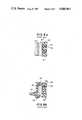
- FIG. 8ais a sectional view of a nozzle cover in accordance with the prior art.
- FIG. 8bis a sectional view of another nozzle cover in accordance with the prior art.
- FIG. 8aillustrates a print head 101 and a nozzle cover 102 of a printer in accordance with the prior art.
- Nozzle cover 102is a plate member having a substantially planar front surface 103 formed of an elastic material. The plate member abuts a nozzle 95 when the printer is not operational. Accordingly, ink evaporation does not occur.
- Print head 101is not fully satisfactory since ink 94 in nozzle 95 flows inward during non-injection due to surface tension. As a result, a small amount of air 93 remains at the tip of nozzle 95. If air pressure increases, the pressure of air 93 pushes ink 94 further inward and away from the tip of nozzle 95. If the printer is then activated, ink will not properly eject.
- cap member 105may be used.
- Cap member 105is formed with a cup-shapd base 99 with a recess on one surface for receiving a gasket 100.
- Gasket 100is also cup-shaped and defines a chamber 96 when cap member 105 abuts a nozzle 106.
- a passage 97is formed through gasket 100 and base 99 to communicate with a negative pressure generating device. If the negative pressure device is activated prior to the start of printing, ink 104 is forced outward toward the tip of nozzle 106 which causes excess ink to be ejected from nozzle 106.
- this type of cap memberis also not fully satisfactory.
- cap member 105When cap member 105 abuts nozzle 106 of the print head, while the print head is not operational air pressure in chamber 96 will increase if the temperature rises. As before, ink 104 at the tip of nozzle 106 is pushed further inward away from the nozzle opening in nozzle 106.
- FIG. 1illustrates an ink-on-demand type ink-jet-printer 10 in accordance with the invention.
- Printer 10includes a print head 14 mounted on top of a carriage 11 and an ink supply tank 18. Carriage 11 moves slidably along a pair of guide members 12 in response to operation of a pulley 21.
- Print head 14is formed with at least one nozzle for ejecting ink. Ink is stored in supply tank 18 and is supplied to print head 14 by an ink supply tube 20 as print head 14 moves transversely across a print paper 19 when pulley 21 is operational so that ink may be ejected at various positions along paper 19.
- Paper 19is disposed about a platen 13 which rotates about a shaft 22 in response to a rotational force applied thereto.
- a nozzle cover 15is pivotably attached to a rotary shaft 17 fitted to an actuator 16. When ink is not being ejected from the nozzle and print head 14 is in the home position, nozzle cover 15 is activated and abuts print head 14.
- FIG. 2illustrates the preferred embodiment of a nozzle cover 35 constructed in accordance with the invention.
- a nozzle cover 35includes a body 32 formed with a base 29 and a side wall 28 defining a recess for receiving a gasket 31.
- Body 32includes a second side wall 27 on the opposite surface which defines an expansion chamber 33.
- Body 32is made of a substantially rigid material, such as synthetic resin.
- Gasket 31is formed with a base 25 and a side wall 26 defining a gasket recess 30.
- Expansion chamber 33communicates with gasket recess 30 through a passage 36 formed in gasket 31 and body 32.
- a diaphragm 34is mounted to second side wall 27 over expansion chamber 33 and is preferably made of nylon or a fluorine resin impermeable to gas.
- nozzle cover 35is shown in operation abuting print head 43 and gakset 31 tightly covers nozzle 38 after printing is completed in response to a position sensor signal.
- a chamber 39is formed between gasket 31 and print head 43. Vapor pressure in chamber 39 quickly reaches saturation so that ink 40 in nozzle 38 does not dry out and nozzle 38 does not clog. If air temperature increases, gas in chamber 39 expands. In response, diaphragm 34 swells outwardly away from body 32 and pressure in chamber 39 remains constant. Therefore, ink 40 is not pushed back to the tank side. If air in chamber 39 contracts due to a temperature drop, diaphragm 37 swells inwardly towards body 32 and pressure in chamber 39 remains constant. Hence, ink does not leak from nozzle 38.
- FIG. 4illustrates a second embodiment of a nozzle cover assembly 46 constructed in accordance with the invention.
- Nozzle cover assembly 46includes a nozzle cover 49 and an expansion chamber 57 communicating therewith.
- Nozzle cover 49includes a body 52 formed with a base 44 and a side wall 45 defining a recess for receiving a gasket 51.
- Gasket 51is formed with a base and a side wall as previously described in connection with the embodiment of FIG. 2 for defining a recess 50.
- a passage 56is formed through gasket 51 and body 52.
- Expansion chamber 57includes a cup-shaped base 58 formed with a rim 48 for defining a recess 53 with a diaphragm 54 mounted thereon.
- Base 58is formed with a passage 59 for communicating with gasket recess 50 by a tube 55. This construction is advantageous since nozzle cover 49 may be increased or decreased in size depending on the head size. Additionally, the size of expansion chamber 57 may be varied as needed.
- FIG. 5illustrates a third embodiment of a nozzle cover assembly 69 constructed in accordance with the invention.
- Nozzle cover assembly 69includes a nozzle cover 65 and an expansion chamber 67.
- Nozzle cover 65includes a body 62, a gasket 61 defining a gasket recess 60 and a passage 66 as previously described in connection with the embodiment of FIG. 4.
- Expansion chamber 67is formed with a base 71 defining a recess 72 with a diaphragm 68 disposed over recess 72. Expansion chamber 67 communicates with gakset recess 60 by a tube 64. Diaphragm 68 flexes to allow air within recess 72 to expand or contract in order to equalize pressure within recess 60.
- Base 71is formed with an exit opening 70 which is connected to a suction device by a pipe 63.
- diaphragm 68swells outwardly from base 71 so that air pressure in recess 60 does not increase. If the suction device is activated, ink is forcedly sucked out. This eliminates clogging in a print head which has not been used for a very long time.
- Nozzle cover assembly 75includes a body 76 formed with a recess on one surface for receiving a gasket 74.
- Gasket 74includes a side wall 73 defining a gasket recess 80.
- a passage 77 as previously described in the earlier embodimentsis formed through gasket 74 and body 76.
- a length of tubing 78is mounted onto the opposed surface of body portion 76 and is coupled to recess 80 at passage 77.
- Tubing 78leads to opening 79 which empties into the air.
- Tubing 78is arranged in a zig-zag pattern to allow increased length over a small surface.
- Tubing 78is all or partially formed of a capillary tube.
- gas in gasket recess 80which has expanded due to a temperature increase is discharged through tubing 78.
- Ink on the tip of a nozzle covered by nozzle cover assembly 75will not dry and clog the nozzle since tubing 78 is long and capillary enough so that the ink solvent vapor makes almost no movement.
- FIG. 7illustrates a fifth embodiment of a nozzle cover assembly 83 constructed in accordance with the invention.
- Nozzle cover assembly 83includes a nozzle cover 84 having a body 88 formed with a base and side wall 81 for defining a recess for receiving a gasket 87 therein.
- Gasket 87is formed with a base and a side wall 82 for defining a gasket chamber 87a.
- Two passages 86a and 86bare formed through gasket 87 and body 88.
- Nozzle cover 84is shown covering a nozzle 85 housing ink 90 as described in connection with FIG. 3.
- a check valve 92communicates with chamber 87a by a tube 91a and a suction device is coupled to chamber 87a by a tube 91b.
- check valve 92When check valve 92 is opened, air pressure in chamber 87a is regulated by the atmosphere and the suction device.
- check valve 92When check valve 92 is closed, the air pressure is regulated by the suction device.
- a nozzle cover assembly in accordance with the inventionreduces ink evaporation in a print head and thereby prevents nozzle clogging. Furthermore, air pressure in the chamber formed between the nozzle cover assembly and the nozzle is maintained at a substantially constant value so that ink remains in the nozzle tip for later ejection.
- inkmay be forcedly drawn to the tip of the nozzle by the use of a suction device connected to the nozzle cover assembly.
Landscapes
- Ink Jet (AREA)
Abstract
Description
Claims (23)
Applications Claiming Priority (4)
| Application Number | Priority Date | Filing Date | Title |
|---|---|---|---|
| JP59117712AJPS60260341A (en) | 1984-06-08 | 1984-06-08 | Ink jet printer |
| JP59-117712 | 1984-06-08 | ||
| JP60-53054 | 1985-03-15 | ||
| JP60053054AJPS61211046A (en) | 1985-03-15 | 1985-03-15 | Ink jet printer |
Publications (1)
| Publication Number | Publication Date |
|---|---|
| US4684963Atrue US4684963A (en) | 1987-08-04 |
Family
ID=26393763
Family Applications (1)
| Application Number | Title | Priority Date | Filing Date |
|---|---|---|---|
| US06/742,503Expired - LifetimeUS4684963A (en) | 1984-06-08 | 1985-06-07 | Nozzle cover assembly for an ink-on-demand type ink jet printer |
Country Status (1)
| Country | Link |
|---|---|
| US (1) | US4684963A (en) |
Cited By (22)
| Publication number | Priority date | Publication date | Assignee | Title |
|---|---|---|---|---|
| EP0317267A3 (en)* | 1987-11-17 | 1989-11-15 | Canon Kabushiki Kaisha | Ink jet recording apparatus and discharge recovery device used with the same |
| US5027134A (en)* | 1989-09-01 | 1991-06-25 | Hewlett-Packard Company | Non-clogging cap and service station for ink-jet printheads |
| US5055856A (en)* | 1988-09-07 | 1991-10-08 | Seiko Epson Corporation | Capping device for ink jet printers |
| US5146243A (en)* | 1991-07-29 | 1992-09-08 | Hewlett-Packard Company | Diaphragm cap system for ink-jet printers |
| US5216449A (en)* | 1991-07-29 | 1993-06-01 | Hewlett-Packard Company | Rounded capillary vent system for ink-jet printers |
| US5252993A (en)* | 1988-09-07 | 1993-10-12 | Seiko Epson Corporation | Capping apparatus for an ink jet printer |
| US5311214A (en)* | 1985-11-08 | 1994-05-10 | Canon Kabushiki Kaisha | Ink jet recording apparatus having means for removing foreign material from an ink supply path by first introducing an into the ink supply path |
| US5394178A (en)* | 1992-12-21 | 1995-02-28 | Hewlett-Packard Company | Printhead servicing apparatus with pivotal servicing lever |
| US5455609A (en)* | 1992-09-30 | 1995-10-03 | Hewlett-Packard Company | Printhead servicing station for printers |
| US5572245A (en)* | 1994-03-10 | 1996-11-05 | Hewlett-Packard Company | Protective cover apparatus for an ink-jet pen |
| US5659341A (en)* | 1994-04-26 | 1997-08-19 | Hewlett-Packard Company | Adjustable position reference lever for a wiper assembly in an ink-jet printer |
| US5682186A (en)* | 1994-03-10 | 1997-10-28 | Hewlett-Packard Company | Protective capping apparatus for an ink-jet pen |
| US5883648A (en)* | 1995-06-19 | 1999-03-16 | Francotyp-Postalia Ag & Co. | Arrangement for keeping the nozzles of an ink print head clean |
| US6042215A (en)* | 1996-09-04 | 2000-03-28 | Brother Kogyo Kabushiki Kaisha | Capping device and printer including the same |
| US6074037A (en)* | 1996-11-15 | 2000-06-13 | Brother Kogyo Kabushiki Kaisha | Print head capping device |
| US6378980B1 (en) | 2000-05-18 | 2002-04-30 | Samsung Electronics Co., Ltd. | Printer capable of preventing drying of nozzle and control method thereof |
| US6406124B1 (en)* | 2000-01-31 | 2002-06-18 | Hewlett-Packard Company | Ganged inkjet printhead capping system |
| US20050110827A1 (en)* | 2003-11-21 | 2005-05-26 | Aldrich Charles S. | Printhead cap assembly for an ink jet printer |
| US20070139493A1 (en)* | 2005-12-21 | 2007-06-21 | Lexmark International, Inc. | Shipping reservoirs for inkjet printheads, and assemblies including the same |
| US20070229581A1 (en)* | 2006-03-31 | 2007-10-04 | Brother Kogyo Kabushiki Kaisha | Ink-Jet Head |
| US20070257957A1 (en)* | 2006-03-31 | 2007-11-08 | Osamu Takagi | Ink-jet recording apparatus and cap |
| US20080284814A1 (en)* | 2006-09-25 | 2008-11-20 | Brother Kogyo Kabushiki Kaisha | Cap and ink-jet head protection assembly |
Citations (5)
| Publication number | Priority date | Publication date | Assignee | Title |
|---|---|---|---|---|
| US3930260A (en)* | 1973-05-09 | 1975-12-30 | Olympia Werke Ag | Apparatus for applying a liquid in droplets to a surface |
| US4015272A (en)* | 1974-08-14 | 1977-03-29 | Matsushita Electric Industrial Co., Ltd. | Ink ejection type writing unit |
| US4124853A (en)* | 1975-09-29 | 1978-11-07 | Siemens Aktiengesellschaft | Hydraulic dampening device in an ink supply system of an ink operated mosaic printer unit |
| US4417259A (en)* | 1981-02-04 | 1983-11-22 | Sanyo Denki Kabushiki Kaisha | Method of preventing ink clogging in ink droplet projecting device, an ink droplet projecting device, and an ink jet printer |
| US4533927A (en)* | 1982-05-06 | 1985-08-06 | Sharp Kabushiki Kaisha | Capping mechanism for preventing nozzle blocking in an ink jet system printer |
- 1985
- 1985-06-07USUS06/742,503patent/US4684963A/ennot_activeExpired - Lifetime
Patent Citations (5)
| Publication number | Priority date | Publication date | Assignee | Title |
|---|---|---|---|---|
| US3930260A (en)* | 1973-05-09 | 1975-12-30 | Olympia Werke Ag | Apparatus for applying a liquid in droplets to a surface |
| US4015272A (en)* | 1974-08-14 | 1977-03-29 | Matsushita Electric Industrial Co., Ltd. | Ink ejection type writing unit |
| US4124853A (en)* | 1975-09-29 | 1978-11-07 | Siemens Aktiengesellschaft | Hydraulic dampening device in an ink supply system of an ink operated mosaic printer unit |
| US4417259A (en)* | 1981-02-04 | 1983-11-22 | Sanyo Denki Kabushiki Kaisha | Method of preventing ink clogging in ink droplet projecting device, an ink droplet projecting device, and an ink jet printer |
| US4533927A (en)* | 1982-05-06 | 1985-08-06 | Sharp Kabushiki Kaisha | Capping mechanism for preventing nozzle blocking in an ink jet system printer |
Cited By (30)
| Publication number | Priority date | Publication date | Assignee | Title |
|---|---|---|---|---|
| US6196655B1 (en)* | 1985-11-08 | 2001-03-06 | Canon Kabushiki Kaisha | Ink-jet recording apparatus and recovery process method of the same |
| US5311214A (en)* | 1985-11-08 | 1994-05-10 | Canon Kabushiki Kaisha | Ink jet recording apparatus having means for removing foreign material from an ink supply path by first introducing an into the ink supply path |
| US4952947A (en)* | 1987-11-17 | 1990-08-28 | Canon Kabushiki Kaisha | Ink discharge recovery device having at least one suction-applying conduit located at a particular position in a capping member and an ink jet recording apparatus incorporating the device |
| EP0317267A3 (en)* | 1987-11-17 | 1989-11-15 | Canon Kabushiki Kaisha | Ink jet recording apparatus and discharge recovery device used with the same |
| US5252993A (en)* | 1988-09-07 | 1993-10-12 | Seiko Epson Corporation | Capping apparatus for an ink jet printer |
| US5055856A (en)* | 1988-09-07 | 1991-10-08 | Seiko Epson Corporation | Capping device for ink jet printers |
| US5027134A (en)* | 1989-09-01 | 1991-06-25 | Hewlett-Packard Company | Non-clogging cap and service station for ink-jet printheads |
| US5216449A (en)* | 1991-07-29 | 1993-06-01 | Hewlett-Packard Company | Rounded capillary vent system for ink-jet printers |
| EP0526010A3 (en)* | 1991-07-29 | 1993-05-26 | Hewlett-Packard Company | Diaphragm cap system for ink-jet printers |
| US5517220A (en)* | 1991-07-29 | 1996-05-14 | Hewlett-Packard Company | Rounded capillary vent system for ink-jet printers |
| US5146243A (en)* | 1991-07-29 | 1992-09-08 | Hewlett-Packard Company | Diaphragm cap system for ink-jet printers |
| US5455609A (en)* | 1992-09-30 | 1995-10-03 | Hewlett-Packard Company | Printhead servicing station for printers |
| US5394178A (en)* | 1992-12-21 | 1995-02-28 | Hewlett-Packard Company | Printhead servicing apparatus with pivotal servicing lever |
| US5682186A (en)* | 1994-03-10 | 1997-10-28 | Hewlett-Packard Company | Protective capping apparatus for an ink-jet pen |
| US5572245A (en)* | 1994-03-10 | 1996-11-05 | Hewlett-Packard Company | Protective cover apparatus for an ink-jet pen |
| US5659341A (en)* | 1994-04-26 | 1997-08-19 | Hewlett-Packard Company | Adjustable position reference lever for a wiper assembly in an ink-jet printer |
| US5883648A (en)* | 1995-06-19 | 1999-03-16 | Francotyp-Postalia Ag & Co. | Arrangement for keeping the nozzles of an ink print head clean |
| US6042215A (en)* | 1996-09-04 | 2000-03-28 | Brother Kogyo Kabushiki Kaisha | Capping device and printer including the same |
| US6074037A (en)* | 1996-11-15 | 2000-06-13 | Brother Kogyo Kabushiki Kaisha | Print head capping device |
| US6406124B1 (en)* | 2000-01-31 | 2002-06-18 | Hewlett-Packard Company | Ganged inkjet printhead capping system |
| US6378980B1 (en) | 2000-05-18 | 2002-04-30 | Samsung Electronics Co., Ltd. | Printer capable of preventing drying of nozzle and control method thereof |
| US7021741B2 (en) | 2003-11-21 | 2006-04-04 | Lexmark International, Inc. | Printhead cap assembly for an ink jet printer |
| US20050110827A1 (en)* | 2003-11-21 | 2005-05-26 | Aldrich Charles S. | Printhead cap assembly for an ink jet printer |
| US20070139493A1 (en)* | 2005-12-21 | 2007-06-21 | Lexmark International, Inc. | Shipping reservoirs for inkjet printheads, and assemblies including the same |
| US20070229581A1 (en)* | 2006-03-31 | 2007-10-04 | Brother Kogyo Kabushiki Kaisha | Ink-Jet Head |
| US20070257957A1 (en)* | 2006-03-31 | 2007-11-08 | Osamu Takagi | Ink-jet recording apparatus and cap |
| US7690756B2 (en)* | 2006-03-31 | 2010-04-06 | Brother Kogyo Kabushiki Kaisha | Ink-jet recording apparatus and cap |
| US7806504B2 (en) | 2006-03-31 | 2010-10-05 | Brother Kogyo Kabushiki Kaisha | Ink-jet head protection assembly and protection method of an ink-jet head |
| US20080284814A1 (en)* | 2006-09-25 | 2008-11-20 | Brother Kogyo Kabushiki Kaisha | Cap and ink-jet head protection assembly |
| US8162434B2 (en) | 2006-09-25 | 2012-04-24 | Brother Kogyo Kabushiki Kaisha | Cap and ink-jet head protection assembly |
Similar Documents
| Publication | Publication Date | Title |
|---|---|---|
| US4684963A (en) | Nozzle cover assembly for an ink-on-demand type ink jet printer | |
| US6854836B2 (en) | Liquid container, liquid supply system, liquid using apparatus, ink tank, ink supply system, inkjet print head and print apparatus | |
| US5825387A (en) | Ink supply for an ink-jet printer | |
| US6193364B1 (en) | Ink cartridge for ink jet printer | |
| US5646666A (en) | Back pressure control in ink-jet printing | |
| US6145973A (en) | Ink-jet cartridge | |
| US6186620B1 (en) | Ink pressure control apparatus for ink-jet pens | |
| US6722763B1 (en) | Inkjet pen and pressure control device thereof | |
| AU2003200496A1 (en) | Ink Cartridge and Method of Regulating Fluid Flow | |
| US6139137A (en) | Bottom fill inkjet cartridge through bubble generator | |
| US5946015A (en) | Method and apparatus for air removal from ink jet printheads | |
| JPH05124214A (en) | Inkjet recording device | |
| CA1250485A (en) | Nozzle cleaning device for an ink jet system printer | |
| JP2009023108A (en) | Liquid storage container, recording head, and ink jet recording apparatus | |
| JP2002086721A (en) | Ink jet recording device | |
| JP3622880B2 (en) | ink cartridge | |
| JPS6319151Y2 (en) | ||
| JP2582741Y2 (en) | Inkjet printer head | |
| JPH06115092A (en) | Inkjet recording head | |
| JPS61211046A (en) | Ink jet printer | |
| US6692120B2 (en) | Pressure regulation apparatus for ink reservoir | |
| JPS5910309B2 (en) | Device to prevent clogging of ink jet nozzles in inkjet printers | |
| JPS6130854Y2 (en) | ||
| JP2001071536A (en) | Ink jet recording device | |
| JP2709514B2 (en) | Liquid jet recording unit |
Legal Events
| Date | Code | Title | Description |
|---|---|---|---|
| AS | Assignment | Owner name:EPSON CORPORATION, 4-1, 2-CHOME NISHISHINJUKU, SHI Free format text:ASSIGNMENT OF ASSIGNORS INTEREST.;ASSIGNOR:NAKA, TAKAHIRO;REEL/FRAME:004416/0809 Effective date:19850604 Owner name:EPSON CORPORATION, A COMPANY OF JAPAN,JAPAN Free format text:ASSIGNMENT OF ASSIGNORS INTEREST;ASSIGNOR:NAKA, TAKAHIRO;REEL/FRAME:004416/0809 Effective date:19850604 | |
| STCF | Information on status: patent grant | Free format text:PATENTED CASE | |
| FEPP | Fee payment procedure | Free format text:PAYOR NUMBER ASSIGNED (ORIGINAL EVENT CODE: ASPN); ENTITY STATUS OF PATENT OWNER: LARGE ENTITY | |
| FPAY | Fee payment | Year of fee payment:4 | |
| FEPP | Fee payment procedure | Free format text:PAYOR NUMBER ASSIGNED (ORIGINAL EVENT CODE: ASPN); ENTITY STATUS OF PATENT OWNER: LARGE ENTITY Free format text:PAYER NUMBER DE-ASSIGNED (ORIGINAL EVENT CODE: RMPN); ENTITY STATUS OF PATENT OWNER: LARGE ENTITY | |
| FPAY | Fee payment | Year of fee payment:8 | |
| FPAY | Fee payment | Year of fee payment:12 |