US4684081A - Multifunction power system for an aircraft - Google Patents
Multifunction power system for an aircraftDownload PDFInfo
- Publication number
- US4684081A US4684081AUS06/873,026US87302686AUS4684081AUS 4684081 AUS4684081 AUS 4684081AUS 87302686 AUS87302686 AUS 87302686AUS 4684081 AUS4684081 AUS 4684081A
- Authority
- US
- United States
- Prior art keywords
- duct assembly
- coupled
- leg
- turbine
- duct
- Prior art date
- Legal status (The legal status is an assumption and is not a legal conclusion. Google has not performed a legal analysis and makes no representation as to the accuracy of the status listed.)
- Expired - Lifetime
Links
- 230000008878couplingEffects0.000claimsdescription6
- 238000010168coupling processMethods0.000claimsdescription6
- 238000005859coupling reactionMethods0.000claimsdescription6
- 230000000712assemblyEffects0.000claimsdescription5
- 238000000429assemblyMethods0.000claimsdescription5
- 230000001143conditioned effectEffects0.000claimsdescription5
- 238000011144upstream manufacturingMethods0.000claimsdescription2
- 230000007613environmental effectEffects0.000abstractdescription6
- 238000001816coolingMethods0.000description25
- 239000000446fuelSubstances0.000description11
- 230000001276controlling effectEffects0.000description9
- 239000007789gasSubstances0.000description6
- 238000012423maintenanceMethods0.000description5
- 230000009467reductionEffects0.000description4
- 230000008901benefitEffects0.000description3
- 238000002485combustion reactionMethods0.000description3
- 230000010354integrationEffects0.000description3
- 239000007858starting materialSubstances0.000description3
- 238000000034methodMethods0.000description2
- 238000004378air conditioningMethods0.000description1
- 230000006698inductionEffects0.000description1
- 238000012986modificationMethods0.000description1
- 230000004048modificationEffects0.000description1
- 230000008520organizationEffects0.000description1
- 239000003380propellantSubstances0.000description1
- 230000001105regulatory effectEffects0.000description1
- 230000010076replicationEffects0.000description1
Images


Classifications
- B—PERFORMING OPERATIONS; TRANSPORTING
- B64—AIRCRAFT; AVIATION; COSMONAUTICS
- B64D—EQUIPMENT FOR FITTING IN OR TO AIRCRAFT; FLIGHT SUITS; PARACHUTES; ARRANGEMENT OR MOUNTING OF POWER PLANTS OR PROPULSION TRANSMISSIONS IN AIRCRAFT
- B64D41/00—Power installations for auxiliary purposes
- B—PERFORMING OPERATIONS; TRANSPORTING
- B64—AIRCRAFT; AVIATION; COSMONAUTICS
- B64D—EQUIPMENT FOR FITTING IN OR TO AIRCRAFT; FLIGHT SUITS; PARACHUTES; ARRANGEMENT OR MOUNTING OF POWER PLANTS OR PROPULSION TRANSMISSIONS IN AIRCRAFT
- B64D13/00—Arrangements or adaptations of air-treatment apparatus for aircraft crew or passengers, or freight space
- B64D13/06—Arrangements or adaptations of air-treatment apparatus for aircraft crew or passengers, or freight space the air being conditioned
- B64D2013/0603—Environmental Control Systems
- B64D2013/0696—Environmental Control Systems with provisions for starting power plants
- F—MECHANICAL ENGINEERING; LIGHTING; HEATING; WEAPONS; BLASTING
- F05—INDEXING SCHEMES RELATING TO ENGINES OR PUMPS IN VARIOUS SUBCLASSES OF CLASSES F01-F04
- F05B—INDEXING SCHEME RELATING TO WIND, SPRING, WEIGHT, INERTIA OR LIKE MOTORS, TO MACHINES OR ENGINES FOR LIQUIDS COVERED BY SUBCLASSES F03B, F03D AND F03G
- F05B2220/00—Application
- F05B2220/50—Application for auxiliary power units (APU's)
- Y—GENERAL TAGGING OF NEW TECHNOLOGICAL DEVELOPMENTS; GENERAL TAGGING OF CROSS-SECTIONAL TECHNOLOGIES SPANNING OVER SEVERAL SECTIONS OF THE IPC; TECHNICAL SUBJECTS COVERED BY FORMER USPC CROSS-REFERENCE ART COLLECTIONS [XRACs] AND DIGESTS
- Y02—TECHNOLOGIES OR APPLICATIONS FOR MITIGATION OR ADAPTATION AGAINST CLIMATE CHANGE
- Y02T—CLIMATE CHANGE MITIGATION TECHNOLOGIES RELATED TO TRANSPORTATION
- Y02T50/00—Aeronautics or air transport
- Y02T50/40—Weight reduction
- Y—GENERAL TAGGING OF NEW TECHNOLOGICAL DEVELOPMENTS; GENERAL TAGGING OF CROSS-SECTIONAL TECHNOLOGIES SPANNING OVER SEVERAL SECTIONS OF THE IPC; TECHNICAL SUBJECTS COVERED BY FORMER USPC CROSS-REFERENCE ART COLLECTIONS [XRACs] AND DIGESTS
- Y10—TECHNICAL SUBJECTS COVERED BY FORMER USPC
- Y10S—TECHNICAL SUBJECTS COVERED BY FORMER USPC CROSS-REFERENCE ART COLLECTIONS [XRACs] AND DIGESTS
- Y10S62/00—Refrigeration
- Y10S62/05—Aircraft cooling
Definitions
- the inventionrelates to the field of secondary power systems for an aircraft and, in particular, to an integrated auxiliary power unit, environmental control system, engine start system, and emergency power system for an aircraft.
- the APUis considered by the airlines and the military to be a low-utilization device that adds weight, complexion, and maintenance support to the airplane; also, it is considered as one that has little operational benefit during most flight conditions.
- the APUis not a welcome addition to the airplane; but, it is one that is essential thereto when independence of ground support power for engine starting, environmental control, and electrical power functions is necessary.
- the APU systemis inevitable.
- Typical military aircraftuse airframe mounted accessory drives (AMAD) mechanically coupled to the main engines for driving hydraulic pumps, electric generators, and other accessories.
- a separate EPUis then often provided which uses either a pressurized air bottle or mono/bi-propellant fuel to drive an air turbine motor inlet coupled to a generator and hydraulic pumps for emergency flight loads.
- the main APUitself is normally a ground-use unit which drives an electric generator, hydraulic pumps, and typically an air compressor to supply pressurized air for air conditioning and avionic cooling loads.
- auxiliary power unitintegrates the auxiliary power unit, the environmental control system, the emergency power unit, and the engine start system so as to improve reliability, reduce parts duplication, minimize maintenance support, and finally to reduce the size and weight of the aircraft.
- the inventionis a secondary power system for an aircraft wherein the functions of the auxiliary power unit, environmental control system, engine start system, and emergency power unit are all integrated to provide an overall reduction in components.
- the inventionincludes a compressor means having an inlet coupled to the exterior of the aircraft and which is connected by a drive shaft to a first turbine.
- the compressor meanscomprises first and second variable inlet guide vane compressors in series with a by-passable heat exchanger mounted therebetween.
- an electric motor and a starter-generator(functioning dually as a motor and a generator) are connected to the same drive shaft.
- the systemincorporates a first duct assembly having a first end coupled to the outlet of the compressor means and a second end which is bifurcated with one leg coupled overboard and the other leg coupled to the compartments on board the aircraft requiring conditioned air.
- the first duct assemblycouples a first outside air-cooled heat exchanger means, a first combustor, and a second turbine (isolated from the first turbine) in series and, additionally, includes a second outside air-cooled heat exchanger means mounted in the second leg thereof.
- the second turbineis coupled by a drive shaft to a generator and, additionally, to the engine via a clutch.
- the systemfurther includes second and third duct assemblies.
- the second duct assemblyalso has a first end connected to the outlet of the compressor means and a bifurcated second end with a first leg thereof connected to the first duct assembly and a second leg coupled overboard.
- This second duct assemblycouples a second combustor and the first turbine in series.
- An auxiliary pressurized air supplyis also coupled thereto.
- the third duct assemblyhas a first end connected to the compartments and a second end having a first leg coupled to the first duct assembly downstream of the first combustor, a second leg coupled to the second duct assembly downstream of the second combustor, and a third leg coupled overboard.
- valve meansare incorporated into the system to control the flow path of air and combustion products which include: (1) A first control valve means for controlling the flow from the outlet of the compressor means to the first and second duct assemblies; (2) a second control valve means mounted in the first duct assembly for controlling the flow to first and second legs thereof; (3) a third control valve means coupled to the second duct assembly for controlling flow to and between the first and second legs thereof; (4) a fourth control valve means for controlling the flow in the first duct assembly from the first leg of the third duct assembly; (5) a fifth control valve means for controlling the flow from the second duct assembly and from the second leg of the third duct assembly; and finally, (6) a sixth control valve means for controlling the flow in the third leg of the third duct assembly.
- the systemessentially has five modes of operation.
- the starter-generatorin the starter mode is used to bring the compressor means and first turbine up to a speed wherein combustion of fuel in the second combustor is effected and the compressor means and first turbine are brought up to full operating speed.
- the starter-generatoris switched to the generator mode and furnishes electrical power to the aircraft for checkout purposes.
- the exhaust gases from the first turbineare ducted by the third control valve means overload via the second leg of the second duct assembly.
- Air from the compressor meansis now additionally ducted to the first duct assembly through the first heat exchanger means for cooling and then through to the second turbine where it is also cooled, i.e., the second turbine absorbs energy and is loaded by the generator coupled thereto.
- the airis passed through the second heat exchanger means in the first leg of the first duct assembly where it is further cooled and finally into the various compartments requiring cooling. Return flow from the compartments is directed overboard through the third duct assembly (third leg).
- the generator powered by the second turbineprovides some or all of the electrical power.
- the motor(powered by engine driving generators) is now used to drive the compressor means and first turbine.
- the heat exchanger means between the first and second compressorsis used to cool the output air from the first compressor.
- the further compressed output air from the second compressoris passed through the first and second heat exchangers and into the compartments normally bypassing the second turbine.
- some or all of the airmay be directed through the second turbine wherein the air is further cooled.
- Return air from the compartmentsis ducted to the first turbine where it does work thereon prior to being dumped overboard, thus offloading the motor.
- the source of high pressure airis fed to the first combustor along with fuel which is ignited providing hot gas to drive the second turbine which in turn drives the generator.
- the generatoris then coupled to the motor to bring the compressor means and first turbine back up to speed.
- fuelis added to the second combustor and ignited (the first combustor remains in operation but is now fed by the compressor means).
- the starter-generatorin the generator mode) now provides power and the second turbine can now be coupled to the engine to attempt a restart.
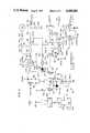
- FIG. 1Illustrated in FIG. 1 is a schematic representation of the multifunction power system shown in the ground start mode.
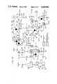
- FIG. 2Illustrated in FIG. 2 is a schematic representation of the multifunction power system in the ground cooling mode.
- FIG. 3Illustrated in FIG. 3 is a schematic representation of the multifunction power system in the engine start mode.
- FIG. 4Illustrated in FIG. 4 is a schematic representation of the multifunction power system in the flight cooling mode.
- FIG. 5Illustrated in FIG. 5 is a schematic representation of the multifunction power system in the emergency power mode.
- FIG. 1Illustrated in FIG. 1 is a schematic representation of the multifunction power system for an aircraft, generally designated by numeral 10, shown in the auxiliary power unit mode.
- the system 10comprises a compressor means 12 coupled to a first turbine 14 by means of a drive shaft 16.
- the compressor means 12includes first and second compressors 20 and 22, respectively, coupled to the drive shaft 16. These compressors are preferably centrifugal type with variable inlet guide vanes.
- the inlet 24 to the first compressor 20is coupled to the exterior of the aircraft and the compressor 22 has an outlet 25.
- the compressors 20 and 22are coupled in series by duct 30 in which is mounted a heat exchanger means 32.
- the heat exchanger means 32includes an air-cooled heat exchanger 34 having an air inlet duct 35A and air outlet duct 35B.
- a bypass duct 36 incorporating a control valve 38couples duct 35A directly to duct 35B bypassing heat exchanger 34.
- the heat exchanger 34uses ram air when the aircraft is at a speed for cooling incoming compressed air from compressor 20, while on the ground a fan 39 is used to draw air therethrough.
- the control valve 38can be modulated to control the degree of cooling effected by the heat exchanger 34. All the subsequent heat exchangers described herein operate in the same manner.
- an AC motor 40(preferably a two-speed, squirrel-cage induction type) electrically coupled by relays 42 and 44 to internal or external power via three-phase AC power lines, respectively. While shown mounted between the two compressors it could be coupled to the drive shaft elsewhere.
- a starter-generator 48which functions dually as a motor and a generator, is coupled to the drive shaft 16 outboard of the compressor 20.
- the starter-generatoris shown in this position for purposes of illustration only and, thus, it could be located in a different location.
- the starter-generatorIn the start mode it is electrically connected to a battery circuit 50, which includes a battery 52, a relay 53, and a three-phase inverter 54. Additionally, the starter-generator can be coupled to internal three-phase circuitry via relay 58 when in the generator mode.
- a duct assembly 66 having a first end 67is coupled to the outlet 25 of the compressor 22 by its first end 67 and has a bifurcated second end 68.
- Mounted in series in the duct assembly 66are a flow modulating control valve 70, a heat exchanger means 72, a check valve 74, a combustor 76, a selector control valve 78, and a second turbine 80.
- the heat exchanger means 72includes an air-cooled heat exchanger 82 having a cooling air inlet duct 83A and a cooling air outlet duct 83B.
- a by-pass duct 84 having a control valve 86 mounted thereincouples duct 83A directly to duct 83B bypassing heat exchanger 82.
- a by-pass duct 90 with a control valve 92 mounted thereinis coupled upstream of the combustor 76 and downstream thereof in order that the combustor 76 may be bypassed in certain modes of operation (to be subsequently discussed).
- the turbine 80can be bypassed by means of a by-pass duct 94 with a modulating control valve 96 mounted therein.
- a pressurizable tank 98is coupled by a line 100, to the duct assembly 66 between the check valve 74 and combustor 76 and incorporates a pressure regulator 101 and a control valve 102 mounted in series therein. As illustrated, it is coupled to the by-pass duct 90 between duct assembly 66 and valve 92.
- the turbine 80is coupled by shaft 81 to an AC generator 106 and thereafter to an engine (not shown) via a clutch 108.
- the generator 106provides electrical power to the aircraft and is controlled by a three-phase relay 110.
- the second end 68 of the duct assembly 66has a first leg 68A which is coupled to the one or more compartments of the aircraft requiring conditioned air and mounts a heat exchanger means 120 and an electrical heater 122 in series therein.
- the heat exchanger means 120includes an outside air-cooled heat exchanger 124 having an inlet duct 126A and an outlet duct 126B.
- a by-pass duct 130having a control valve 132 mounted therein, is coupled at one end to the inlet duct 126A and the other end to the outlet duct 126B, thus allowing cooling air to bypass the heat exchanger 124.
- a second leg 68B of the duct assembly 66is coupled to duct 126A of the heat exchanger means 120.
- a selector control valve 136is used to control the flow between legs 68A and 68B.
- a second duct assembly 140has a first end 141 coupled to the outlet 25 of the compressor 22 and a bifurcated second end 142 and couples a modulating control valve 150, a combustor 152, a selector control valve 154, and the turbine 14 in series.
- the second end 142mounts a selector control valve 160 for controlling the flow to leg 142A which is coupled overboard and leg 142B which is coupled to duct assembly 66 just downstream of turbine 80 via by-pass duct 94.
- a third duct assembly 170 having a first end 171is coupled to the compartments and has a three branch second end 172 comprising a first leg 172A coupled to a selector valve 78, a second leg 172B coupled to selector valve 154, and a third leg 172C', having a control valve 173 mounted therein, coupled overboard.
- control valves 68 and 154not only control the flow in duct assemblies 66 and 140, respectively, but also the return flow from the compartments.
- FIG. 1which, as previously stated, is a schematic representation illustrating the system in the APU ground operation mode.
- the relay 53is closed connecting the starter-generator 48 to the battery 52 via inverter 54.
- the starter-generator 48acts as a starter. This will cause the compressors 20 and 22 and turbine 14 to start up.
- the by-pass valve 38is open allowing the flow to bypass the heat exchanger 34.
- the valve 150is open and valve 154 is positioned to coupled combustor 152 to the turbine 14.
- Valve 160is positioned to couple the output of the turbine 14 overboard via leg 142A of the duct 140.
- FIG. 2is a schematic representation of the system in a ground cooling mode, it can be seen that the system is still operating in the ground APU mode; but, more fuel is added to the combustor 152, increasing the output from the compressor means 12.
- the heat exchanger means 34is in operation and is used to cool the output air from compressor 20.
- the by-pass valve 38is used to regulate the amount of cooling by controlling the amount of air bypassing the heat exchanger 34 through duct 36.
- Valve 70is brought into operation to modulate the flow of air to duct assembly 66.
- the amount of cooling by the heat exchanger 82is controlled by the position of by-pass valve 86 in duct 84.
- Valve 92 in by-pass duct 90is opened allowing the air to bypass the combustor 76.
- the combustor 76is bypassed to prevent any residue fuel or combustion air products therein from reaching the compartments.
- Valve 78is set to direct the pressurized flow to the turbine 80 with flow therethrough controlled by valve 96 in by-pass duct 94.
- Valve 136is set to direct the flow from the turbine 80 through leg 68A including heat exchanger means 124 to the compartments requiring the conditioned air.
- Air passing through the turbine 80is further cooled by absorbing energy therefrom.
- the energy absorbed by the turbineis used to drive generator 106 providing some or all the electrical power (relay 110 is closed coupling the generator 106 to the aircraft's electrical circuits).
- the airthen passes through heat exchanger 124, where it is further cooled and then into the compartments.
- the amount of cooling by heat exchanger 120is controlled by valve 132 in by-pass duct 130.
- Return air from the compartmentsis ducted overboard via leg 172C' of duct assembly 170, i.e., valve 173 is open.
- great leewayis provided in optimizing the temperature of incoming air to the compartments by modulating the air flow through heat exchanger means 32, 72, and 120 and also controlling the bypass air around turbine 80, via by-pass duct 94 and valve 96.
- FIG. 3is a schematic representation of the system in the engine start mode, to start the engines with the system in the configuration illustrated in FIG. 2, fuel is added to combustor 76 which is ignited. Also note that, incoming air to heat exchanger 34 between the two compressors is now also bypassed since no cooling of the compartments is contemplated during engine start.
- Generator 106is disconnected via relay 110 and the clutch 108 is engaged coupling the turbine 80 to the engine for starting.
- Valve 96 in by-pass duct 96is closed, directing all the hot gases to the turbine 80. Air exiting the turbine 80 is directed by valve 136 to second leg 68B of duct assembly 66, to by-pass duct 130 (valve 132 is in the open position). In this mode, with both combustors 76 and 152 producing hot gas, the electrical power to the aircraft is provided by starter-generator 48.
- FIG. 4is a schematic representation of the system in the flight cooling mode, it can be seen that with the engines running, relay 44 is closed, coupling the motor 40 to electrical power from engine driven generators (not shown) which in turn drives the starter-generator 48 (operating in the generator mode), compressors 20 and 22, and turbine 14.
- the heat exchanger means 32is in use as well as both heat exchanger means 72 and 120.
- Valve 70is used to modulate flow in duct assembly 66 (valve 150 in duct 140 is closed).
- the combustor 76is bypassed by opening valve 92 in by-pass duct 90.
- Valve 78is positioned to direct air to the turbine 80 wherein further cooling takes place because of the expansion of the air through the turbine.
- Flow through the turbine 80is modulated by valve 96.
- the generator 106can be put on-line to load the turbine 80 by closing relay 110 if the turbine 80 is used for cooling. Thereafter, the air is directed by valve 136 through heat exchanger means 124 to the compartments. Return air passes through leg 172B of duct assembly 170 and is directed through turbine 14 via valve 154 and thereafter overboard. Thus, the return air expands through the turbine 14 producing power and reducing the load on the motor 40.
- the heater 122can be brought on-line to heat the air entering the compartments when the aircraft is at high altitude and the outside air is extremely cold. With the heater 122 on the heat exchangers means 32, 72, and 120 are normally inoperative.
- FIG. 5is a schematic representation of the system in the emergency power mode, and assuming that the system is in the flight cooling mode as illustrated in FIG. 4, the loss of engine power will deprive motor 40 of electrical power.
- the compressors 20 and 22 and turbine 14will immediately start to slow down.
- valve 102is opened allowing pressurized air from bottle 98 regulated by pressure regulator 101, to pass into duct assembly 66 downstream of check valve 74 and into combustor 76.
- the check valve 74prevents flow toward the compressor means 12.
- Fuelis added to the combustor 76 and ignited.
- the valve 78is set to direct the hot gas to turbine 80 (by-pass valve 96 is closed), and the generator 106 is brought up to speed.
- the output from generator 106(relay 110 is closed) is then used to power systems necessary to control the aircraft so that it can be brought down from altitude and landed with power.
- the electrical power from the generator 106can be fed to motor 40 to bring the compressors 20 and 22 and turbine 14 back up to speed.
- combustor 152can be brought back on-line.
- the aircraftcan be switched back into the ground APU mode as illustrated in FIG. 1 and, thereafter, the engine start procedure, as previously outlined, can be initiated.
- the batterycan be used to power the starter-generator 48 (in the starter mode) to bring the compressors 20 and 22 and turbine 14 back up to speed.
- the inventionhas applicability on aircraft and in particular on aircraft using electrically operated secondary power systems.
Landscapes
- Engineering & Computer Science (AREA)
- Aviation & Aerospace Engineering (AREA)
- Health & Medical Sciences (AREA)
- General Health & Medical Sciences (AREA)
- Pulmonology (AREA)
- Control Of Turbines (AREA)
Abstract
Description
The invention relates to the field of secondary power systems for an aircraft and, in particular, to an integrated auxiliary power unit, environmental control system, engine start system, and emergency power system for an aircraft.
In modern high-speed aircraft, weight, space, and costs are highly important. Also, there is a heavy emphasis on the reliability and maintenance support aspects of the systems in these aircrafts since the reliability and maintenance impacts strongly on the availability and sortie rates of aircraft. Pursuant to this, a reduction of part counts and a reduction in complexity are key to the achievement of the high-reliability and low-maintenance criteria. Thus, the integration of the auxiliary power unit (APU), emergency power unit (EPU), environmental control system (ECS), and engine start system (ESS) with a correspondent reduction in the number of parts, weight and size is highly desirable. This is particularly true in that the APU is considered by the airlines and the military to be a low-utilization device that adds weight, complexion, and maintenance support to the airplane; also, it is considered as one that has little operational benefit during most flight conditions. For these reasons, the APU is not a welcome addition to the airplane; but, it is one that is essential thereto when independence of ground support power for engine starting, environmental control, and electrical power functions is necessary. Certainly in any advanced fighter-type aircraft which is subject to bare site dispersal and has to scramble rapidly, the APU system is inevitable.
The complexity of such elements of the secondary systems are readily apparent when viewing the prior art. Typical military aircraft use airframe mounted accessory drives (AMAD) mechanically coupled to the main engines for driving hydraulic pumps, electric generators, and other accessories. A separate EPU is then often provided which uses either a pressurized air bottle or mono/bi-propellant fuel to drive an air turbine motor inlet coupled to a generator and hydraulic pumps for emergency flight loads. The main APU itself is normally a ground-use unit which drives an electric generator, hydraulic pumps, and typically an air compressor to supply pressurized air for air conditioning and avionic cooling loads.
Some prior efforts have been made to integrate the functions of the APU and EPU to maximize the role of the various components thereof, as they have met some degree of success. An additional advantage offered by such integration is that a single-type energy power source such as aviation fuel could be used for the EPU as well as the APU. However, the shortcomings of these prior art systems are that there is still a good deal of component replication and the mechanical integration of the APU/EPU system was complex. Furthermore, the operational aspects of the systems in regard to engine starting and ground checkout are very protracted and inefficient.
Therefore, it is a primary object of the subject invention integrate the auxiliary power unit, the environmental control system, the emergency power unit, and the engine start system so as to improve reliability, reduce parts duplication, minimize maintenance support, and finally to reduce the size and weight of the aircraft.
It is a further object of the subject invention to integrate the above-mentioned systems so as to offset the low utilization factor problems of the conventional auxiliary power and emergency power units.
The invention is a secondary power system for an aircraft wherein the functions of the auxiliary power unit, environmental control system, engine start system, and emergency power unit are all integrated to provide an overall reduction in components. In detail, the invention includes a compressor means having an inlet coupled to the exterior of the aircraft and which is connected by a drive shaft to a first turbine. The compressor means comprises first and second variable inlet guide vane compressors in series with a by-passable heat exchanger mounted therebetween. Additionally, an electric motor and a starter-generator (functioning dually as a motor and a generator) are connected to the same drive shaft. The system incorporates a first duct assembly having a first end coupled to the outlet of the compressor means and a second end which is bifurcated with one leg coupled overboard and the other leg coupled to the compartments on board the aircraft requiring conditioned air. The first duct assembly couples a first outside air-cooled heat exchanger means, a first combustor, and a second turbine (isolated from the first turbine) in series and, additionally, includes a second outside air-cooled heat exchanger means mounted in the second leg thereof. The second turbine is coupled by a drive shaft to a generator and, additionally, to the engine via a clutch.
The system further includes second and third duct assemblies. The second duct assembly also has a first end connected to the outlet of the compressor means and a bifurcated second end with a first leg thereof connected to the first duct assembly and a second leg coupled overboard. This second duct assembly couples a second combustor and the first turbine in series. An auxiliary pressurized air supply is also coupled thereto. The third duct assembly has a first end connected to the compartments and a second end having a first leg coupled to the first duct assembly downstream of the first combustor, a second leg coupled to the second duct assembly downstream of the second combustor, and a third leg coupled overboard.
Various valve means are incorporated into the system to control the flow path of air and combustion products which include: (1) A first control valve means for controlling the flow from the outlet of the compressor means to the first and second duct assemblies; (2) a second control valve means mounted in the first duct assembly for controlling the flow to first and second legs thereof; (3) a third control valve means coupled to the second duct assembly for controlling flow to and between the first and second legs thereof; (4) a fourth control valve means for controlling the flow in the first duct assembly from the first leg of the third duct assembly; (5) a fifth control valve means for controlling the flow from the second duct assembly and from the second leg of the third duct assembly; and finally, (6) a sixth control valve means for controlling the flow in the third leg of the third duct assembly.
The system essentially has five modes of operation.
1. APU Mode
In this mode, the starter-generator (in the starter mode) is used to bring the compressor means and first turbine up to a speed wherein combustion of fuel in the second combustor is effected and the compressor means and first turbine are brought up to full operating speed. At this point, the starter-generator is switched to the generator mode and furnishes electrical power to the aircraft for checkout purposes. The exhaust gases from the first turbine are ducted by the third control valve means overload via the second leg of the second duct assembly.
2. Ground Cooling Mode
Air from the compressor means is now additionally ducted to the first duct assembly through the first heat exchanger means for cooling and then through to the second turbine where it is also cooled, i.e., the second turbine absorbs energy and is loaded by the generator coupled thereto.
The air is passed through the second heat exchanger means in the first leg of the first duct assembly where it is further cooled and finally into the various compartments requiring cooling. Return flow from the compartments is directed overboard through the third duct assembly (third leg). In this mode, the generator powered by the second turbine provides some or all of the electrical power.
3. Engine Start Mode
In this mode, fuel is added to the first combustor and ignited, the first heat exchanger means is bypassed, and the flow in the first duct assembly is directed to the second turbine and thereafter overboard. The second turbine is, thereafter, coupled to the engine for starting purposes. The second combustor remains "on" and the first turbine continues to drive the starter-generator.
4. Flight Cooling Mode
With the engines running, the motor (powered by engine driving generators) is now used to drive the compressor means and first turbine. The heat exchanger means between the first and second compressors is used to cool the output air from the first compressor. The further compressed output air from the second compressor is passed through the first and second heat exchangers and into the compartments normally bypassing the second turbine. In "hot-day" operations, some or all of the air may be directed through the second turbine wherein the air is further cooled. Return air from the compartments is ducted to the first turbine where it does work thereon prior to being dumped overboard, thus offloading the motor.
5. Energy Power Engine Start
Should the engines flame out or otherwise fail when the aircraft is in the flight cooling mode, or the engine generators alone fail, the source of high pressure air is fed to the first combustor along with fuel which is ignited providing hot gas to drive the second turbine which in turn drives the generator. The generator is then coupled to the motor to bring the compressor means and first turbine back up to speed. Thereafter, fuel is added to the second combustor and ignited (the first combustor remains in operation but is now fed by the compressor means). Thus, the starter-generator (in the generator mode) now provides power and the second turbine can now be coupled to the engine to attempt a restart.
The novel features which are believed to be characteristic of the invention, both as to its organization and method of operation, together with further objects and advantages thereof, will be better understood from the following description in connection with the accompanying drawings in which a presently preferred embodiment of the invention is illustrated by way of example. It is to be expressly understood, however, that the drawings are for purposes of illustration and description only and are not intended as a definition of the limits of the invention.
Illustrated in FIG. 1 is a schematic representation of the multifunction power system shown in the ground start mode.
Illustrated in FIG. 2 is a schematic representation of the multifunction power system in the ground cooling mode.
Illustrated in FIG. 3 is a schematic representation of the multifunction power system in the engine start mode.
Illustrated in FIG. 4 is a schematic representation of the multifunction power system in the flight cooling mode.
Illustrated in FIG. 5 is a schematic representation of the multifunction power system in the emergency power mode.
Illustrated in FIG. 1 is a schematic representation of the multifunction power system for an aircraft, generally designated bynumeral 10, shown in the auxiliary power unit mode. Thesystem 10 comprises a compressor means 12 coupled to afirst turbine 14 by means of adrive shaft 16. The compressor means 12 includes first andsecond compressors drive shaft 16. These compressors are preferably centrifugal type with variable inlet guide vanes. Theinlet 24 to thefirst compressor 20 is coupled to the exterior of the aircraft and thecompressor 22 has anoutlet 25. Thecompressors duct 30 in which is mounted a heat exchanger means 32. The heat exchanger means 32 includes an air-cooledheat exchanger 34 having anair inlet duct 35A andair outlet duct 35B. Abypass duct 36 incorporating acontrol valve 38couples duct 35A directly toduct 35B bypassingheat exchanger 34. Theheat exchanger 34 uses ram air when the aircraft is at a speed for cooling incoming compressed air fromcompressor 20, while on the ground afan 39 is used to draw air therethrough. Thecontrol valve 38 can be modulated to control the degree of cooling effected by theheat exchanger 34. All the subsequent heat exchangers described herein operate in the same manner.
Mounted between the twocompressors drive shaft 16 is an AC motor 40 (preferably a two-speed, squirrel-cage induction type) electrically coupled byrelays
A starter-generator 48, which functions dually as a motor and a generator, is coupled to thedrive shaft 16 outboard of thecompressor 20. Here again, the starter-generator is shown in this position for purposes of illustration only and, thus, it could be located in a different location. In the start mode it is electrically connected to abattery circuit 50, which includes abattery 52, arelay 53, and a three-phase inverter 54. Additionally, the starter-generator can be coupled to internal three-phase circuitry viarelay 58 when in the generator mode.
Aduct assembly 66 having afirst end 67 is coupled to theoutlet 25 of thecompressor 22 by itsfirst end 67 and has a bifurcatedsecond end 68. Mounted in series in theduct assembly 66 are a flow modulatingcontrol valve 70, a heat exchanger means 72, acheck valve 74, acombustor 76, aselector control valve 78, and asecond turbine 80. The heat exchanger means 72 includes an air-cooledheat exchanger 82 having a coolingair inlet duct 83A and a coolingair outlet duct 83B. A by-pass duct 84 having acontrol valve 86 mounted therein couplesduct 83A directly toduct 83B bypassingheat exchanger 82. A by-pass duct 90 with acontrol valve 92 mounted therein is coupled upstream of thecombustor 76 and downstream thereof in order that thecombustor 76 may be bypassed in certain modes of operation (to be subsequently discussed). Theturbine 80 can be bypassed by means of a by-pass duct 94 with a modulatingcontrol valve 96 mounted therein. Apressurizable tank 98 is coupled by aline 100, to theduct assembly 66 between thecheck valve 74 andcombustor 76 and incorporates apressure regulator 101 and acontrol valve 102 mounted in series therein. As illustrated, it is coupled to the by-pass duct 90 betweenduct assembly 66 andvalve 92.
Theturbine 80 is coupled byshaft 81 to anAC generator 106 and thereafter to an engine (not shown) via a clutch 108. Thegenerator 106 provides electrical power to the aircraft and is controlled by a three-phase relay 110. Thesecond end 68 of theduct assembly 66 has afirst leg 68A which is coupled to the one or more compartments of the aircraft requiring conditioned air and mounts a heat exchanger means 120 and anelectrical heater 122 in series therein. The heat exchanger means 120 includes an outside air-cooledheat exchanger 124 having aninlet duct 126A and anoutlet duct 126B. A by-pass duct 130, having acontrol valve 132 mounted therein, is coupled at one end to theinlet duct 126A and the other end to theoutlet duct 126B, thus allowing cooling air to bypass theheat exchanger 124. Asecond leg 68B of theduct assembly 66 is coupled toduct 126A of the heat exchanger means 120. Aselector control valve 136 is used to control the flow betweenlegs
Asecond duct assembly 140 has afirst end 141 coupled to theoutlet 25 of thecompressor 22 and a bifurcatedsecond end 142 and couples a modulatingcontrol valve 150, acombustor 152, aselector control valve 154, and theturbine 14 in series. Thesecond end 142 mounts aselector control valve 160 for controlling the flow toleg 142A which is coupled overboard andleg 142B which is coupled toduct assembly 66 just downstream ofturbine 80 via by-pass duct 94.
Athird duct assembly 170 having afirst end 171 is coupled to the compartments and has a three branchsecond end 172 comprising afirst leg 172A coupled to aselector valve 78, asecond leg 172B coupled toselector valve 154, and a third leg 172C', having acontrol valve 173 mounted therein, coupled overboard. Thus,control valves duct assemblies
Following is a description of the various modes of operation of the above-described multifunction power system:
(1) APU--GROUND OPERATION
Still referring to FIG. 1 which, as previously stated, is a schematic representation illustrating the system in the APU ground operation mode. Therelay 53 is closed connecting the starter-generator 48 to thebattery 52 viainverter 54. Here, the starter-generator 48 acts as a starter. This will cause thecompressors turbine 14 to start up. Because the compressed air from the compressor means 12 will not be used for cooling the compartments, the by-pass valve 38 is open allowing the flow to bypass theheat exchanger 34. Thevalve 150 is open andvalve 154 is positioned to coupledcombustor 152 to theturbine 14.Valve 160 is positioned to couple the output of theturbine 14 overboard vialeg 142A of theduct 140. When the speed is high enough to produce sufficient pressure, fuel is injected into thecombustor 152 and ignited, thus, providing high energy gas to theturbine 14 which will now drive thecompressors relay 53 is opened andrelay 58 is closed and the starter-generator 48 now operates as a generator. Thus, theturbine 14 driving the starter-generator 48 provides the aircraft with all the electrical power necessary for preflight checkout.
(2) GROUND COOLING
With the aircraft on the ground and the engines not started it will not only be necessary to supply electrical power to the aircraft, but also to cool the various compartments on board the aircraft requiring conditioned air. This may include the flight station and the various avionics equipment bays, etc. Referring to FIG. 2, which is a schematic representation of the system in a ground cooling mode, it can be seen that the system is still operating in the ground APU mode; but, more fuel is added to thecombustor 152, increasing the output from the compressor means 12. The heat exchanger means 34 is in operation and is used to cool the output air fromcompressor 20. The by-pass valve 38 is used to regulate the amount of cooling by controlling the amount of air bypassing theheat exchanger 34 throughduct 36.Valve 70 is brought into operation to modulate the flow of air toduct assembly 66. Here, the amount of cooling by theheat exchanger 82 is controlled by the position of by-pass valve 86 induct 84.Valve 92 in by-pass duct 90 is opened allowing the air to bypass thecombustor 76. Thecombustor 76 is bypassed to prevent any residue fuel or combustion air products therein from reaching the compartments.Valve 78 is set to direct the pressurized flow to theturbine 80 with flow therethrough controlled byvalve 96 in by-pass duct 94.Valve 136 is set to direct the flow from theturbine 80 throughleg 68A including heat exchanger means 124 to the compartments requiring the conditioned air. Air passing through theturbine 80 is further cooled by absorbing energy therefrom. The energy absorbed by the turbine is used to drivegenerator 106 providing some or all the electrical power (relay 110 is closed coupling thegenerator 106 to the aircraft's electrical circuits). The air then passes throughheat exchanger 124, where it is further cooled and then into the compartments. Here again, the amount of cooling byheat exchanger 120 is controlled byvalve 132 in by-pass duct 130. Return air from the compartments is ducted overboard via leg 172C' ofduct assembly 170, i.e.,valve 173 is open. Thus, great leeway is provided in optimizing the temperature of incoming air to the compartments by modulating the air flow through heat exchanger means 32, 72, and 120 and also controlling the bypass air aroundturbine 80, via by-pass duct 94 andvalve 96.
(3) ENGINE START MODE
Referring to FIG. 3, which is a schematic representation of the system in the engine start mode, to start the engines with the system in the configuration illustrated in FIG. 2, fuel is added tocombustor 76 which is ignited. Also note that, incoming air toheat exchanger 34 between the two compressors is now also bypassed since no cooling of the compartments is contemplated during engine start.Generator 106 is disconnected viarelay 110 and the clutch 108 is engaged coupling theturbine 80 to the engine for starting.Valve 96 in by-pass duct 96 is closed, directing all the hot gases to theturbine 80. Air exiting theturbine 80 is directed byvalve 136 tosecond leg 68B ofduct assembly 66, to by-pass duct 130 (valve 132 is in the open position). In this mode, with bothcombustors generator 48.
(4) FLIGHT COOLING
Referring to FIG. 4, which is a schematic representation of the system in the flight cooling mode, it can be seen that with the engines running,relay 44 is closed, coupling themotor 40 to electrical power from engine driven generators (not shown) which in turn drives the starter-generator 48 (operating in the generator mode),compressors turbine 14. The heat exchanger means 32 is in use as well as both heat exchanger means 72 and 120.Valve 70 is used to modulate flow in duct assembly 66 (valve 150 induct 140 is closed). Thecombustor 76 is bypassed by openingvalve 92 in by-pass duct 90.Valve 78 is positioned to direct air to theturbine 80 wherein further cooling takes place because of the expansion of the air through the turbine. Flow through theturbine 80 is modulated byvalve 96. Here, thegenerator 106 can be put on-line to load theturbine 80 by closingrelay 110 if theturbine 80 is used for cooling. Thereafter, the air is directed byvalve 136 through heat exchanger means 124 to the compartments. Return air passes throughleg 172B ofduct assembly 170 and is directed throughturbine 14 viavalve 154 and thereafter overboard. Thus, the return air expands through theturbine 14 producing power and reducing the load on themotor 40. Theheater 122 can be brought on-line to heat the air entering the compartments when the aircraft is at high altitude and the outside air is extremely cold. With theheater 122 on the heat exchangers means 32, 72, and 120 are normally inoperative.
(5) EMERGENCY POWER MODE/ENGINE RESTART
Referring to FIG. 5, which is a schematic representation of the system in the emergency power mode, and assuming that the system is in the flight cooling mode as illustrated in FIG. 4, the loss of engine power will deprivemotor 40 of electrical power. Thecompressors turbine 14 will immediately start to slow down. Upon sensing this event (by means not shown),valve 102 is opened allowing pressurized air frombottle 98 regulated bypressure regulator 101, to pass intoduct assembly 66 downstream ofcheck valve 74 and intocombustor 76. Note that thecheck valve 74 prevents flow toward the compressor means 12. Fuel is added to thecombustor 76 and ignited. Thevalve 78 is set to direct the hot gas to turbine 80 (by-pass valve 96 is closed), and thegenerator 106 is brought up to speed. The output from generator 106 (relay 110 is closed) is then used to power systems necessary to control the aircraft so that it can be brought down from altitude and landed with power. Alternately, the electrical power from thegenerator 106 can be fed tomotor 40 to bring thecompressors turbine 14 back up to speed. Thereafter,combustor 152 can be brought back on-line. At this point, the aircraft can be switched back into the ground APU mode as illustrated in FIG. 1 and, thereafter, the engine start procedure, as previously outlined, can be initiated. Alternately, the battery can be used to power the starter-generator 48 (in the starter mode) to bring thecompressors turbine 14 back up to speed.
Thus, it is readily apparent that the system can provide some or all of the secondary power requirements of the aircraft. While the invention has been described with reference to a particular embodiment, it should be understood that the embodiment is merely illustrative, as there are numerous variations and modifications which may be made by those skilled in the art. Thus, the invention is to be construed as being limited only by the spirit and scope of the appended claims.
The invention has applicability on aircraft and in particular on aircraft using electrically operated secondary power systems.
Claims (10)
1. A multifunction power system for an aircraft, the aircraft having at least one engine and at least one compartment requiring conditioned air, the system comprising:
a drive shaft;
a compressor means coupled to said drive shaft, said compressor means having an inlet coupled to the exterior of the aircraft and an outlet;
a first turbine coupled to said drive shaft for driving said compressor means;
an electric motor coupled to said drive shaft;
a starter-generator coupled to said drive shaft;
a first duct assembly having a first end coupled to said outlet of said compressor means and a bifurcated second end with one leg thereof coupled overboard and a second leg thereof coupled to said at least one compartment, said first duct assembly mounting a first outside air-cooled heat exchanger means, a first combustor, and a second turbine in series, and further mounting a second outside air-cooled heat exchanger means in said second leg;
a second duct assembly having a first end coupled to said outlet of said compressor means and a bifurcated second end with a first leg thereof coupled to said first duct assembly and a second leg thereof coupled overboard, said second duct assembly coupling a second combustor and said first turbine in series;
a third duct assembly having a first end coupled to said compartment and a second end having a first leg coupled to said first duct assembly, a second leg coupled to said second duct assembly, and a third leg coupled overboard;
a first control valve means for controlling the flow from said outlet of said compressor means to said first and second duct assemblies;
a second control valve means mounted in said first duct assembly for controlling the flow to and between said first and second legs thereof;
a third control valve means coupled to said second duct assembly for controlling flow to and between said first and second legs thereof;
a fourth control valve means for controlling the flow in said first duct assembly and from said first leg of said third duct assembly;
a fifth control valve means for controlling the flow in said second duct assembly and from said second leg of said third duct assembly; and
a sixth control valve means for controlling the flow in said third leg of said third duct assembly.
2. The system as set forth in claim 1 wherein said compressor means comprises:
first and second compressors coupled to said drive shaft; and
a fourth duct assembly coupling said first and second compressors in series.
3. The system as set forth in claim 2 wherein said compressor means further includes a third heat exchanger means mounted in said fourth duct assembly.
4. The system as set forth in claim 3 wherein said system further comprises:
a check valve mounted in said first duct assembly between said first heat exchanger means and said first combustor; and
an air supply means coupled to said first duct assembly between said check valve and said first combustor.
5. The system as set forth in claim 4 wherein said first valve means comprises first and second modulating control valves in said first and second duct assemblies.
6. The system as set forth in claim 5 wherein said air supply means comprises:
a pressurized air container;
a fifth duct assembly coupling said container to said first duct means;
a valve mounted in said fifth duct assembly for controlling the flow of air from said container; and
a pressure regulator mounted in said fifth duct assembly for controlling the pressure level of air from said air container reaching said first duct assembly.
7. The system as set forth in claim 6 further including:
a sixth duct assembly having a first end coupled to said first duct assembly upstream of said second turbine and a second end coupled downstream of said second turbine; and
a valve mounted in said sixth duct assembly for controlling the flow therein.
8. The system as set forth in claim 7 wherein said first, second, and third heat exchanger means comprises:
outside air-cooled heat exchangers;
by-pass ducts for ducting outside air around said heat exchangers; and
valves mounted in said by-pass ducts for controlling the flow of air therethrough.
9. The system as set forth in claim 8 wherein said system further includes a heater mounted in said first leg of said first duct assembly downstream of said second heat exchanger means.
10. The system as set forth in claim 9 wherein the system further includes:
said second turbine coupled to the engine by means of a second drive shaft; and
clutch means mounted to said drive shaft for decoupling said second turbine from the engine.
Priority Applications (1)
| Application Number | Priority Date | Filing Date | Title |
|---|---|---|---|
| US06/873,026US4684081A (en) | 1986-06-11 | 1986-06-11 | Multifunction power system for an aircraft |
Applications Claiming Priority (1)
| Application Number | Priority Date | Filing Date | Title |
|---|---|---|---|
| US06/873,026US4684081A (en) | 1986-06-11 | 1986-06-11 | Multifunction power system for an aircraft |
Publications (1)
| Publication Number | Publication Date |
|---|---|
| US4684081Atrue US4684081A (en) | 1987-08-04 |
Family
ID=25360843
Family Applications (1)
| Application Number | Title | Priority Date | Filing Date |
|---|---|---|---|
| US06/873,026Expired - LifetimeUS4684081A (en) | 1986-06-11 | 1986-06-11 | Multifunction power system for an aircraft |
Country Status (1)
| Country | Link |
|---|---|
| US (1) | US4684081A (en) |
Cited By (159)
| Publication number | Priority date | Publication date | Assignee | Title |
|---|---|---|---|---|
| WO1988005125A1 (en)* | 1987-01-08 | 1988-07-14 | Sundstrand Corporation | Integrated power unit |
| US4815334A (en)* | 1986-07-25 | 1989-03-28 | Man Nutzfahrzeuge Gmbh | Drive arrangement for a vehicle |
| US4819423A (en)* | 1987-01-08 | 1989-04-11 | Sundstrand Corporation | Integrated power unit |
| US4827716A (en)* | 1987-12-14 | 1989-05-09 | Sundstrand Corporation | Dual function gas generation system for on board installation on turbine powered aircraft |
| US4885909A (en)* | 1987-09-02 | 1989-12-12 | Sundstrand Corporation | Method of operating a multipurpose auxiliary power unit |
| US4912921A (en)* | 1988-03-14 | 1990-04-03 | Sundstrand Corporation | Low speed spool emergency power extraction system |
| US5114103A (en)* | 1990-08-27 | 1992-05-19 | General Electric Company | Aircraft engine electrically powered boundary layer bleed system |
| US5125597A (en)* | 1990-06-01 | 1992-06-30 | General Electric Company | Gas turbine engine powered aircraft environmental control system and boundary layer bleed with energy recovery system |
| US5136837A (en)* | 1990-03-06 | 1992-08-11 | General Electric Company | Aircraft engine starter integrated boundary bleed system |
| US5141182A (en)* | 1990-06-01 | 1992-08-25 | General Electric Company | Gas turbine engine fan duct base pressure drag reduction |
| US5143329A (en)* | 1990-06-01 | 1992-09-01 | General Electric Company | Gas turbine engine powered aircraft environmental control system and boundary layer bleed |
| US5184458A (en)* | 1989-11-21 | 1993-02-09 | Lampe Steven W | Power unit fuel pressurization system |
| US5309029A (en)* | 1993-06-18 | 1994-05-03 | The United States Of America As Represented By The Secretary Of The Air Force | Aircraft power unit with elective mechanical coupling |
| US5363032A (en)* | 1993-05-12 | 1994-11-08 | Sundstrand Corporation | Sensorless start of synchronous machine |
| US5363641A (en)* | 1993-08-06 | 1994-11-15 | United Technologies Corporation | Integrated auxiliary power system |
| US5384527A (en)* | 1993-05-12 | 1995-01-24 | Sundstrand Corporation | Rotor position detector with back EMF voltage estimation |
| US5386952A (en)* | 1990-03-06 | 1995-02-07 | Ctt Systems Hb | Method and means to prevent condensation in monocoque structures |
| US5402631A (en)* | 1991-05-10 | 1995-04-04 | Praxair Technology, Inc. | Integration of combustor-turbine units and integral-gear pressure processors |
| EP0657351A1 (en)* | 1993-12-09 | 1995-06-14 | AlliedSignal Inc. | Fully integrated environmental and secondary power system |
| US5428275A (en)* | 1993-05-12 | 1995-06-27 | Sundstrand Corporation | Controlled starting method for a gas turbine engine |
| US5430362A (en)* | 1993-05-12 | 1995-07-04 | Sundstrand Corporation | Engine starting system utilizing multiple controlled acceleration rates |
| US5444349A (en)* | 1993-05-12 | 1995-08-22 | Sundstrand Corporation | Starting control for an electromagnetic machine |
| US5442905A (en)* | 1994-04-08 | 1995-08-22 | Alliedsignal Inc. | Integrated power and cooling environmental control system |
| US5461293A (en)* | 1993-05-12 | 1995-10-24 | Sundstrand Corporation | Rotor position detector |
| US5461882A (en)* | 1994-07-22 | 1995-10-31 | United Technologies Corporation | Regenerative condensing cycle |
| US5480107A (en)* | 1994-04-11 | 1996-01-02 | Bacon; Richard J. | 3x multi-engine jet configuration |
| US5482229A (en)* | 1993-06-18 | 1996-01-09 | Deutsche Aerospace Airbus Gmbh | Apparatus for generating energy on board of an aircraft |
| US5488286A (en)* | 1993-05-12 | 1996-01-30 | Sundstrand Corporation | Method and apparatus for starting a synchronous machine |
| US5493200A (en)* | 1993-05-12 | 1996-02-20 | Sundstrand Corporation | Control for a brushless generator |
| US5495163A (en)* | 1993-05-12 | 1996-02-27 | Sundstrand Corporation | Control for a brushless generator operable in generating and starting modes |
| US5495162A (en)* | 1993-05-12 | 1996-02-27 | Sundstrand Corporation | Position-and-velocity sensorless control for starter generator electrical system using generator back-EMF voltage |
| US5581168A (en)* | 1993-05-12 | 1996-12-03 | Sundstrand Corporation | Starter/generator system with DC link current control |
| US5594322A (en)* | 1993-05-12 | 1997-01-14 | Sundstrand Corporation | Starter/generator system with variable-frequency exciter control |
| US5701755A (en)* | 1997-01-15 | 1997-12-30 | Sundstrand Corporation | Cooling of aircraft electronic heat loads |
| US5709103A (en)* | 1996-08-15 | 1998-01-20 | Mcdonnell Douglas Coporation | Electrically powered differential air-cycle air conditioning machine |
| US5813630A (en)* | 1996-09-27 | 1998-09-29 | Mcdonnell Douglas Corporation | Multi-mode secondary power unit |
| WO1998048162A1 (en) | 1997-04-18 | 1998-10-29 | Alliedsignal Inc. | Improved integrated environmental and secondary power system |
| US5855340A (en)* | 1994-04-11 | 1999-01-05 | Bacon; Richard J. | 3X multi-engine jet configuration and method of operation |
| WO1999000884A1 (en)* | 1997-06-30 | 1999-01-07 | Sundstrand Corporation | Aircraft secondary power system |
| WO1999012810A1 (en)* | 1997-09-08 | 1999-03-18 | Sundstrand Corporation | Multiple mode environmental control system for pressurized aircraft cabin |
| US5899085A (en)* | 1997-08-01 | 1999-05-04 | Mcdonnell Douglas Corporation | Integrated air conditioning and power unit |
| US5911388A (en)* | 1997-01-15 | 1999-06-15 | Sundstrand Corporation | Environmental control system with energy recovery and bleed air assist |
| WO1999032357A1 (en)* | 1997-12-22 | 1999-07-01 | Alliedsignal Inc. | Turbomachine-driven environmental control system |
| US5939800A (en)* | 1998-02-11 | 1999-08-17 | Alliedsignal Inc. | Aircraft electrical power system including air conditioning system generator |
| US6035626A (en)* | 1993-03-16 | 2000-03-14 | Allied-Signal Inc. | Gas turbine starter assist torque control system |
| US6058715A (en)* | 1997-12-09 | 2000-05-09 | Alliedsignal Inc. | Environmental control system including air cycle machine and electrical machine |
| US6124646A (en)* | 1998-02-11 | 2000-09-26 | Alliedsignal Inc. | Aircraft air conditioning system including electric generator for providing AC power having limited frequency range |
| US6182435B1 (en) | 1997-06-05 | 2001-02-06 | Hamilton Sundstrand Corporation | Thermal and energy management method and apparatus for an aircraft |
| US6202403B1 (en) | 1998-12-22 | 2001-03-20 | General Electric Company | Core compartment valve cooling valve scheduling |
| WO2001023724A2 (en) | 1999-09-03 | 2001-04-05 | Alliedsignal Inc. | Integrated bleed air and engine starting system (ibaness) |
| US6216981B1 (en)* | 1998-03-06 | 2001-04-17 | Rolls-Royce Plc | Environmental control system |
| US6247668B1 (en) | 1999-07-15 | 2001-06-19 | The Boeing Company | Auxiliary power and thrust unit |
| US6283410B1 (en) | 1999-11-04 | 2001-09-04 | Hamilton Sundstrand Corporation | Secondary power integrated cabin energy system for a pressurized aircraft |
| US6296957B1 (en)* | 1998-05-15 | 2001-10-02 | Xcellsis Gmbh | Energy supply unit on board an aircraft |
| US6316841B1 (en) | 2000-01-21 | 2001-11-13 | Hamilton Sundstrand Corporation | Integrated emergency power and environmental control system |
| WO2002088531A1 (en)* | 2001-04-26 | 2002-11-07 | Bowman Power Systems Limited | Method of operating a gas turbine |
| RU2220075C1 (en)* | 2002-10-02 | 2003-12-27 | ОАО "ОКБ им. А.С. Яковлева" | Aircraft |
| RU2224690C2 (en)* | 2000-12-20 | 2004-02-27 | Федеральное государственное унитарное предприятие Российская самолетостроительная корпорация "МиГ" | Flying vehicle power plant |
| US6735951B2 (en) | 2002-01-04 | 2004-05-18 | Hamilton Sundstrand Corporation | Turbocharged auxiliary power unit with controlled high speed spool |
| US20040129835A1 (en)* | 2002-10-22 | 2004-07-08 | Atkey Warren A. | Electric-based secondary power system architectures for aircraft |
| US6776002B1 (en) | 2003-04-25 | 2004-08-17 | Northrop Grumman Corporation | Magnetically coupled integrated power and cooling unit |
| EP1471000A2 (en) | 2003-04-24 | 2004-10-27 | Alexander Genadievich Efanov | Aircraft |
| US20050188704A1 (en)* | 2004-02-28 | 2005-09-01 | Rolls-Royce Plc | Aircraft gas turbine engines |
| US20050279102A1 (en)* | 2004-06-17 | 2005-12-22 | Pratt & Whitney Canada Corp. | Modulated current gas turbine engine starting system |
| EP1630099A2 (en) | 2004-08-23 | 2006-03-01 | Honeywell International Inc. | Integrated power and pressurization system |
| US20060042252A1 (en)* | 2004-08-25 | 2006-03-02 | Honeywell International, Inc. | Engine power extraction control system |
| US20060083633A1 (en)* | 2004-10-14 | 2006-04-20 | Hamilton Sundstrand Corporation | Pressure/flow sensing stall recovery for a ram air turbine |
| US20060162371A1 (en)* | 2005-01-21 | 2006-07-27 | Honeywell International Inc. | Indirect regenerative air cycle for integrated power and cooling machines |
| US20060168968A1 (en)* | 2005-02-03 | 2006-08-03 | Edward Zielinski | Systems and methods for starting aircraft engines |
| US20060174629A1 (en)* | 2004-08-24 | 2006-08-10 | Honeywell International, Inc | Method and system for coordinating engine operation with electrical power extraction in a more electric vehicle |
| US20060201173A1 (en)* | 2005-03-08 | 2006-09-14 | Honeywell International, Inc. | Aircraft ground support cart with component life optimization control |
| US20060272313A1 (en)* | 2005-06-07 | 2006-12-07 | Honeywell International, Inc. | More electric aircraft power transfer systems and methods |
| US20070151258A1 (en)* | 2005-12-30 | 2007-07-05 | Honeywell International, Inc. | More electric aircraft starter-generator multi-speed transmission system |
| US20070175223A1 (en)* | 2006-02-02 | 2007-08-02 | General Electric Company | Aircraft auxiliary gas turbine engine and method for operating |
| US20070271952A1 (en)* | 2006-05-25 | 2007-11-29 | Honeywell International, Inc. | Integrated environmental control and auxiliary power system for an aircraft |
| DE102006032979A1 (en)* | 2006-07-17 | 2008-01-24 | Liebherr-Aerospace Lindenberg Gmbh | An aircraft air conditioning system and method for operating an aircraft air conditioning system |
| WO2008017427A1 (en)* | 2006-08-10 | 2008-02-14 | Airbus Deutschland Gmbh | Air-conditioning system with icing protection for an aircraft |
| US20080078592A1 (en)* | 2006-09-29 | 2008-04-03 | Caterpillar Inc. | Auxiliary power unit for moving a vehicle |
| DE102006048622A1 (en)* | 2006-10-13 | 2008-04-24 | Airbus Deutschland Gmbh | Outlet pipeline connection deicing arrangement for aircraft, has two pipe lines connected to either of other two pipelines for transporting and fed valve regulating temperature-reduced fresh air to latter pipelines |
| US20080098747A1 (en)* | 2006-10-31 | 2008-05-01 | Karl Edward Sheldon | Auxiliary power unit assembly |
| US20080111420A1 (en)* | 2006-11-09 | 2008-05-15 | Honeywell International Inc. | Architecture and a multiple function power converter for aircraft |
| US20080217466A1 (en)* | 2007-03-08 | 2008-09-11 | Bhargava Brij B | Auxiliary on board power system for an aircraft |
| US20080283663A1 (en)* | 2007-05-17 | 2008-11-20 | The Boeing Company | Systems and methods for providing airflow in an aerospace vehicle |
| WO2009007094A2 (en) | 2007-07-11 | 2009-01-15 | Airbus Operations Gmbh | Air conditioning system for aircraft cabins |
| US20090118874A1 (en)* | 2006-09-07 | 2009-05-07 | The Boeing Company | Systems and methods for controlling aircraft electrical power |
| US20090127855A1 (en)* | 2007-11-21 | 2009-05-21 | Shander Mark S | Electrical systems architecture for an aircraft, and related operating methods |
| US20090221224A1 (en)* | 2006-02-03 | 2009-09-03 | Airbus Deutschland Gmbh | Air Conditioning Arrangement For An Aircraft With A Plurality Of Climate Zones That May Be Individually Temperature-Controlled |
| WO2009133218A1 (en)* | 2008-04-30 | 2009-11-05 | Airbus España, S.L. | System for controlling pressurisation, ventilation and air conditioning in an aircraft |
| US20110107777A1 (en)* | 2009-11-08 | 2011-05-12 | The Boeing Company | Aircraft system and method for improved cooling efficiency |
| US8109464B2 (en) | 2007-03-08 | 2012-02-07 | The Ashman Group, Llc | Aircraft taxiing and secondary propulsion system |
| FR2964086A1 (en)* | 2010-08-25 | 2012-03-02 | Turbomeca | METHOD FOR OPTIMIZING GLOBAL ENERGETIC EFFICIENCY OF AN AIRCRAFT AND MAIN POWER PACKAGE OF IMPLEMENTATION |
| US20120067056A1 (en)* | 2010-09-21 | 2012-03-22 | 8 Rivers Capital, Llc | System and method for high efficiency power generation using a nitrogen gas working fluid |
| US20120138737A1 (en)* | 2010-12-02 | 2012-06-07 | Bruno Louis J | Aircraft power distribution architecture |
| US20120292908A1 (en)* | 2011-05-18 | 2012-11-22 | Dassault Aviation | Aircraft Fuel Storage Device, Management Associated System and Method |
| FR2975375A1 (en)* | 2011-05-18 | 2012-11-23 | Dassault Aviat | AUTONOMOUS ELECTRIC POWER GENERATION AND PACKAGING SYSTEM FOR AN AIRCRAFT, AIRCRAFT AND ASSOCIATED METHOD |
| EP2527252A2 (en) | 2011-05-27 | 2012-11-28 | General Electric Company | Adaptive power and thermal management system |
| EP2527603A2 (en) | 2011-05-27 | 2012-11-28 | General Electric Company | Flade Duct Turbine Cooling And Power And Thermal Management |
| US20130098051A1 (en)* | 2011-10-19 | 2013-04-25 | Jaimer Valdez | Auxiliary power unit bleed cleaning function |
| JP2013103715A (en)* | 2011-11-11 | 2013-05-30 | Hamilton Sundstrand Corp | Air-conditioning device for aircraft and method for operating the same |
| FR2983319A1 (en)* | 2011-11-25 | 2013-05-31 | Turbomeca | METHOD AND SYSTEM FOR CONTROLLING POWER IN CASE OF FAILURE OF AT LEAST ONE AIRCRAFT ENGINE |
| US20130199201A1 (en)* | 2010-10-08 | 2013-08-08 | Airbus Operations Gmbh | Main engine start by means of an aircraft air conditioning system |
| US8657227B1 (en) | 2009-09-11 | 2014-02-25 | The Boeing Company | Independent power generation in aircraft |
| US8662445B2 (en)* | 2011-08-10 | 2014-03-04 | Hamilton Sundstrand Corporation | Hybrid power system architecture for an aircraft |
| US8738268B2 (en) | 2011-03-10 | 2014-05-27 | The Boeing Company | Vehicle electrical power management and distribution |
| US8881533B2 (en) | 2010-08-05 | 2014-11-11 | Rolls-Royce Corporation | Turbine engine |
| US8955794B2 (en) | 2012-01-24 | 2015-02-17 | The Boeing Company | Bleed air systems for use with aircrafts and related methods |
| US8967528B2 (en) | 2012-01-24 | 2015-03-03 | The Boeing Company | Bleed air systems for use with aircrafts and related methods |
| US20150246733A1 (en)* | 2012-09-17 | 2015-09-03 | Microturbo | Device and method for supplying non-propulsive power for an aircraft |
| US20160039371A1 (en)* | 2014-08-08 | 2016-02-11 | Honeywell International Inc. | Power converter, generator and architecture for high efficiency auxilary power unit |
| US9328661B2 (en) | 2011-11-03 | 2016-05-03 | Northrop Grumman Systems Corporation | Apparatus for aircraft with high peak power equipment |
| US20160185461A1 (en)* | 2013-03-14 | 2016-06-30 | Cessna Aircraft Company | Integrated auxiliary power unit, starter-generator-motor, and vapor cycle cooling system for an aircraft |
| US20160332736A1 (en)* | 2014-01-31 | 2016-11-17 | Safran Aircraft Engines | Supply of air to an air-conditioning circuit of an aircraft cabin from its turboprop engine |
| US20160376981A1 (en)* | 2015-06-25 | 2016-12-29 | Pratt & Whitney Canada Corp. | Compound engine assembly with bleed air |
| US9534537B2 (en) | 2011-03-29 | 2017-01-03 | Rolls-Royce North American Technologies Inc. | Phase change material cooling system for a vehicle |
| US9534538B1 (en) | 2015-10-27 | 2017-01-03 | General Electric Company | Systems and methods for integrated power and thermal management in a turbine-powered aircraft |
| US9669936B1 (en) | 2012-10-24 | 2017-06-06 | The Boeing Company | Aircraft air conditioning systems and methods |
| EP2169197A3 (en)* | 2008-09-30 | 2017-10-04 | General Electric Company | Method and system for providing cooling and power for an aircraft |
| US20170305558A1 (en)* | 2016-04-22 | 2017-10-26 | Hamilton Sundstrand Corporation | Environmental control system utilizing two pass secondary heat exchanger and cabin pressure assist |
| US9810158B2 (en) | 2014-04-01 | 2017-11-07 | The Boeing Company | Bleed air systems for use with aircraft and related methods |
| EP3260376A1 (en)* | 2016-06-23 | 2017-12-27 | United Technologies Corporation | Operating auxiliary power unit during off-nominal propulsion system operation |
| US10054051B2 (en) | 2014-04-01 | 2018-08-21 | The Boeing Company | Bleed air systems for use with aircraft and related methods |
| US10100744B2 (en) | 2015-06-19 | 2018-10-16 | The Boeing Company | Aircraft bleed air and engine starter systems and related methods |
| EP3437997A1 (en)* | 2017-08-01 | 2019-02-06 | Honeywell International Inc. | Cabin outflow air energy optimized cabin pressurizing system |
| US10358221B2 (en)* | 2016-08-23 | 2019-07-23 | Ge Aviation Systems Llc | Hybrid method and aircraft for pre-cooling an environmental control system using a power generator four wheel turbo-machine |
| US10954865B2 (en) | 2018-06-19 | 2021-03-23 | The Boeing Company | Pressurized air systems for aircraft and related methods |
| EP3812281A1 (en)* | 2019-10-23 | 2021-04-28 | Rolls-Royce plc | Aircraft auxiliary power unit |
| US20210221521A1 (en)* | 2018-11-06 | 2021-07-22 | Ihi Corporation | Aircraft air conditioning device |
| US20210284343A1 (en)* | 2020-03-16 | 2021-09-16 | Manuel Munoz Saiz | Germ protection system for vehicles, hospitals, restaurants, schools, nursing homes, lifts and the like |
| US11465757B2 (en) | 2018-12-06 | 2022-10-11 | The Boeing Company | Systems and methods to produce aircraft cabin supply air |
| US11486315B2 (en) | 2020-11-06 | 2022-11-01 | Ge Aviation Systems Llc | Combustion engine including turbomachine |
| US11719441B2 (en) | 2022-01-04 | 2023-08-08 | General Electric Company | Systems and methods for providing output products to a combustion chamber of a gas turbine engine |
| US20230303252A1 (en)* | 2022-03-23 | 2023-09-28 | Hamilton Sundstrand Corporation | Electric motor driven air cycle environmental control system |
| US11794912B2 (en) | 2022-01-04 | 2023-10-24 | General Electric Company | Systems and methods for reducing emissions with a fuel cell |
| US11804607B2 (en) | 2022-01-21 | 2023-10-31 | General Electric Company | Cooling of a fuel cell assembly |
| US11817700B1 (en) | 2022-07-20 | 2023-11-14 | General Electric Company | Decentralized electrical power allocation system |
| US11859820B1 (en) | 2022-11-10 | 2024-01-02 | General Electric Company | Gas turbine combustion section having an integrated fuel cell assembly |
| US11923586B1 (en) | 2022-11-10 | 2024-03-05 | General Electric Company | Gas turbine combustion section having an integrated fuel cell assembly |
| US11933216B2 (en) | 2022-01-04 | 2024-03-19 | General Electric Company | Systems and methods for providing output products to a combustion chamber of a gas turbine engine |
| US11967743B2 (en) | 2022-02-21 | 2024-04-23 | General Electric Company | Modular fuel cell assembly |
| US11970282B2 (en) | 2022-01-05 | 2024-04-30 | General Electric Company | Aircraft thrust management with a fuel cell |
| US12025061B2 (en) | 2022-04-04 | 2024-07-02 | General Electric Company | Gas turbine engine with fuel cell assembly |
| US12034298B2 (en) | 2022-01-10 | 2024-07-09 | General Electric Company | Power source for an aircraft |
| US12037952B2 (en) | 2022-01-04 | 2024-07-16 | General Electric Company | Systems and methods for providing output products to a combustion chamber of a gas turbine engine |
| US12037124B2 (en) | 2022-01-21 | 2024-07-16 | General Electric Company | Systems and method of operating a fuel cell assembly |
| US12043406B2 (en) | 2022-05-27 | 2024-07-23 | General Electric Company | Method of operating a fuel cell assembly for an aircraft |
| US12074350B2 (en) | 2022-01-21 | 2024-08-27 | General Electric Company | Solid oxide fuel cell assembly |
| US12078350B2 (en) | 2022-11-10 | 2024-09-03 | General Electric Company | Gas turbine combustion section having an integrated fuel cell assembly |
| US12123361B2 (en) | 2022-01-04 | 2024-10-22 | General Electric Company | Systems and methods for providing output products to a combustion chamber of a gas turbine engine |
| US12129789B2 (en) | 2022-02-21 | 2024-10-29 | General Electric Company | Systems and method of operating a fuel cell assembly, a gas turbine engine, or both |
| US12170390B2 (en) | 2022-02-21 | 2024-12-17 | General Electric Company | Systems and method of operating a fuel cell assembly, a gas turbine engine, or both |
| US20240417079A1 (en)* | 2023-06-14 | 2024-12-19 | Pratt & Whitney Canada Corp. | Aircraft and associated method of conditioning cabin air |
| US12202616B2 (en) | 2021-11-04 | 2025-01-21 | General Electric Company | Relight of a propulsion system with a fuel cell |
| US12240613B2 (en) | 2022-11-10 | 2025-03-04 | General Electric Company | Gas turbine combustion section having an integrated fuel cell assembly |
| US12261334B2 (en) | 2023-02-23 | 2025-03-25 | General Electric Company | Gas turbine engine and fuel cell assembly |
| US12270340B2 (en) | 2023-02-23 | 2025-04-08 | General Electric Company | Gas turbine engine and fuel cell assembly |
| US12301002B2 (en) | 2022-08-26 | 2025-05-13 | General Electric Company | Power dispatch control system for multiple power generation sources |
| US12351329B2 (en) | 2022-01-21 | 2025-07-08 | General Electric Company | Systems and method of operating a fuel cell assembly |
| US12412914B2 (en) | 2022-05-16 | 2025-09-09 | General Electric Company | Environmental control system having a fuel cell assembly |
| US12428164B2 (en) | 2022-05-16 | 2025-09-30 | General Electric Company | Environmental control system having a fuel cell assembly |
Citations (6)
| Publication number | Priority date | Publication date | Assignee | Title |
|---|---|---|---|---|
| GB632732A (en)* | 1947-07-23 | 1949-12-05 | Hymatic Eng Co Ltd | Improvements relating to high-pressure compressed air systems for aircraft |
| US2491462A (en)* | 1949-12-13 | Gas turbine driven air conditioning | ||
| US2777301A (en)* | 1952-06-30 | 1957-01-15 | Garrett Corp | All-purpose power and air conditioning system |
| US3662975A (en)* | 1970-09-21 | 1972-05-16 | Robert E Driskill | Auxiliary electrical generating system for jet aircraft |
| GB1316275A (en)* | 1969-10-02 | 1973-05-09 | British Aircraft Corp Ltd | Power supplies for aircraft services |
| US4091613A (en)* | 1976-07-30 | 1978-05-30 | The United States Of America As Represented By The Administrator Of The National Aeronautics And Space Administration | Independent power generator |
- 1986
- 1986-06-11USUS06/873,026patent/US4684081A/ennot_activeExpired - Lifetime
Patent Citations (6)
| Publication number | Priority date | Publication date | Assignee | Title |
|---|---|---|---|---|
| US2491462A (en)* | 1949-12-13 | Gas turbine driven air conditioning | ||
| GB632732A (en)* | 1947-07-23 | 1949-12-05 | Hymatic Eng Co Ltd | Improvements relating to high-pressure compressed air systems for aircraft |
| US2777301A (en)* | 1952-06-30 | 1957-01-15 | Garrett Corp | All-purpose power and air conditioning system |
| GB1316275A (en)* | 1969-10-02 | 1973-05-09 | British Aircraft Corp Ltd | Power supplies for aircraft services |
| US3662975A (en)* | 1970-09-21 | 1972-05-16 | Robert E Driskill | Auxiliary electrical generating system for jet aircraft |
| US4091613A (en)* | 1976-07-30 | 1978-05-30 | The United States Of America As Represented By The Administrator Of The National Aeronautics And Space Administration | Independent power generator |
Cited By (242)
| Publication number | Priority date | Publication date | Assignee | Title |
|---|---|---|---|---|
| US4815334A (en)* | 1986-07-25 | 1989-03-28 | Man Nutzfahrzeuge Gmbh | Drive arrangement for a vehicle |
| WO1988005125A1 (en)* | 1987-01-08 | 1988-07-14 | Sundstrand Corporation | Integrated power unit |
| US4815277A (en)* | 1987-01-08 | 1989-03-28 | Sundstrand Corporation | Integrated power unit |
| US4819423A (en)* | 1987-01-08 | 1989-04-11 | Sundstrand Corporation | Integrated power unit |
| US4885909A (en)* | 1987-09-02 | 1989-12-12 | Sundstrand Corporation | Method of operating a multipurpose auxiliary power unit |
| US4827716A (en)* | 1987-12-14 | 1989-05-09 | Sundstrand Corporation | Dual function gas generation system for on board installation on turbine powered aircraft |
| US4912921A (en)* | 1988-03-14 | 1990-04-03 | Sundstrand Corporation | Low speed spool emergency power extraction system |
| US5184458A (en)* | 1989-11-21 | 1993-02-09 | Lampe Steven W | Power unit fuel pressurization system |
| US5136837A (en)* | 1990-03-06 | 1992-08-11 | General Electric Company | Aircraft engine starter integrated boundary bleed system |
| US5386952A (en)* | 1990-03-06 | 1995-02-07 | Ctt Systems Hb | Method and means to prevent condensation in monocoque structures |
| US5125597A (en)* | 1990-06-01 | 1992-06-30 | General Electric Company | Gas turbine engine powered aircraft environmental control system and boundary layer bleed with energy recovery system |
| US5141182A (en)* | 1990-06-01 | 1992-08-25 | General Electric Company | Gas turbine engine fan duct base pressure drag reduction |
| US5143329A (en)* | 1990-06-01 | 1992-09-01 | General Electric Company | Gas turbine engine powered aircraft environmental control system and boundary layer bleed |
| US5114103A (en)* | 1990-08-27 | 1992-05-19 | General Electric Company | Aircraft engine electrically powered boundary layer bleed system |
| US5485719A (en)* | 1991-05-10 | 1996-01-23 | Praxair Technology, Inc. | Integration of combustor-turbine units and integral-gear pressure processors |
| US5402631A (en)* | 1991-05-10 | 1995-04-04 | Praxair Technology, Inc. | Integration of combustor-turbine units and integral-gear pressure processors |
| US6035626A (en)* | 1993-03-16 | 2000-03-14 | Allied-Signal Inc. | Gas turbine starter assist torque control system |
| US5363032A (en)* | 1993-05-12 | 1994-11-08 | Sundstrand Corporation | Sensorless start of synchronous machine |
| US5384527A (en)* | 1993-05-12 | 1995-01-24 | Sundstrand Corporation | Rotor position detector with back EMF voltage estimation |
| US5594322A (en)* | 1993-05-12 | 1997-01-14 | Sundstrand Corporation | Starter/generator system with variable-frequency exciter control |
| US5428275A (en)* | 1993-05-12 | 1995-06-27 | Sundstrand Corporation | Controlled starting method for a gas turbine engine |
| US5430362A (en)* | 1993-05-12 | 1995-07-04 | Sundstrand Corporation | Engine starting system utilizing multiple controlled acceleration rates |
| US5444349A (en)* | 1993-05-12 | 1995-08-22 | Sundstrand Corporation | Starting control for an electromagnetic machine |
| US5581168A (en)* | 1993-05-12 | 1996-12-03 | Sundstrand Corporation | Starter/generator system with DC link current control |
| US5495162A (en)* | 1993-05-12 | 1996-02-27 | Sundstrand Corporation | Position-and-velocity sensorless control for starter generator electrical system using generator back-EMF voltage |
| US5461293A (en)* | 1993-05-12 | 1995-10-24 | Sundstrand Corporation | Rotor position detector |
| US5495163A (en)* | 1993-05-12 | 1996-02-27 | Sundstrand Corporation | Control for a brushless generator operable in generating and starting modes |
| US5493200A (en)* | 1993-05-12 | 1996-02-20 | Sundstrand Corporation | Control for a brushless generator |
| US5488286A (en)* | 1993-05-12 | 1996-01-30 | Sundstrand Corporation | Method and apparatus for starting a synchronous machine |
| US5482229A (en)* | 1993-06-18 | 1996-01-09 | Deutsche Aerospace Airbus Gmbh | Apparatus for generating energy on board of an aircraft |
| US5309029A (en)* | 1993-06-18 | 1994-05-03 | The United States Of America As Represented By The Secretary Of The Air Force | Aircraft power unit with elective mechanical coupling |
| US5363641A (en)* | 1993-08-06 | 1994-11-15 | United Technologies Corporation | Integrated auxiliary power system |
| US5490645A (en)* | 1993-12-09 | 1996-02-13 | Allied-Signal Inc. | Fully integrated environmental and secondary power system |
| EP0657351A1 (en)* | 1993-12-09 | 1995-06-14 | AlliedSignal Inc. | Fully integrated environmental and secondary power system |
| WO1995027655A1 (en)* | 1994-04-08 | 1995-10-19 | Alliedsignal Inc. | Integrated power and cooling environmental control system |
| US5442905A (en)* | 1994-04-08 | 1995-08-22 | Alliedsignal Inc. | Integrated power and cooling environmental control system |
| US5855340A (en)* | 1994-04-11 | 1999-01-05 | Bacon; Richard J. | 3X multi-engine jet configuration and method of operation |
| US5480107A (en)* | 1994-04-11 | 1996-01-02 | Bacon; Richard J. | 3x multi-engine jet configuration |
| US5461882A (en)* | 1994-07-22 | 1995-10-31 | United Technologies Corporation | Regenerative condensing cycle |
| US5709103A (en)* | 1996-08-15 | 1998-01-20 | Mcdonnell Douglas Coporation | Electrically powered differential air-cycle air conditioning machine |
| US5813630A (en)* | 1996-09-27 | 1998-09-29 | Mcdonnell Douglas Corporation | Multi-mode secondary power unit |
| US5911388A (en)* | 1997-01-15 | 1999-06-15 | Sundstrand Corporation | Environmental control system with energy recovery and bleed air assist |
| US5701755A (en)* | 1997-01-15 | 1997-12-30 | Sundstrand Corporation | Cooling of aircraft electronic heat loads |
| WO1998048162A1 (en) | 1997-04-18 | 1998-10-29 | Alliedsignal Inc. | Improved integrated environmental and secondary power system |
| US6182435B1 (en) | 1997-06-05 | 2001-02-06 | Hamilton Sundstrand Corporation | Thermal and energy management method and apparatus for an aircraft |
| WO1999000884A1 (en)* | 1997-06-30 | 1999-01-07 | Sundstrand Corporation | Aircraft secondary power system |
| US5977645A (en)* | 1997-06-30 | 1999-11-02 | Sundstrand Corporation | Aircraft secondary power system |
| US5899085A (en)* | 1997-08-01 | 1999-05-04 | Mcdonnell Douglas Corporation | Integrated air conditioning and power unit |
| US5956960A (en)* | 1997-09-08 | 1999-09-28 | Sundstrand Corporation | Multiple mode environmental control system for pressurized aircraft cabin |
| WO1999012810A1 (en)* | 1997-09-08 | 1999-03-18 | Sundstrand Corporation | Multiple mode environmental control system for pressurized aircraft cabin |
| US6058715A (en)* | 1997-12-09 | 2000-05-09 | Alliedsignal Inc. | Environmental control system including air cycle machine and electrical machine |
| WO1999032357A1 (en)* | 1997-12-22 | 1999-07-01 | Alliedsignal Inc. | Turbomachine-driven environmental control system |
| US6735953B1 (en) | 1997-12-22 | 2004-05-18 | Allied Signal Inc. | Turbomachine-driven environmental control system |
| US5939800A (en)* | 1998-02-11 | 1999-08-17 | Alliedsignal Inc. | Aircraft electrical power system including air conditioning system generator |
| US6124646A (en)* | 1998-02-11 | 2000-09-26 | Alliedsignal Inc. | Aircraft air conditioning system including electric generator for providing AC power having limited frequency range |
| US6216981B1 (en)* | 1998-03-06 | 2001-04-17 | Rolls-Royce Plc | Environmental control system |
| US6296957B1 (en)* | 1998-05-15 | 2001-10-02 | Xcellsis Gmbh | Energy supply unit on board an aircraft |
| US6202403B1 (en) | 1998-12-22 | 2001-03-20 | General Electric Company | Core compartment valve cooling valve scheduling |
| US6247668B1 (en) | 1999-07-15 | 2001-06-19 | The Boeing Company | Auxiliary power and thrust unit |
| US6305156B1 (en) | 1999-09-03 | 2001-10-23 | Alliedsignal Inc. | Integrated bleed air and engine starting system |
| WO2001023724A2 (en) | 1999-09-03 | 2001-04-05 | Alliedsignal Inc. | Integrated bleed air and engine starting system (ibaness) |
| WO2001023724A3 (en)* | 1999-09-03 | 2001-08-30 | Allied Signal Inc | Integrated bleed air and engine starting system (ibaness) |
| US6283410B1 (en) | 1999-11-04 | 2001-09-04 | Hamilton Sundstrand Corporation | Secondary power integrated cabin energy system for a pressurized aircraft |
| US6316841B1 (en) | 2000-01-21 | 2001-11-13 | Hamilton Sundstrand Corporation | Integrated emergency power and environmental control system |
| RU2224690C2 (en)* | 2000-12-20 | 2004-02-27 | Федеральное государственное унитарное предприятие Российская самолетостроительная корпорация "МиГ" | Flying vehicle power plant |
| US20040237535A1 (en)* | 2001-04-26 | 2004-12-02 | David Ainsworth | Method of operating a gas turbine |
| WO2002088531A1 (en)* | 2001-04-26 | 2002-11-07 | Bowman Power Systems Limited | Method of operating a gas turbine |
| US6735951B2 (en) | 2002-01-04 | 2004-05-18 | Hamilton Sundstrand Corporation | Turbocharged auxiliary power unit with controlled high speed spool |
| RU2220075C1 (en)* | 2002-10-02 | 2003-12-27 | ОАО "ОКБ им. А.С. Яковлева" | Aircraft |
| US20040129835A1 (en)* | 2002-10-22 | 2004-07-08 | Atkey Warren A. | Electric-based secondary power system architectures for aircraft |
| US7950606B2 (en) | 2002-10-22 | 2011-05-31 | The Boeing Company | Electric-based secondary power system architectures for aircraft |
| US20070284480A1 (en)* | 2002-10-22 | 2007-12-13 | The Boeing Company | Electric-based secondary power system architectures for aircraft |
| US20070267540A1 (en)* | 2002-10-22 | 2007-11-22 | Atkey Warren A | Electric-based secondary power system architectures for aircraft |
| US20060102790A1 (en)* | 2002-10-22 | 2006-05-18 | Atkey Warren A | Electric-based secondary power system architectures for aircraft |
| US7210653B2 (en) | 2002-10-22 | 2007-05-01 | The Boeing Company | Electric-based secondary power system architectures for aircraft |
| US7207521B2 (en) | 2002-10-22 | 2007-04-24 | The Boeing Company | Electric-based secondary power system architectures for aircraft |
| EP1471000A2 (en) | 2003-04-24 | 2004-10-27 | Alexander Genadievich Efanov | Aircraft |
| US6776002B1 (en) | 2003-04-25 | 2004-08-17 | Northrop Grumman Corporation | Magnetically coupled integrated power and cooling unit |
| US7418821B2 (en)* | 2004-02-28 | 2008-09-02 | Rolls-Royce Plc | Aircraft gas turbine engines |
| US20050188704A1 (en)* | 2004-02-28 | 2005-09-01 | Rolls-Royce Plc | Aircraft gas turbine engines |
| US20050279102A1 (en)* | 2004-06-17 | 2005-12-22 | Pratt & Whitney Canada Corp. | Modulated current gas turbine engine starting system |
| US7204090B2 (en) | 2004-06-17 | 2007-04-17 | Pratt & Whitney Canada Corp. | Modulated current gas turbine engine starting system |
| US20060231680A1 (en)* | 2004-08-23 | 2006-10-19 | Honeywell International, Inc. | Integrated power and pressurization system |
| EP1630099A2 (en) | 2004-08-23 | 2006-03-01 | Honeywell International Inc. | Integrated power and pressurization system |
| EP1630099A3 (en)* | 2004-08-23 | 2008-02-20 | Honeywell International Inc. | Integrated power and pressurization system |
| US7578136B2 (en)* | 2004-08-23 | 2009-08-25 | Honeywell International Inc. | Integrated power and pressurization system |
| US20060174629A1 (en)* | 2004-08-24 | 2006-08-10 | Honeywell International, Inc | Method and system for coordinating engine operation with electrical power extraction in a more electric vehicle |
| US20060042252A1 (en)* | 2004-08-25 | 2006-03-02 | Honeywell International, Inc. | Engine power extraction control system |
| US7285871B2 (en) | 2004-08-25 | 2007-10-23 | Honeywell International, Inc. | Engine power extraction control system |
| US20060083633A1 (en)* | 2004-10-14 | 2006-04-20 | Hamilton Sundstrand Corporation | Pressure/flow sensing stall recovery for a ram air turbine |
| US7197870B2 (en) | 2004-10-14 | 2007-04-03 | Hamilton Sundstrand Corporation | Pressure/flow sensing stall recovery for a ram air turbine |
| US20060162371A1 (en)* | 2005-01-21 | 2006-07-27 | Honeywell International Inc. | Indirect regenerative air cycle for integrated power and cooling machines |
| US7171819B2 (en)* | 2005-01-21 | 2007-02-06 | Honeywell International, Inc. | Indirect regenerative air cycle for integrated power and cooling machines |
| US20060168968A1 (en)* | 2005-02-03 | 2006-08-03 | Edward Zielinski | Systems and methods for starting aircraft engines |
| US7513119B2 (en) | 2005-02-03 | 2009-04-07 | The Boeing Company | Systems and methods for starting aircraft engines |
| US20060201173A1 (en)* | 2005-03-08 | 2006-09-14 | Honeywell International, Inc. | Aircraft ground support cart with component life optimization control |
| US7412840B2 (en)* | 2005-03-08 | 2008-08-19 | Honeywell International Inc. | Aircraft ground support cart with component life optimization control |
| US20060272313A1 (en)* | 2005-06-07 | 2006-12-07 | Honeywell International, Inc. | More electric aircraft power transfer systems and methods |
| US7552582B2 (en) | 2005-06-07 | 2009-06-30 | Honeywell International Inc. | More electric aircraft power transfer systems and methods |
| US20070151258A1 (en)* | 2005-12-30 | 2007-07-05 | Honeywell International, Inc. | More electric aircraft starter-generator multi-speed transmission system |
| US7481062B2 (en) | 2005-12-30 | 2009-01-27 | Honeywell International Inc. | More electric aircraft starter-generator multi-speed transmission system |
| US7721554B2 (en)* | 2006-02-02 | 2010-05-25 | General Electric Company | Aircraft auxiliary gas turbine engine and method for operating |
| US20070175223A1 (en)* | 2006-02-02 | 2007-08-02 | General Electric Company | Aircraft auxiliary gas turbine engine and method for operating |
| US8435103B2 (en)* | 2006-02-03 | 2013-05-07 | Airbus Deutschland Gmbh | Air conditioning arrangement for an aircraft with a plurality of climate zones that may be individually temperature-controlled |
| US20090221224A1 (en)* | 2006-02-03 | 2009-09-03 | Airbus Deutschland Gmbh | Air Conditioning Arrangement For An Aircraft With A Plurality Of Climate Zones That May Be Individually Temperature-Controlled |
| US7607318B2 (en) | 2006-05-25 | 2009-10-27 | Honeywell International Inc. | Integrated environmental control and auxiliary power system for an aircraft |
| US20070271952A1 (en)* | 2006-05-25 | 2007-11-29 | Honeywell International, Inc. | Integrated environmental control and auxiliary power system for an aircraft |
| DE102006032979A1 (en)* | 2006-07-17 | 2008-01-24 | Liebherr-Aerospace Lindenberg Gmbh | An aircraft air conditioning system and method for operating an aircraft air conditioning system |
| US8365550B2 (en) | 2006-07-17 | 2013-02-05 | Liebherr-Aerospace Lindenberg Gmbh | Aircraft air conditioning system and method of operating an aircraft air conditioning system |
| US20080032616A1 (en)* | 2006-07-17 | 2008-02-07 | Vogel Franz M | Aircraft air conditioning system and method of operating an aircraft air conditioning system |
| US8292222B2 (en) | 2006-08-10 | 2012-10-23 | Airbus Deutschland Gmbh | Air-conditioning system with icing protection for an aircraft |
| WO2008017427A1 (en)* | 2006-08-10 | 2008-02-14 | Airbus Deutschland Gmbh | Air-conditioning system with icing protection for an aircraft |
| US20090217681A1 (en)* | 2006-08-10 | 2009-09-03 | Alexander Solntsev | Air conditioning system with icing protection for an aircraft |
| US8155876B2 (en) | 2006-09-07 | 2012-04-10 | The Boeing Company | Systems and methods for controlling aircraft electrical power |
| US20090118874A1 (en)* | 2006-09-07 | 2009-05-07 | The Boeing Company | Systems and methods for controlling aircraft electrical power |
| US7484583B2 (en) | 2006-09-29 | 2009-02-03 | Caterpillar Inc. | Auxiliary power unit for moving a vehicle |
| US20080078592A1 (en)* | 2006-09-29 | 2008-04-03 | Caterpillar Inc. | Auxiliary power unit for moving a vehicle |
| US8480028B2 (en)* | 2006-10-13 | 2013-07-09 | Airbus Deutschland Gmbh | Optimized defrosting regulation of parallel arranged fresh air outlets of air conditioners |
| US20090255277A1 (en)* | 2006-10-13 | 2009-10-15 | Airbus Deutschland Gmbh | Optimized defrosting regulation of parallel arranged fresh air outlets of air conditioners |
| DE102006048622A1 (en)* | 2006-10-13 | 2008-04-24 | Airbus Deutschland Gmbh | Outlet pipeline connection deicing arrangement for aircraft, has two pipe lines connected to either of other two pipelines for transporting and fed valve regulating temperature-reduced fresh air to latter pipelines |
| US7707838B2 (en)* | 2006-10-31 | 2010-05-04 | General Electric Company | Auxiliary power unit assembly |
| US20080098747A1 (en)* | 2006-10-31 | 2008-05-01 | Karl Edward Sheldon | Auxiliary power unit assembly |
| US7612514B2 (en)* | 2006-11-09 | 2009-11-03 | Honeywell International Inc. | Architecture and a multiple function power converter for aircraft |
| US20080111420A1 (en)* | 2006-11-09 | 2008-05-15 | Honeywell International Inc. | Architecture and a multiple function power converter for aircraft |
| US20080217466A1 (en)* | 2007-03-08 | 2008-09-11 | Bhargava Brij B | Auxiliary on board power system for an aircraft |
| US8109464B2 (en) | 2007-03-08 | 2012-02-07 | The Ashman Group, Llc | Aircraft taxiing and secondary propulsion system |
| US7871038B2 (en) | 2007-05-17 | 2011-01-18 | The Boeing Company | Systems and methods for providing airflow in an aerospace vehicle |
| US20080283663A1 (en)* | 2007-05-17 | 2008-11-20 | The Boeing Company | Systems and methods for providing airflow in an aerospace vehicle |
| DE102007032306A1 (en) | 2007-07-11 | 2009-01-22 | Airbus Deutschland Gmbh | Air conditioning system for aircraft cabins |
| US20100323601A1 (en)* | 2007-07-11 | 2010-12-23 | Airbus Operations Gmbh | Air conditioning system for aircraft cabins |
| WO2009007094A2 (en) | 2007-07-11 | 2009-01-15 | Airbus Operations Gmbh | Air conditioning system for aircraft cabins |
| US20090127855A1 (en)* | 2007-11-21 | 2009-05-21 | Shander Mark S | Electrical systems architecture for an aircraft, and related operating methods |
| US7687927B2 (en) | 2007-11-21 | 2010-03-30 | The Boeing Company | Electrical systems architecture for an aircraft, and related operating methods |
| WO2009133218A1 (en)* | 2008-04-30 | 2009-11-05 | Airbus España, S.L. | System for controlling pressurisation, ventilation and air conditioning in an aircraft |
| ES2355997A1 (en)* | 2008-04-30 | 2011-04-04 | Airbus Operations, S.L. | System for controlling pressurisation, ventilation and air conditioning in an aircraft |
| EP2169197A3 (en)* | 2008-09-30 | 2017-10-04 | General Electric Company | Method and system for providing cooling and power for an aircraft |
| US8657227B1 (en) | 2009-09-11 | 2014-02-25 | The Boeing Company | Independent power generation in aircraft |
| US8950703B2 (en) | 2009-09-11 | 2015-02-10 | The Boeing Company | Independent power generation in aircraft |
| US20110107777A1 (en)* | 2009-11-08 | 2011-05-12 | The Boeing Company | Aircraft system and method for improved cooling efficiency |
| US8973393B2 (en)* | 2009-11-08 | 2015-03-10 | The Boeing Company | System and method for improved cooling efficiency of an aircraft during both ground and flight operation |
| US8881533B2 (en) | 2010-08-05 | 2014-11-11 | Rolls-Royce Corporation | Turbine engine |
| KR20130105612A (en)* | 2010-08-25 | 2013-09-25 | 터보메카 | Method for optimizing the overall energy efficiency of an aircraft, and main power package for implementing same |
| US8868262B2 (en) | 2010-08-25 | 2014-10-21 | Turbomeca | Method for optimizing the overall energy efficiency of an aircraft, and main power package for implementing same |
| CN103108805B (en)* | 2010-08-25 | 2016-02-10 | 涡轮梅坎公司 | Optimize the method for aircraft total energy efficiency, and implement the main power plant of this method |
| CN103108805A (en)* | 2010-08-25 | 2013-05-15 | 涡轮梅坎公司 | Method for optimizing the overall energy efficiency of an aircraft, and main power package for implementing same |
| WO2012025687A3 (en)* | 2010-08-25 | 2012-04-19 | Turbomeca | Method for optimizing the overall energy efficiency of an aircraft, and main power package for implementing same |
| JP2013538153A (en)* | 2010-08-25 | 2013-10-10 | ターボメカ | A method for optimizing the overall energy efficiency of an aircraft and the main power package for implementing it |
| FR2964086A1 (en)* | 2010-08-25 | 2012-03-02 | Turbomeca | METHOD FOR OPTIMIZING GLOBAL ENERGETIC EFFICIENCY OF AN AIRCRAFT AND MAIN POWER PACKAGE OF IMPLEMENTATION |
| US10054046B2 (en) | 2010-09-21 | 2018-08-21 | 8 Rivers Capital, Llc | System and method for high efficiency power generation using a nitrogen gas working fluid |
| US9410481B2 (en)* | 2010-09-21 | 2016-08-09 | 8 Rivers Capital, Llc | System and method for high efficiency power generation using a nitrogen gas working fluid |
| US9611785B2 (en) | 2010-09-21 | 2017-04-04 | 8 Rivers Capital, Llc | System and method for high efficiency power generation using a nitrogen gas working fluid |
| US20120067056A1 (en)* | 2010-09-21 | 2012-03-22 | 8 Rivers Capital, Llc | System and method for high efficiency power generation using a nitrogen gas working fluid |
| US8844296B2 (en)* | 2010-10-08 | 2014-09-30 | Airbus Operations Gmbh | Main engine start by means of an aircraft air conditioning system |
| US20130199201A1 (en)* | 2010-10-08 | 2013-08-08 | Airbus Operations Gmbh | Main engine start by means of an aircraft air conditioning system |
| US20120138737A1 (en)* | 2010-12-02 | 2012-06-07 | Bruno Louis J | Aircraft power distribution architecture |
| US8738268B2 (en) | 2011-03-10 | 2014-05-27 | The Boeing Company | Vehicle electrical power management and distribution |
| US10358977B2 (en) | 2011-03-29 | 2019-07-23 | Rolls-Royce North American Technologies Inc. | Phase change material cooling system for a vehicle |
| US9534537B2 (en) | 2011-03-29 | 2017-01-03 | Rolls-Royce North American Technologies Inc. | Phase change material cooling system for a vehicle |
| US8882030B2 (en) | 2011-05-18 | 2014-11-11 | Dassault Aviation | Autonomous electricity production and conditioning system for an aircraft, associated aircraft and method |
| FR2975375A1 (en)* | 2011-05-18 | 2012-11-23 | Dassault Aviat | AUTONOMOUS ELECTRIC POWER GENERATION AND PACKAGING SYSTEM FOR AN AIRCRAFT, AIRCRAFT AND ASSOCIATED METHOD |
| US9340296B2 (en)* | 2011-05-18 | 2016-05-17 | Dassault Aviation | Aircraft fuel storage device, management associated system and method |
| US20120292908A1 (en)* | 2011-05-18 | 2012-11-22 | Dassault Aviation | Aircraft Fuel Storage Device, Management Associated System and Method |
| EP2527603A2 (en) | 2011-05-27 | 2012-11-28 | General Electric Company | Flade Duct Turbine Cooling And Power And Thermal Management |
| EP2527252A2 (en) | 2011-05-27 | 2012-11-28 | General Electric Company | Adaptive power and thermal management system |
| US8662445B2 (en)* | 2011-08-10 | 2014-03-04 | Hamilton Sundstrand Corporation | Hybrid power system architecture for an aircraft |
| US20130098051A1 (en)* | 2011-10-19 | 2013-04-25 | Jaimer Valdez | Auxiliary power unit bleed cleaning function |
| US9328661B2 (en) | 2011-11-03 | 2016-05-03 | Northrop Grumman Systems Corporation | Apparatus for aircraft with high peak power equipment |
| US9003814B2 (en) | 2011-11-11 | 2015-04-14 | Hamilton Sundstrand Corporation | Turbo air compressor with pressure recovery |
| JP2013103715A (en)* | 2011-11-11 | 2013-05-30 | Hamilton Sundstrand Corp | Air-conditioning device for aircraft and method for operating the same |
| CN103930347A (en)* | 2011-11-25 | 2014-07-16 | 涡轮梅坎公司 | Method and system for regulating power in the event of at least one aircraft engine failure |
| US9315274B2 (en) | 2011-11-25 | 2016-04-19 | Turbomeca | Method and system for regulating power in the event of at least one aircraft engine failure |
| KR20150032513A (en)* | 2011-11-25 | 2015-03-26 | 터보메카 | Method and system for regulating power in the event of at least one aircraft engine failure |
| WO2013076434A3 (en)* | 2011-11-25 | 2013-12-05 | Turbomeca | Method and system for regulating power in the event of at least one aircraft engine failure |
| FR2983319A1 (en)* | 2011-11-25 | 2013-05-31 | Turbomeca | METHOD AND SYSTEM FOR CONTROLLING POWER IN CASE OF FAILURE OF AT LEAST ONE AIRCRAFT ENGINE |
| RU2608784C2 (en)* | 2011-11-25 | 2017-01-24 | Турбомека | Method and system for power control in case of at least one aircraft engine failure |
| US9765700B2 (en) | 2012-01-24 | 2017-09-19 | The Boeing Company | Bleed air systems for use with aircrafts and related methods |
| US8955794B2 (en) | 2012-01-24 | 2015-02-17 | The Boeing Company | Bleed air systems for use with aircrafts and related methods |
| US8967528B2 (en) | 2012-01-24 | 2015-03-03 | The Boeing Company | Bleed air systems for use with aircrafts and related methods |
| US20150246733A1 (en)* | 2012-09-17 | 2015-09-03 | Microturbo | Device and method for supplying non-propulsive power for an aircraft |
| US9669936B1 (en) | 2012-10-24 | 2017-06-06 | The Boeing Company | Aircraft air conditioning systems and methods |
| US20160185461A1 (en)* | 2013-03-14 | 2016-06-30 | Cessna Aircraft Company | Integrated auxiliary power unit, starter-generator-motor, and vapor cycle cooling system for an aircraft |
| US10266276B2 (en)* | 2013-03-14 | 2019-04-23 | Textron Innovations, Inc. | Integrated auxiliary power unit, starter-generator-motor, and vapor cycle cooling system for an aircraft |
| US20160332736A1 (en)* | 2014-01-31 | 2016-11-17 | Safran Aircraft Engines | Supply of air to an air-conditioning circuit of an aircraft cabin from its turboprop engine |
| US10329023B2 (en)* | 2014-01-31 | 2019-06-25 | Safran Aircraft Engines | Supply of air to an air-conditioning circuit of an aircraft cabin from its turboprop engine |
| US9810158B2 (en) | 2014-04-01 | 2017-11-07 | The Boeing Company | Bleed air systems for use with aircraft and related methods |
| US10054051B2 (en) | 2014-04-01 | 2018-08-21 | The Boeing Company | Bleed air systems for use with aircraft and related methods |
| US10550770B2 (en) | 2014-04-01 | 2020-02-04 | The Boeing Company | Bleed air systems for use with aircraft and related methods |
| US20160039371A1 (en)* | 2014-08-08 | 2016-02-11 | Honeywell International Inc. | Power converter, generator and architecture for high efficiency auxilary power unit |
| US9783317B2 (en)* | 2014-08-08 | 2017-10-10 | Honeywell International Inc. | Power converter, generator and architecture for high efficiency auxiliary power unit |
| US10100744B2 (en) | 2015-06-19 | 2018-10-16 | The Boeing Company | Aircraft bleed air and engine starter systems and related methods |
| US10590842B2 (en)* | 2015-06-25 | 2020-03-17 | Pratt & Whitney Canada Corp. | Compound engine assembly with bleed air |
| US20160376981A1 (en)* | 2015-06-25 | 2016-12-29 | Pratt & Whitney Canada Corp. | Compound engine assembly with bleed air |
| US9534538B1 (en) | 2015-10-27 | 2017-01-03 | General Electric Company | Systems and methods for integrated power and thermal management in a turbine-powered aircraft |
| US20170305558A1 (en)* | 2016-04-22 | 2017-10-26 | Hamilton Sundstrand Corporation | Environmental control system utilizing two pass secondary heat exchanger and cabin pressure assist |
| US11459110B2 (en)* | 2016-04-22 | 2022-10-04 | Hamilton Sunstrand Corporation | Environmental control system utilizing two pass secondary heat exchanger and cabin pressure assist |
| EP3260376A1 (en)* | 2016-06-23 | 2017-12-27 | United Technologies Corporation | Operating auxiliary power unit during off-nominal propulsion system operation |
| US10836505B2 (en) | 2016-06-23 | 2020-11-17 | Raytheon Technologies Corporation | Operating auxiliary power unit during off-nominal propulsion system operation |
| US10358221B2 (en)* | 2016-08-23 | 2019-07-23 | Ge Aviation Systems Llc | Hybrid method and aircraft for pre-cooling an environmental control system using a power generator four wheel turbo-machine |
| EP3437997A1 (en)* | 2017-08-01 | 2019-02-06 | Honeywell International Inc. | Cabin outflow air energy optimized cabin pressurizing system |
| EP3696087A1 (en)* | 2017-08-01 | 2020-08-19 | Honeywell International Inc. | Cabin outflow air energy optimized cabin pressurizing system |
| US10843804B2 (en) | 2017-08-01 | 2020-11-24 | Honeywell International Inc. | Cabin outflow air energy optimized cabin pressurizing system |
| US11661197B2 (en) | 2017-08-01 | 2023-05-30 | Honeywell International Inc. | Cabin outflow air energy optimized cabin pressurizing system |
| US10954865B2 (en) | 2018-06-19 | 2021-03-23 | The Boeing Company | Pressurized air systems for aircraft and related methods |
| US20210221521A1 (en)* | 2018-11-06 | 2021-07-22 | Ihi Corporation | Aircraft air conditioning device |
| US12097961B2 (en)* | 2018-11-06 | 2024-09-24 | Ihi Corporation | Aircraft air conditioning device |
| US11465757B2 (en) | 2018-12-06 | 2022-10-11 | The Boeing Company | Systems and methods to produce aircraft cabin supply air |
| US12017790B2 (en) | 2019-10-23 | 2024-06-25 | Rolls-Royce Plc | Aircraft auxiliary power unit |
| EP3812281A1 (en)* | 2019-10-23 | 2021-04-28 | Rolls-Royce plc | Aircraft auxiliary power unit |
| US20210284343A1 (en)* | 2020-03-16 | 2021-09-16 | Manuel Munoz Saiz | Germ protection system for vehicles, hospitals, restaurants, schools, nursing homes, lifts and the like |
| US11619177B2 (en) | 2020-11-06 | 2023-04-04 | Ge Aviation Systems Llc | Combustion engine including turbomachine |
| US11486315B2 (en) | 2020-11-06 | 2022-11-01 | Ge Aviation Systems Llc | Combustion engine including turbomachine |
| US12031488B2 (en) | 2020-11-06 | 2024-07-09 | Ge Aviation Systems Llc | Combustion engine including turbomachine |
| US12202616B2 (en) | 2021-11-04 | 2025-01-21 | General Electric Company | Relight of a propulsion system with a fuel cell |
| US11719441B2 (en) | 2022-01-04 | 2023-08-08 | General Electric Company | Systems and methods for providing output products to a combustion chamber of a gas turbine engine |
| US11794912B2 (en) | 2022-01-04 | 2023-10-24 | General Electric Company | Systems and methods for reducing emissions with a fuel cell |
| US12123361B2 (en) | 2022-01-04 | 2024-10-22 | General Electric Company | Systems and methods for providing output products to a combustion chamber of a gas turbine engine |
| US12037952B2 (en) | 2022-01-04 | 2024-07-16 | General Electric Company | Systems and methods for providing output products to a combustion chamber of a gas turbine engine |
| US11933216B2 (en) | 2022-01-04 | 2024-03-19 | General Electric Company | Systems and methods for providing output products to a combustion chamber of a gas turbine engine |
| US11970282B2 (en) | 2022-01-05 | 2024-04-30 | General Electric Company | Aircraft thrust management with a fuel cell |
| US12034298B2 (en) | 2022-01-10 | 2024-07-09 | General Electric Company | Power source for an aircraft |
| US11804607B2 (en) | 2022-01-21 | 2023-10-31 | General Electric Company | Cooling of a fuel cell assembly |
| US12074350B2 (en) | 2022-01-21 | 2024-08-27 | General Electric Company | Solid oxide fuel cell assembly |
| US12351329B2 (en) | 2022-01-21 | 2025-07-08 | General Electric Company | Systems and method of operating a fuel cell assembly |
| US12037124B2 (en) | 2022-01-21 | 2024-07-16 | General Electric Company | Systems and method of operating a fuel cell assembly |
| US12129789B2 (en) | 2022-02-21 | 2024-10-29 | General Electric Company | Systems and method of operating a fuel cell assembly, a gas turbine engine, or both |
| US11967743B2 (en) | 2022-02-21 | 2024-04-23 | General Electric Company | Modular fuel cell assembly |
| US12170390B2 (en) | 2022-02-21 | 2024-12-17 | General Electric Company | Systems and method of operating a fuel cell assembly, a gas turbine engine, or both |
| US12054265B2 (en)* | 2022-03-23 | 2024-08-06 | Hamilton Sundstrand Corporation | Electric motor driven air cycle environmental control system |
| US20230303252A1 (en)* | 2022-03-23 | 2023-09-28 | Hamilton Sundstrand Corporation | Electric motor driven air cycle environmental control system |
| US12025061B2 (en) | 2022-04-04 | 2024-07-02 | General Electric Company | Gas turbine engine with fuel cell assembly |
| US12428164B2 (en) | 2022-05-16 | 2025-09-30 | General Electric Company | Environmental control system having a fuel cell assembly |
| US12412914B2 (en) | 2022-05-16 | 2025-09-09 | General Electric Company | Environmental control system having a fuel cell assembly |
| US12043406B2 (en) | 2022-05-27 | 2024-07-23 | General Electric Company | Method of operating a fuel cell assembly for an aircraft |
| US11817700B1 (en) | 2022-07-20 | 2023-11-14 | General Electric Company | Decentralized electrical power allocation system |
| US12301002B2 (en) | 2022-08-26 | 2025-05-13 | General Electric Company | Power dispatch control system for multiple power generation sources |
| US11923586B1 (en) | 2022-11-10 | 2024-03-05 | General Electric Company | Gas turbine combustion section having an integrated fuel cell assembly |
| US12240613B2 (en) | 2022-11-10 | 2025-03-04 | General Electric Company | Gas turbine combustion section having an integrated fuel cell assembly |
| US11859820B1 (en) | 2022-11-10 | 2024-01-02 | General Electric Company | Gas turbine combustion section having an integrated fuel cell assembly |
| US12078350B2 (en) | 2022-11-10 | 2024-09-03 | General Electric Company | Gas turbine combustion section having an integrated fuel cell assembly |
| US12261334B2 (en) | 2023-02-23 | 2025-03-25 | General Electric Company | Gas turbine engine and fuel cell assembly |
| US12270340B2 (en) | 2023-02-23 | 2025-04-08 | General Electric Company | Gas turbine engine and fuel cell assembly |
| US20240417079A1 (en)* | 2023-06-14 | 2024-12-19 | Pratt & Whitney Canada Corp. | Aircraft and associated method of conditioning cabin air |
Similar Documents
| Publication | Publication Date | Title |
|---|---|---|
| US4684081A (en) | Multifunction power system for an aircraft | |
| US5899085A (en) | Integrated air conditioning and power unit | |
| EP0657351B1 (en) | Fully integrated environmental and secondary power system | |
| US5363641A (en) | Integrated auxiliary power system | |
| US5813630A (en) | Multi-mode secondary power unit | |
| US4503666A (en) | Aircraft environmental control system with auxiliary power output | |
| US5114103A (en) | Aircraft engine electrically powered boundary layer bleed system | |
| US4494372A (en) | Multi role primary/auxiliary power system with engine start capability for aircraft | |
| EP1053176B1 (en) | Aircraft air conditioning system including ac power generation with a limited frequency range | |
| US4091613A (en) | Independent power generator | |
| US6948331B1 (en) | Environmental control system for an aircraft | |
| US6283410B1 (en) | Secondary power integrated cabin energy system for a pressurized aircraft | |
| US5956960A (en) | Multiple mode environmental control system for pressurized aircraft cabin | |
| US10428739B2 (en) | Self-contained power unit for implementing a method for optimizing the operability of an aircraft propulsive unit | |
| US5442905A (en) | Integrated power and cooling environmental control system | |
| JP2533988B2 (en) | Gas turbine engine power supply for aircraft environmental control system | |
| US3834161A (en) | Dual mode auxiliary power unit | |
| US5105875A (en) | Cooling system for auxiliary power unit | |
| WO2002016743A1 (en) | Integrated thermal management and coolant system for an aircraft | |
| EP1352161A2 (en) | Main propulsion engine system integrated with secondary power unit | |
| GB2536848A (en) | Supply of air to an air-conditioning circuit of an aircraft cabin from its turboprop engine | |
| EP0975862B1 (en) | Improved integrated environmental and secondary power system | |
| US6101806A (en) | Tri-mode combustion system | |
| WO1993006007A1 (en) | Ducted fan gas turbine engine accessory drive system | |
| GB2340890A (en) | Combined environmental control and power system for aircraft |
Legal Events
| Date | Code | Title | Description |
|---|---|---|---|
| AS | Assignment | Owner name:LOCKHEED CORPORATION, BURBANK, CA. Free format text:ASSIGNMENT OF ASSIGNORS INTEREST.;ASSIGNOR:CRONIN, MICHAEL J.;REEL/FRAME:004573/0800 Effective date:19860606 | |
| STCF | Information on status: patent grant | Free format text:PATENTED CASE | |
| FPAY | Fee payment | Year of fee payment:4 | |
| FEPP | Fee payment procedure | Free format text:PAYOR NUMBER ASSIGNED (ORIGINAL EVENT CODE: ASPN); ENTITY STATUS OF PATENT OWNER: LARGE ENTITY | |
| FPAY | Fee payment | Year of fee payment:8 | |
| FPAY | Fee payment | Year of fee payment:12 | |
| AS | Assignment | Owner name:LOCKHEED MARTIN CORPORATION, MARYLAND Free format text:MERGER;ASSIGNOR:LOCKHEED CORPORATION;REEL/FRAME:015386/0365 Effective date:19960128 |