US4683786A - Numerically controlled lathe - Google Patents
Numerically controlled latheDownload PDFInfo
- Publication number
- US4683786A US4683786AUS06/851,455US85145586AUS4683786AUS 4683786 AUS4683786 AUS 4683786AUS 85145586 AUS85145586 AUS 85145586AUS 4683786 AUS4683786 AUS 4683786A
- Authority
- US
- United States
- Prior art keywords
- axis
- spindle
- saddle
- control
- control system
- Prior art date
- Legal status (The legal status is an assumption and is not a legal conclusion. Google has not performed a legal analysis and makes no representation as to the accuracy of the status listed.)
- Expired - Fee Related
Links
- 230000001360synchronised effectEffects0.000claimsdescription6
- 238000003801millingMethods0.000description5
- 230000004048modificationEffects0.000description2
- 238000012986modificationMethods0.000description2
- 238000010586diagramMethods0.000description1
Images

Classifications
- B—PERFORMING OPERATIONS; TRANSPORTING
- B23—MACHINE TOOLS; METAL-WORKING NOT OTHERWISE PROVIDED FOR
- B23Q—DETAILS, COMPONENTS, OR ACCESSORIES FOR MACHINE TOOLS, e.g. ARRANGEMENTS FOR COPYING OR CONTROLLING; MACHINE TOOLS IN GENERAL CHARACTERISED BY THE CONSTRUCTION OF PARTICULAR DETAILS OR COMPONENTS; COMBINATIONS OR ASSOCIATIONS OF METAL-WORKING MACHINES, NOT DIRECTED TO A PARTICULAR RESULT
- B23Q39/00—Metal-working machines incorporating a plurality of sub-assemblies, each capable of performing a metal-working operation
- B23Q39/04—Metal-working machines incorporating a plurality of sub-assemblies, each capable of performing a metal-working operation the sub-assemblies being arranged to operate simultaneously at different stations, e.g. with an annular work-table moved in steps
- B23Q39/048—Metal-working machines incorporating a plurality of sub-assemblies, each capable of performing a metal-working operation the sub-assemblies being arranged to operate simultaneously at different stations, e.g. with an annular work-table moved in steps the work holder of a work station transfers directly its workpiece to the work holder of a following work station
- B—PERFORMING OPERATIONS; TRANSPORTING
- B23—MACHINE TOOLS; METAL-WORKING NOT OTHERWISE PROVIDED FOR
- B23Q—DETAILS, COMPONENTS, OR ACCESSORIES FOR MACHINE TOOLS, e.g. ARRANGEMENTS FOR COPYING OR CONTROLLING; MACHINE TOOLS IN GENERAL CHARACTERISED BY THE CONSTRUCTION OF PARTICULAR DETAILS OR COMPONENTS; COMBINATIONS OR ASSOCIATIONS OF METAL-WORKING MACHINES, NOT DIRECTED TO A PARTICULAR RESULT
- B23Q1/00—Members which are comprised in the general build-up of a form of machine, particularly relatively large fixed members
- B23Q1/01—Frames, beds, pillars or like members; Arrangement of ways
- B—PERFORMING OPERATIONS; TRANSPORTING
- B23—MACHINE TOOLS; METAL-WORKING NOT OTHERWISE PROVIDED FOR
- B23Q—DETAILS, COMPONENTS, OR ACCESSORIES FOR MACHINE TOOLS, e.g. ARRANGEMENTS FOR COPYING OR CONTROLLING; MACHINE TOOLS IN GENERAL CHARACTERISED BY THE CONSTRUCTION OF PARTICULAR DETAILS OR COMPONENTS; COMBINATIONS OR ASSOCIATIONS OF METAL-WORKING MACHINES, NOT DIRECTED TO A PARTICULAR RESULT
- B23Q39/00—Metal-working machines incorporating a plurality of sub-assemblies, each capable of performing a metal-working operation
- B23Q39/02—Metal-working machines incorporating a plurality of sub-assemblies, each capable of performing a metal-working operation the sub-assemblies being capable of being brought to act at a single operating station
- G—PHYSICS
- G05—CONTROLLING; REGULATING
- G05B—CONTROL OR REGULATING SYSTEMS IN GENERAL; FUNCTIONAL ELEMENTS OF SUCH SYSTEMS; MONITORING OR TESTING ARRANGEMENTS FOR SUCH SYSTEMS OR ELEMENTS
- G05B19/00—Programme-control systems
- G05B19/02—Programme-control systems electric
- G05B19/18—Numerical control [NC], i.e. automatically operating machines, in particular machine tools, e.g. in a manufacturing environment, so as to execute positioning, movement or co-ordinated operations by means of programme data in numerical form
- G05B19/182—Numerical control [NC], i.e. automatically operating machines, in particular machine tools, e.g. in a manufacturing environment, so as to execute positioning, movement or co-ordinated operations by means of programme data in numerical form characterised by the machine tool function, e.g. thread cutting, cam making, tool direction control
- B—PERFORMING OPERATIONS; TRANSPORTING
- B23—MACHINE TOOLS; METAL-WORKING NOT OTHERWISE PROVIDED FOR
- B23Q—DETAILS, COMPONENTS, OR ACCESSORIES FOR MACHINE TOOLS, e.g. ARRANGEMENTS FOR COPYING OR CONTROLLING; MACHINE TOOLS IN GENERAL CHARACTERISED BY THE CONSTRUCTION OF PARTICULAR DETAILS OR COMPONENTS; COMBINATIONS OR ASSOCIATIONS OF METAL-WORKING MACHINES, NOT DIRECTED TO A PARTICULAR RESULT
- B23Q39/00—Metal-working machines incorporating a plurality of sub-assemblies, each capable of performing a metal-working operation
- B23Q2039/008—Machines of the lathe type
- G—PHYSICS
- G05—CONTROLLING; REGULATING
- G05B—CONTROL OR REGULATING SYSTEMS IN GENERAL; FUNCTIONAL ELEMENTS OF SUCH SYSTEMS; MONITORING OR TESTING ARRANGEMENTS FOR SUCH SYSTEMS OR ELEMENTS
- G05B2219/00—Program-control systems
- G05B2219/30—Nc systems
- G05B2219/49—Nc machine tool, till multiple
- G05B2219/49282—Same control for double drive or slide
- G—PHYSICS
- G05—CONTROLLING; REGULATING
- G05B—CONTROL OR REGULATING SYSTEMS IN GENERAL; FUNCTIONAL ELEMENTS OF SUCH SYSTEMS; MONITORING OR TESTING ARRANGEMENTS FOR SUCH SYSTEMS OR ELEMENTS
- G05B2219/00—Program-control systems
- G05B2219/30—Nc systems
- G05B2219/49—Nc machine tool, till multiple
- G05B2219/49376—Select two machining types, milling or turning, complete machining with one tool
- Y—GENERAL TAGGING OF NEW TECHNOLOGICAL DEVELOPMENTS; GENERAL TAGGING OF CROSS-SECTIONAL TECHNOLOGIES SPANNING OVER SEVERAL SECTIONS OF THE IPC; TECHNICAL SUBJECTS COVERED BY FORMER USPC CROSS-REFERENCE ART COLLECTIONS [XRACs] AND DIGESTS
- Y10—TECHNICAL SUBJECTS COVERED BY FORMER USPC
- Y10T—TECHNICAL SUBJECTS COVERED BY FORMER US CLASSIFICATION
- Y10T82/00—Turning
- Y10T82/25—Lathe
- Y10T82/2502—Lathe with program control
- Y—GENERAL TAGGING OF NEW TECHNOLOGICAL DEVELOPMENTS; GENERAL TAGGING OF CROSS-SECTIONAL TECHNOLOGIES SPANNING OVER SEVERAL SECTIONS OF THE IPC; TECHNICAL SUBJECTS COVERED BY FORMER USPC CROSS-REFERENCE ART COLLECTIONS [XRACs] AND DIGESTS
- Y10—TECHNICAL SUBJECTS COVERED BY FORMER USPC
- Y10T—TECHNICAL SUBJECTS COVERED BY FORMER US CLASSIFICATION
- Y10T82/00—Turning
- Y10T82/25—Lathe
- Y10T82/2524—Multiple
Definitions
- the inventionrelates to a numerically controlled lathe, comprising a main spindle opposite of which there are at least two cross slides of which the first one is provided with the driven tail spindle and the second one includes a saddle, further comprising another saddle at the main spindle end, and a control system including X-axis control, Z-axis control, and C-axis control with positional adjustment.
- Such a latheis known from DE-OS No. 33 20 940.
- two individually driven main lathe spindlesare supported diagonally opposite in their respective own headstock and each spindle has a saddle of its own associated with it.
- This arrangementpermits working from both ends, especially if the workpieces are bar material, and the non-operative time is short.
- double slide machinescomprising two cross slides each furnished with their own saddle so that a workpiece ma be subjected to simultaneous working by two tools.
- the C-axis control including positional adjustment contained in the control systemmay be utilized both for the main spindle as well as the tail spindle.
- the first cross slideacts not only on a tail spindle but selectively also on a saddle.
- the same lathemay be used in a double spindle mode as well as a double slide mode, and switchover between the two modes of operation may be effected in the course of working on a workpiece.
- a second control systemlikewise comprising at least X-axis and Z-axis control is provided in addition to the first one.
- Both control systemsmay be switched over and connected selectively to the main and tail spindles or the saddles, respectively, so that in the "double slide" mode the main spindle is controllable in rotational speed, adjustable in position, and adapted to be synchronized as to its angle with at least one of the saddles by means of the first control system, the X axis and the Z axis of one saddle being controllable by means of the X-axis and Z-axis controls, respectively, of the one control system and the X axis and the Z axis of the other saddle of the double slide mode being controllable by the X-axis and Z-axis controls, respectively, of the other control system.
- the tail spindleis controllable as to its rotational speed, adjustable in position, and adapted to be synchronized as to its angle with the other saddle by means of the first control system, the main spindle being controllable at least as to its rotational speed by one of the control systems, and the X and Z axes of the second saddle associated with the main spindle in the double spindle mode being controllable by the other control system.
- the control in accordance with the inventionpermits an operating and synchronizing relationship with the main spindle to be held by the two cross slides and their saddles positioned opposite the main spindle in the "double slide" mode.
- the controlmay be switched over, while work is being done on a workpiece, so that one of the cross slides will be in operating and synchronizing relationship with the main spindle, whereas the other cross slide will be in operating and synchronizing relationship with the tail spindle, thereby forming two separate work systems (double spindle operating mode).
- the lathe according to the inventionthus may be used to subject different parts of a workpiece simultaneously to similar operations.
- the driven toolsare controllable as to their rotational speeds by numerical commands.
- the driven tools of the saddlesmay be controlled in angular synchronism at an integral or decimal fraction ratio with respect to the main spindle by numerical control commands.
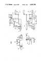
- FIG. 2is a basic circuit diagram of a control for the lathe presented in FIG. 1.
- a second cross slide K 2Opposite the main spindle and next to a tailstock 16 there is a second cross slide K 2 , including the usual longitudinal and transverse slides which are movable according to the coordinates X 2 and Z 2 .
- a turret indexing drive 18acts on the saddle W 2 which belongs to the cross slide K 2 .
- the drives in respect of the Z and X axesare marked by reference numerals 20 and 22.
- the tail spindle G sis controllable as to its rotary speed, its position along the Z axis is adjustable, and it can also be controlled in angular synchronism with the coordinated saddle W 3 (in the double spindle mode).
- FIG. 2is a diagrammatic presentation of the two control systems S 1 and S 2 for control of the turning machine shown in FIG. 1.
- the first control system S 1comprises X-axis and Z-axis controls as well as a so-called C-axis control including positional adjustment.
- the C-axis controlis left out.
- the controlled structural membersnamely the main spindle H s , the saddle W 1 (selectively with the tail spindle), W 2 and W 3 each comprise local circuits 40 controlled by switches 42 in both control systems S 1 and S 2 .
- the switches 42are coupled and movable into two positions. In the lower position II shown in FIG. 2 the lathe is controlled in the double slide mode, whereas it is controlled in the double spindle mode in position I shown in discontinuous lines.
- the values determined by the pick-ups 14, 29, 34are entered into the controls.
Landscapes
- Engineering & Computer Science (AREA)
- Mechanical Engineering (AREA)
- Automation & Control Theory (AREA)
- Manufacturing & Machinery (AREA)
- Physics & Mathematics (AREA)
- General Physics & Mathematics (AREA)
- Human Computer Interaction (AREA)
- Numerical Control (AREA)
- Turning (AREA)
- Electrical Discharge Machining, Electrochemical Machining, And Combined Machining (AREA)
- Liquid Crystal Substances (AREA)
- Exchange Systems With Centralized Control (AREA)
- Automatic Control Of Machine Tools (AREA)
Abstract
Description
TABLE I ______________________________________ (2 × 2) double slide (2 × 2) double spindle operating mode operating mode Mode System: Switchover S.sub.1 S.sub.2 S.sub.1 S.sub.2 ______________________________________ spindle main main tail spindle main spindle spindle spindle rotational X.sub.1 /Z.sub.1 X.sub.2 /Z.sub.2 X.sub.1 /Z.sub.1 X.sub.2 /Z.sub.2 feed thread main main tail spindle main spindle cutting spindle spindle velocity main main tail spindle main spindle constant spindle spindle C axis main -- tail spindle -- spindle driven W.sub.1 /W.sub.2 W.sub.1 /W.sub.2 W.sub.3 W.sub.2 very tools limited angular main -- tail spindle -- synchronization spindle -W.sub.1 -W.sub.3 ______________________________________
Claims (10)
Applications Claiming Priority (2)
| Application Number | Priority Date | Filing Date | Title |
|---|---|---|---|
| DE19853518792DE3518792A1 (en) | 1985-05-24 | 1985-05-24 | NUMERICALLY CONTROLLED LATHE |
| DE3518792 | 1985-05-24 |
Publications (1)
| Publication Number | Publication Date |
|---|---|
| US4683786Atrue US4683786A (en) | 1987-08-04 |
Family
ID=6271612
Family Applications (1)
| Application Number | Title | Priority Date | Filing Date |
|---|---|---|---|
| US06/851,455Expired - Fee RelatedUS4683786A (en) | 1985-05-24 | 1986-04-14 | Numerically controlled lathe |
Country Status (7)
| Country | Link |
|---|---|
| US (1) | US4683786A (en) |
| EP (1) | EP0203452B2 (en) |
| JP (1) | JPS61274801A (en) |
| AT (1) | ATE38631T1 (en) |
| BR (1) | BR8602329A (en) |
| DE (2) | DE3518792A1 (en) |
| ES (1) | ES8706497A1 (en) |
Cited By (15)
| Publication number | Priority date | Publication date | Assignee | Title |
|---|---|---|---|---|
| US4862380A (en)* | 1986-04-08 | 1989-08-29 | Fanuc Ltd | Numerical control unit |
| US4894596A (en)* | 1987-04-30 | 1990-01-16 | Fanuc Ltd. | Velocity control apparatus |
| US4970449A (en)* | 1987-11-20 | 1990-11-13 | Fanuc Ltd. | Numerical control apparatus |
| US5058029A (en)* | 1988-03-28 | 1991-10-15 | Yamazaki Mazak Kabushiki Kaisha | Setting control method of machining coordinate system in a machine tool |
| US5084660A (en)* | 1988-10-11 | 1992-01-28 | Fanuc, Ltd. | Nc command system |
| US5095598A (en)* | 1987-04-17 | 1992-03-17 | Yamazaki Mazak Corporation | Complex machining machine tool |
| US5097575A (en)* | 1987-04-17 | 1992-03-24 | Yamazaki Mazak Corporation | Complex machining machine tool |
| US5127140A (en)* | 1989-12-18 | 1992-07-07 | Hitachi Seiki Co., Ltd. | Numerically-controlled lathe, numerically-controlled device therefor and processing procedure thereby |
| US5175914A (en)* | 1987-04-28 | 1993-01-05 | Yamazaki Mazak Corporation | Machine tool having dual spindles and tool rests |
| US5181178A (en)* | 1989-02-22 | 1993-01-19 | Fanuc Ltd. | Spindle control command method |
| US5197363A (en)* | 1989-06-15 | 1993-03-30 | Mitsubishi Denki K.K. | Spindle driving device for a machine tool |
| US5207134A (en)* | 1991-01-21 | 1993-05-04 | Tsugami Corporation | Automatic precision lathe |
| US5676030A (en)* | 1995-08-14 | 1997-10-14 | Crudgington Machine Tools, Inc. | Multi-spindle CNC lathe |
| US6360637B1 (en)* | 2000-11-15 | 2002-03-26 | Weinraub Enterprises, Inc. | Tool for opening a locked vehicle door and method of making same |
| US6785943B2 (en) | 1998-09-04 | 2004-09-07 | Hardinge, Inc. | Indexing tool turret |
Families Citing this family (7)
| Publication number | Priority date | Publication date | Assignee | Title |
|---|---|---|---|---|
| GB8630495D0 (en)* | 1986-12-20 | 1987-01-28 | Wickman Bennett Machine Tool C | Lathes |
| US5319288A (en)* | 1989-10-06 | 1994-06-07 | Fanuc Ltd | Main spindle rotation control method |
| JPH03121748A (en)* | 1989-10-06 | 1991-05-23 | Fanuc Ltd | Spindle synchronous rotation control system |
| DE3933993C1 (en)* | 1989-10-11 | 1991-02-07 | Gildemeister Automation Gmbh, 3000 Hannover, De | |
| JP2692011B2 (en)* | 1990-02-09 | 1997-12-17 | 三菱電機株式会社 | Numerical control automatic programming device |
| DE19513963C2 (en)* | 1995-04-13 | 1998-05-28 | Gildemeister Ag | Numerically controlled lathe with a counter spindle |
| ITBO20070502A1 (en)* | 2007-07-20 | 2009-01-21 | Biesse Spa | AGGREGATE FOR ELECTROMANDRES |
Citations (11)
| Publication number | Priority date | Publication date | Assignee | Title |
|---|---|---|---|---|
| US3783719A (en)* | 1972-08-15 | 1974-01-08 | Warner Swasey Co | Machine tool |
| US3818301A (en)* | 1973-05-03 | 1974-06-18 | Warner Swasey Co | Multiplexed machine control apparatus |
| DE2702525A1 (en)* | 1976-01-23 | 1977-07-28 | Okuma Machinery Works Ltd | NUMERICAL CONTROL SYSTEM FOR A MACHINE TOOL |
| US4257103A (en)* | 1977-11-16 | 1981-03-17 | Heian Iron Works, Ltd. | Apparatus for controlling position of a plurality of machining shafts each including a machine tool fitted thereto |
| US4348623A (en)* | 1979-07-10 | 1982-09-07 | Fujitsu Fanuc Limited | Numerical control system for controlling both a machine tool and a robot |
| US4433383A (en)* | 1979-12-27 | 1984-02-21 | Roger Maurer | Installation comprising a plurality of numerically controlled machine tools |
| DE3320940A1 (en)* | 1983-06-09 | 1984-12-13 | G. Boley GmbH & Co, Werkzeugmaschinenfabrik, 7300 Esslingen | TWO-SPINDLE LATHE |
| US4497028A (en)* | 1980-09-30 | 1985-01-29 | Fanuc Ltd. | Numerical control system |
| US4514814A (en)* | 1982-09-07 | 1985-04-30 | General Electric Company | Multi-processor axis control |
| US4584638A (en)* | 1983-03-25 | 1986-04-22 | Mitsubishi Denki Kabushiki Kaisha | Numerical control apparatus |
| US4612832A (en)* | 1984-04-27 | 1986-09-23 | Kabushiki Kaisha Miyano Tekkosho | Multiple-function machine tool with two spindles |
Family Cites Families (1)
| Publication number | Priority date | Publication date | Assignee | Title |
|---|---|---|---|---|
| CH636543A5 (en)* | 1980-07-16 | 1983-06-15 | Tarex Sa | MACHINE TOOL COMPRISING TWO OPPOSITE COAXIAL SPINDLES. |
- 1985
- 1985-05-24DEDE19853518792patent/DE3518792A1/ennot_activeWithdrawn
- 1986
- 1986-04-04JPJP61078070Apatent/JPS61274801A/enactivePending
- 1986-04-14USUS06/851,455patent/US4683786A/ennot_activeExpired - Fee Related
- 1986-04-15ESES553973Apatent/ES8706497A1/ennot_activeExpired
- 1986-05-14EPEP86106528Apatent/EP0203452B2/ennot_activeExpired - Lifetime
- 1986-05-14ATAT86106528Tpatent/ATE38631T1/ennot_activeIP Right Cessation
- 1986-05-14DEDE8686106528Tpatent/DE3661171D1/ennot_activeExpired
- 1986-05-22BRBR8602329Apatent/BR8602329A/ennot_activeIP Right Cessation
Patent Citations (11)
| Publication number | Priority date | Publication date | Assignee | Title |
|---|---|---|---|---|
| US3783719A (en)* | 1972-08-15 | 1974-01-08 | Warner Swasey Co | Machine tool |
| US3818301A (en)* | 1973-05-03 | 1974-06-18 | Warner Swasey Co | Multiplexed machine control apparatus |
| DE2702525A1 (en)* | 1976-01-23 | 1977-07-28 | Okuma Machinery Works Ltd | NUMERICAL CONTROL SYSTEM FOR A MACHINE TOOL |
| US4257103A (en)* | 1977-11-16 | 1981-03-17 | Heian Iron Works, Ltd. | Apparatus for controlling position of a plurality of machining shafts each including a machine tool fitted thereto |
| US4348623A (en)* | 1979-07-10 | 1982-09-07 | Fujitsu Fanuc Limited | Numerical control system for controlling both a machine tool and a robot |
| US4433383A (en)* | 1979-12-27 | 1984-02-21 | Roger Maurer | Installation comprising a plurality of numerically controlled machine tools |
| US4497028A (en)* | 1980-09-30 | 1985-01-29 | Fanuc Ltd. | Numerical control system |
| US4514814A (en)* | 1982-09-07 | 1985-04-30 | General Electric Company | Multi-processor axis control |
| US4584638A (en)* | 1983-03-25 | 1986-04-22 | Mitsubishi Denki Kabushiki Kaisha | Numerical control apparatus |
| DE3320940A1 (en)* | 1983-06-09 | 1984-12-13 | G. Boley GmbH & Co, Werkzeugmaschinenfabrik, 7300 Esslingen | TWO-SPINDLE LATHE |
| US4612832A (en)* | 1984-04-27 | 1986-09-23 | Kabushiki Kaisha Miyano Tekkosho | Multiple-function machine tool with two spindles |
Cited By (17)
| Publication number | Priority date | Publication date | Assignee | Title |
|---|---|---|---|---|
| US4862380A (en)* | 1986-04-08 | 1989-08-29 | Fanuc Ltd | Numerical control unit |
| US5095598A (en)* | 1987-04-17 | 1992-03-17 | Yamazaki Mazak Corporation | Complex machining machine tool |
| US5097575A (en)* | 1987-04-17 | 1992-03-24 | Yamazaki Mazak Corporation | Complex machining machine tool |
| US5115546A (en)* | 1987-04-17 | 1992-05-26 | Yamazaki Mazak Corporation | Complex machining machine tool |
| US5175914A (en)* | 1987-04-28 | 1993-01-05 | Yamazaki Mazak Corporation | Machine tool having dual spindles and tool rests |
| US4894596A (en)* | 1987-04-30 | 1990-01-16 | Fanuc Ltd. | Velocity control apparatus |
| US4970449A (en)* | 1987-11-20 | 1990-11-13 | Fanuc Ltd. | Numerical control apparatus |
| US5058029A (en)* | 1988-03-28 | 1991-10-15 | Yamazaki Mazak Kabushiki Kaisha | Setting control method of machining coordinate system in a machine tool |
| US5084660A (en)* | 1988-10-11 | 1992-01-28 | Fanuc, Ltd. | Nc command system |
| US5181178A (en)* | 1989-02-22 | 1993-01-19 | Fanuc Ltd. | Spindle control command method |
| US5197363A (en)* | 1989-06-15 | 1993-03-30 | Mitsubishi Denki K.K. | Spindle driving device for a machine tool |
| US5127140A (en)* | 1989-12-18 | 1992-07-07 | Hitachi Seiki Co., Ltd. | Numerically-controlled lathe, numerically-controlled device therefor and processing procedure thereby |
| US5207134A (en)* | 1991-01-21 | 1993-05-04 | Tsugami Corporation | Automatic precision lathe |
| US5676030A (en)* | 1995-08-14 | 1997-10-14 | Crudgington Machine Tools, Inc. | Multi-spindle CNC lathe |
| US5918514A (en)* | 1995-08-14 | 1999-07-06 | Crudgington Machine Tools, Inc. | Multi-spindle CNC lathe |
| US6785943B2 (en) | 1998-09-04 | 2004-09-07 | Hardinge, Inc. | Indexing tool turret |
| US6360637B1 (en)* | 2000-11-15 | 2002-03-26 | Weinraub Enterprises, Inc. | Tool for opening a locked vehicle door and method of making same |
Also Published As
| Publication number | Publication date |
|---|---|
| EP0203452B2 (en) | 1993-09-29 |
| EP0203452A1 (en) | 1986-12-03 |
| ATE38631T1 (en) | 1988-12-15 |
| EP0203452B1 (en) | 1988-11-17 |
| JPS61274801A (en) | 1986-12-05 |
| DE3661171D1 (en) | 1988-12-22 |
| ES8706497A1 (en) | 1987-07-01 |
| DE3518792A1 (en) | 1986-11-27 |
| ES553973A0 (en) | 1987-07-01 |
| BR8602329A (en) | 1987-01-21 |
Similar Documents
| Publication | Publication Date | Title |
|---|---|---|
| US4683786A (en) | Numerically controlled lathe | |
| JP4619620B2 (en) | Automatic lathe | |
| USRE33732E (en) | Method of machining a workpiece in a turret lathe and an NC lathe for performing this method | |
| US4457193A (en) | Machine-tool comprising two opposed coaxial spindles | |
| EP0374259A4 (en) | Two opposed main shaft type cnc lathe | |
| US7043332B1 (en) | Numeric control lathe and method for controlling the same | |
| US5787560A (en) | Numerically controlled lathe | |
| GB2159450A (en) | Machine tool with two workpiece spindles | |
| EP0267288B1 (en) | Numerical control apparatus | |
| EP1383017B1 (en) | Automatic lathe, method for controlling the same, and device for controlling the same | |
| EP1383018B1 (en) | Automatic lathe, and method for controlling the same and device for controlling the same | |
| US5765456A (en) | Process for the machining of a workpiece on a CNC automatic lathe as well as a CNC automatic lathe | |
| JPS60232802A (en) | Machine tool | |
| JP2828232B2 (en) | Opposing spindle lathe | |
| JP2878690B2 (en) | Control method of numerically controlled lathe | |
| JP2807823B2 (en) | Work machining equipment for 2-spindle opposed CNC lathe | |
| JP2678838B2 (en) | Combined processing NC lathe | |
| GB2262061A (en) | Double spindle type lathe | |
| JPH03225505A (en) | Numerical controller with superposition control function | |
| JPH07185901A (en) | Superposition processing control method and numerical control apparatus thereof | |
| US5010492A (en) | Spindle control system and numerical control apparatus | |
| JPS6357101A (en) | Multispindle automatic lathe with numerical control device | |
| JPH0141449B2 (en) | ||
| CA2009993A1 (en) | Two-spindle opposed type cnc lathe | |
| JPS59175906A (en) | Numerical control lathe |
Legal Events
| Date | Code | Title | Description |
|---|---|---|---|
| AS | Assignment | Owner name:TRAUB AG, 7313 REICHENBACH/FILS ULMER STRASSE 49-5 Free format text:ASSIGNMENT OF ASSIGNORS INTEREST.;ASSIGNORS:KERSTEN, GUNTHER;KLAUSS, WALTER;MICHL, JURGEN;REEL/FRAME:004549/0938 Effective date:19860318 Owner name:TRAUB AG, GERMANY Free format text:ASSIGNMENT OF ASSIGNORS INTEREST;ASSIGNORS:KERSTEN, GUNTHER;KLAUSS, WALTER;MICHL, JURGEN;REEL/FRAME:004549/0938 Effective date:19860318 | |
| CC | Certificate of correction | ||
| FEPP | Fee payment procedure | Free format text:PAYOR NUMBER ASSIGNED (ORIGINAL EVENT CODE: ASPN); ENTITY STATUS OF PATENT OWNER: LARGE ENTITY | |
| FPAY | Fee payment | Year of fee payment:4 | |
| FPAY | Fee payment | Year of fee payment:8 | |
| AS | Assignment | Owner name:TRAUB DREHMASCHINEN GMBH, GERMANY Free format text:ASSIGNMENT OF ASSIGNORS INTEREST;ASSIGNOR:TRAUB AG;REEL/FRAME:009138/0189 Effective date:19980225 | |
| REMI | Maintenance fee reminder mailed | ||
| LAPS | Lapse for failure to pay maintenance fees | ||
| FP | Lapsed due to failure to pay maintenance fee | Effective date:19990804 | |
| STCH | Information on status: patent discontinuation | Free format text:PATENT EXPIRED DUE TO NONPAYMENT OF MAINTENANCE FEES UNDER 37 CFR 1.362 |