US4683528A - Pulse position modulated regulation for power supplies - Google Patents
Pulse position modulated regulation for power suppliesDownload PDFInfo
- Publication number
- US4683528A US4683528AUS06/757,808US75780885AUS4683528AUS 4683528 AUS4683528 AUS 4683528AUS 75780885 AUS75780885 AUS 75780885AUS 4683528 AUS4683528 AUS 4683528A
- Authority
- US
- United States
- Prior art keywords
- output
- coupled
- input
- pulse
- signal
- Prior art date
- Legal status (The legal status is an assumption and is not a legal conclusion. Google has not performed a legal analysis and makes no representation as to the accuracy of the status listed.)
- Expired - Lifetime
Links
Images

Classifications
- H—ELECTRICITY
- H02—GENERATION; CONVERSION OR DISTRIBUTION OF ELECTRIC POWER
- H02M—APPARATUS FOR CONVERSION BETWEEN AC AND AC, BETWEEN AC AND DC, OR BETWEEN DC AND DC, AND FOR USE WITH MAINS OR SIMILAR POWER SUPPLY SYSTEMS; CONVERSION OF DC OR AC INPUT POWER INTO SURGE OUTPUT POWER; CONTROL OR REGULATION THEREOF
- H02M3/00—Conversion of DC power input into DC power output
- H02M3/22—Conversion of DC power input into DC power output with intermediate conversion into AC
- H02M3/24—Conversion of DC power input into DC power output with intermediate conversion into AC by static converters
- H02M3/28—Conversion of DC power input into DC power output with intermediate conversion into AC by static converters using discharge tubes with control electrode or semiconductor devices with control electrode to produce the intermediate AC
- H02M3/325—Conversion of DC power input into DC power output with intermediate conversion into AC by static converters using discharge tubes with control electrode or semiconductor devices with control electrode to produce the intermediate AC using devices of a triode or a transistor type requiring continuous application of a control signal
- H02M3/335—Conversion of DC power input into DC power output with intermediate conversion into AC by static converters using discharge tubes with control electrode or semiconductor devices with control electrode to produce the intermediate AC using devices of a triode or a transistor type requiring continuous application of a control signal using semiconductor devices only
- H02M3/33507—Conversion of DC power input into DC power output with intermediate conversion into AC by static converters using discharge tubes with control electrode or semiconductor devices with control electrode to produce the intermediate AC using devices of a triode or a transistor type requiring continuous application of a control signal using semiconductor devices only with automatic control of the output voltage or current, e.g. flyback converters
- H02M3/33523—Conversion of DC power input into DC power output with intermediate conversion into AC by static converters using discharge tubes with control electrode or semiconductor devices with control electrode to produce the intermediate AC using devices of a triode or a transistor type requiring continuous application of a control signal using semiconductor devices only with automatic control of the output voltage or current, e.g. flyback converters with galvanic isolation between input and output of both the power stage and the feedback loop
- H—ELECTRICITY
- H02—GENERATION; CONVERSION OR DISTRIBUTION OF ELECTRIC POWER
- H02M—APPARATUS FOR CONVERSION BETWEEN AC AND AC, BETWEEN AC AND DC, OR BETWEEN DC AND DC, AND FOR USE WITH MAINS OR SIMILAR POWER SUPPLY SYSTEMS; CONVERSION OF DC OR AC INPUT POWER INTO SURGE OUTPUT POWER; CONTROL OR REGULATION THEREOF
- H02M1/00—Details of apparatus for conversion
- H02M1/0003—Details of control, feedback or regulation circuits
- H02M1/0006—Arrangements for supplying an adequate voltage to the control circuit of converters
Definitions
- the present inventionrelates to power supplies, and more particularly, to regulators for power supplies.
- One type of power supply circuitconverts the power which is available to power at the desired voltage (or current) level.
- the power input into the power supplyis often unregulated so that the voltage or current of the input power may vary.
- the load conditions on the power supplymay also vary. Both of these conditions can affect the output voltage (or current) of the power supply.
- a power supplyin which feedback information is transmitted in the form of a position modulated pulse.
- a pulseis generated at a time position which is a function of the deviation of the power supply output voltage.
- This pulsecan be transmitted across the isolation boundary between the primary and secondary coils by simple devices with little or no loss of fidelity.
- a pulse transformercan be used to transmit the pulse from the secondary coil side of the transformer to the primary coil side.
- the power through the primary coilis controlled by varying the duty cycle of the drive signal for a transistor switch.
- An additional advantage of the pulse position modulation approach of the present inventionis that the feedback pulse can be used to directly control the duty cycle of the switch drive signal. The above technique maintains the high linearity often necessary for accurate regulation while reducing the complexity of the regulator circuit.
- FIG. 1is a schematic diagram of a power supply system in accordance with a preferred embodiment of the present invention
- FIG. 2is a schematic diagram of the secondary controller circuit of the system of FIG. 1;
- FIG. 3is a schematic diagram of the primary controller circuit of the system of FIG. 1;
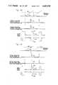
- FIG. 4Ais a timing diagram illustrating operation of the system of FIG. 1 for a normal output supply voltage
- FIG. 4Bis a timing diagram representing operation of the power supply system of FIG. 1 for a higher than normal output supply voltage.
- a power supply system in accordance with a preferred embodiment of the present inventionis indicated generally at 10.
- the system 10has a pair of input terminals 12 and 14 at which unregulated power is applied to the system.
- this unregulated poweris the form of direct current (DC) and is converted to highly regulated power provided at output terminals 16 and 18 of the system 10.
- DCdirect current
- the voltage of the output power at terminals 16 and 18is closely regulated to a predetermined value.
- Other applicationsmay require regulation of the power supply output current and it is recognized that the present invention is also applicable to such power supplies.
- the power supply system 10 of the illustrated embodimentis of the switched-mode type and includes a transformer 20 which has a primary coil 22 and a secondary coil 24.
- a transistor switch 26controls the flow of unregulated current through the primary coil 22 from the system input terminals 12 and 14.
- Current induced in the secondary coil 24flows through a diode 28 to a storage capacitor 30 coupled between the system output terminals 16 and 18.
- a secondary controller circuit 32monitors the supply voltage at the system output terminals 16 and 18 and generates a position modulated control pulse which is used to control the transistor switch 26 of the primary coil circuit.
- the position of the control pulse from the secondary controller 32represents the deviation of the supply voltage from a predetermined desired value.
- the conduction states of the transistor switch 26are controlled by a switch drive signal from an output 34 of a primary controller circuit 36.
- the primary controller circuit 36varies the duty cycle of the switch drive signal to the transistor switch 26 in accordance with the position of the position modulated control pulse from the secondary controller circuit 32.
- the output 38 of the secondary controller 32 for the position modulated control pulseis not connected directly to the input 40 of the primary controller 36. Instead, the output of the secondary controller circuit 32 is coupled by a pulse transformer 42 to the input of the primary controller circuit 36.
- the pulse transformer 42has an input coil 44 connected to the output 38 of the secondary controller 32 and an output coil 46 connected to the input 40 of the primary controller 36. It has been found that the pulse transformer 42 accurately transmits the position modulated control pulse across the isolation boundary of the transformer 20 while maintaining the isolation of the primary and secondary coils 22 and 24, respectively.
- the secondary controller circuit 32monitors the supply voltage across the output terminals 16 and 18 of the system 10, and generates a position modulated control pulse on the output 38.
- the position in time of this control pulsevaries with the deviation of the supply voltage from the desired value.
- FIG. 2An example of the secondary controller circuit 32 is shown in FIG. 2 to include a resistor divider comprising resistors 50 and 52 serially connected between the system output terminals 16 and 18 by a pair of conductors 53 and 55.
- a node 54 between the resistors 50 and 52provides a supply voltage sampling node for one input 56 of an error amplifier 58.
- the error amplifier 58compares a fraction of the system output supply voltage to a reference voltage provided by a voltage reference circuit 60, and provides an error signal at an output 62, which is proportional to the deviation of the fractional voltage at node 54 relative to the reference voltage.
- a sawtooth generator circuit 64converts the error signal from the amplifier 58 to a variable slope sawtooth waveform such as that illustrated at 66 in FIG. 4A.
- the slope of the waveforms generated by the generator 64vary inversely with the supply voltage of the system 10. Thus, for example, an increasing supply voltage decreases the slope of the sawtooth waveforms.
- the sawtooth waveform generator 64includes a variable current source 68 which has a control input coupled to the output 62 of the error amplifier 58.
- the current source 68charges a second storage capacitor 72 so that the voltage across the capacitor 72 at output 82 ramps upward at a rate determined by the current from the current source 68.
- a transistor switch 74 connected across the capacitor 72periodically shorts out the capacitor 72 to periodically reset the output 82 of the generator 64 as shown in FIG. 4A.
- the transistor switch 74is driven into conduction by a one shot circuit 76 which is periodically triggered by an input signal A from an input 78 of the secondary controller circuit 32.
- the input 78is coupled by a resistor 80 (FIG. 1) to the output of the secondary coil 24.
- the sawtooth waveform at the output 82 of the generator 64is compared by a comparator 84 to the reference voltage of the voltage reference circuit 60 of the secondary controller 32.
- the comparator circuit 84triggers a one shot circuit 88 which produces the position modulated control pulse 90 of FIG. 4A.
- the position (in time) at which the pulse is generateddepends upon the slope of the sawtooth waveform which as explained above, varies with changes in the supply voltage.
- control pulse 90is outputed on the output 38 of the secondary controller 32 to the input coil 44 of the pulse transformer 42, inducing a similar position modulated control pulse 92 (FIG. 4A) in the output coil 46 of the pulse transformer 42.
- the pulse transformer 42causes no significant alteration of the position in time of the position modulated control pulse.
- the position modulated control pulse from the secondary controller circuit 32controls the duty cycle of the switch drive signal from the primary controller 36 to the transistor switch 26 of the primary coil circuit.
- the primary controller circuit 36 of the illustrated embodimentincludes an RS-type flip-flop 100 which has a reset input R and a set input S.
- the Q output of the flip flop 100is coupled by a buffer circuit 102 to the output 34 to provide the switch drive signal of the primary controller 36.
- the position modulated control pulse from the secondary controller circuit 32(via the pulse transformer 42) is conditioned by a pulse conditioner circuit 104 and sets the flip-flop 100 of the primary controller circuit 36.
- the setting of the flip-flop 100produces a pulse 106 (FIG. 4A) in the switch drive signal thereby turning on the transistor switch 26 of the primary coil circuit.
- a negative pulse 108(FIG. 4A) in the output of the secondary coil 24 as represented by signal A.
- the transistor switch 26remains on until a pulse from a one-shot circuit 110 which is triggered by a clock pulse generator circuit 112, resets the flip-flop 100 of the primary controller circuit 36. This turns off the switch drive signal as indicated at 113 of the switch drive pulse 106 of FIG. 4A. Consequently, the secondary coil output pulse 108 is terminated as well as indicated at 115 in FIG. 4A.
- the clock pulses generated by the clock generator circuit 112are produced at a fixed frequency so that the transistor switch 26 of the primary coil circuit is always turned off at the same time in the illustrated embodiment.
- the frequency of the switching mode power supply system 10is set by the clock 112.
- the duty cycle of the switch drive signal and hence the turn on time of the transistor switch 26varies with the position of the position modulated control pulse from the secondary controller 32.
- the position (in time) of the position modulated control pulsedepends upon the slope of the sawtooth waveform which in turn depends upon the deviation of the predetermined fraction of the supply voltage from the reference voltage.
- FIG. 4Bshows a timing diagram illustrating the operation of the system 10 for the condition in which the output supply voltage is higher than that of the supply voltage for the circuit operation illustrated in FIG. 4A.
- the current produced by the current source 68 (FIG. 2) of the secondary controller 32is reduced so that the storage capacitor 72 charges at a slower rate. Therefore, the sawtooth waveform output of the generator 64 has a reduced slope so that it takes longer for the sawtooth waveform to reach the reference voltage.
- the position modulated control pulse 90'is produced later (displaced in time) as illustrated in FIG. 4B. Consequently, the switch drive signal of the primary controller 36 is turned on later reducing the duty cycle of the switch drive signal. As a result, the transistor switch 26 of the primary coil circuit is turned on for a shorter time causing a corresponding reduction in the supply voltage. The supply voltage will continue to decrease until it is restored to the level as set by the values of the resistors 50 and 52 and the reference voltage.
- the present inventionallows analog feedback information to be transmitted across the isolation boundary in a simple yet effective manner.
- a simple pulse transformercan be used to transmit the pulse with little or no loss of fidelity.
- the primary side of the transformeris controlled by varying the duty cycle signal of a switch drive signal, the feedback pulse can be used to directly determine the turn on point and no demodulation is necessary. This technique maintains the high linearity for accurate regulation and requires a relative minimum of circuitry.
Landscapes
- Engineering & Computer Science (AREA)
- Power Engineering (AREA)
- Dc-Dc Converters (AREA)
Abstract
Description
Claims (2)
Priority Applications (1)
| Application Number | Priority Date | Filing Date | Title |
|---|---|---|---|
| US06/757,808US4683528A (en) | 1985-07-22 | 1985-07-22 | Pulse position modulated regulation for power supplies |
Applications Claiming Priority (1)
| Application Number | Priority Date | Filing Date | Title |
|---|---|---|---|
| US06/757,808US4683528A (en) | 1985-07-22 | 1985-07-22 | Pulse position modulated regulation for power supplies |
Publications (1)
| Publication Number | Publication Date |
|---|---|
| US4683528Atrue US4683528A (en) | 1987-07-28 |
Family
ID=25049299
Family Applications (1)
| Application Number | Title | Priority Date | Filing Date |
|---|---|---|---|
| US06/757,808Expired - LifetimeUS4683528A (en) | 1985-07-22 | 1985-07-22 | Pulse position modulated regulation for power supplies |
Country Status (1)
| Country | Link |
|---|---|
| US (1) | US4683528A (en) |
Cited By (30)
| Publication number | Priority date | Publication date | Assignee | Title |
|---|---|---|---|---|
| US4809150A (en)* | 1988-01-27 | 1989-02-28 | Electric Power Research Institute, Inc. | DC to DC converter with feed forward and feed back regulation |
| EP0308622A1 (en)* | 1987-09-19 | 1989-03-29 | Deutsche Thomson-Brandt GmbH | Switching power supply |
| US4837495A (en)* | 1987-10-13 | 1989-06-06 | Astec U.S.A. (Hk) Limited | Current mode converter with controlled slope compensation |
| US4855885A (en)* | 1988-04-11 | 1989-08-08 | Dsl Dynamic Sciences Limited | Light beam intensifier |
| US4862339A (en)* | 1987-06-05 | 1989-08-29 | Yokogawa Electric Corporation | DC power supply with improved output stabilizing feedback |
| US4901215A (en)* | 1987-09-18 | 1990-02-13 | Seagate Technology, Inc. | Isolated switch mode power supply controller |
| US4930060A (en)* | 1988-03-10 | 1990-05-29 | Rca Licensing Corporation | Switch-mode power supply |
| US4937728A (en)* | 1989-03-07 | 1990-06-26 | Rca Licensing Corporation | Switch-mode power supply with burst mode standby operation |
| US4937468A (en)* | 1989-01-09 | 1990-06-26 | Sundstrand Corporation | Isolation circuit for pulse waveforms |
| US4967332A (en)* | 1990-02-26 | 1990-10-30 | General Electric Company | HVIC primary side power supply controller including full-bridge/half-bridge driver |
| US5034871A (en)* | 1989-03-28 | 1991-07-23 | Matsushita Electric Works, Ltd. | DC to DC converter with steady control of output DC voltage by monitoring output DC current |
| US5101336A (en)* | 1990-03-12 | 1992-03-31 | Alcatel N.V. | Switching converter |
| EP0332095A3 (en)* | 1988-03-10 | 1992-07-01 | RCA Thomson Licensing Corporation | A switch-mode power supply |
| US5448469A (en)* | 1990-02-15 | 1995-09-05 | Deutsche Thomson-Brandt Gmbh | Switch mode power supply with output feedback isolation |
| EP0740385A3 (en)* | 1995-04-29 | 1998-01-14 | THOMSON multimedia S.A. | Protection circuit for a switch mode power supply |
| US5757627A (en)* | 1996-05-01 | 1998-05-26 | Compaq Computer Corporation | Isolated power conversion with master controller in secondary |
| US6208531B1 (en)* | 1993-06-14 | 2001-03-27 | Vlt Corporation | Power converter having magnetically coupled control |
| US20040120163A1 (en)* | 2001-05-10 | 2004-06-24 | Fidelix Y.K. | Switching power supply apparatus |
| EP1257046A3 (en)* | 2001-05-10 | 2006-02-01 | Fidelix Y.K. | Switching power supply apparatus |
| US7123179B1 (en)* | 2003-02-21 | 2006-10-17 | National Semiconductor Corporation | Apparatus and method for duty cycle conversion |
| US7236086B1 (en) | 1993-06-14 | 2007-06-26 | Vlt, Inc. | Power converter configuration, control, and construction |
| US7558083B2 (en) | 1997-01-24 | 2009-07-07 | Synqor, Inc. | High efficiency power converter |
| US7564702B2 (en) | 1997-01-24 | 2009-07-21 | Synqor, Inc. | High efficiency power converter |
| US20110305043A1 (en)* | 2010-06-11 | 2011-12-15 | Murata Manufacturing Co., Ltd. | Isolated switching power supply apparatus |
| US20120081927A1 (en)* | 2010-04-08 | 2012-04-05 | Murata Manufacturing Co., Ltd. | Isolated switching power supply apparatus |
| US20130301310A1 (en)* | 2012-05-08 | 2013-11-14 | Chengdu Monolithic Power Systems Co., Ltd. | Isolated switching mode power supply and the method thereof |
| US9093910B1 (en)* | 2014-02-14 | 2015-07-28 | Maxim Integrated Products, Inc. | Predictive sampling for primary side sensing in isolated flyback converters |
| US9831782B2 (en)* | 2015-02-10 | 2017-11-28 | Infineon Technologies Austria Ag | Switched mode power supply with secondary-side power regulation |
| US10199950B1 (en) | 2013-07-02 | 2019-02-05 | Vlt, Inc. | Power distribution architecture with series-connected bus converter |
| CN113595396A (en)* | 2020-04-30 | 2021-11-02 | 万国半导体国际有限合伙公司 | Signal transmission circuit for supplying control information from secondary side to primary side of power converter and control circuit of power converter |
Citations (18)
| Publication number | Priority date | Publication date | Assignee | Title |
|---|---|---|---|---|
| US3879647A (en)* | 1974-06-07 | 1975-04-22 | Bell Telephone Labor Inc | DC to DC converter with regulation having accelerated soft start into active control region of regulation and fast response overcurrent limiting features |
| US3924172A (en)* | 1974-07-11 | 1975-12-02 | Honeywell Inf Systems | Power supply |
| US3935526A (en)* | 1972-08-14 | 1976-01-27 | Hitachi, Ltd. | DC-to-DC converter |
| US4063307A (en)* | 1976-06-28 | 1977-12-13 | Teletype Corporation | Direct current power converter with start-up and protection circuits |
| US4223378A (en)* | 1977-11-22 | 1980-09-16 | Sony Corporation | Switching regulator |
| US4276587A (en)* | 1976-01-23 | 1981-06-30 | Sony Corporation | DC to DC Converter |
| US4293902A (en)* | 1979-12-04 | 1981-10-06 | Ael Mirrotel, Ltd. | Transformerless fast current limiter with symetry correction for a switched-mode power supply |
| US4323961A (en)* | 1980-09-12 | 1982-04-06 | Astec Components, Ltd. | Free-running flyback DC power supply |
| US4347559A (en)* | 1981-03-02 | 1982-08-31 | Texas Instruments Incorporated | Switching power supply |
| US4357654A (en)* | 1979-12-19 | 1982-11-02 | Tsuneo Ikenoue | DC--DC Converter |
| US4389702A (en)* | 1980-08-20 | 1983-06-21 | International Rectifier Corporation | Switching power supply circuit having constant output for a wide range of input voltage |
| US4422139A (en)* | 1982-03-29 | 1983-12-20 | Rockwell International Corporation | Transformer coupled up-down converter |
| US4439821A (en)* | 1982-01-29 | 1984-03-27 | Varo, Inc. | DC to DC switching regulator with temperature compensated isolated feedback circuitry |
| US4453206A (en)* | 1981-12-14 | 1984-06-05 | Voight William C | Switching-mode power supply regulator |
| US4460951A (en)* | 1982-07-01 | 1984-07-17 | Honeywell Information Systems Inc. | Control circuit arrangement for a self-start power supply |
| US4561046A (en)* | 1983-12-22 | 1985-12-24 | Gte Automatic Electric Incorporated | Single transistor forward converter with lossless magnetic core reset and snubber network |
| US4562522A (en)* | 1983-12-30 | 1985-12-31 | Honeywell Inc. | Power supply for an electrostatic air cleaner with a modulated pulse width voltage input having a backup pulse width limiting means |
| US4608625A (en)* | 1983-04-27 | 1986-08-26 | Astec Components, Ltd. | Current driven flyback power supply |
- 1985
- 1985-07-22USUS06/757,808patent/US4683528A/ennot_activeExpired - Lifetime
Patent Citations (18)
| Publication number | Priority date | Publication date | Assignee | Title |
|---|---|---|---|---|
| US3935526A (en)* | 1972-08-14 | 1976-01-27 | Hitachi, Ltd. | DC-to-DC converter |
| US3879647A (en)* | 1974-06-07 | 1975-04-22 | Bell Telephone Labor Inc | DC to DC converter with regulation having accelerated soft start into active control region of regulation and fast response overcurrent limiting features |
| US3924172A (en)* | 1974-07-11 | 1975-12-02 | Honeywell Inf Systems | Power supply |
| US4276587A (en)* | 1976-01-23 | 1981-06-30 | Sony Corporation | DC to DC Converter |
| US4063307A (en)* | 1976-06-28 | 1977-12-13 | Teletype Corporation | Direct current power converter with start-up and protection circuits |
| US4223378A (en)* | 1977-11-22 | 1980-09-16 | Sony Corporation | Switching regulator |
| US4293902A (en)* | 1979-12-04 | 1981-10-06 | Ael Mirrotel, Ltd. | Transformerless fast current limiter with symetry correction for a switched-mode power supply |
| US4357654A (en)* | 1979-12-19 | 1982-11-02 | Tsuneo Ikenoue | DC--DC Converter |
| US4389702A (en)* | 1980-08-20 | 1983-06-21 | International Rectifier Corporation | Switching power supply circuit having constant output for a wide range of input voltage |
| US4323961A (en)* | 1980-09-12 | 1982-04-06 | Astec Components, Ltd. | Free-running flyback DC power supply |
| US4347559A (en)* | 1981-03-02 | 1982-08-31 | Texas Instruments Incorporated | Switching power supply |
| US4453206A (en)* | 1981-12-14 | 1984-06-05 | Voight William C | Switching-mode power supply regulator |
| US4439821A (en)* | 1982-01-29 | 1984-03-27 | Varo, Inc. | DC to DC switching regulator with temperature compensated isolated feedback circuitry |
| US4422139A (en)* | 1982-03-29 | 1983-12-20 | Rockwell International Corporation | Transformer coupled up-down converter |
| US4460951A (en)* | 1982-07-01 | 1984-07-17 | Honeywell Information Systems Inc. | Control circuit arrangement for a self-start power supply |
| US4608625A (en)* | 1983-04-27 | 1986-08-26 | Astec Components, Ltd. | Current driven flyback power supply |
| US4561046A (en)* | 1983-12-22 | 1985-12-24 | Gte Automatic Electric Incorporated | Single transistor forward converter with lossless magnetic core reset and snubber network |
| US4562522A (en)* | 1983-12-30 | 1985-12-31 | Honeywell Inc. | Power supply for an electrostatic air cleaner with a modulated pulse width voltage input having a backup pulse width limiting means |
Cited By (50)
| Publication number | Priority date | Publication date | Assignee | Title |
|---|---|---|---|---|
| US4862339A (en)* | 1987-06-05 | 1989-08-29 | Yokogawa Electric Corporation | DC power supply with improved output stabilizing feedback |
| US4901215A (en)* | 1987-09-18 | 1990-02-13 | Seagate Technology, Inc. | Isolated switch mode power supply controller |
| EP0308622A1 (en)* | 1987-09-19 | 1989-03-29 | Deutsche Thomson-Brandt GmbH | Switching power supply |
| US4837495A (en)* | 1987-10-13 | 1989-06-06 | Astec U.S.A. (Hk) Limited | Current mode converter with controlled slope compensation |
| US4809150A (en)* | 1988-01-27 | 1989-02-28 | Electric Power Research Institute, Inc. | DC to DC converter with feed forward and feed back regulation |
| WO1989007363A1 (en)* | 1988-01-27 | 1989-08-10 | Electric Power Research Institute, Inc. | Dc to dc converter with feed forward and feed back regulation |
| EP0332095A3 (en)* | 1988-03-10 | 1992-07-01 | RCA Thomson Licensing Corporation | A switch-mode power supply |
| US4930060A (en)* | 1988-03-10 | 1990-05-29 | Rca Licensing Corporation | Switch-mode power supply |
| US4855885A (en)* | 1988-04-11 | 1989-08-08 | Dsl Dynamic Sciences Limited | Light beam intensifier |
| US4937468A (en)* | 1989-01-09 | 1990-06-26 | Sundstrand Corporation | Isolation circuit for pulse waveforms |
| WO1990007825A1 (en)* | 1989-01-09 | 1990-07-12 | Sundstrand Corporation | Isolation circuit for pulse waveforms |
| US4937727A (en)* | 1989-03-07 | 1990-06-26 | Rca Licensing Corporation | Switch-mode power supply with transformer-coupled feedback |
| US4941078A (en)* | 1989-03-07 | 1990-07-10 | Rca Licensing Corporation | Synchronized switch-mode power supply |
| US4937728A (en)* | 1989-03-07 | 1990-06-26 | Rca Licensing Corporation | Switch-mode power supply with burst mode standby operation |
| US5034871A (en)* | 1989-03-28 | 1991-07-23 | Matsushita Electric Works, Ltd. | DC to DC converter with steady control of output DC voltage by monitoring output DC current |
| JP2686135B2 (en) | 1989-03-28 | 1997-12-08 | 松下電工株式会社 | Constant current power supply circuit |
| US5448469A (en)* | 1990-02-15 | 1995-09-05 | Deutsche Thomson-Brandt Gmbh | Switch mode power supply with output feedback isolation |
| US4967332A (en)* | 1990-02-26 | 1990-10-30 | General Electric Company | HVIC primary side power supply controller including full-bridge/half-bridge driver |
| US5101336A (en)* | 1990-03-12 | 1992-03-31 | Alcatel N.V. | Switching converter |
| US6208531B1 (en)* | 1993-06-14 | 2001-03-27 | Vlt Corporation | Power converter having magnetically coupled control |
| US7236086B1 (en) | 1993-06-14 | 2007-06-26 | Vlt, Inc. | Power converter configuration, control, and construction |
| EP0740385A3 (en)* | 1995-04-29 | 1998-01-14 | THOMSON multimedia S.A. | Protection circuit for a switch mode power supply |
| US5757627A (en)* | 1996-05-01 | 1998-05-26 | Compaq Computer Corporation | Isolated power conversion with master controller in secondary |
| US7564702B2 (en) | 1997-01-24 | 2009-07-21 | Synqor, Inc. | High efficiency power converter |
| US9143042B2 (en) | 1997-01-24 | 2015-09-22 | Synqor, Inc. | High efficiency power converter |
| US8493751B2 (en) | 1997-01-24 | 2013-07-23 | Synqor, Inc. | High efficiency power converter |
| US8023290B2 (en) | 1997-01-24 | 2011-09-20 | Synqor, Inc. | High efficiency power converter |
| US7558083B2 (en) | 1997-01-24 | 2009-07-07 | Synqor, Inc. | High efficiency power converter |
| US7023717B2 (en) | 2001-05-10 | 2006-04-04 | Fidelix Y.K. | Switching power supply apparatus |
| US20040120163A1 (en)* | 2001-05-10 | 2004-06-24 | Fidelix Y.K. | Switching power supply apparatus |
| EP1257046A3 (en)* | 2001-05-10 | 2006-02-01 | Fidelix Y.K. | Switching power supply apparatus |
| US7123179B1 (en)* | 2003-02-21 | 2006-10-17 | National Semiconductor Corporation | Apparatus and method for duty cycle conversion |
| US8374002B2 (en)* | 2010-04-08 | 2013-02-12 | Murata Manufacturing Co., Ltd. | Isolated switching power supply apparatus |
| US20120081927A1 (en)* | 2010-04-08 | 2012-04-05 | Murata Manufacturing Co., Ltd. | Isolated switching power supply apparatus |
| US20110305043A1 (en)* | 2010-06-11 | 2011-12-15 | Murata Manufacturing Co., Ltd. | Isolated switching power supply apparatus |
| JP2011259673A (en)* | 2010-06-11 | 2011-12-22 | Murata Mfg Co Ltd | Isolation type switching power supply |
| US8374003B2 (en)* | 2010-06-11 | 2013-02-12 | Murata Manufacturing Co., Ltd. | Isolated switching power supply apparatus |
| US20130301310A1 (en)* | 2012-05-08 | 2013-11-14 | Chengdu Monolithic Power Systems Co., Ltd. | Isolated switching mode power supply and the method thereof |
| US9595885B2 (en)* | 2012-05-08 | 2017-03-14 | Chengdu Monolithic Power Systems Co., Ltd. | Isolated switching mode power supply and the method thereof |
| US11705820B2 (en) | 2013-07-02 | 2023-07-18 | Vicor Corporation | Power distribution architecture with series-connected bus converter |
| US10199950B1 (en) | 2013-07-02 | 2019-02-05 | Vlt, Inc. | Power distribution architecture with series-connected bus converter |
| US10594223B1 (en) | 2013-07-02 | 2020-03-17 | Vlt, Inc. | Power distribution architecture with series-connected bus converter |
| US11075583B1 (en) | 2013-07-02 | 2021-07-27 | Vicor Corporation | Power distribution architecture with series-connected bus converter |
| US12395087B1 (en) | 2013-07-02 | 2025-08-19 | Vicor Corporation | Power distribution architecture with series-connected bus converter |
| US20150236602A1 (en)* | 2014-02-14 | 2015-08-20 | Maxim Integrated Products, Inc. | Predictive sampling for primary side sensing in isolated flyback converters |
| US9093910B1 (en)* | 2014-02-14 | 2015-07-28 | Maxim Integrated Products, Inc. | Predictive sampling for primary side sensing in isolated flyback converters |
| US9831782B2 (en)* | 2015-02-10 | 2017-11-28 | Infineon Technologies Austria Ag | Switched mode power supply with secondary-side power regulation |
| US11482936B2 (en)* | 2020-04-30 | 2022-10-25 | Alpha And Omega Semiconductor International Lp | Signal transmission circuit for providing control information from secondary side to primary side of power converter, and control circuit for power converter |
| CN113595396B (en)* | 2020-04-30 | 2024-06-11 | 万国半导体国际有限合伙公司 | Signal transmission circuit for providing control information from secondary side to primary side of power converter and control circuit of power converter |
| CN113595396A (en)* | 2020-04-30 | 2021-11-02 | 万国半导体国际有限合伙公司 | Signal transmission circuit for supplying control information from secondary side to primary side of power converter and control circuit of power converter |
Similar Documents
| Publication | Publication Date | Title |
|---|---|---|
| US4683528A (en) | Pulse position modulated regulation for power supplies | |
| US4825144A (en) | Dual channel current mode switching regulator | |
| US4030024A (en) | Switching power supply with floating internal supply circuit | |
| US4546421A (en) | Flyback feedforward pulse width modulation regulator | |
| US4717994A (en) | Current mode control for DC converters operating over 50% duty cycle | |
| US4302717A (en) | Power supply with increased dynamic range | |
| US5703764A (en) | Switched-mode power supply having standby operation | |
| US4032830A (en) | Modular constant current power supply | |
| US4174534A (en) | Master-slave voltage regulator employing pulse width modulation | |
| EP0059633B1 (en) | Switching power supply | |
| US4504898A (en) | Start-up transient control for a DC-to-DC converter powered by a current-limited source | |
| EP0255326A2 (en) | Current mode control arrangement with load dependent ramp signal added to sensed current waveform | |
| US5963438A (en) | Bi-directional magnetic isolator | |
| EP0228796A1 (en) | Start controlling circuit for adapting a constant current generator to a wide variety of loads | |
| CA1160284A (en) | Transformerless fast current limiter with symmetry correction for a switched-mode power supply | |
| US4386311A (en) | Dual slope pulse width modulation regulator and control system | |
| US5063489A (en) | Switching regulator having improved switching control arrangement | |
| EP0149312B1 (en) | Dc-dc converter | |
| US4439821A (en) | DC to DC switching regulator with temperature compensated isolated feedback circuitry | |
| US4694240A (en) | Switching regulator | |
| US5175675A (en) | Switching regulator in which oscillation is maintained below a predetermined frequency | |
| US4553198A (en) | Power converter symmetry correction circuit | |
| US5568226A (en) | Power supply device having control transistors connected in parallel with output voltage terminals | |
| US3898549A (en) | Variable duty cycle balanced DC/DC power converter | |
| US4460955A (en) | Stabilizing power supply apparatus |
Legal Events
| Date | Code | Title | Description |
|---|---|---|---|
| AS | Assignment | Owner name:INTERSIL, INC. 10600 RIDGEVIEW COURT, CUPERINO, CA Free format text:ASSIGNMENT OF ASSIGNORS INTEREST.;ASSIGNORS:SNOW, DANE R.;BINGHAM, DAVID;REEL/FRAME:004434/0355 Effective date:19850711 | |
| FEPP | Fee payment procedure | Free format text:PAYOR NUMBER ASSIGNED (ORIGINAL EVENT CODE: ASPN); ENTITY STATUS OF PATENT OWNER: LARGE ENTITY | |
| STCF | Information on status: patent grant | Free format text:PATENTED CASE | |
| FPAY | Fee payment | Year of fee payment:4 | |
| FEPP | Fee payment procedure | Free format text:PAYER NUMBER DE-ASSIGNED (ORIGINAL EVENT CODE: RMPN); ENTITY STATUS OF PATENT OWNER: LARGE ENTITY Free format text:PAYOR NUMBER ASSIGNED (ORIGINAL EVENT CODE: ASPN); ENTITY STATUS OF PATENT OWNER: LARGE ENTITY | |
| FPAY | Fee payment | Year of fee payment:8 | |
| FPAY | Fee payment | Year of fee payment:12 | |
| AS | Assignment | Owner name:INTERSIL CORPORATION, FLORIDA Free format text:ASSIGNMENT OF ASSIGNORS INTEREST;ASSIGNOR:HARRIS CORPORATION;REEL/FRAME:010263/0840 Effective date:19990813 | |
| AS | Assignment | Owner name:CREDIT SUISSE FIRST BOSTON, AS COLLATERAL AGENT, N Free format text:SECURITY INTEREST;ASSIGNOR:INTERSIL CORPORATION;REEL/FRAME:010351/0410 Effective date:19990813 |