US4683154A - Laser sealed vacuum insulation window - Google Patents
Laser sealed vacuum insulation windowDownload PDFInfo
- Publication number
- US4683154A US4683154AUS06/767,218US76721885AUS4683154AUS 4683154 AUS4683154 AUS 4683154AUS 76721885 AUS76721885 AUS 76721885AUS 4683154 AUS4683154 AUS 4683154A
- Authority
- US
- United States
- Prior art keywords
- glass
- panes
- edges
- panel
- resistant panel
- Prior art date
- Legal status (The legal status is an assumption and is not a legal conclusion. Google has not performed a legal analysis and makes no representation as to the accuracy of the status listed.)
- Expired - Fee Related
Links
- 238000009413insulationMethods0.000titledescription6
- 239000011521glassSubstances0.000claimsabstractdescription210
- 239000011324beadSubstances0.000claimsabstractdescription53
- 125000006850spacer groupChemical group0.000claimsabstractdescription16
- 238000003466weldingMethods0.000claimsabstractdescription15
- 238000000137annealingMethods0.000claimsabstractdescription7
- 238000000034methodMethods0.000claimsdescription29
- 230000005855radiationEffects0.000claimsdescription18
- 230000008569processEffects0.000claimsdescription15
- 229910052751metalInorganic materials0.000claimsdescription11
- 239000002184metalSubstances0.000claimsdescription11
- 238000010438heat treatmentMethods0.000claimsdescription8
- 238000002844meltingMethods0.000claimsdescription8
- 230000008018meltingEffects0.000claimsdescription8
- 238000007789sealingMethods0.000claimsdescription8
- 239000011248coating agentSubstances0.000claimsdescription7
- 238000000576coating methodMethods0.000claimsdescription7
- XEEYBQQBJWHFJM-UHFFFAOYSA-NIronChemical compound[Fe]XEEYBQQBJWHFJM-UHFFFAOYSA-N0.000claimsdescription6
- 238000001429visible spectrumMethods0.000claimsdescription6
- 229910003437indium oxideInorganic materials0.000claimsdescription5
- PJXISJQVUVHSOJ-UHFFFAOYSA-Nindium(iii) oxideChemical compound[O-2].[O-2].[O-2].[In+3].[In+3]PJXISJQVUVHSOJ-UHFFFAOYSA-N0.000claimsdescription5
- 239000000463materialSubstances0.000claimsdescription5
- 238000000151depositionMethods0.000claimsdescription3
- 229910001092metal group alloyInorganic materials0.000claimsdescription3
- 239000004065semiconductorSubstances0.000claimsdescription3
- QCWXUUIWCKQGHC-UHFFFAOYSA-NZirconiumChemical compound[Zr]QCWXUUIWCKQGHC-UHFFFAOYSA-N0.000claims1
- 229910052742ironInorganic materials0.000claims1
- 238000005476solderingMethods0.000claims1
- 229910052720vanadiumInorganic materials0.000claims1
- LEONUFNNVUYDNQ-UHFFFAOYSA-Nvanadium atomChemical compound[V]LEONUFNNVUYDNQ-UHFFFAOYSA-N0.000claims1
- 229910052726zirconiumInorganic materials0.000claims1
- 208000013201Stress fractureDiseases0.000abstract1
- 239000000758substrateSubstances0.000description19
- 238000012546transferMethods0.000description14
- 239000007789gasSubstances0.000description11
- 230000008901benefitEffects0.000description6
- 239000004115Sodium SilicateSubstances0.000description5
- NTHWMYGWWRZVTN-UHFFFAOYSA-Nsodium silicateChemical compound[Na+].[Na+].[O-][Si]([O-])=ONTHWMYGWWRZVTN-UHFFFAOYSA-N0.000description5
- 229910052911sodium silicateInorganic materials0.000description5
- 229910000679solderInorganic materials0.000description4
- 239000004033plasticSubstances0.000description3
- 229920003023plasticPolymers0.000description3
- 229920001296polysiloxanePolymers0.000description3
- IJGRMHOSHXDMSA-UHFFFAOYSA-NAtomic nitrogenChemical compoundN#NIJGRMHOSHXDMSA-UHFFFAOYSA-N0.000description2
- CURLTUGMZLYLDI-UHFFFAOYSA-NCarbon dioxideChemical compoundO=C=OCURLTUGMZLYLDI-UHFFFAOYSA-N0.000description2
- 229910000640Fe alloyInorganic materials0.000description2
- 229920006328StyrofoamPolymers0.000description2
- 229910000756V alloyInorganic materials0.000description2
- 229910001093Zr alloyInorganic materials0.000description2
- 239000005388borosilicate glassSubstances0.000description2
- 238000001816coolingMethods0.000description2
- 230000006872improvementEffects0.000description2
- 239000012212insulatorSubstances0.000description2
- 239000013521masticSubstances0.000description2
- 238000012986modificationMethods0.000description2
- 230000004048modificationEffects0.000description2
- 239000006060molten glassSubstances0.000description2
- 238000011160researchMethods0.000description2
- 239000008261styrofoamSubstances0.000description2
- 239000000126substanceSubstances0.000description2
- 238000013519translationMethods0.000description2
- GPPXJZIENCGNKB-UHFFFAOYSA-NvanadiumChemical compound[V]#[V]GPPXJZIENCGNKB-UHFFFAOYSA-N0.000description2
- JBRZTFJDHDCESZ-UHFFFAOYSA-NAsGaChemical compound[As]#[Ga]JBRZTFJDHDCESZ-UHFFFAOYSA-N0.000description1
- 229910001218Gallium arsenideInorganic materials0.000description1
- 238000013459approachMethods0.000description1
- QVGXLLKOCUKJST-UHFFFAOYSA-Natomic oxygenChemical compound[O]QVGXLLKOCUKJST-UHFFFAOYSA-N0.000description1
- 230000009286beneficial effectEffects0.000description1
- 238000004364calculation methodMethods0.000description1
- 229910002092carbon dioxideInorganic materials0.000description1
- 239000001569carbon dioxideSubstances0.000description1
- 230000015556catabolic processEffects0.000description1
- 150000001875compoundsChemical class0.000description1
- 238000004590computer programMethods0.000description1
- 238000010276constructionMethods0.000description1
- 230000003247decreasing effectEffects0.000description1
- 238000006731degradation reactionMethods0.000description1
- 229930195733hydrocarbonNatural products0.000description1
- 150000002430hydrocarbonsChemical class0.000description1
- 239000012774insulation materialSubstances0.000description1
- 238000004519manufacturing processMethods0.000description1
- 229910052757nitrogenInorganic materials0.000description1
- 239000001301oxygenSubstances0.000description1
- 229910052760oxygenInorganic materials0.000description1
- 230000002035prolonged effectEffects0.000description1
- 230000003014reinforcing effectEffects0.000description1
- 230000004044responseEffects0.000description1
- 230000000717retained effectEffects0.000description1
- 238000000926separation methodMethods0.000description1
- 238000004513sizingMethods0.000description1
- 239000007787solidSubstances0.000description1
- 238000001228spectrumMethods0.000description1
- 238000005507sprayingMethods0.000description1
- 238000004544sputter depositionMethods0.000description1
- 238000001771vacuum depositionMethods0.000description1
- XLYOFNOQVPJJNP-UHFFFAOYSA-NwaterChemical compoundOXLYOFNOQVPJJNP-UHFFFAOYSA-N0.000description1
Images


Classifications
- E—FIXED CONSTRUCTIONS
- E06—DOORS, WINDOWS, SHUTTERS, OR ROLLER BLINDS IN GENERAL; LADDERS
- E06B—FIXED OR MOVABLE CLOSURES FOR OPENINGS IN BUILDINGS, VEHICLES, FENCES OR LIKE ENCLOSURES IN GENERAL, e.g. DOORS, WINDOWS, BLINDS, GATES
- E06B3/00—Window sashes, door leaves, or like elements for closing wall or like openings; Layout of fixed or moving closures, e.g. windows in wall or like openings; Features of rigidly-mounted outer frames relating to the mounting of wing frames
- E06B3/66—Units comprising two or more parallel glass or like panes permanently secured together
- E06B3/6612—Evacuated glazing units
- C—CHEMISTRY; METALLURGY
- C03—GLASS; MINERAL OR SLAG WOOL
- C03B—MANUFACTURE, SHAPING, OR SUPPLEMENTARY PROCESSES
- C03B23/00—Re-forming shaped glass
- C03B23/20—Uniting glass pieces by fusing without substantial reshaping
- C03B23/24—Making hollow glass sheets or bricks
- C03B23/245—Hollow glass sheets
- E—FIXED CONSTRUCTIONS
- E06—DOORS, WINDOWS, SHUTTERS, OR ROLLER BLINDS IN GENERAL; LADDERS
- E06B—FIXED OR MOVABLE CLOSURES FOR OPENINGS IN BUILDINGS, VEHICLES, FENCES OR LIKE ENCLOSURES IN GENERAL, e.g. DOORS, WINDOWS, BLINDS, GATES
- E06B3/00—Window sashes, door leaves, or like elements for closing wall or like openings; Layout of fixed or moving closures, e.g. windows in wall or like openings; Features of rigidly-mounted outer frames relating to the mounting of wing frames
- E06B3/66—Units comprising two or more parallel glass or like panes permanently secured together
- E06B3/663—Elements for spacing panes
- E06B3/66304—Discrete spacing elements, e.g. for evacuated glazing units
- Y—GENERAL TAGGING OF NEW TECHNOLOGICAL DEVELOPMENTS; GENERAL TAGGING OF CROSS-SECTIONAL TECHNOLOGIES SPANNING OVER SEVERAL SECTIONS OF THE IPC; TECHNICAL SUBJECTS COVERED BY FORMER USPC CROSS-REFERENCE ART COLLECTIONS [XRACs] AND DIGESTS
- Y02—TECHNOLOGIES OR APPLICATIONS FOR MITIGATION OR ADAPTATION AGAINST CLIMATE CHANGE
- Y02A—TECHNOLOGIES FOR ADAPTATION TO CLIMATE CHANGE
- Y02A30/00—Adapting or protecting infrastructure or their operation
- Y02A30/24—Structural elements or technologies for improving thermal insulation
- Y02A30/249—Glazing, e.g. vacuum glazing
- Y—GENERAL TAGGING OF NEW TECHNOLOGICAL DEVELOPMENTS; GENERAL TAGGING OF CROSS-SECTIONAL TECHNOLOGIES SPANNING OVER SEVERAL SECTIONS OF THE IPC; TECHNICAL SUBJECTS COVERED BY FORMER USPC CROSS-REFERENCE ART COLLECTIONS [XRACs] AND DIGESTS
- Y02—TECHNOLOGIES OR APPLICATIONS FOR MITIGATION OR ADAPTATION AGAINST CLIMATE CHANGE
- Y02B—CLIMATE CHANGE MITIGATION TECHNOLOGIES RELATED TO BUILDINGS, e.g. HOUSING, HOUSE APPLIANCES OR RELATED END-USER APPLICATIONS
- Y02B80/00—Architectural or constructional elements improving the thermal performance of buildings
- Y02B80/22—Glazing, e.g. vaccum glazing
Definitions
- This inventionis generally related to thermal insulated windows and more specifically to a vacuum-sealed glass thermal pane window and a method of sealing same using laser energy.
- Panes of glassare in common use in situations wherein it is desired to allow visible light into a structure while preventing heat from escaping. Such situations include windows in buildings and solar collector panels.
- solar heating applicationsboth in active solar heating systems where solar collector panels are used to capture solar energy and in passive solar heated buildings where solar energy is admitted through large window areas, the heat gain over a period of time is a very important consideration that needs improvement.
- the heat gainis the difference between the heat energy collected in the structure from the sun's radiation less the heat lost from the structure.
- the ideal window or glass paneltherefore, would be one that is completely transparent to solar radiation and a perfect heat insulator. Such an ideal is, or course, unattainable, but improvements toward that ideal could significantly increase the efficiency of active and passive solar heating systems.
- thermal pane windowis shown in U.S. Pat. No. 4,295,305, issued to L. Shelver.
- Such thermal pane windowsas illustrated in the Shelver patent with two parallel, spaced apart panes of glass with an edge seal comprised of plastic, mastic, silicone, caulk, or the like, are generally effective to provide an R value of about 2.5 to 2.6. (R value is a standard unit indicative of resistance to heat transfer through a substance in terms of °F-ft 2 hr/BTU.)
- the air space between the panesinhibits direct conductance of the heat through the window; however, it does not inhibit heat loss by radiation. Further, it is known that the heat energy causes convection currents of air in the space between the panes. Such convection currents are very effective heat transfer vehicles for transferring heat from one pane to the other, thus negating much of the thermal resistance for which the air space between the glass panes is intended.
- tin-doped indium oxide (ITO) semiconductor material sputtered onto a glass substrateis selectively transparent to light in the solar spectrum but highly reflective to heat or infrared radiation from heated bodies.
- ITOindium oxide
- Such a tin-doped indium oxide layer deposited on a glass window panewill allow solar radiation, including solar infrared in the range of 2.2 microns wavelength, to pass through the glass into a building or into a solar collector panel while reflecting reradiated heat or infrared in the range of 7 to 10 microns.
- the captured heat energyis retained in the building or solar collector and not lost to the atmosphere.
- a general object of the present inventionis to provide a more thermal transfer resistant transparent panel for such uses as windows in passive solar heated buildings, solar panels, and the like.
- a more specific object of this inventionis to provide an evacuated thermal pane glass panel in which an extreme vacuum can be maintained for prolonged periods of time, such as 20 to 30 years or more.
- a further specific object of this inventionis to provide a method of sealing an evacuated space between adjacent panes of glass in a manner that will hold a vacuum approximately of 10 -6 Torr over a prolonged period of 20 to 30 years or more.
- the article and apparatus of this inventionmay comprise two adjacent glass panes spaced closely together with a plurality of spherical glass beads positioned between the panes to maintain the spacing therebetween and sealed with a glass seal around the edges.
- a selectively transparent coating on the interior surface of at least one of the glass panelsis provided to reflect heat infrared radiation while allowing solar radiation to pass through.
- the method of this inventionincludes depositing a selectively transparent layer on one of two glass panes, attaching a plurality of spherical glass bead spacers to the surface of one or two glass panes, positioning one of the glass panes on the other with the spacers between the two glass panes, positioning this assembly in a vacuum furnace, heating the assembly in a vacuum to the annealing temperature of the glass, and welding the edges of the glass panes together by directing a laser beam of sufficient energy thereon to heat the edges of the glass panes to the melting point.
- a reactive metal gettercan also be positioned in the evacuated space to eliminate trace gases accumulated therein.
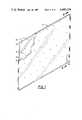
- FIG. 1is a perspective view of the evacuated thermal pane glass panel of the present invention with a portion of a corner broken away to reveal the structure thereof;
- FIG. 2is a cross-sectional view of the evacuated thermal pane glass panel of the present invention taken along lines 2--2 of FIG. 1;
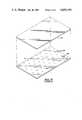
- FIG. 3is a cross-sectional view similar to FIG. 2, but with the addition of an insulating baffle around the edges of the glass panel;
- FIG. 4is a perspective view of one of the glass panes with a plurality of glass beads affixed thereto before to assembly with the second glass panel;
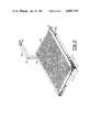
- FIG. 5is a perspective view illustrating a preferred method of affixing the glass beads to the glass pane
- FIG. 6is an enlarged elevation view illustrating the spot welding of a glass bead on the glass pane substrate
- FIG. 7is an enlarged elevation view illustrating an alternate method affixing the glass bead to the glass pane substrate with a sodium silicate solution
- FIG. 8is a cross-sectional view of a vacuum furnace arrangement suitably equipped for laser sealing of the edges of the evacuated thermal pane glass panel of the present invention.
- the laser-sealed vacuum insulating window 10 of the present inventionis best shown in FIG. 1, with secondary reference to FIG. 2.
- the window panel 10 according to the present inventionis comprised of two panes of glass 12, 14 positioned adjacent to each other in parallel, closely spaced-apart relation to each other. The edges are sealed together, as indicated at 16, to completely enclose and seal an evacuated space 30 between the glass panes 12, 14.
- a plurality of spherical glass bead spacersare positioned in spaced apart relation to each other throughout the evacuated space 30 between the glass panes 12, 14 to maintain the distance between the glass panes 12, 14, in spite of the intense vacuum sealed therein.
- a metal alloy getter 24is also positioned in the evacuated space 30 for purposes that will be described more fully below.
- the spherical glass spacers 20 positioned between the panels 12, 14maintain the distance and parallel relationship between the glass panels 12, 14.
- the extreme vacuumpreferably in the range of 10 -6 Torr would collapse or deform the glass panels 12, 14 into contact with each other, thereby short circuiting thermal transfer of energy directly therethrough by conduction and defeating the insulating purpose of the evacuated space.
- the glass beads 20are preferably spherical and approximately 0.5 mm in diameter.
- the size and spherical shape of such glass beads 20are significant in this application for several reasons.
- the spherical shapeprovides very small area, almost point, contacts between the beads 20 and the glass panes 12, 14.
- the smaller the sphere diameterthe smaller the contact area.
- a smaller contact arearesults in less area for heat conduction, thus more thermal resistance of the glass panel 10.
- smaller beads 20have less cross-sectional area and provide less of a conduction path through the bulk of the beads 20 themselves than larger beads. Therefore, thermal resistance of the glass panel 10 increases significantly as the size of the beads 20 is reduced, particularly in the range smaller than 1.0 mm diameter.
- a glass panel 10 with beads 20 in the range of about 0.5 mmprovides very good thermal resistance. It is possible to use even smaller beads 20 in the range of about 0.3 mm diameter, if the glass panels 12, 14 are very flat. For 0.5 mm diameter beads, spacing between beads 20 in the range of 2.5 to 3.5 cm is satisfactory to maintain the spacing between the glass panels 12, 14.
- glass beads 20 for use as spacers between the glass panes 12, 14are transparent like the glass. Thus, they are barely visible and do not detract from the appearance of the glass panel 10 or do not block a view therethrough when the glass is used as a window.
- the sealed vacuum insulating window panel 10which has a highly evacuated space 30 between the two glass panels 12, 14 and an all glass seal 16 around the edges of the individual panels 12, 14 is highly effective as a transparent insulating panel or window.
- Solar radiationcan pass freely therethrough into the interior of a building structure or solar collector panel, however, the heat absorbed inside the building or in a solar collector panel is very effectively prohibitied from transfer back through the glass panel 10.
- the selective coating 18, preferably of a layer of tin-doped indium oxide sputtered onto the surface of the glasseffectively reflects infrared heat radiation back into the building structure or solar panel. Further, the separation of the glass panels 12, 14 by the space 30 prevents conduction of heat from one side of the window 10 to the other.
- window panel 10that is exceptionally resistant to heat transfer therethrough.
- Theoretical calculations on window panels 10 constructed according to the present inventionhave indicated that they are expected to have an R value of approximately of 10 to 12, as opposed to conventional thermal pane windows that have an R value of only about 2.5.
- FIG. 3shows a preferred mounting structure for the evacuated glass panel 10 for the present invention.
- the edges 16 of the glass panel 10are preferably embedded in an insulated baffle 32 to minimize thermal conductance losses through the edge seal 16 of the glass panel 10.
- the edge seals 16are the only places where a significant cross-section of glass could provide a direct path for heat transfer by conduction from one side of the glass panel 10 to the other. Therefore, in order to prevent such a thermal short circuit, it is important to shield the end seal 16 from exposure to heat to prevent heat transfer therethrough. We have found that thermal resistance of a 1 m 2 glass panel is decreased by as much as 30% when the edge seals 16 are not shielded by the insulation baffle 32.
- Uniformly sized spherical glass beadsare inexpensive and readily available. They can be produced by persons skilled in the art, usually by spraying molten glass into a cool free-falling atmosphere. During the free fall, the droplets of molten glass solidify into almost perfect spheres.
- the spherical beadscan be screened for sizing to obtain uniform sizes for particular glass panel applications. It is preferred that the spherical glass beads used in this invention be approximately 0.5 mm in diameter.
- the glass beads 20can be affixed to the glass pane substrate 14 in a number of ways.
- One such method illustrated in FIG. 5is to "flood" or completely cover the entire surface of the glass pane substrate 14 with uniformly sized glass beads 20.
- a laser beam 46can be used to spot weld the individual glass beads 20 in the desired locations on the glass pane substrate 14.
- a convenient method of accomplishing this taskis to position the glass panel substrate 14 on a translation platform 48 that can be moved in predetermined precise X and Y directions under a stationary laser head. When the translation platform 48 is in the desired position, a laser beam 46 is produced by a laser head 40 and directed through a shroud 42 and relay mirror 44 to the surface of the glass pane substrate 14 as shown in FIG. 5.
- the laser beam 46is aimed at the glass substrate 14 in a vertical orientation, as shown in FIG. 6, then it does not matter whether the laser beam 46 is perfectly aligned with any particular glass sphere 20. As shown in FIG. 6, it is the nature of a spherical body 20 to refract a beam 46 to the contact point 47 between the spherical bead 20 and the glass substrate 14 where the spot welding takes place, regardless of which point on the surface of the spherical bead 20 the beam 46 is incident. Therefore, with the surface of the glass substrate 14 folded with beads 20, as shown in FIG. 5, any place the laser beam 46 is aimed at the substrate 14 in a vertical orientation thereto, a glass bead 20 will be spot welded to the glass substrate 14 at that selected location.
- the remainder of the glass beadscan merely be dumped or poured off the surface of the substrate 14, leaving a selected number of glass beads 20 affixed to the surface of the glass pane 14 at selected positions as shown in FIG. 4.
- Spot welding the beads 20 to the glass panel 14 in this mannerhas the advantage of keeping the contact area between the beads 20 and the glass pane 14.
- the spot weldsare also transparent, so they do not detract from the appearance of the window 10.
- FIG. 7illustrates another method of attaching the glass beads 20 to the substrate 14.
- the glass beads 20are dipped in a sodium silicate solution and positioned at the desired locations on the glass substrate 14.
- the sodium silicate solutionwill harden and adhere the glass bead 20 to the surface of the glass substrate 14.
- An advantage of this methodis that the sodium silicate does not produce any gases, is transparent, and provides a durable adhesion or bonding of the glass bead 20 to the glass substrate 14.
- a disadvantageis that the hardened sodium silicate 49 provides a larger surface area on at least one glass pane 14 to which it is affixed for thermal transfer by conduction.
- the other glass pane 12is positioned on the glass beads 20.
- the metal getter 24is positioned between the glass panels and, as best illustrated in FIG. 8, the assembly of glass panes 12, 14 and beads 20 is preferably positioned in a vacuum furnace 50 where the assembly can be heated to the annealing temperature of the glass while the edges 16 are sealed by a laser beam 76.
- a suitable vacuum furnace assembly 50is illustrated in cross-section in FIG. 8. It includes a vacuum chamber 54 enclosed by a vacuum shell 52. Reinforcing housing 53 provides additional structural support for the vacuum shell 52.
- a rotatable turntable platform 58is positioned in the chamber 54 to support the glass window panel 10 during laser welding.
- the turntable 58is supported by a rotatable shaft 62 journaled in a water-cooled bearing 63.
- a stepper motor 60 connected to the shaft 62rotates the turntable 58 in precisely measured increments of angular rotation in response to the stepper motor control apparatus (not shown).
- the glass panel assembly 10 on the turntableis heated by a plurality of radiant heating elements, such as the radiant heating element 56 in FIG. 8 positioned over the turntable 58.
- Primary reflective insulation layers 65protect the vacuum shell from the radiant heat in the chamber, and secondary reflective insulation layers 66 further shield structural and functional components of the furnace from the heat radiation.
- a view glass assembly 68 in removable end plate 67allows an operator to view the interior of the chamber 54.
- a laser optics housing unit 70is mounted above the turntable platform 58 and has a laser head 72 mounted thereon.
- a relay mirror 76is mounted on a pivotal axis 77 in laser optics housing 70 in alignment with a gallium arsenide laser window 74. The relay mirror 76 can direct laser beam 80 generated in the laser head 70 to a desired location on the turntable platform 58.
- the glass panel assembly 10comprised of the glass panes 12, 14, glass bead spaces 20, and metal getter 24 is positioned in the vaccuum furnace 50 on a thermofax board insulator 64 on the platform 58.
- the furnace 50is closed and sealed, and the chamber 54 is evacuated through port 55 to about 10 -6 Torr pressure.
- the radiant heaters 56heat the glass panel assembly 10 to its annealing temperature or slighly above.
- the annealing temperatureis approximately 565° C.; therefore, it is preferred that the glass assembly is heated to approximately 580° C., at which temperature the glass can deform slightly under stress without fracturing.
- the laser beam 81is directed at the edges of the glass panes 12, 14 to melt and weld them together to form a glass seal.
- the laser beam 76must have sufficient energy to raise the temperature of the glass at the edges enough to melt it.
- the melting temperature for borosilicate glassis approximately 1200° C. to 1300° C.
- any pattern or configuration of glass panel 10can have its edges laser welded to seal an evacuated space 30 therein as described above. This process can be watched through the view windows 68, 78.
- other vacuum furnace structures and laser control techniquescan also be used to accomplish the laser welding of the glass edges of panel 10.
- the glass panel assembly 10is welded in a vacuum tight glass seal as described above, it is cooled. While the glass panel 10 is cooling from the 580° C. oven temperature, it will give off minute amounts of water vapor, carbon dioxide, and other miscellaneous gases such as nitrogen, oxygen, hydrocarbons, and the like. These gases are emitted into the space 30 between the panes 12, 14, as well as to the exterior. However, the reactive metal getter 24, positioned between the glass panes 12, 14, is activated at the high oven temperature during the sealing process.
- This metal getter 24comprised preferably of an alloy of zirconium, vanadium and iron, will chemically react or combine with the minute amounts of gases produced during the cooling process to form solid compounds on the surface of the metal getter, thus virtually eliminating such gases from the space 30. With these gases eliminated, the 10 -6 Torr vacuum is maintained in the space 30 and the likelihood of heat loss caused by to convection currents therein is virtually eliminated.
- the amount of metal getter 24 to position in a particular evacuated glass panel 10 according to the present inventioncan be predetermined according to the size of the window panel 10 being produced.
- an evacuated window panel, 10 of approximately one square meterrequires a metal getter that is approximately 10 cm long by 0.08 cm wide by 0.35 cm thick, when the metal getter is an alloy of zirconium, vanadium and iron, as preferred in this invention.
- Other kinds of metal alloy getterscan also be used for the same purpose.
- a solder glassis a powdered glass having a low melting temperature that can be used to bond glasses with higher softening or melting points together.
- the powdered solder glasswould have to be placed between the edges of the adjacent glass panes 12, 14. Then, the laser directed at the edges would not have to raise the temperature of the glass panes 12, 14 to their melting points but would merely have to be of sufficient energy to melt the powdered glass solder at lower melting points.
Landscapes
- Engineering & Computer Science (AREA)
- Civil Engineering (AREA)
- Structural Engineering (AREA)
- Chemical & Material Sciences (AREA)
- Materials Engineering (AREA)
- Organic Chemistry (AREA)
- Joining Of Glass To Other Materials (AREA)
Abstract
Description
The U.S. Government has rights in this invention under Contract No. DE-AC02-83CH10093 between the U.S. Department of Energy and the Solar Energy Research Institute, a Division of Midwest Research Institute.
1. Field of the Invention
This invention is generally related to thermal insulated windows and more specifically to a vacuum-sealed glass thermal pane window and a method of sealing same using laser energy.
2. Description of the Prior Art
Panes of glass are in common use in situations wherein it is desired to allow visible light into a structure while preventing heat from escaping. Such situations include windows in buildings and solar collector panels. In solar heating applications, both in active solar heating systems where solar collector panels are used to capture solar energy and in passive solar heated buildings where solar energy is admitted through large window areas, the heat gain over a period of time is a very important consideration that needs improvement. The heat gain is the difference between the heat energy collected in the structure from the sun's radiation less the heat lost from the structure. The ideal window or glass panel, therefore, would be one that is completely transparent to solar radiation and a perfect heat insulator. Such an ideal is, or course, unattainable, but improvements toward that ideal could significantly increase the efficiency of active and passive solar heating systems.
It is well known and generally accepted that multiple, parallel, spaced-apart panes of glass provide more resistance to heat transfer than single panes of glass. An example of such a thermal pane window is shown in U.S. Pat. No. 4,295,305, issued to L. Shelver. Such thermal pane windows, as illustrated in the Shelver patent with two parallel, spaced apart panes of glass with an edge seal comprised of plastic, mastic, silicone, caulk, or the like, are generally effective to provide an R value of about 2.5 to 2.6. (R value is a standard unit indicative of resistance to heat transfer through a substance in terms of °F-ft2 hr/BTU.)
The air space between the panes inhibits direct conductance of the heat through the window; however, it does not inhibit heat loss by radiation. Further, it is known that the heat energy causes convection currents of air in the space between the panes. Such convection currents are very effective heat transfer vehicles for transferring heat from one pane to the other, thus negating much of the thermal resistance for which the air space between the glass panes is intended.
It is also known that evacuating the air and gases from the space between the glass panes minimizes or nearly eliminates the convection current therein. The U.S. Pat. No. 4,312,457, issued to R. Allaire, and the U.S. Pat. No. 4,393,105, issued to W. Kreisman, illustrate prior art attempts to provide evacuated window panes or structures to increase thermal resistance, i.e., to increase the R value.
Several problems are encountered in the prior art evacuated thermal pane windows. First, the vacuum between the glass panes causes the glass panes to bow or deflect toward each other. Such deflection can cause stress areas or even cracks in the glass. If they deflect enough to touch each other, short circuit heat transfer through direct conduction can occur, thus reducing thermal resistance significantly. The U.S. Pat. No. 3,990,201, issued to Falbel, shows the use of insulation spacers between panes of glass to solve this problem. However, such spacers are difficult to place in mass production, and they do transfer some heat because of their large contact surface areas with the glass panes, particularly when the spacing between the glass is small. Larger spacing between the panes of glass results in undesirable bulkiness. Further, one of the most signficant disadvantages of the Falbel approach is that such spacers are visible in transparent glass panels and are unsightly and distracting when used as windows in a building.
Another problem in prior art evacuated thermal pane windows is the difficulty of maintaining the vacuum over long periods of time. In general, the normal atmospheric pressure of about 1000 torr must be reduced to about 10-4 torr before any insulating benefits occur. To be beneficial in a practical insulating sense the pressure should be reduced even further to about 10-6 Torr. Sealing such a vacuum over an extended period of time is extremely difficult. Even effective short term seals that give off gases themselves or are even minutely gas permeable cannot maintain this kind of vacuum for very long. Therefore, known prior art seals of plastic, mastic, silicone, Styrofoam insulation, caulk, and the like are practically ineffective for this purpose. To be economical, the vacuum should be maintainable even up to 20-30 years or more. Plastics, silicone pastes, and caulks are permeable to air, and Styrofoam insulation materials give off gases themselves. Exposure to the sun speeds up this process.
Even the electrostatically bonded metal spacer frames taught by U.S. Pat. No. 4,393,105, issued to W. Kreisman, are not effective over longer periods of time. Such metal-to glass seals are subject to chemical attack and degradation, and are also susceptible to fatigue from stress cycles, deformation, and the like.
The prior art has, however, quite successfully solved the problem of reradiation of heat through the glass. For example, it is known that a coating of tin-doped indium oxide (ITO) semiconductor material sputtered onto a glass substrate is selectively transparent to light in the solar spectrum but highly reflective to heat or infrared radiation from heated bodies. Such a tin-doped indium oxide layer deposited on a glass window pane will allow solar radiation, including solar infrared in the range of 2.2 microns wavelength, to pass through the glass into a building or into a solar collector panel while reflecting reradiated heat or infrared in the range of 7 to 10 microns. Thus, the captured heat energy is retained in the building or solar collector and not lost to the atmosphere.
Accordingly, a general object of the present invention is to provide a more thermal transfer resistant transparent panel for such uses as windows in passive solar heated buildings, solar panels, and the like.
A more specific object of this invention is to provide an evacuated thermal pane glass panel in which an extreme vacuum can be maintained for prolonged periods of time, such as 20 to 30 years or more.
It is also a specific object of this invention to provide an evacuated thermal pane glass structure with effective transparent supports in the space between the glass panels that do not short circuit or transfer any significant amount of heat from one glass pane to the other.
A further specific object of this invention is to provide a method of sealing an evacuated space between adjacent panes of glass in a manner that will hold a vacuum approximately of 10-6 Torr over a prolonged period of 20 to 30 years or more.
Additional objects, advantages, and novel features of the invention are set forth in part in the description that follows, and in part will become apparent to those skilled in the art upon examination of the following specification or may be learned by the practice of the invention. The objects and advantages of the invention may be realized and attained by means of the instrumentalities, combinations, and method particularly pointed out in the appended claims.
To achieve the foregoing and other objects and in accordance with the purposes of the present invention, as embodied and broadly described herein, the article and apparatus of this invention may comprise two adjacent glass panes spaced closely together with a plurality of spherical glass beads positioned between the panes to maintain the spacing therebetween and sealed with a glass seal around the edges. A selectively transparent coating on the interior surface of at least one of the glass panels is provided to reflect heat infrared radiation while allowing solar radiation to pass through. Further, the method of this invention includes depositing a selectively transparent layer on one of two glass panes, attaching a plurality of spherical glass bead spacers to the surface of one or two glass panes, positioning one of the glass panes on the other with the spacers between the two glass panes, positioning this assembly in a vacuum furnace, heating the assembly in a vacuum to the annealing temperature of the glass, and welding the edges of the glass panes together by directing a laser beam of sufficient energy thereon to heat the edges of the glass panes to the melting point. A reactive metal getter can also be positioned in the evacuated space to eliminate trace gases accumulated therein.
The accompanying drawings, which are incorporated in and form a part of the specifications illustrate the preferred embodiments of the present invention, and together with the description explain the principles of the invention. In the drawings:
FIG. 1 is a perspective view of the evacuated thermal pane glass panel of the present invention with a portion of a corner broken away to reveal the structure thereof;
FIG. 2 is a cross-sectional view of the evacuated thermal pane glass panel of the present invention taken alonglines 2--2 of FIG. 1;
FIG. 3 is a cross-sectional view similar to FIG. 2, but with the addition of an insulating baffle around the edges of the glass panel;
FIG. 4 is a perspective view of one of the glass panes with a plurality of glass beads affixed thereto before to assembly with the second glass panel;
FIG. 5 is a perspective view illustrating a preferred method of affixing the glass beads to the glass pane;
FIG. 6 is an enlarged elevation view illustrating the spot welding of a glass bead on the glass pane substrate;
FIG. 7 is an enlarged elevation view illustrating an alternate method affixing the glass bead to the glass pane substrate with a sodium silicate solution; and
FIG. 8 is a cross-sectional view of a vacuum furnace arrangement suitably equipped for laser sealing of the edges of the evacuated thermal pane glass panel of the present invention.
The laser-sealedvacuum insulating window 10 of the present invention is best shown in FIG. 1, with secondary reference to FIG. 2. Thewindow panel 10 according to the present invention is comprised of two panes ofglass space 30 between theglass panes space 30 between theglass panes glass panes metal alloy getter 24 is also positioned in the evacuatedspace 30 for purposes that will be described more fully below.
Referring primarily now to FIG. 2, thespherical glass spacers 20 positioned between thepanels glass panels glass panels transparent coating 18, which is transparent to solar radiation and light in the visible spectrum but is reflective to infrared heat radiation, is deposited on the interior surface of one or both of theglass panels
Theglass beads 20 are preferably spherical and approximately 0.5 mm in diameter. The size and spherical shape ofsuch glass beads 20 are significant in this application for several reasons. The spherical shape provides very small area, almost point, contacts between thebeads 20 and theglass panes glass panel 10. Further,smaller beads 20 have less cross-sectional area and provide less of a conduction path through the bulk of thebeads 20 themselves than larger beads. Therefore, thermal resistance of theglass panel 10 increases significantly as the size of thebeads 20 is reduced, particularly in the range smaller than 1.0 mm diameter. We have found that aglass panel 10 withbeads 20 in the range of about 0.5 mm provides very good thermal resistance. It is possible to use evensmaller beads 20 in the range of about 0.3 mm diameter, if theglass panels beads 20 in the range of 2.5 to 3.5 cm is satisfactory to maintain the spacing between theglass panels
Another advantage of theglass beads 20 for use as spacers between theglass panes glass panel 10 or do not block a view therethrough when the glass is used as a window.
According to the present invention, the sealed vacuum insulatingwindow panel 10, which has a highly evacuatedspace 30 between the twoglass panels glass seal 16 around the edges of theindividual panels glass panel 10. Theselective coating 18, preferably of a layer of tin-doped indium oxide sputtered onto the surface of the glass, effectively reflects infrared heat radiation back into the building structure or solar panel. Further, the separation of theglass panels space 30 prevents conduction of heat from one side of thewindow 10 to the other. Still further, the extreme vacuum of approximately 10-6 Torr in thespace 30 between thepanes space 30 which would otherwise transfer heat from one pane to the other. The result is atransparent window panel 10 that is exceptionally resistant to heat transfer therethrough. Theoretical calculations onwindow panels 10 constructed according to the present invention have indicated that they are expected to have an R value of approximately of 10 to 12, as opposed to conventional thermal pane windows that have an R value of only about 2.5.
FIG. 3 shows a preferred mounting structure for the evacuatedglass panel 10 for the present invention. Theedges 16 of theglass panel 10 are preferably embedded in aninsulated baffle 32 to minimize thermal conductance losses through theedge seal 16 of theglass panel 10. The edge seals 16 are the only places where a significant cross-section of glass could provide a direct path for heat transfer by conduction from one side of theglass panel 10 to the other. Therefore, in order to prevent such a thermal short circuit, it is important to shield theend seal 16 from exposure to heat to prevent heat transfer therethrough. We have found that thermal resistance of a 1 m2 glass panel is decreased by as much as 30% when the edge seals 16 are not shielded by theinsulation baffle 32.
The sealed vacuum insulatingwindow panel 10 of the present invention is preferably constructed by using a laser to weld or seal the edges of theglass panels glass panes glass panels 14, as shown in FIG. 4.
Uniformly sized spherical glass beads are inexpensive and readily available. They can be produced by persons skilled in the art, usually by spraying molten glass into a cool free-falling atmosphere. During the free fall, the droplets of molten glass solidify into almost perfect spheres. The spherical beads can be screened for sizing to obtain uniform sizes for particular glass panel applications. It is preferred that the spherical glass beads used in this invention be approximately 0.5 mm in diameter.
Theglass beads 20 can be affixed to theglass pane substrate 14 in a number of ways. One such method illustrated in FIG. 5 is to "flood" or completely cover the entire surface of theglass pane substrate 14 with uniformlysized glass beads 20. Then, alaser beam 46 can be used to spot weld theindividual glass beads 20 in the desired locations on theglass pane substrate 14. A convenient method of accomplishing this task is to position theglass panel substrate 14 on atranslation platform 48 that can be moved in predetermined precise X and Y directions under a stationary laser head. When thetranslation platform 48 is in the desired position, alaser beam 46 is produced by alaser head 40 and directed through ashroud 42 andrelay mirror 44 to the surface of theglass pane substrate 14 as shown in FIG. 5.
If thelaser beam 46 is aimed at theglass substrate 14 in a vertical orientation, as shown in FIG. 6, then it does not matter whether thelaser beam 46 is perfectly aligned with anyparticular glass sphere 20. As shown in FIG. 6, it is the nature of aspherical body 20 to refract abeam 46 to thecontact point 47 between thespherical bead 20 and theglass substrate 14 where the spot welding takes place, regardless of which point on the surface of thespherical bead 20 thebeam 46 is incident. Therefore, with the surface of theglass substrate 14 folded withbeads 20, as shown in FIG. 5, any place thelaser beam 46 is aimed at thesubstrate 14 in a vertical orientation thereto, aglass bead 20 will be spot welded to theglass substrate 14 at that selected location. When thelaser beam 46 has been aimed at all of the selected locations where one desires to affix aglass bead 20 to theglass substrate 14, the remainder of the glass beads can merely be dumped or poured off the surface of thesubstrate 14, leaving a selected number ofglass beads 20 affixed to the surface of theglass pane 14 at selected positions as shown in FIG. 4. Spot welding thebeads 20 to theglass panel 14 in this manner has the advantage of keeping the contact area between thebeads 20 and theglass pane 14. The spot welds are also transparent, so they do not detract from the appearance of thewindow 10.
FIG. 7 illustrates another method of attaching theglass beads 20 to thesubstrate 14. In this method, theglass beads 20 are dipped in a sodium silicate solution and positioned at the desired locations on theglass substrate 14. The sodium silicate solution will harden and adhere theglass bead 20 to the surface of theglass substrate 14. An advantage of this method is that the sodium silicate does not produce any gases, is transparent, and provides a durable adhesion or bonding of theglass bead 20 to theglass substrate 14. A disadvantage is that thehardened sodium silicate 49 provides a larger surface area on at least oneglass pane 14 to which it is affixed for thermal transfer by conduction.
After theglass beads 20 are affixed at the desired locations to theglass pane 14, as shown in FIG. 4, theother glass pane 12 is positioned on theglass beads 20. Then, themetal getter 24 is positioned between the glass panels and, as best illustrated in FIG. 8, the assembly ofglass panes beads 20 is preferably positioned in a vacuum furnace 50 where the assembly can be heated to the annealing temperature of the glass while theedges 16 are sealed by alaser beam 76.
A suitable vacuum furnace assembly 50 is illustrated in cross-section in FIG. 8. It includes avacuum chamber 54 enclosed by avacuum shell 52. Reinforcinghousing 53 provides additional structural support for thevacuum shell 52. Arotatable turntable platform 58 is positioned in thechamber 54 to support theglass window panel 10 during laser welding. Theturntable 58 is supported by arotatable shaft 62 journaled in a water-cooledbearing 63. Astepper motor 60 connected to theshaft 62 rotates theturntable 58 in precisely measured increments of angular rotation in response to the stepper motor control apparatus (not shown).
Theglass panel assembly 10 on the turntable is heated by a plurality of radiant heating elements, such as theradiant heating element 56 in FIG. 8 positioned over theturntable 58. Primary reflective insulation layers 65 protect the vacuum shell from the radiant heat in the chamber, and secondary reflective insulation layers 66 further shield structural and functional components of the furnace from the heat radiation. Aview glass assembly 68 inremovable end plate 67 allows an operator to view the interior of thechamber 54.
A laseroptics housing unit 70 is mounted above theturntable platform 58 and has alaser head 72 mounted thereon. Arelay mirror 76 is mounted on apivotal axis 77 inlaser optics housing 70 in alignment with a galliumarsenide laser window 74. Therelay mirror 76 can directlaser beam 80 generated in thelaser head 70 to a desired location on theturntable platform 58.
In use, theglass panel assembly 10 comprised of theglass panes glass bead spaces 20, andmetal getter 24 is positioned in the vaccuum furnace 50 on athermofax board insulator 64 on theplatform 58. The furnace 50 is closed and sealed, and thechamber 54 is evacuated throughport 55 to about 10-6 Torr pressure. Then theradiant heaters 56 heat theglass panel assembly 10 to its annealing temperature or slighly above. For borosilicate glass, which is the preferred glass suggested for this invention, the annealing temperature is approximately 565° C.; therefore, it is preferred that the glass assembly is heated to approximately 580° C., at which temperature the glass can deform slightly under stress without fracturing. While maintaining the glass assembly at or slightly above the annealing temperature, the laser beam 81 is directed at the edges of theglass panes laser beam 76 must have sufficient energy to raise the temperature of the glass at the edges enough to melt it. The melting temperature for borosilicate glass is approximately 1200° C. to 1300° C. With thelaser beam 80 melting the glass at the edges of thepanes turntable platform 58 is rotated bystepper motor 60 in the appropriate increments. Simultaneously, therelay mirror 76 is rotated at appropriate increments and speeds to slowly move thelaser beam 76 around the entire edge of theglass panels relay mirror 76 and theturntable 58 simultaneously, preferably by computer program, any pattern or configuration ofglass panel 10 can have its edges laser welded to seal an evacuatedspace 30 therein as described above. This process can be watched through theview windows panel 10.
Once the entire edge of theglass panel assembly 10 is welded in a vacuum tight glass seal as described above, it is cooled. While theglass panel 10 is cooling from the 580° C. oven temperature, it will give off minute amounts of water vapor, carbon dioxide, and other miscellaneous gases such as nitrogen, oxygen, hydrocarbons, and the like. These gases are emitted into thespace 30 between thepanes reactive metal getter 24, positioned between theglass panes metal getter 24, comprised preferably of an alloy of zirconium, vanadium and iron, will chemically react or combine with the minute amounts of gases produced during the cooling process to form solid compounds on the surface of the metal getter, thus virtually eliminating such gases from thespace 30. With these gases eliminated, the 10-6 Torr vacuum is maintained in thespace 30 and the likelihood of heat loss caused by to convection currents therein is virtually eliminated.
The amount ofmetal getter 24 to position in a particular evacuatedglass panel 10 according to the present invention can be predetermined according to the size of thewindow panel 10 being produced. For example, an evacuated window panel, 10 of approximately one square meter requires a metal getter that is approximately 10 cm long by 0.08 cm wide by 0.35 cm thick, when the metal getter is an alloy of zirconium, vanadium and iron, as preferred in this invention. Other kinds of metal alloy getters can also be used for the same purpose.
While the above described laser welding edge seal is preferred, an alternative method of providing a glass edge seal is to use a glass solder technique. A solder glass is a powdered glass having a low melting temperature that can be used to bond glasses with higher softening or melting points together. In such an alternative embodiment, the powdered solder glass would have to be placed between the edges of theadjacent glass panes glass panes
The foregoing description illustrates only the principles of the invention. Further, since numerous modifications and changes will readily occur to those skilled in the art, it is not desired to limit the invention to the exact construction and processes shown and described above. Accordingly, all suitable modifications and equivalents may be resorted to falling within the scope of the invention as defined by the claims that follow.
Claims (19)
1. A thermal resistant panel comprising two panes of glass positioned closely spaced apart in substantially parallel relation to each other, a plurality of spherical glass bead spacers positioned between said two panes of glass to maintain the spacing while minimizing the thermal conduction between said panes, and a continuous glass joint around the periphery of said panel sealing the edges of said two panes together.
2. The thermal resistant panel of claim 1, wherein the space between said glass panes is evacuated.
3. The thermal resistant panel of claim 2, wherein the space between said glass panes is evacuated to a pressure in the range of 10-5 to 10-6 Torr.
4. The thermal resistant panel of claim 2, including getter means positioned in said evacuated space between said glass panes.
5. The thermal resistant panel of claim 3, wherein said getter means is an activated metal alloy comprising zirconium, vanadium, and iron.
6. The thermal resistant panel of claim 1, wherein said glass beads are in the range of about 0.3 mm to 1.0 mm in diameter.
7. The thermal resistant panel of claim 1, wherein said glass beads are affixed to one of said panels.
8. The thermal resistant panel of claim 1, including transparent selective coating means on the surface of one of said glass panes for allowing solar radiation and light in the visible spectrum to pass therethrough while reflecting infrared heat radiation that is not in the visible spectrum.
9. The thermal resistant panel of claim 1, wherein said panel includes an insulated baffle around the periphery of said panel enclosing said glass joint in said insulated baffle.
10. A thermal resistant panel conprising two panes of glass positioned closely spaced apart in relation to each other, at least one surface of one of said panes of glass having deposited thereon a layer of material that is transparent to solar radiation and light in the visible spectrum and reflective to infrared heat radiation that is not in the visible spectrum, a plurality of spherical glass bead spacers attached to one of said panes of glass and positioned in the space between said two panes of glass to maintain the spacing while minimizing the thermal conduction between said panes of glass, a continuous welded glass joint around the periphery of said panel sealing the edges of said two panes of glass together, and a vacuum in the space between said panes of glass.
11. A process of producing a thermal resistant panel comprising the steps of positioning two glass panes closely spaced apart in relation to each other, positioning a plurality of spherical glass bead spacers between said panes to maintain the spacing while minimizing the thermal conduction between said panes, evacuating the atmosphere around said panes, and joining the edges of said glass panes together to form a completely glass seal around the periphery of the panel.
12. The process of claim 11, including the step of glass soldering the edges of said glass panes together.
13. The process of claim 11, including the step of affixing a plurality of glass bead spacers to one of said glass panes by flooding the surface of said pane with a plurality of beads and then spot laser welding selected numbers thereof to said surface before welding the edges of said glass panes together.
14. The process of claim 12, including the step of affixing a plurality of glass bead spacers to one of said glass panes before welding the edges of said glass panes together.
15. The process of claim 12, including the step of welding the edges of said glass panes together by directing a laser beam at such edges of sufficient power to raise the temperature of the glass at the edges of the panes to the melting point.
16. The process of claim 15, including the step of heating said glass panes to at least the annealing temperature of the glass and maintaining such temperature during the laser welding of the edges together.
17. The process of claim 16, including the step of positioning metal getter means in the space between the glass panes prior to heating and welding the edges.
18. The process of claim 12, including the step of depositing a material on a surface of one of said glass panes that is transparent to solar radiation and visible light and reflective to infrared heat radiation that is not in the visible spectrum.
19. The process of claim 18, including the step of sputter depositing a layer of tin-doped indium oxide semiconductor material on a surface of one of said glass panes.
Priority Applications (1)
| Application Number | Priority Date | Filing Date | Title |
|---|---|---|---|
| US06/767,218US4683154A (en) | 1985-08-19 | 1985-08-19 | Laser sealed vacuum insulation window |
Applications Claiming Priority (1)
| Application Number | Priority Date | Filing Date | Title |
|---|---|---|---|
| US06/767,218US4683154A (en) | 1985-08-19 | 1985-08-19 | Laser sealed vacuum insulation window |
Publications (1)
| Publication Number | Publication Date |
|---|---|
| US4683154Atrue US4683154A (en) | 1987-07-28 |
Family
ID=25078844
Family Applications (1)
| Application Number | Title | Priority Date | Filing Date |
|---|---|---|---|
| US06/767,218Expired - Fee RelatedUS4683154A (en) | 1985-08-19 | 1985-08-19 | Laser sealed vacuum insulation window |
Country Status (1)
| Country | Link |
|---|---|
| US (1) | US4683154A (en) |
Cited By (150)
| Publication number | Priority date | Publication date | Assignee | Title |
|---|---|---|---|---|
| US4786344A (en)* | 1986-10-27 | 1988-11-22 | Owens-Corning Fiberglas Corporation | Evacuated dual pane window structure |
| WO1989009860A1 (en)* | 1988-04-15 | 1989-10-19 | Midwest Research Institute | Compact vacuum insulation |
| US4928448A (en)* | 1988-05-02 | 1990-05-29 | Enhanced Insulations, Inc. | Thermally insulating window and method of forming |
| US5005557A (en)* | 1985-11-29 | 1991-04-09 | Baechli Emil | Heat-insulating building and/or light element |
| US5021074A (en)* | 1988-01-22 | 1991-06-04 | Ppg Industries, Inc. | Method of and apparatus for joining edges of glass sheets, one of which has an electroconductive coating and the article made thereby |
| US5027574A (en)* | 1988-05-02 | 1991-07-02 | Phillip Bradley L | Thermally insulating structure |
| US5032439A (en)* | 1989-08-25 | 1991-07-16 | Massachusetts Institute Of Technology | Thermal insulations using vacuum panels |
| EP0421239A3 (en)* | 1989-10-03 | 1992-03-04 | Ppg Industries, Inc. | Vacuum insulation unit |
| US5106663A (en)* | 1989-03-07 | 1992-04-21 | Tremco Incorporated | Double-paned window system having controlled sealant thickness |
| US5107649A (en)* | 1988-04-15 | 1992-04-28 | Midwest Research Institute | Compact vacuum insulation embodiments |
| US5115612A (en)* | 1990-03-14 | 1992-05-26 | Vacuglas, Inc. | Transparent thermal panel |
| US5157893A (en)* | 1988-04-15 | 1992-10-27 | Midwest Research Institute | Compact vacuum insulation |
| US5175975A (en)* | 1988-04-15 | 1993-01-05 | Midwest Research Institute | Compact vacuum insulation |
| WO1993015296A1 (en)* | 1992-01-31 | 1993-08-05 | The University Of Sydney | Improvements to thermally insulating glass panels |
| EP0489042A4 (en)* | 1989-08-23 | 1993-11-18 | The University Of Sydney | A thermally insulating glass panel and method of construction |
| WO1994009333A1 (en)* | 1992-10-14 | 1994-04-28 | Midwest Research Institute | Dynamic vacuum insulation |
| US5477676A (en)* | 1988-04-15 | 1995-12-26 | Midwest Research Institute | Method and apparatus for thermal management of vehicle exhaust systems |
| US5489321A (en)* | 1994-07-14 | 1996-02-06 | Midwest Research Institute | Welding/sealing glass-enclosed space in a vacuum |
| US5643485A (en)* | 1988-04-15 | 1997-07-01 | Midwest Research Institute | Cooking utensil with improved heat retention |
| US5657607A (en)* | 1989-08-23 | 1997-08-19 | University Of Sydney | Thermally insulating glass panel and method of construction |
| US5705010A (en)* | 1992-03-19 | 1998-01-06 | Cardinal Ig Company | Multiple pane insulating glass unit with insulative spacer |
| WO1998004802A1 (en)* | 1996-07-31 | 1998-02-05 | Saint-Gobain Vitrage | Method for producing a vacuum between two glass sheets and insulating glazing |
| US5891536A (en)* | 1994-10-19 | 1999-04-06 | The University Of Sydney | Design improvements to vacuum glazing |
| US5902652A (en)* | 1993-06-30 | 1999-05-11 | University Of Sydney | Methods of construction of evacuated glazing |
| GB2336870A (en)* | 1998-05-01 | 1999-11-03 | David Livingstone | Evacuated double glazing arrangement incorporating spaced separators |
| WO2000028186A1 (en) | 1998-11-05 | 2000-05-18 | Luc Lafond | Apparatus and method for sealing insulated glass units |
| WO2000034614A1 (en)* | 1998-12-10 | 2000-06-15 | Saint-Gobain Glass France | Sealed vacuum double glazing and method for making same |
| US6103344A (en)* | 1997-01-09 | 2000-08-15 | Ngk Insulators, Ltd | Heat-fused unitary ferrule and method for producing the same |
| EP0978489A3 (en)* | 1998-08-07 | 2000-08-16 | Shinmaywa Industries, Ltd. | Glass fusing method and device |
| US6109994A (en)* | 1996-12-12 | 2000-08-29 | Candescent Technologies Corporation | Gap jumping to seal structure, typically using combination of vacuum and non-vacuum environments |
| US6139390A (en)* | 1996-12-12 | 2000-10-31 | Candescent Technologies Corporation | Local energy activation of getter typically in environment below room pressure |
| EP0999330A4 (en)* | 1998-05-07 | 2001-01-03 | Nippon Sheet Glass Co Ltd | Glass panel and method of manufacturing thereof and spacers used for glass panel |
| WO2001012941A1 (en) | 1999-08-18 | 2001-02-22 | Guardian Industries Corporation | Vacuum ig unit with spacer/pillar getter |
| US6194830B1 (en) | 1996-12-12 | 2001-02-27 | Candescent Technologies Corporation | Multi-compartment getter-containing flat-panel device |
| WO2001016045A1 (en)* | 1999-08-27 | 2001-03-08 | Qingdao Synergy Technology Appliance Co., Ltd. | The method for manufacturing vacuum glazing and its application mechanical system |
| US6216417B1 (en)* | 1997-07-07 | 2001-04-17 | Saint-Gobain Vitrage | Glazed element having a high insulating power provided with a plastic profile |
| RU2165510C1 (en)* | 2000-03-01 | 2001-04-20 | Ивлюшкин Алексей Николаевич | Glass block for windows |
| WO2001051752A1 (en) | 2000-01-11 | 2001-07-19 | Guardian Industries Corporation | Vacuum ig unit with colored spacers |
| US6291036B1 (en) | 1999-05-03 | 2001-09-18 | Guardian Industries Corporation | Vacuum IG window unit with spacers in seal |
| US6326067B1 (en) | 1999-05-03 | 2001-12-04 | Guardian Industries Corporation | Vacuum IG pillar with DLC coating |
| US6336984B1 (en) | 1999-09-24 | 2002-01-08 | Guardian Industries Corporation | Vacuum IG window unit with peripheral seal at least partially diffused at temper |
| WO2002014640A1 (en)* | 2000-08-11 | 2002-02-21 | Anthony John Cooper | Double glazing |
| US6352749B1 (en) | 1999-12-10 | 2002-03-05 | Guardian Industries Corp. | Vacuum IG unit with transparent spacers |
| US6365242B1 (en) | 1999-07-07 | 2002-04-02 | Guardian Industries Corp. | Peripheral seal for vacuum IG window unit |
| WO2002027135A1 (en)* | 2000-09-27 | 2002-04-04 | Guardian Industries Corp. | Edge seal for a vaccum insulating glazing unit |
| US6372312B1 (en) | 2000-02-17 | 2002-04-16 | Guardian Industries Corp. | Vacuum IG unit with micro-sized spacers |
| US20020050153A1 (en)* | 2000-03-01 | 2002-05-02 | Peter Schultz | Method and apparatus for creating a refractive gradient in glass using laser energy |
| DE10053402A1 (en)* | 2000-10-24 | 2002-05-02 | Inst Fuegetechnik Und Werkstof | Process and device for the thermal joining of components made of silicate materials, silicate composite materials and silicate composite materials |
| US6383580B1 (en) | 1999-11-12 | 2002-05-07 | Guardian Industries Corp. | Vacuum IG window unit with edge mounted pump-out tube |
| US6399169B1 (en) | 1999-07-07 | 2002-06-04 | Guardian Industries Corp. | Vacuum IG window unit with dual peripheral seal |
| US6436492B1 (en) | 1999-11-16 | 2002-08-20 | Guardian Industries Corp. | Vacuum IG window unit with fiber spacers |
| EP1010679A4 (en)* | 1998-05-19 | 2002-08-21 | Nippon Sheet Glass Co Ltd | GLASS PANEL |
| US6444281B1 (en) | 1999-10-13 | 2002-09-03 | Guardian Industries Corp. | Vacuum IG window unit with spacers between first and second edge seals |
| US6478911B1 (en) | 2000-09-27 | 2002-11-12 | Guardian Industries Corp. | Vacuum IG window unit with edge seal formed via microwave curing, and corresponding method of making the same |
| US6503583B2 (en) | 1999-11-16 | 2003-01-07 | Guardian Industries Corp. | Vacuum IG window unit with fiber inclusive edge seal |
| KR20030013032A (en)* | 2001-08-06 | 2003-02-14 | 주식회사 아이칸테크코리아 | Insulating and blinding system window consisted of pair glass using beads |
| US6541084B2 (en) | 2001-02-05 | 2003-04-01 | Guardian Industries Corp. | Vacuum IG window unit with polymer spacers |
| US6541083B1 (en) | 2000-01-11 | 2003-04-01 | Guardian Industries Corp. | Vacuum IG unit with alkali silicate edge seal and/or spacers |
| US6558494B1 (en) | 1999-09-24 | 2003-05-06 | Guardian Industries Corp. | Vacuum IG window unit with edge seal at least partially diffused at temper and completed via microwave curing, and corresponding method of making the same |
| US6637644B2 (en)* | 2001-01-09 | 2003-10-28 | Emil Bächli | Method of manufacturing heat insulating structural and/or light elements and installation for carrying out the method |
| US6722937B1 (en) | 2000-07-31 | 2004-04-20 | Candescent Technologies Corporation | Sealing of flat-panel device |
| US6830791B1 (en)* | 1998-09-14 | 2004-12-14 | Nippon Sheet Glass Co., Ltd. | Glass panel |
| US20070056626A1 (en)* | 2005-09-12 | 2007-03-15 | Solaria Corporation | Method and system for assembling a solar cell using a plurality of photovoltaic regions |
| US20070144085A1 (en)* | 2005-12-27 | 2007-06-28 | Jason Theios | High R-value window unit with vacuum IG unit and insulating frame |
| US20070245686A1 (en)* | 2006-03-31 | 2007-10-25 | Samuels Diane I | Method for manufacturing a filled insulated glass unit and such a unit |
| WO2006133126A3 (en)* | 2005-06-06 | 2007-11-01 | Solaria Corp | Method and system for integrated solar cell using a plurality of photovoltaic regions |
| USD568238S1 (en) | 2005-11-18 | 2008-05-06 | Solaria Corporation | Rectangular solar cell package design |
| US20080178922A1 (en)* | 2005-07-26 | 2008-07-31 | Solaria Corporation | Method and system for manufacturing solar panels using an integrated solar cell using a plurality of photovoltaic regions |
| US7419377B1 (en) | 2007-08-20 | 2008-09-02 | Solaria Corporation | Electrical coupling device and method for solar cells |
| US20080236664A1 (en)* | 2007-04-02 | 2008-10-02 | Solaria Corporation | Method and system for assembling a solar cell package |
| US20080236651A1 (en)* | 2007-04-02 | 2008-10-02 | Solaria Corporation | Solar cell concentrator structure including a plurality of concentrator elements with a notch design and method having a predetermined efficiency |
| US20090056788A1 (en)* | 2007-09-05 | 2009-03-05 | Solaria Corporation | Notch structure for concentrating module and method of manufacture using photovoltaic strips |
| USD588534S1 (en) | 2007-07-26 | 2009-03-17 | Solaria Corporation | Shaped solar cell package |
| US20090074997A1 (en)* | 2007-09-14 | 2009-03-19 | Electronics Packaging Solutions, Inc. | Insulating glass unit having multi-height internal standoffs and visible decoration |
| US7517712B2 (en) | 2002-03-22 | 2009-04-14 | Electronics Packaging Solutions, Inc. | Wafer-level hermetic micro-device packages |
| USD591229S1 (en) | 2008-01-24 | 2009-04-28 | Solaria Corporation | Shaped solar cell package |
| EP1826800A3 (en)* | 1996-12-12 | 2009-05-13 | Canon Kabushiki Kaisha | Gap jumping to seal structure |
| US20090151854A1 (en)* | 2007-12-14 | 2009-06-18 | Guardian Industries Corp. | Localized heating of edge seals for a vacuum insulating glass unit, and/or unitized oven for accomplishing the same |
| US20090151770A1 (en)* | 2007-12-12 | 2009-06-18 | Solaria Corporation | Method and material for coupling solar concentrators and photovoltaic devices |
| US20090188563A1 (en)* | 2007-09-05 | 2009-07-30 | Solaria Corporation | Solar Cell Structure Including A Plurality of Concentrator Elements With A Notch Design and Predetermined Radii and Method |
| US20100034996A1 (en)* | 2008-08-09 | 2010-02-11 | Lawrence Mott | Asymmetrical flexible edge seal for vacuum insulating glass |
| RU2382164C1 (en)* | 2008-12-11 | 2010-02-20 | Российская Академия сельскохозяйственных наук Государственное научное учреждение Всероссийский научно-исследовательский институт электрификации сельского хозяйства (ГНУ ВИЭСХ РОССЕЛЬХОЗАКАДЕМИИ) | Solar facade with vacuumised insulated glasing unit |
| WO2010043409A1 (en) | 2008-10-17 | 2010-04-22 | Ammersee Solar Gmbh | Solar generator |
| US20100107525A1 (en)* | 2008-11-05 | 2010-05-06 | Grzybowski Richard R | Vacuum-Insulated Glass Windows With Glass-Bump Spacers |
| US20100178439A1 (en)* | 2009-01-15 | 2010-07-15 | Eversealed Windows, Inc. | Flexible edge seal for vacuum insulating glazing units |
| US20100175347A1 (en)* | 2009-01-15 | 2010-07-15 | Bettger Kenneth J | Filament-strung stand-off elements for maintaining pane separation in vacuum insulating glazing units |
| US20100252698A1 (en)* | 2007-03-16 | 2010-10-07 | Dye Scott A | Integrated multilayer insulation |
| US20100251653A1 (en)* | 2007-03-16 | 2010-10-07 | Ball Aerospace & Technologies Corp. | Integrated Multilayer Insulation |
| US20100275654A1 (en)* | 2009-05-01 | 2010-11-04 | Guardian Industries Corp. | Vacuum insulating glass unit including infrared meltable glass frit, and/or method of making the same |
| US7832177B2 (en) | 2002-03-22 | 2010-11-16 | Electronics Packaging Solutions, Inc. | Insulated glazing units |
| US20110017263A1 (en)* | 2007-09-05 | 2011-01-27 | Solaria Corporation | Method and device for fabricating a solar cell using an interface pattern for a packaged design |
| US7910035B2 (en) | 2007-12-12 | 2011-03-22 | Solaria Corporation | Method and system for manufacturing integrated molded concentrator photovoltaic device |
| US7910822B1 (en) | 2005-10-17 | 2011-03-22 | Solaria Corporation | Fabrication process for photovoltaic cell |
| WO2011048313A1 (en) | 2009-10-22 | 2011-04-28 | Saint-Gobain Glass France | Tempered glass spacer |
| US8119902B2 (en) | 2007-05-21 | 2012-02-21 | Solaria Corporation | Concentrating module and method of manufacture for photovoltaic strips |
| CN102503094A (en)* | 2011-10-28 | 2012-06-20 | 天津森宇玻璃制造有限公司 | Producing method of vacuum glass with edge sealed under normal pressure and opening sealed under low pressure in vacuum furnace |
| CN102503095A (en)* | 2011-10-28 | 2012-06-20 | 天津森宇玻璃制造有限公司 | Melt-sealing structure of vacuum glass exhaust holes in vacuum state |
| CN101215076B (en)* | 2008-01-07 | 2012-07-04 | 左树森 | Method for preparing vacuum glass |
| US8227688B1 (en) | 2005-10-17 | 2012-07-24 | Solaria Corporation | Method and resulting structure for assembling photovoltaic regions onto lead frame members for integration on concentrating elements for solar cells |
| DE102011004176A1 (en)* | 2011-02-15 | 2012-08-16 | Von Ardenne Anlagentechnik Gmbh | Method for vacuum-tight joining of glass panes for production of vacuum insulation glass for use in building, involves heating material passed through glass panes, and locating heated jet outlet of energy beam in vacuum space |
| US20120247063A1 (en)* | 2011-03-29 | 2012-10-04 | Richard Robert Grzybowski | Light-weight strengthened, low-emittance vacuum insulated glass (vig) windows |
| CN103011573A (en)* | 2012-12-20 | 2013-04-03 | 天津盛泰通达机电技术咨询有限公司 | Manufacturing method of functional vacuum glass |
| US20130129944A1 (en)* | 2005-12-27 | 2013-05-23 | Guardian Industries Corp. | High r-value window unit |
| US20130142972A1 (en)* | 2011-12-05 | 2013-06-06 | Rayotek Scientific, Inc. | Vacuum Insulated Glass Panel with Spacers Coated with Micro Particles and Method of Forming Same |
| US20130153551A1 (en)* | 2011-12-15 | 2013-06-20 | Guardian Industries Corp. | Lighting solution for apparatuses for vacuum insulating glass (vig) unit tip-off, and/or associated methods |
| WO2013090667A1 (en)* | 2011-12-15 | 2013-06-20 | Guardian Industries Corp. | Apparatuses for vacuum insulating glass (vig) unit tip-off, and/or associated methods |
| US8513095B1 (en) | 2007-09-04 | 2013-08-20 | Solaria Corporation | Method and system for separating photovoltaic strips |
| WO2013130663A1 (en)* | 2012-02-29 | 2013-09-06 | Corning Incorporated | Glass vacuum insulating panels and methods |
| CN103420591A (en)* | 2013-07-17 | 2013-12-04 | 戴长虹 | Vacuum flat glass welded with seal strips, seal grooves and mounting holes |
| USD699176S1 (en) | 2011-06-02 | 2014-02-11 | Solaria Corporation | Fastener for solar modules |
| US8707736B2 (en) | 2007-08-06 | 2014-04-29 | Solaria Corporation | Method and apparatus for manufacturing solar concentrators using glass process |
| US8733128B2 (en) | 2011-02-22 | 2014-05-27 | Guardian Industries Corp. | Materials and/or method of making vacuum insulating glass units including the same |
| US8802203B2 (en) | 2011-02-22 | 2014-08-12 | Guardian Industries Corp. | Vanadium-based frit materials, and/or methods of making the same |
| US8950162B2 (en) | 2010-06-02 | 2015-02-10 | Eversealed Windows, Inc. | Multi-pane glass unit having seal with adhesive and hermetic coating layer |
| US20150047624A1 (en)* | 2012-05-03 | 2015-02-19 | Electrolux Home Products Corporation N.V. | Arrangement of glass panels for a heat insulated oven door for a cooking oven |
| US9187947B2 (en) | 2011-12-05 | 2015-11-17 | Rayotek Scientific, Inc. | Method of forming a vacuum insulated glass panel spacer |
| US9290408B2 (en) | 2011-02-22 | 2016-03-22 | Guardian Industries Corp. | Vanadium-based frit materials, and/or methods of making the same |
| US9309146B2 (en) | 2011-02-22 | 2016-04-12 | Guardian Industries Corp. | Vanadium-based frit materials, binders, and/or solvents and methods of making the same |
| US9328512B2 (en) | 2011-05-05 | 2016-05-03 | Eversealed Windows, Inc. | Method and apparatus for an insulating glazing unit and compliant seal for an insulating glazing unit |
| US9346710B2 (en) | 2012-05-29 | 2016-05-24 | Corning Incorporated | Sheet glass product fabrication with growth-limited glass bump spacers |
| US9359252B1 (en) | 2015-07-24 | 2016-06-07 | Corning Incorporated | Methods for controlled laser-induced growth of glass bumps on glass articles |
| US9359247B2 (en) | 2011-02-22 | 2016-06-07 | Guardian Industries Corp. | Coefficient of thermal expansion filler for vanadium-based frit materials and/or methods of making and/or using the same |
| WO2016089961A1 (en)* | 2014-12-03 | 2016-06-09 | Peter Petit | Low-friction spacer system for vacuum insulated glass |
| US9458052B2 (en) | 2011-02-22 | 2016-10-04 | Guardian Industries Corp. | Coefficient of thermal expansion filler for vanadium-based frit materials and/or methods of making and/or using the same |
| US20160297706A1 (en)* | 2013-12-11 | 2016-10-13 | Hitachi Chemical Company, Ltd. | Heat-insulating member, low-melting glass composition, and sealing material paste |
| US9498072B2 (en) | 2014-02-11 | 2016-11-22 | Anthony, Inc. | Display case door assembly with tempered glass vacuum panel |
| US9593527B2 (en) | 2014-02-04 | 2017-03-14 | Guardian Industries Corp. | Vacuum insulating glass (VIG) unit with lead-free dual-frit edge seals and/or methods of making the same |
| CN106573835A (en)* | 2014-07-30 | 2017-04-19 | 旭硝子株式会社 | Production method of vacuum multilayer glass, and vacuum multilayer glass |
| US9687087B1 (en) | 2016-06-16 | 2017-06-27 | Anthony, Inc. | Display case door assembly with vacuum panel and lighting features |
| US9784027B2 (en) | 2013-12-31 | 2017-10-10 | Guardian Glass, LLC | Vacuum insulating glass (VIG) unit with metallic peripheral edge seal and/or methods of making the same |
| US9822580B2 (en) | 2011-02-22 | 2017-11-21 | Guardian Glass, LLC | Localized heating techniques incorporating tunable infrared element(s) for vacuum insulating glass units, and/or apparatuses for same |
| US20180038152A1 (en)* | 2015-03-11 | 2018-02-08 | Panasonic Intellectual Property Management Co., Ltd. | Manufacturing method for glass panel unit and manufacturing method for glass window |
| US9896880B2 (en)* | 2012-05-25 | 2018-02-20 | Agc Glass Europe | Glazing panel comprising glass sheets linked together via spacers and corresponding production method |
| US9944452B1 (en) | 2014-12-12 | 2018-04-17 | Ball Aerospace & Technologies Corp. | Multi-layer insulation |
| US9988302B2 (en) | 2014-02-04 | 2018-06-05 | Guardian Glass, LLC | Frits for use in vacuum insulating glass (VIG) units, and/or associated methods |
| WO2018100440A1 (en) | 2016-12-01 | 2018-06-07 | Mechem Lab Ltd. | Activationless getters and method of their installation into vacuum insulated glazing |
| US10012019B2 (en) | 2013-12-31 | 2018-07-03 | Guardian Glass, LLC | Vacuum insulating glass (VIG) unit with metallic peripheral edge seal and/or methods of making the same |
| US10145005B2 (en) | 2015-08-19 | 2018-12-04 | Guardian Glass, LLC | Techniques for low temperature direct graphene growth on glass |
| USD837411S1 (en)* | 2016-12-09 | 2019-01-01 | Panasonic Intellectual Property Management Co., Ltd. | Vacuum-insulated glass plate |
| USD837412S1 (en)* | 2017-01-20 | 2019-01-01 | Panasonic Intellectual Property Management Co., Ltd. | Vacuum-insulated glass plate |
| US10165870B2 (en) | 2014-02-11 | 2019-01-01 | Anthony, Inc. | Display case door assembly with vacuum panel |
| US10247997B2 (en) | 2016-08-16 | 2019-04-02 | Cardinal Cg Company | Switchable hydride smart window and the methods for producing the same |
| US10280680B2 (en) | 2013-12-31 | 2019-05-07 | Guardian Glass, LLC | Vacuum insulating glass (VIG) unit with pump-out port sealed using metal solder seal, and/or method of making the same |
| WO2019149635A1 (en)* | 2018-02-01 | 2019-08-08 | Arcon Flachglas-Veredelung Gmbh & Co. Kg | Method for producing a glass sheet for vacuum insulating glass |
| EP3489202A4 (en)* | 2016-07-21 | 2019-08-14 | Panasonic Intellectual Property Management Co., Ltd. | METHOD AND APPARATUS FOR MANUFACTURING A GLASS PANEL FOR A GLASS PANEL UNIT |
| US10913232B2 (en) | 2016-08-30 | 2021-02-09 | Quest Thermal Group LLC | Cellular load-responsive multilayer insulation |
| US20210247153A1 (en)* | 2018-02-12 | 2021-08-12 | Delta Electronics, Inc. | Vapor chamber with support structure and manufacturing method therefor |
| US11247939B2 (en) | 2015-07-24 | 2022-02-15 | Corning Incorporated | Glass bumps on glass articles and methods of laser-induced growth |
| US20220372766A1 (en)* | 2020-01-29 | 2022-11-24 | SFS Group Fastening Technology Ltd. | Thermal insulation pad |
| CN118832926A (en)* | 2017-02-06 | 2024-10-25 | 肖特股份有限公司 | Insulating glass laminate with non-uniform coating and multiple sealed gas molecular cavities |
Citations (7)
| Publication number | Priority date | Publication date | Assignee | Title |
|---|---|---|---|---|
| GB1138992A (en)* | 1965-07-24 | 1969-01-01 | ||
| US3960534A (en)* | 1974-04-29 | 1976-06-01 | Rca Corporation | Method of assembling a liquid crystal cell |
| US3990201A (en)* | 1974-09-03 | 1976-11-09 | Gerald Falbel | Evacuated dual glazing system |
| US4039718A (en)* | 1975-12-19 | 1977-08-02 | Ppg Industries, Inc. | Hollow glass filaments sealed at both ends their production and their use as matrix reinforcing materials |
| US4198254A (en)* | 1976-11-26 | 1980-04-15 | Bfg Glassgroup | Vitreous sheets with synthetic polymer spacer and process for making the same |
| US4204015A (en)* | 1978-04-03 | 1980-05-20 | Levine Robert A | Insulating window structure and method of forming the same |
| US4339482A (en)* | 1980-08-29 | 1982-07-13 | Lucitron, Inc. | Flat-panel display and method of manufacture |
- 1985
- 1985-08-19USUS06/767,218patent/US4683154A/ennot_activeExpired - Fee Related
Patent Citations (7)
| Publication number | Priority date | Publication date | Assignee | Title |
|---|---|---|---|---|
| GB1138992A (en)* | 1965-07-24 | 1969-01-01 | ||
| US3960534A (en)* | 1974-04-29 | 1976-06-01 | Rca Corporation | Method of assembling a liquid crystal cell |
| US3990201A (en)* | 1974-09-03 | 1976-11-09 | Gerald Falbel | Evacuated dual glazing system |
| US4039718A (en)* | 1975-12-19 | 1977-08-02 | Ppg Industries, Inc. | Hollow glass filaments sealed at both ends their production and their use as matrix reinforcing materials |
| US4198254A (en)* | 1976-11-26 | 1980-04-15 | Bfg Glassgroup | Vitreous sheets with synthetic polymer spacer and process for making the same |
| US4204015A (en)* | 1978-04-03 | 1980-05-20 | Levine Robert A | Insulating window structure and method of forming the same |
| US4339482A (en)* | 1980-08-29 | 1982-07-13 | Lucitron, Inc. | Flat-panel display and method of manufacture |
Cited By (245)
| Publication number | Priority date | Publication date | Assignee | Title |
|---|---|---|---|---|
| US5009218A (en)* | 1985-11-29 | 1991-04-23 | Baechli Emil | Heat-insulating building and/or light element |
| US5005557A (en)* | 1985-11-29 | 1991-04-09 | Baechli Emil | Heat-insulating building and/or light element |
| US4786344A (en)* | 1986-10-27 | 1988-11-22 | Owens-Corning Fiberglas Corporation | Evacuated dual pane window structure |
| US5021074A (en)* | 1988-01-22 | 1991-06-04 | Ppg Industries, Inc. | Method of and apparatus for joining edges of glass sheets, one of which has an electroconductive coating and the article made thereby |
| US5562154A (en)* | 1988-04-15 | 1996-10-08 | Benson; David K. | Material-controlled dynamic vacuum insulation |
| US5175975A (en)* | 1988-04-15 | 1993-01-05 | Midwest Research Institute | Compact vacuum insulation |
| AU645481B2 (en)* | 1988-04-15 | 1994-01-20 | David K. Benson | Compact vacuum insulation |
| WO1989009860A1 (en)* | 1988-04-15 | 1989-10-19 | Midwest Research Institute | Compact vacuum insulation |
| US5477676A (en)* | 1988-04-15 | 1995-12-26 | Midwest Research Institute | Method and apparatus for thermal management of vehicle exhaust systems |
| US5157893A (en)* | 1988-04-15 | 1992-10-27 | Midwest Research Institute | Compact vacuum insulation |
| US5107649A (en)* | 1988-04-15 | 1992-04-28 | Midwest Research Institute | Compact vacuum insulation embodiments |
| US5643485A (en)* | 1988-04-15 | 1997-07-01 | Midwest Research Institute | Cooking utensil with improved heat retention |
| US5318108A (en)* | 1988-04-15 | 1994-06-07 | Midwest Research Institute | Gas-controlled dynamic vacuum insulation with gas gate |
| US4928448A (en)* | 1988-05-02 | 1990-05-29 | Enhanced Insulations, Inc. | Thermally insulating window and method of forming |
| US5027574A (en)* | 1988-05-02 | 1991-07-02 | Phillip Bradley L | Thermally insulating structure |
| US5106663A (en)* | 1989-03-07 | 1992-04-21 | Tremco Incorporated | Double-paned window system having controlled sealant thickness |
| US5657607A (en)* | 1989-08-23 | 1997-08-19 | University Of Sydney | Thermally insulating glass panel and method of construction |
| EP0489042A4 (en)* | 1989-08-23 | 1993-11-18 | The University Of Sydney | A thermally insulating glass panel and method of construction |
| US5032439A (en)* | 1989-08-25 | 1991-07-16 | Massachusetts Institute Of Technology | Thermal insulations using vacuum panels |
| US5124185A (en)* | 1989-10-03 | 1992-06-23 | Ppg Industries, Inc. | Vacuum insulating unit |
| EP0421239A3 (en)* | 1989-10-03 | 1992-03-04 | Ppg Industries, Inc. | Vacuum insulation unit |
| US5115612A (en)* | 1990-03-14 | 1992-05-26 | Vacuglas, Inc. | Transparent thermal panel |
| WO1993015296A1 (en)* | 1992-01-31 | 1993-08-05 | The University Of Sydney | Improvements to thermally insulating glass panels |
| US5664395A (en)* | 1992-01-31 | 1997-09-09 | The University Of Sydney | Thermally insulating glass panels |
| US5705010A (en)* | 1992-03-19 | 1998-01-06 | Cardinal Ig Company | Multiple pane insulating glass unit with insulative spacer |
| WO1994009333A1 (en)* | 1992-10-14 | 1994-04-28 | Midwest Research Institute | Dynamic vacuum insulation |
| US5902652A (en)* | 1993-06-30 | 1999-05-11 | University Of Sydney | Methods of construction of evacuated glazing |
| US6103324A (en)* | 1993-06-30 | 2000-08-15 | The University Of Sydney | Methods of construction of evacuated glazing |
| US5489321A (en)* | 1994-07-14 | 1996-02-06 | Midwest Research Institute | Welding/sealing glass-enclosed space in a vacuum |
| EP0771313A4 (en)* | 1994-07-14 | 1997-09-24 | Midwest Research Inst | Welding/sealing glass-enclosed space in a vacuum |
| US5891536A (en)* | 1994-10-19 | 1999-04-06 | The University Of Sydney | Design improvements to vacuum glazing |
| US6071575A (en)* | 1994-10-19 | 2000-06-06 | University Of Sydney | Vacuum glazing |
| US6054195A (en)* | 1994-10-19 | 2000-04-25 | University Of Sydney | Method of construction of evacuated glazing |
| US6083578A (en)* | 1994-10-19 | 2000-07-04 | University Of Sydney | Design improvements to vacuum glazing |
| US6261652B1 (en) | 1996-07-31 | 2001-07-17 | Saint-Gobain Vitrage | Method for producing a vacuum between two glass sheets and insulating glazing |
| US6488796B2 (en)* | 1996-07-31 | 2002-12-03 | Saint-Gobain Glass France | Method for producing a vacuum between two sheets of glass and insulating glazing |
| WO1998004802A1 (en)* | 1996-07-31 | 1998-02-05 | Saint-Gobain Vitrage | Method for producing a vacuum between two glass sheets and insulating glazing |
| EP1826800A3 (en)* | 1996-12-12 | 2009-05-13 | Canon Kabushiki Kaisha | Gap jumping to seal structure |
| US6416375B1 (en) | 1996-12-12 | 2002-07-09 | Candescent Technologies Corporation | Sealing of plate structures |
| US6109994A (en)* | 1996-12-12 | 2000-08-29 | Candescent Technologies Corporation | Gap jumping to seal structure, typically using combination of vacuum and non-vacuum environments |
| US6139390A (en)* | 1996-12-12 | 2000-10-31 | Candescent Technologies Corporation | Local energy activation of getter typically in environment below room pressure |
| US6194830B1 (en) | 1996-12-12 | 2001-02-27 | Candescent Technologies Corporation | Multi-compartment getter-containing flat-panel device |
| EP0944912B1 (en)* | 1996-12-12 | 2009-12-16 | Canon Kabushiki Kaisha | Gap jumping method of sealing plate structures |
| US6103344A (en)* | 1997-01-09 | 2000-08-15 | Ngk Insulators, Ltd | Heat-fused unitary ferrule and method for producing the same |
| US6216417B1 (en)* | 1997-07-07 | 2001-04-17 | Saint-Gobain Vitrage | Glazed element having a high insulating power provided with a plastic profile |
| GB2336870A (en)* | 1998-05-01 | 1999-11-03 | David Livingstone | Evacuated double glazing arrangement incorporating spaced separators |
| US6479112B1 (en) | 1998-05-07 | 2002-11-12 | Nippon Sheet Glass Co., Ltd. | Glass panel and method of manufacturing thereof and spacers used for glass panel |
| EP0999330A4 (en)* | 1998-05-07 | 2001-01-03 | Nippon Sheet Glass Co Ltd | Glass panel and method of manufacturing thereof and spacers used for glass panel |
| EP1428969A3 (en)* | 1998-05-07 | 2004-09-08 | Nippon Sheet Glass Co., Ltd. | Glass panel, its manufacturing method and spacer for use in the glass panel |
| EP1010679A4 (en)* | 1998-05-19 | 2002-08-21 | Nippon Sheet Glass Co Ltd | GLASS PANEL |
| EP0978489A3 (en)* | 1998-08-07 | 2000-08-16 | Shinmaywa Industries, Ltd. | Glass fusing method and device |
| US6830791B1 (en)* | 1998-09-14 | 2004-12-14 | Nippon Sheet Glass Co., Ltd. | Glass panel |
| US6332948B1 (en) | 1998-11-05 | 2001-12-25 | Luc Lafond | Apparatus and method for sealing insulated glass units |
| WO2000028186A1 (en) | 1998-11-05 | 2000-05-18 | Luc Lafond | Apparatus and method for sealing insulated glass units |
| WO2000034614A1 (en)* | 1998-12-10 | 2000-06-15 | Saint-Gobain Glass France | Sealed vacuum double glazing and method for making same |
| FR2787133A1 (en)* | 1998-12-10 | 2000-06-16 | Saint Gobain Vitrage | VACUUM INSULATING GLAZING AND METHOD FOR PRODUCING THE SAME |
| US6291036B1 (en) | 1999-05-03 | 2001-09-18 | Guardian Industries Corporation | Vacuum IG window unit with spacers in seal |
| US6326067B1 (en) | 1999-05-03 | 2001-12-04 | Guardian Industries Corporation | Vacuum IG pillar with DLC coating |
| US6399169B1 (en) | 1999-07-07 | 2002-06-04 | Guardian Industries Corp. | Vacuum IG window unit with dual peripheral seal |
| US6365242B1 (en) | 1999-07-07 | 2002-04-02 | Guardian Industries Corp. | Peripheral seal for vacuum IG window unit |
| US6420002B1 (en) | 1999-08-18 | 2002-07-16 | Guardian Industries Corp. | Vacuum IG unit with spacer/pillar getter |
| WO2001012941A1 (en) | 1999-08-18 | 2001-02-22 | Guardian Industries Corporation | Vacuum ig unit with spacer/pillar getter |
| WO2001016045A1 (en)* | 1999-08-27 | 2001-03-08 | Qingdao Synergy Technology Appliance Co., Ltd. | The method for manufacturing vacuum glazing and its application mechanical system |
| US6558494B1 (en) | 1999-09-24 | 2003-05-06 | Guardian Industries Corp. | Vacuum IG window unit with edge seal at least partially diffused at temper and completed via microwave curing, and corresponding method of making the same |
| US6641689B1 (en) | 1999-09-24 | 2003-11-04 | Guardian Industries Corp. | Vacuum IG window unit with peripheral seal at least partially diffused at temper |
| US6336984B1 (en) | 1999-09-24 | 2002-01-08 | Guardian Industries Corporation | Vacuum IG window unit with peripheral seal at least partially diffused at temper |
| US6444281B1 (en) | 1999-10-13 | 2002-09-03 | Guardian Industries Corp. | Vacuum IG window unit with spacers between first and second edge seals |
| US6383580B1 (en) | 1999-11-12 | 2002-05-07 | Guardian Industries Corp. | Vacuum IG window unit with edge mounted pump-out tube |
| US6436492B1 (en) | 1999-11-16 | 2002-08-20 | Guardian Industries Corp. | Vacuum IG window unit with fiber spacers |
| US6503583B2 (en) | 1999-11-16 | 2003-01-07 | Guardian Industries Corp. | Vacuum IG window unit with fiber inclusive edge seal |
| US6352749B1 (en) | 1999-12-10 | 2002-03-05 | Guardian Industries Corp. | Vacuum IG unit with transparent spacers |
| DE10085277B4 (en)* | 1999-12-10 | 2007-06-14 | Guardian Industries Corp., Auburn Hills | Thermally insulating glass unit |
| US6497931B1 (en) | 2000-01-11 | 2002-12-24 | Guardian Industries Corp. | Vacuum IG unit with colored spacers |
| WO2001051752A1 (en) | 2000-01-11 | 2001-07-19 | Guardian Industries Corporation | Vacuum ig unit with colored spacers |
| US6541083B1 (en) | 2000-01-11 | 2003-04-01 | Guardian Industries Corp. | Vacuum IG unit with alkali silicate edge seal and/or spacers |
| US6372312B1 (en) | 2000-02-17 | 2002-04-16 | Guardian Industries Corp. | Vacuum IG unit with micro-sized spacers |
| RU2165510C1 (en)* | 2000-03-01 | 2001-04-20 | Ивлюшкин Алексей Николаевич | Glass block for windows |
| US20020050153A1 (en)* | 2000-03-01 | 2002-05-02 | Peter Schultz | Method and apparatus for creating a refractive gradient in glass using laser energy |
| US6722937B1 (en) | 2000-07-31 | 2004-04-20 | Candescent Technologies Corporation | Sealing of flat-panel device |
| US7473152B1 (en) | 2000-07-31 | 2009-01-06 | Canon Kabushiki Kaisha | Sealing of flat-panel device |
| WO2002014640A1 (en)* | 2000-08-11 | 2002-02-21 | Anthony John Cooper | Double glazing |
| US6635321B2 (en) | 2000-09-27 | 2003-10-21 | Guardian Industries Corp. | Vacuum IG window unit with edge seal formed via microwave curing, and corresponding method of making the same |
| WO2002027135A1 (en)* | 2000-09-27 | 2002-04-04 | Guardian Industries Corp. | Edge seal for a vaccum insulating glazing unit |
| US6701749B2 (en) | 2000-09-27 | 2004-03-09 | Guardian Industries Corp. | Vacuum IG window unit with edge seal at least partially diffused at temper and completed via microwave curing, and corresponding method of making the same |
| US6478911B1 (en) | 2000-09-27 | 2002-11-12 | Guardian Industries Corp. | Vacuum IG window unit with edge seal formed via microwave curing, and corresponding method of making the same |
| EP1201610A3 (en)* | 2000-10-24 | 2004-01-14 | Institut für Fügetechnik und Werkstoffprüfung GmbH | Process and apparatus for thermally joining articles of silicate material |
| DE10053402A1 (en)* | 2000-10-24 | 2002-05-02 | Inst Fuegetechnik Und Werkstof | Process and device for the thermal joining of components made of silicate materials, silicate composite materials and silicate composite materials |
| DE10053402B4 (en)* | 2000-10-24 | 2008-04-17 | Institut für Fügetechnik und Werkstoffprüfung GmbH | Process and device for thermal joining of components made of silicate materials, silicate composites and silicate composite materials |
| US6637644B2 (en)* | 2001-01-09 | 2003-10-28 | Emil Bächli | Method of manufacturing heat insulating structural and/or light elements and installation for carrying out the method |
| US6541084B2 (en) | 2001-02-05 | 2003-04-01 | Guardian Industries Corp. | Vacuum IG window unit with polymer spacers |
| KR20030013032A (en)* | 2001-08-06 | 2003-02-14 | 주식회사 아이칸테크코리아 | Insulating and blinding system window consisted of pair glass using beads |
| US7517712B2 (en) | 2002-03-22 | 2009-04-14 | Electronics Packaging Solutions, Inc. | Wafer-level hermetic micro-device packages |
| US7832177B2 (en) | 2002-03-22 | 2010-11-16 | Electronics Packaging Solutions, Inc. | Insulated glazing units |
| WO2006133126A3 (en)* | 2005-06-06 | 2007-11-01 | Solaria Corp | Method and system for integrated solar cell using a plurality of photovoltaic regions |
| US20080178922A1 (en)* | 2005-07-26 | 2008-07-31 | Solaria Corporation | Method and system for manufacturing solar panels using an integrated solar cell using a plurality of photovoltaic regions |
| US20080236740A1 (en)* | 2005-07-26 | 2008-10-02 | Solaria Corporation | Method and system for manufacturing solar panels using an integrated solar cell using a plurality of photovoltaic regions |
| US20070056626A1 (en)* | 2005-09-12 | 2007-03-15 | Solaria Corporation | Method and system for assembling a solar cell using a plurality of photovoltaic regions |
| US20100282317A1 (en)* | 2005-09-12 | 2010-11-11 | Solaria Corporation | Method and system for assembling a solar cell using a plurality of photovoltaic regions |
| US20090120487A1 (en)* | 2005-09-12 | 2009-05-14 | Solaria Corporation | Method and System for Assembling A Solar Cell Using a Plurality of Photovoltaic Regions |
| US7910822B1 (en) | 2005-10-17 | 2011-03-22 | Solaria Corporation | Fabrication process for photovoltaic cell |
| US8227688B1 (en) | 2005-10-17 | 2012-07-24 | Solaria Corporation | Method and resulting structure for assembling photovoltaic regions onto lead frame members for integration on concentrating elements for solar cells |
| USD568238S1 (en) | 2005-11-18 | 2008-05-06 | Solaria Corporation | Rectangular solar cell package design |
| US7845142B2 (en)* | 2005-12-27 | 2010-12-07 | Guardian Industries Corp. | High R-value window unit with vacuum IG unit and insulating frame |
| US8900679B2 (en)* | 2005-12-27 | 2014-12-02 | Guardian Industries Corp. | High R-value window unit |
| US20070144085A1 (en)* | 2005-12-27 | 2007-06-28 | Jason Theios | High R-value window unit with vacuum IG unit and insulating frame |
| US20130129944A1 (en)* | 2005-12-27 | 2013-05-23 | Guardian Industries Corp. | High r-value window unit |
| US20070245686A1 (en)* | 2006-03-31 | 2007-10-25 | Samuels Diane I | Method for manufacturing a filled insulated glass unit and such a unit |
| US8266852B2 (en)* | 2006-03-31 | 2012-09-18 | Samuels Diane I | Method for manufacturing a filled insulated glass unit and such a unit |
| US20100251653A1 (en)* | 2007-03-16 | 2010-10-07 | Ball Aerospace & Technologies Corp. | Integrated Multilayer Insulation |
| US8234835B2 (en) | 2007-03-16 | 2012-08-07 | Quest Product Development Corporation | Integrated multilayer insulation |
| US7954301B2 (en) | 2007-03-16 | 2011-06-07 | Ball Aerospace & Technologies Corp. | Integrated multilayer insulation |
| US20100252698A1 (en)* | 2007-03-16 | 2010-10-07 | Dye Scott A | Integrated multilayer insulation |
| US20080236651A1 (en)* | 2007-04-02 | 2008-10-02 | Solaria Corporation | Solar cell concentrator structure including a plurality of concentrator elements with a notch design and method having a predetermined efficiency |
| US20080236664A1 (en)* | 2007-04-02 | 2008-10-02 | Solaria Corporation | Method and system for assembling a solar cell package |
| US7910392B2 (en) | 2007-04-02 | 2011-03-22 | Solaria Corporation | Method and system for assembling a solar cell package |
| US8119902B2 (en) | 2007-05-21 | 2012-02-21 | Solaria Corporation | Concentrating module and method of manufacture for photovoltaic strips |
| USD588534S1 (en) | 2007-07-26 | 2009-03-17 | Solaria Corporation | Shaped solar cell package |
| US8707736B2 (en) | 2007-08-06 | 2014-04-29 | Solaria Corporation | Method and apparatus for manufacturing solar concentrators using glass process |
| US7419377B1 (en) | 2007-08-20 | 2008-09-02 | Solaria Corporation | Electrical coupling device and method for solar cells |
| US8513095B1 (en) | 2007-09-04 | 2013-08-20 | Solaria Corporation | Method and system for separating photovoltaic strips |
| US8049098B2 (en) | 2007-09-05 | 2011-11-01 | Solaria Corporation | Notch structure for concentrating module and method of manufacture using photovoltaic strips |
| US20090188563A1 (en)* | 2007-09-05 | 2009-07-30 | Solaria Corporation | Solar Cell Structure Including A Plurality of Concentrator Elements With A Notch Design and Predetermined Radii and Method |
| US20110017263A1 (en)* | 2007-09-05 | 2011-01-27 | Solaria Corporation | Method and device for fabricating a solar cell using an interface pattern for a packaged design |
| US20090056788A1 (en)* | 2007-09-05 | 2009-03-05 | Solaria Corporation | Notch structure for concentrating module and method of manufacture using photovoltaic strips |
| US20090074997A1 (en)* | 2007-09-14 | 2009-03-19 | Electronics Packaging Solutions, Inc. | Insulating glass unit having multi-height internal standoffs and visible decoration |
| US7989040B2 (en) | 2007-09-14 | 2011-08-02 | Electronics Packaging Solutions, Inc. | Insulating glass unit having multi-height internal standoffs and visible decoration |
| US7910035B2 (en) | 2007-12-12 | 2011-03-22 | Solaria Corporation | Method and system for manufacturing integrated molded concentrator photovoltaic device |
| US20090151770A1 (en)* | 2007-12-12 | 2009-06-18 | Solaria Corporation | Method and material for coupling solar concentrators and photovoltaic devices |
| JP2011506252A (en)* | 2007-12-14 | 2011-03-03 | ガーディアン・インダストリーズ・コーポレーション | Local overheating of end seals for vacuum insulated glass units and / or unitized ovens to achieve them |
| US20090151854A1 (en)* | 2007-12-14 | 2009-06-18 | Guardian Industries Corp. | Localized heating of edge seals for a vacuum insulating glass unit, and/or unitized oven for accomplishing the same |
| US8500933B2 (en) | 2007-12-14 | 2013-08-06 | Guardian Industries Corp. | Localized heating of edge seals for a vacuum insulating glass unit, and/or unitized oven for accomplishing the same |
| US10703667B2 (en) | 2007-12-14 | 2020-07-07 | Guardian Glass, LLC | Localized heating of edge seals for a vacuum insulating glass unit, and/or unitized oven for accomplishing the same |
| RU2470129C2 (en)* | 2007-12-14 | 2012-12-20 | Гардиан Индастриз Корп. | Local heating of edge seals for vacuum insulation multiple glass pane and/or unified furnace for realisation of this glass pane |
| WO2009078912A1 (en)* | 2007-12-14 | 2009-06-25 | Guardian Industries Corp. | Localized heating of edge seals for a vacuum insulating glass unit, and/or unitized oven for accomplishing the same |
| CN101215076B (en)* | 2008-01-07 | 2012-07-04 | 左树森 | Method for preparing vacuum glass |
| USD591229S1 (en) | 2008-01-24 | 2009-04-28 | Solaria Corporation | Shaped solar cell package |
| US8283023B2 (en) | 2008-08-09 | 2012-10-09 | Eversealed Windows, Inc. | Asymmetrical flexible edge seal for vacuum insulating glass |
| US20100034996A1 (en)* | 2008-08-09 | 2010-02-11 | Lawrence Mott | Asymmetrical flexible edge seal for vacuum insulating glass |
| WO2010043409A1 (en) | 2008-10-17 | 2010-04-22 | Ammersee Solar Gmbh | Solar generator |
| US20100107525A1 (en)* | 2008-11-05 | 2010-05-06 | Grzybowski Richard R | Vacuum-Insulated Glass Windows With Glass-Bump Spacers |
| US20140202209A1 (en)* | 2008-11-05 | 2014-07-24 | Corning Incorporated | Vacuum-insulated glass windows with glass-bump spacers |
| US8821999B2 (en) | 2008-11-05 | 2014-09-02 | Corning Incorporated | Vacuum-insulated glass windows with glass-bump spacers |
| US8955358B2 (en)* | 2008-11-05 | 2015-02-17 | Corning Incorporated | Vacuum-insulated glass windows with glass-bump spacers |
| RU2382164C1 (en)* | 2008-12-11 | 2010-02-20 | Российская Академия сельскохозяйственных наук Государственное научное учреждение Всероссийский научно-исследовательский институт электрификации сельского хозяйства (ГНУ ВИЭСХ РОССЕЛЬХОЗАКАДЕМИИ) | Solar facade with vacuumised insulated glasing unit |
| US8512830B2 (en) | 2009-01-15 | 2013-08-20 | Eversealed Windows, Inc. | Filament-strung stand-off elements for maintaining pane separation in vacuum insulating glazing units |
| US8329267B2 (en) | 2009-01-15 | 2012-12-11 | Eversealed Windows, Inc. | Flexible edge seal for vacuum insulating glazing units |
| US20100175347A1 (en)* | 2009-01-15 | 2010-07-15 | Bettger Kenneth J | Filament-strung stand-off elements for maintaining pane separation in vacuum insulating glazing units |
| US20100178439A1 (en)* | 2009-01-15 | 2010-07-15 | Eversealed Windows, Inc. | Flexible edge seal for vacuum insulating glazing units |
| US20100275654A1 (en)* | 2009-05-01 | 2010-11-04 | Guardian Industries Corp. | Vacuum insulating glass unit including infrared meltable glass frit, and/or method of making the same |
| US8763427B2 (en) | 2009-05-01 | 2014-07-01 | Guardian Industries Corp. | Vacuum insulating glass unit including infrared meltable glass frit, and/or method of making the same |
| US8227055B2 (en) | 2009-05-01 | 2012-07-24 | Guardian Industries Corp. | Vacuum insulating glass unit including infrared meltable glass frit, and/or method of making the same |
| US8590343B2 (en) | 2009-05-01 | 2013-11-26 | Guardian Industries Corp. | Vacuum insulating glass unit including infrared meltable glass frit, and/or method of making the same |
| WO2011048313A1 (en) | 2009-10-22 | 2011-04-28 | Saint-Gobain Glass France | Tempered glass spacer |
| US8950162B2 (en) | 2010-06-02 | 2015-02-10 | Eversealed Windows, Inc. | Multi-pane glass unit having seal with adhesive and hermetic coating layer |
| DE102011004176A1 (en)* | 2011-02-15 | 2012-08-16 | Von Ardenne Anlagentechnik Gmbh | Method for vacuum-tight joining of glass panes for production of vacuum insulation glass for use in building, involves heating material passed through glass panes, and locating heated jet outlet of energy beam in vacuum space |
| US10125045B2 (en) | 2011-02-22 | 2018-11-13 | Guardian Glass, LLC | Coefficient of thermal expansion filler for vanadium-based frit materials and/or methods of making and/or using the same |
| US8802203B2 (en) | 2011-02-22 | 2014-08-12 | Guardian Industries Corp. | Vanadium-based frit materials, and/or methods of making the same |
| US9290408B2 (en) | 2011-02-22 | 2016-03-22 | Guardian Industries Corp. | Vanadium-based frit materials, and/or methods of making the same |
| US9309146B2 (en) | 2011-02-22 | 2016-04-12 | Guardian Industries Corp. | Vanadium-based frit materials, binders, and/or solvents and methods of making the same |
| US9822580B2 (en) | 2011-02-22 | 2017-11-21 | Guardian Glass, LLC | Localized heating techniques incorporating tunable infrared element(s) for vacuum insulating glass units, and/or apparatuses for same |
| US8733128B2 (en) | 2011-02-22 | 2014-05-27 | Guardian Industries Corp. | Materials and/or method of making vacuum insulating glass units including the same |
| US10329187B2 (en) | 2011-02-22 | 2019-06-25 | Guardian Glass, LLC | Coefficient of thermal expansion filler for vanadium-based frit materials and/or methods of making and/or using the same |
| US9458052B2 (en) | 2011-02-22 | 2016-10-04 | Guardian Industries Corp. | Coefficient of thermal expansion filler for vanadium-based frit materials and/or methods of making and/or using the same |
| US9359247B2 (en) | 2011-02-22 | 2016-06-07 | Guardian Industries Corp. | Coefficient of thermal expansion filler for vanadium-based frit materials and/or methods of making and/or using the same |
| US10087676B2 (en) | 2011-02-22 | 2018-10-02 | Guardian Glass, LLC | Vanadium-based frit materials, and/or methods of making the same |
| US10196299B2 (en) | 2011-02-22 | 2019-02-05 | Guardian Glass, LLC | Vanadium-based frit materials, and/or methods of making the same |
| US10752535B2 (en) | 2011-02-22 | 2020-08-25 | Guardian Glass, LLC | Coefficient of thermal expansion filler for vanadium-based frit materials and/or methods of making and/or using the same |
| US11014847B2 (en) | 2011-02-22 | 2021-05-25 | Guardian Glass, LLC | Vanadium-based frit materials, and/or methods of making the same |
| US9776910B2 (en) | 2011-02-22 | 2017-10-03 | Guardian Glass, LLC | Vanadium-based frit materials, and/or methods of making the same |
| US11028009B2 (en) | 2011-02-22 | 2021-06-08 | Guardian Glass, LLC | Coefficient of thermal expansion filler for vanadium-based frit materials and/or methods of making and/or using the same |
| US10858880B2 (en) | 2011-02-22 | 2020-12-08 | Guardian Glass, LLC | Vanadium-based frit materials, binders, and/or solvents and/or methods of making the same |
| US10107028B2 (en) | 2011-02-22 | 2018-10-23 | Guardian Glass, LLC | Method of making vacuum insulated glass (VIG) window unit |
| US20140182774A1 (en)* | 2011-03-29 | 2014-07-03 | Corning Incorporated | Light-weight strengthened, low-emittance vacuum-insulated glass (vig) windows |
| US20120247063A1 (en)* | 2011-03-29 | 2012-10-04 | Richard Robert Grzybowski | Light-weight strengthened, low-emittance vacuum insulated glass (vig) windows |
| US8679599B2 (en)* | 2011-03-29 | 2014-03-25 | Corning Incorporated | Light-weight strengthened, low-emittance vacuum insulated glass (VIG) windows |
| US9328512B2 (en) | 2011-05-05 | 2016-05-03 | Eversealed Windows, Inc. | Method and apparatus for an insulating glazing unit and compliant seal for an insulating glazing unit |
| US11035168B2 (en) | 2011-05-05 | 2021-06-15 | Astravac Glass, Inc. | Method and apparatus for an insulating glazing unit and compliant seal for an insulating glazing unit |
| USD699176S1 (en) | 2011-06-02 | 2014-02-11 | Solaria Corporation | Fastener for solar modules |
| CN102503095A (en)* | 2011-10-28 | 2012-06-20 | 天津森宇玻璃制造有限公司 | Melt-sealing structure of vacuum glass exhaust holes in vacuum state |
| CN102503094A (en)* | 2011-10-28 | 2012-06-20 | 天津森宇玻璃制造有限公司 | Producing method of vacuum glass with edge sealed under normal pressure and opening sealed under low pressure in vacuum furnace |
| US9187947B2 (en) | 2011-12-05 | 2015-11-17 | Rayotek Scientific, Inc. | Method of forming a vacuum insulated glass panel spacer |
| US20130142972A1 (en)* | 2011-12-05 | 2013-06-06 | Rayotek Scientific, Inc. | Vacuum Insulated Glass Panel with Spacers Coated with Micro Particles and Method of Forming Same |
| US9410358B2 (en)* | 2011-12-05 | 2016-08-09 | Rayotek Scientific, Inc. | Vacuum insulated glass panel with spacers coated with micro particles and method of forming same |
| JP2015505812A (en)* | 2011-12-15 | 2015-02-26 | ガーディアン・インダストリーズ・コーポレーション | Lighting solution and / or associated method for an apparatus for vacuum insulated glass (VIG) unit chip-off |
| EP3187679A1 (en)* | 2011-12-15 | 2017-07-05 | Guardian Industries Corp. | Lighting solution for apparatuses for vacuum insulating glass (vig) unit tip-off, and/or associated methods |
| JP2015509068A (en)* | 2011-12-15 | 2015-03-26 | ガーディアン・インダストリーズ・コーポレーション | Apparatus for vacuum insulating glass (VIG) unit chip-off and / or associated method |
| US20130153551A1 (en)* | 2011-12-15 | 2013-06-20 | Guardian Industries Corp. | Lighting solution for apparatuses for vacuum insulating glass (vig) unit tip-off, and/or associated methods |
| CN104114802B (en)* | 2011-12-15 | 2016-09-28 | 葛迪恩实业公司 | Light source solution for Vacuum Insulated Glass (VIG) unit desoldering apparatus and/or related method |
| US8742287B2 (en)* | 2011-12-15 | 2014-06-03 | Guardian Industries Corp. | Lighting solution for apparatuses for vacuum insulating glass (VIG) unit tip-off, and/or associated methods |
| US8794033B2 (en) | 2011-12-15 | 2014-08-05 | Guardian Industries Corp. | Apparatuses for vacuum insulating glass (VIG) unit tip-off, and/or associated methods |
| WO2013090667A1 (en)* | 2011-12-15 | 2013-06-20 | Guardian Industries Corp. | Apparatuses for vacuum insulating glass (vig) unit tip-off, and/or associated methods |
| EP3135848A1 (en)* | 2011-12-15 | 2017-03-01 | Guardian Industries Corp. | Apparatuses for vacuum insulating glass (vig) unit tip-off, and/or associated methods |
| CN104114802A (en)* | 2011-12-15 | 2014-10-22 | 葛迪恩实业公司 | Light source solution and/or related method for vacuum insulating glass VIG unit desoldering device |
| WO2013090669A1 (en)* | 2011-12-15 | 2013-06-20 | Guardian Industries Corp. | Lighting solution for apparatuses for vacuum insulating glass (vig) unit tip-off, and/or associated methods |
| WO2013130663A1 (en)* | 2012-02-29 | 2013-09-06 | Corning Incorporated | Glass vacuum insulating panels and methods |
| CN104350014A (en)* | 2012-02-29 | 2015-02-11 | 康宁股份有限公司 | Glass vacuum insulating panel and method |
| US20150047624A1 (en)* | 2012-05-03 | 2015-02-19 | Electrolux Home Products Corporation N.V. | Arrangement of glass panels for a heat insulated oven door for a cooking oven |
| US10274203B2 (en)* | 2012-05-03 | 2019-04-30 | Electrolux Home Products Corporation N.V. | Arrangement of glass panels for a heat insulated oven door for a cooking oven |
| US9896880B2 (en)* | 2012-05-25 | 2018-02-20 | Agc Glass Europe | Glazing panel comprising glass sheets linked together via spacers and corresponding production method |
| US9346710B2 (en) | 2012-05-29 | 2016-05-24 | Corning Incorporated | Sheet glass product fabrication with growth-limited glass bump spacers |
| US10358386B2 (en) | 2012-05-29 | 2019-07-23 | Corning Incorporated | Sheet glass product fabrication with growth-limited glass bump spacers |
| CN103011573A (en)* | 2012-12-20 | 2013-04-03 | 天津盛泰通达机电技术咨询有限公司 | Manufacturing method of functional vacuum glass |
| CN103420591B (en)* | 2013-07-17 | 2016-03-30 | 戴长虹 | Glass solder has the area vacuum glass of seal strip groove and open holes |
| CN103420591A (en)* | 2013-07-17 | 2013-12-04 | 戴长虹 | Vacuum flat glass welded with seal strips, seal grooves and mounting holes |
| US10358379B2 (en)* | 2013-12-11 | 2019-07-23 | Hitachi Chemical Company, Ltd. | Heat-insulating member, low-melting glass composition, and sealing material paste |
| US20160297706A1 (en)* | 2013-12-11 | 2016-10-13 | Hitachi Chemical Company, Ltd. | Heat-insulating member, low-melting glass composition, and sealing material paste |
| US9784027B2 (en) | 2013-12-31 | 2017-10-10 | Guardian Glass, LLC | Vacuum insulating glass (VIG) unit with metallic peripheral edge seal and/or methods of making the same |
| US10012019B2 (en) | 2013-12-31 | 2018-07-03 | Guardian Glass, LLC | Vacuum insulating glass (VIG) unit with metallic peripheral edge seal and/or methods of making the same |
| US10683695B2 (en) | 2013-12-31 | 2020-06-16 | Guardian Glass, Llc. | Vacuum insulating glass (VIG) unit with metallic peripheral edge seal and/or methods of making the same |
| US10280680B2 (en) | 2013-12-31 | 2019-05-07 | Guardian Glass, LLC | Vacuum insulating glass (VIG) unit with pump-out port sealed using metal solder seal, and/or method of making the same |
| US10421684B2 (en) | 2014-02-04 | 2019-09-24 | Guardian Glass, LLC | Frits for use in vacuum insulating glass (VIG) units, and/or associated methods |
| US10465433B2 (en) | 2014-02-04 | 2019-11-05 | Guardian Glass, Llc. | Vacuum insulating glass (VIG) unit with lead-free dual-frit seals and/or methods of making the same |
| US9988302B2 (en) | 2014-02-04 | 2018-06-05 | Guardian Glass, LLC | Frits for use in vacuum insulating glass (VIG) units, and/or associated methods |
| US9593527B2 (en) | 2014-02-04 | 2017-03-14 | Guardian Industries Corp. | Vacuum insulating glass (VIG) unit with lead-free dual-frit edge seals and/or methods of making the same |
| US10385610B2 (en) | 2014-02-11 | 2019-08-20 | Anthony, Inc. | Display case door assembly with tempered glass vacuum panel |
| US10368658B2 (en) | 2014-02-11 | 2019-08-06 | Anthony, Inc. | Display case door assembly with vacuum panel |
| US10165870B2 (en) | 2014-02-11 | 2019-01-01 | Anthony, Inc. | Display case door assembly with vacuum panel |
| US10240388B2 (en) | 2014-02-11 | 2019-03-26 | Anthony, Inc. | Display case door assembly with tempered glass vacuum panel |
| US9498072B2 (en) | 2014-02-11 | 2016-11-22 | Anthony, Inc. | Display case door assembly with tempered glass vacuum panel |
| CN106573835A (en)* | 2014-07-30 | 2017-04-19 | 旭硝子株式会社 | Production method of vacuum multilayer glass, and vacuum multilayer glass |
| EP3176135A4 (en)* | 2014-07-30 | 2018-01-17 | Asahi Glass Company, Limited | Production method of vacuum multilayer glass, and vacuum multilayer glass |
| WO2016089961A1 (en)* | 2014-12-03 | 2016-06-09 | Peter Petit | Low-friction spacer system for vacuum insulated glass |
| US9366071B1 (en)* | 2014-12-03 | 2016-06-14 | Peter Petit | Low-friction spacer system for vacuum insulated glass |
| US9944452B1 (en) | 2014-12-12 | 2018-04-17 | Ball Aerospace & Technologies Corp. | Multi-layer insulation |
| US20180038152A1 (en)* | 2015-03-11 | 2018-02-08 | Panasonic Intellectual Property Management Co., Ltd. | Manufacturing method for glass panel unit and manufacturing method for glass window |
| US9359252B1 (en) | 2015-07-24 | 2016-06-07 | Corning Incorporated | Methods for controlled laser-induced growth of glass bumps on glass articles |
| US9714194B2 (en) | 2015-07-24 | 2017-07-25 | Corning Incorporated | Methods for controlled laser-induced growth of glass bumps on glass articles |
| US9650292B2 (en) | 2015-07-24 | 2017-05-16 | Corning Incorporated | Methods for controlled laser-induced growth of glass bumps on glass articles |
| US11247939B2 (en) | 2015-07-24 | 2022-02-15 | Corning Incorporated | Glass bumps on glass articles and methods of laser-induced growth |
| US10145005B2 (en) | 2015-08-19 | 2018-12-04 | Guardian Glass, LLC | Techniques for low temperature direct graphene growth on glass |
| US9918566B2 (en) | 2016-06-16 | 2018-03-20 | Anthony, Inc. | Display case door assembly with vacuum panel and lighting features |
| US10130193B2 (en) | 2016-06-16 | 2018-11-20 | Anthony, Inc. | Display case door assembly with vacuum panel and lighting features |
| US10390633B2 (en) | 2016-06-16 | 2019-08-27 | Anthony, Inc. | Display case door assembly with vacuum panel and lighting features |
| US9687087B1 (en) | 2016-06-16 | 2017-06-27 | Anthony, Inc. | Display case door assembly with vacuum panel and lighting features |
| EP3489202A4 (en)* | 2016-07-21 | 2019-08-14 | Panasonic Intellectual Property Management Co., Ltd. | METHOD AND APPARATUS FOR MANUFACTURING A GLASS PANEL FOR A GLASS PANEL UNIT |
| US10247997B2 (en) | 2016-08-16 | 2019-04-02 | Cardinal Cg Company | Switchable hydride smart window and the methods for producing the same |
| US10913232B2 (en) | 2016-08-30 | 2021-02-09 | Quest Thermal Group LLC | Cellular load-responsive multilayer insulation |
| WO2018100440A1 (en) | 2016-12-01 | 2018-06-07 | Mechem Lab Ltd. | Activationless getters and method of their installation into vacuum insulated glazing |
| USD837411S1 (en)* | 2016-12-09 | 2019-01-01 | Panasonic Intellectual Property Management Co., Ltd. | Vacuum-insulated glass plate |
| USD837412S1 (en)* | 2017-01-20 | 2019-01-01 | Panasonic Intellectual Property Management Co., Ltd. | Vacuum-insulated glass plate |
| CN118832926A (en)* | 2017-02-06 | 2024-10-25 | 肖特股份有限公司 | Insulating glass laminate with non-uniform coating and multiple sealed gas molecular cavities |
| WO2019149635A1 (en)* | 2018-02-01 | 2019-08-08 | Arcon Flachglas-Veredelung Gmbh & Co. Kg | Method for producing a glass sheet for vacuum insulating glass |
| US20210247153A1 (en)* | 2018-02-12 | 2021-08-12 | Delta Electronics, Inc. | Vapor chamber with support structure and manufacturing method therefor |
| US11731220B2 (en)* | 2018-02-12 | 2023-08-22 | Delta Electronics, Inc. | Vapor chamber with support structure and manufacturing method therefor |
| US20220372766A1 (en)* | 2020-01-29 | 2022-11-24 | SFS Group Fastening Technology Ltd. | Thermal insulation pad |
Similar Documents
| Publication | Publication Date | Title |
|---|---|---|
| US4683154A (en) | Laser sealed vacuum insulation window | |
| US5009218A (en) | Heat-insulating building and/or light element | |
| US4780372A (en) | Silicon nitride protective coatings for silvered glass mirrors | |
| EP1958225B1 (en) | Method of encapsulating a display element | |
| EP1958228B1 (en) | Method of making a glass envelope | |
| JP2007518957A5 (en) | ||
| US6635321B2 (en) | Vacuum IG window unit with edge seal formed via microwave curing, and corresponding method of making the same | |
| US6558494B1 (en) | Vacuum IG window unit with edge seal at least partially diffused at temper and completed via microwave curing, and corresponding method of making the same | |
| US4786344A (en) | Evacuated dual pane window structure | |
| US4963012A (en) | Passivation coating for flexible substrate mirrors | |
| KR102470583B1 (en) | Vacuum glass and manufacturing method thereof | |
| EP1171397A1 (en) | Method of sealing glass | |
| JP3082046B2 (en) | Thermal insulation glass panel and method of constructing the same | |
| US4233957A (en) | Solar energy collector | |
| US6676786B1 (en) | Method of and apparatus for evacuating a glass chamber | |
| CN109563726A (en) | Method and apparatus for vacuum insulating panes | |
| CN100585771C (en) | Method for encapsulating display element | |
| US6212852B1 (en) | Evacuated glazing containing a thermally insulating vacuum | |
| GB2261247A (en) | Multiple glazed panel soldered spacer joint | |
| US8985095B2 (en) | Roof-mounted water heater | |
| JP2001172059A (en) | Reduced pressured double glazing and method for producing the same | |
| Benson et al. | Laser sealed evacuated window glazings | |
| Benson et al. | Evacuated window glazings for energy efficient buildings | |
| JPS6366900B2 (en) | ||
| JP2000352274A (en) | Double glazing having multiple low-pressure space and manufacture of the same |
Legal Events
| Date | Code | Title | Description |
|---|---|---|---|
| AS | Assignment | Owner name:UNITED STATES OF AMERICA, AS REPRESENTED BY THE DE Free format text:ASSIGNMENT OF ASSIGNORS INTEREST.;ASSIGNORS:BENSON, DAVID K.;TRACY, C. EDWIN;REEL/FRAME:004512/0070 Effective date:19850819 | |
| REMI | Maintenance fee reminder mailed | ||
| FPAY | Fee payment | Year of fee payment:4 | |
| SULP | Surcharge for late payment | ||
| REMI | Maintenance fee reminder mailed | ||
| FPAY | Fee payment | Year of fee payment:8 | |
| SULP | Surcharge for late payment | ||
| REMI | Maintenance fee reminder mailed | ||
| LAPS | Lapse for failure to pay maintenance fees | ||
| FP | Lapsed due to failure to pay maintenance fee | Effective date:19990728 | |
| STCH | Information on status: patent discontinuation | Free format text:PATENT EXPIRED DUE TO NONPAYMENT OF MAINTENANCE FEES UNDER 37 CFR 1.362 |