US4682891A - Microcircle system - Google Patents
Microcircle systemDownload PDFInfo
- Publication number
- US4682891A US4682891AUS06/775,582US77558285AUS4682891AUS 4682891 AUS4682891 AUS 4682891AUS 77558285 AUS77558285 AUS 77558285AUS 4682891 AUS4682891 AUS 4682891A
- Authority
- US
- United States
- Prior art keywords
- frame
- tile
- microtitration plate
- ledges
- tiles
- Prior art date
- Legal status (The legal status is an assumption and is not a legal conclusion. Google has not performed a legal analysis and makes no representation as to the accuracy of the status listed.)
- Expired - Fee Related
Links
Images


Classifications
- G—PHYSICS
- G01—MEASURING; TESTING
- G01N—INVESTIGATING OR ANALYSING MATERIALS BY DETERMINING THEIR CHEMICAL OR PHYSICAL PROPERTIES
- G01N21/00—Investigating or analysing materials by the use of optical means, i.e. using sub-millimetre waves, infrared, visible or ultraviolet light
- G01N21/01—Arrangements or apparatus for facilitating the optical investigation
- G01N21/03—Cuvette constructions
- G01N2021/0346—Capillary cells; Microcells
- G01N2021/035—Supports for sample drops
Definitions
- This inventionrelates to apparatus for retaining small drops of liquid samples, for purposes of analysis and, more particularly, to such apparatus that is designed to replace conventional microtitration plates of the type having plural microwells, which plates normally are used in a conventional microtitration plate support provided in, for example, microplate readers, sample-loaders, and the like.
- Such equipmentincludes spectrophotometric systems that are manually or automatically operated to provide spectroanalysis of such liquid samples, and loading apparatus for introducing those samples into microwells.
- spectrophotometric systemsthat are manually or automatically operated to provide spectroanalysis of such liquid samples, and loading apparatus for introducing those samples into microwells.
- These systemsare commercially available from, for example, Bio-Tek Instruments Inc. of Burlington, Vt., Models EL307, EL308 and EL3l0 microplate readers; Bio-Rad Laboratories, Model 2550 EIA microtitration plate reader; Dynatech Laboratories, Inc. of Alexandria, Va., Models Mini Reader II, Micro Fluor and microsample loading apparatus Models Dynadrop SR, Autopipetter and Rotatiter.
- the aforementioned equipmentcooperates with microtitration plates which, generally, are of plastic material, are of generally rectangular configuration and are integrally formed with an array of so-called microwells, each storing a liquid sample for analysis.
- microtitration platesare useful in measuring the presence, type and quantity of, for example, biological and biochemical entities.
- Conventional microtitration platestypically are used in the measurement of specific proteins, such as antigens, antibodies, enzymes, hormones, etc.
- microtitration plateshave an array of microwells, such as 96 microwells arranged in an 8 ⁇ 12 array, each microwell being loaded with a liquid sample on the order of about 100-200 microliters ( ⁇ l) of sample or reagent.
- the sample contained in one of more of such microwellsis analyzed by the relative positioning of that microwell with respect to, for example, the reading head of the aforementioned readers. Samples in successive or selected ones of such microwells may be analyzed in rapid order.
- microtitration platesare used widely in several applications, and although several reading and sample-loading devices compatible with such microtitration plates are available, various disadvantages and drawbacks are associated with such microtitration plates.
- the quantity of liquid sample that must be contained by each microwellis sufficiently large that, in some instances, the total quantity of sample that is available for analysis may be inadequate for satisfactory use with such microwells.
- the time required to perform each analysis including loading the requisite number of microwells with liquid sample prior to analysis thereof, and the time needed to empty and test-wash such microwellsis quite high. This significant delay is a key factor in the overall time needed to analyze such liquid samples and a serious drawback in the use of conventional microtitration plates.
- microtitration platesAnother disadvantage associated with conventional microtitration plates is the need for large storage space to accommodate a sufficient supply of the relatively large microtitration plates. Also, the ability to utilize only a small portion of the microtitration plate for successive analyses is possible but cumbersome. The present invention has resolved these problems.
- Yet another disadvantage attending conventional microtitration platesis the difficulty in observing, for example, by simple light microscopy any biological particulate substance that may or may not be adhering to the walls of a microwell. Since such walls generally are disposed non-perpendicular to the light path of a conventional microscope, particles that might adhere thereto are not easily seen because the path of the light beam generally does not impinge upon such walls. Furthermore, particles adhering to the well bottom cannot be examined with a microscope having powerful objectives, since the objectives cannot be positioned sufficiently close to the bottom of the well because of interference from the walls. Also, it often is difficult to deposit a non-reacting "control" in a microwell with the intention of monitoring that control.
- Still another disadvantage found in the use of conventional microtitration platesresides in the need to introduce freshly prepared reagents into the microwells for analysis. It has heretofore generally been difficult, if not impractical, to store previously prepared, dry reagents in such microwells for subsequent activation by the introduction therein of water or water-containing samples for reaction therewith.
- Another object of this inventionis to provide a microcircle system comprised of tiles and a base which, in combination, provides an advantageous substitute for conventional microtitration plates.
- a further object of this inventionis to provide a tile which, with a base therefor, can be used in place of conventional microtitration plates, the tile having an array of retaining elements which replace the conventional array of microwells and which require only a fraction of the liquid sample (e.g. on the order of 5-10 ⁇ l) previously required by such microwells.
- An additional object of this inventionis to provide a tile and base therefor as a substitute for conventional microtitration plates and which overcome the aforenoted disadvantages associated with such microtitration plates.
- Yet another object of this inventionis to provide a base for use with one or more tiles, each tile being replaceable such that one tile may be used with samples of a particular type while others may be used with liquid samples of different types, thereby facilitating the use of variable numbers of samples in various sequences during the course of an assay.
- Still an additional object of this inventionis to provide a tile that is used with a base, the tile having an array of retaining elements in which dry reagents may be anchored to such retaining elements for subsequent activation by the introduction therein of liquid samples for reaction therewith.
- a still further object of this inventionis to provide a tile for use with a base, the tile being provided with an array of retaining elements in the form of, for example, thin flat dishes, each of which is capable of anchoring a biological substance thereto for analysis by, for example, a conventional microtitration plate reader.
- Still another object of this inventionis to provide a base and tile which, in combination, are easier and faster to load, analyze and wash than heretofore had been possible for conventional microtitration plates.
- apparatusfor use in a conventional microtitration plate support in place of a microtitration plate of the type having a plurality of microwells.
- a generally rectangular base including a frame of height and length substantially equal to the height and length, respectively, of the conventional microtitration plateis provided with a width that is substantially no greater than the width of that conventional microtitration plate.
- the width of the frameis substantially equal to the width of the conventional microtitration plate. In other embodiments, the width of the frame is substantially equal to a submultiple of the width of the conventional microtitration plate.
- the frameis provided with a pair of support ledges which extend toward the interior of the frame, preferably from opposite sides thereof, these ledges supporting at least one tile which is formed as a thin sheet of material having an array of retaining elements for retaining drops of liquid samples.
- the retaining elementsare in the form of thin flat dishes.
- a plurality of substantially identical tilesare supported on the ledges of the frame, each tile being individually removable such that the samples and/or reagents to be analyzed may be easily and quickly modified or changed merely by replacing one of the tiles for another, without requiring all of the tiles to be replaced.
- one or more finger slotsare disposed in the frame adjacent a supported tile. Preferably, one such finger slot is provided for each tile supported in the frame.
- the frameis comprised of two frame sections disposable one atop the other, the total height of the frame sections when so disposed being substantially equal to the height of the conventional microtitration plate.
- at least one tileis supportable in each frame section.
- the frame sectionsare disposed atop each other, the tile supported in one is spaced from the tile supported in the other, resulting in a liquid bridge formed of a drop of liquid sample being suspended between the retaining elements of the respective tiles.
- the two frame sectionsare hingedly connected to each other so as to pivot about that hinged connection into and out of overlying relationship.
- the tileis provided with a water-repellant coating on the surface thereof with the array of retaining elements being substantially free of that coating.
- one or more dry reagentsare anchored to the retaining elements for subsequent activation by the introduction thereinto of liquid samples which react with those reagents.
- Biological substances that adhere to the retaining elementsmay be easily analyzed by, for example, a conventional microtitration plate reader.
- the tilesare positioned side-by-side with each other and, preferably, suitable separating means are disposed on the ledges for separating adjacent tiles.
- suitable separating meansmay comprise upstanding projections from those ledges.
- FIG. 1is a front view of a microsample holder and carrier of the type described in copending application Ser. No. 739,969;
- FIG. 2is a perspective view of a conventional microtitration plate that the present invention can replace with a significant improvement
- FIGS. 3A and 3Bare top views representing side-by-side comparisons of the present invention and the conventional microtitration plate;
- FIG. 4is a perspective view of one embodiment of the present invention.
- FIG. 5is a perspective view of another embodiment of the present invention.
- FIGS. 6A-6Care perspective views of yet another embodiment of the present invention.
- FIG.7represents a kit containing portions of the present invention.
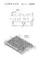
- FIG. 1 of the accompanying drawingsis a front view of that microsample holder and carrier.
- carrier 10is comprised of a generally rectangular base 12 having a pair of arms 14 and 16 extending upwardly from a top wall 18 of the base.
- base 12 and arms 14, 16are formed of one-piece unitary construction of, for example, metal, plastic or other materials normally used to construct conventional cuvette supports.
- the length, height and width of the carrierare equal to the length, height and width of conventional cuvette supports and, thus, the external dimensions of carrier 10 are substantially identical to the external dimensions of the conventional cuvette support.
- Carrier 10is adapted to carry a microsample holder 20 that is formed as a generally rectangular plate and that is suitably positioned within guide slots (not shown) formed in at least the inner wall of arms 14 and 16. Such guide slots function to position and properly align plate 20 which is easily inserted from above carrier 10 and removed therefrom.
- Plate 20is formed with two sets of retaining elements, such as one row of four retaining elements 22, 24, 26 and 28 and another, aligned row of retaining elements 32, 34, 36 and 38. These retaining elements all are of circular shape having diameters on the order of about 3 mm, each retaining element being capable of retaining a 5-10 ⁇ l sample of liquid to be analyzed.
- the surfaces of plate 20 other than the circular areasmay be coated with a thin layer of hydrophobic material to assure retention of the liquid samples within the circular areas.
- Each circular sample-retaining areamay be formed as a relatively thin flat dish.
- Reagents or biologicalsmay be pre-anchored to the circular surfaces of such dishes so that, when liquid samples are applied, the samples come into contact with pre-anchored reagents or biologicals, resulting in onboard, uninterrupted reactions.
- plate 20may be prepared with reactants in advance of use, to await the application of small sample drops to the thus-prepared retaining elements.
- microtitration plate 40is comprised of a generally rectangular stage 42 which supports a holder 44 in which an array of microwells 46 is disposed.
- the overall dimensions of microtitration plate 40are seen to be a length l, a width w and an overall height h from the bottom of stage 42 to the common upper surface of microwells 46.
- 96 microwellsare provided in holder 44, these microwells being disposed in an 8 ⁇ 12 array.
- the microtitration plate illustrated in FIG. 2typically is used with a reader of the type mentioned in the beginning portion of the instant specification.
- the readerserves to analyze liquid samples contained in respective ones of the microwells for measuring the presence of specific biological and biochemical entities, such as particular proteins or the like.
- Each microwellhas a capacity on the order of about 200 ⁇ l; and in some instances, the amount of liquid sample to be measured might not be available in sufficient quantity to fill a microwell.
- Rinsing of the microwells during the operation of the test procedureis often necessary to remove therefrom all free remnants of the liquid sample that had been previously added. This rinsing procedure is quite time-consuming and difficult.
- the microtitration plate shown in FIG. 2has been found to be less than satisfactory in observing or analyzing biological substances attached to the bottom and vertical walls of microwells 46. Although such substances may be observed under low magnification if they adhere to the floor of the microwell, the fact that the walls of the microwells extend in a direction substantially parallel to the light beam of the conventional microscope tends to prevent effective observation of the biological particles on the walls of the microwells. If attached to the planar well-bottom, biologic particles still cannot be examined under high magnification since the walls of the well do not permit the microscope objective to be positioned sufficiently close to the particles to obtain proper focus.
- microtitration plate supports for use with readers, sample-loaders and the likehave been developed for use with standardized microtitration plates having dimensions l, w and h, as illustrated in FIG. 2.
- the present inventionprovides an alternative system exhibiting the same overall dimensions l, w and h as the conventional microtitration plate for use with the microtitration plate support that normally is used with microtitration plate 40.
- the present inventionis compatible with conventional microtitration plate readers, sample-loaders, and the like.
- FIG. 3Ais a top plan view of this embodiment and FIG. 4 is a perspective view thereof.
- This embodimentis comprised of a base 50 formed as a frame 52 and frame portions designated top portion 54, bottom portion 56, left portion 58 and right portion 60, as viewed in the drawings.
- the framemay be formed of plastic, metal, or the like, and is of suitable rigidity and strength to support plural tiles and to cooperate with conventional microtitration plate supports.
- a pair of support ledges 62 and 64extend toward the interior of frame 52 from top and bottom frame portions 54 and 56, respectively.
- a support ledgemay extend inwardly from each respective portion (i.e. from the top, bottom, left and right portions) of frame 52.
- a pair of support ledgesare needed for the successful implementation of the present invention.
- Frame 52exhibits a length l and a width w substantially equal to length l and width w of microtitration plate 40 (FIG. 2).
- Frame 52also exhibits a height h which is seen to be substantially equal to the height h of the conventional microtitration plate.
- the thickness, or height, of each support ledge 62 and 64is less than height h and, thus, each support ledge is seen to be depressed below upper (or top) surface 96 of frame 52. That is, the support ledges are recessed with respect to the top surface of the frame.
- guide elementsare provided for a purpose soon to be explained. In FIGS. 3A and 4, these guide elements are illustrated as being disposed in pairs comprised of guide elements 66, 68, guide elements 70, 72 and guide elements 74, 76.
- the illustrated guide elementsare formed as projections which extend upwardly from support ledges 62 and 64.
- Base 50is used to support a plurality of tiles 86, 88, 90 and 92 in the embodiment illustrated in FIGS. 3A and 4.
- Each tilesuch as tile 86, is formed as a relatively thin flat sheet constructed of glass, plastic, quartz, or the like. The thickness of the tile is approximately equal to the amount by which support ledges 62 and 64 are depressed below top surface 96 of frame 52.
- Each tileis formed with an array of retaining elements 94 matching the positions of the microtitration plate wells, the retaining elements preferably being constructed as relatively thin flat dishes in the tile.
- each tileis of a length such that the opposite edges thereof are supported on support ledges 62 and 64, respectively.
- the pairs of guide elements 66, 68; 70, 72; and 74, 76are seen to separate adjacent tiles. More particularly, guide elements 66, 68 separate tiles 86 and 88; guide elements 70, 72 separate tiles 88 and 90; and guide elements 74, 76 separate tiles 90 and 92. It will be appreciated, therefore, that the guide elements serve to properly position (or guide) each of tiles 86, 88, 90 and 92 in the base or frame 52.
- Tile 86(as well as tiles 88, 90 and 92) is provided with a 3 ⁇ 8 array of retaining elements 94.
- the resultant array of retaining elementsis seen to be an 8 ⁇ 12 array substantially similar to the 8 ⁇ 12 array of microwells 46 of the conventional microtitration plate 40 shown in FIG. 2.
- One portion of frame 52such as bottom portion 56 thereof, is provided with cut outs 78, 80, 82 and 84, these cut outs serving as finger slots, each cut out being generally centrally aligned with a respective one of tiles 86, 88, 90 and 92.
- These cut outsare seen to be recesses in bottom portion 56 of frame 52 and are adapted to receive a user's finger which, when inserted into a respective cut out is disposed adjacent a supported tile. This facilitates the removal of that tile from frame 52.
- the depth of each cut outis greater than the thickness of a tile, whereupon at least the end portion of the user's finger may be inserted beneath the tile to permit easy removal thereof when the user moves his finger in the upward direction. In this manner, a tile may be easily removed from frame 52 to permit replacement thereof by a fresh tile.
- Each of retaining elements 94that is, each of the thin flat dishes, is circular and, preferably, exhibits a diameter of 3 mm.
- each retaining element, or dishrequires a relatively small amount of liquid sample, for example, on the order of 5-10 ⁇ l. It is seen that this quantity of liquid sample is significantly less than the 100-200 ⁇ l volumes heretofore required by microwells 46 of the conventional microtitration plate (FIG. 2). As a result, there is a substantial saving in the amount of liquid sample that must be prepared or that is available for use with the tile of the present invention.
- one (or both) surface of each tilemay be coated with a relatively permanent, water-repellant material with the retaining elements being maintained substantially free of that water-repellant material.
- localized reactionsmay take place within small drops of reaction liquids in the retaining elements, that is, on the surfaces of the thin flat dishes.
- the particular type of localized reaction that takes placeis dependent upon the entity being analyzed and the type of analysis that is performed. Examples of such analyses include the determination of protein concentration, the detection of antigens or antibodies by immunoenzymatic procedures, and the like.
- selected biological substancessuch as proteins
- selected biological substancesmay be anchored permanently to selected ones (or all) of the thin flat dishes provided in a particular tile.
- a biotin bridgemay be formed between that protein and the surface of the dish or retaining element.
- Reactive biological substancesmay be temporarily anchored to a thin flat dish by coating the clean surface of that dish with a permanent, microscopically thin film of material (such as silicon dioxide, or the like) which serves to non-permanently anchor a desired biological substance thereto.
- This biological substancepreferably is dry and remains dry until it is released from its temporary anchorage by the addition thereto of a liquid sample or reagent. This temporary anchoring of dry substances to the tile permits such substances to be safely stored until release due to activation arising out of the addition thereto of a water-containing liquid sample.
- the central portion of frame 52may be completely cut out, thus adding to the ease of removal of tiles 86, 88, 90 and 92 merely by pushing upwardly against those holders from below the frame.
- a solid lower surface of frame 52may remain, this lower surface preventing the inadvertent loss of a tile that may be carelessly or errantly disposed in the frame. While such a lower surface prevents inadvertent damage to the tiles, it reduces the ease by which a tile may be removed from the illustrated base.
- a central ribmay be disposed within frame 52 extending from left portion 58 to right portion 60, this central rib being depressed below top surface 96 by substantially the same amount as support ledges 62 and 64, and this central rib serving substantially the same purpose as the support ledges.
- a tilemay be of approximately half the overall length of tile 86, such a shortened tile being supported between the aforementioned central rib and one of support ledges 62 and 64.
- eight such reduced size tilesmay be employed, each being individually removable from frame 52.
- Each such tilethus may be provided with a 3 ⁇ 4 array (as opposed to the illustrated 3 ⁇ 8 array) of retaining elements, thereby adding to the flexibility of use of the illustrated apparatus. That is, rather than substitute a 3 ⁇ 8 tile for separate analyzing runs, all that may be necessary is the substitution of a smaller 3 ⁇ 4 tile if a smaller number of samples is to be analyzed.
- FIGS. 3A and 3BA side-by-side comparison of the present invention with a conventional microtitration plate is illustrated by the juxtaposed devices shown in FIGS. 3A and 3B. It is seen that the overall dimensions l, w and h of both devices are the same; and that retaining elements 94 provided on tiles 86, 88, 90 and 92 occupy substantially the same positions as microwells 46.
- the conventional reading and liquid-sample loading apparatus normally used with conventional microtitration platesmay be used with the base and tiles of the present invention. That is, base 50 is seen to be compatible with existing, conventional microtitration plate support apparatus.
- frame 52may be used with a single tile having, for example, an 8 ⁇ 12 array of retaining elements. That is, a single tile may be used in place of the four individual tiles that comprise the microcircle system illustrated in FIG. 3A.
- cut outs 78, 80, 82 and 84are illustrated in FIGS. 3A and 4, it will be appreciated that, if desired, only a single such cut out may be present. If four tiles are supported at one time by frame 52, it will be recognized that the removal of one facilitates the easy removal of the remaining three. Consequently, only one cut out need be provided as a finger slot to facilitate the removal of that first tile.
- cut outs 78, 80, 82 and 84have been described above as extending to a depth beneath support ledge 64, it is appreciated that, if desired, such cut outs may extend merely to support ledge 64. Also, although each cut out is seen to be generally centered with respect to a respective tile, the particular positioning of the cut out may vary, as desired. Such central disposition is not necessary to the successful practice of the present invention.
- FIG. 5An alternative embodiment of the present invention is illustrated in FIG. 5.
- This embodimentdiffers from that described above in conjunction with FIGS. 3A and 4 in that base 50' of the FIG. 5 embodiment is adapted to support only a single tile 86 rather than the plural tiles discussed above.
- a plurality of such bases 50', each supporting a respective tilemay be positioned side-by-side in a conventional microtitration plate support in place of the conventional microtitration plate 40.
- the same reference numeralshave been used (with primes) as have been used previously to identify similar parts.
- a further detailed but duplicative discussion of the embodiment shown in FIG. 5need not be provided.
- cut out 78'is disposed in bottom portion 56' of frame 52'.
- additional cut outs 80', 82' and 84', 85'may be provided in the vicinity of the respective corners of tile 86 when the latter is supported on support ledges 62' and 64'.
- a central ribsimilar to the aforementioned central rib that may be added to the embodiment shown in FIGS. 3A and 4, may extend between left portion 58' and right portion 60' to carry out the same function as support ledges 62' and 64'.
- tile 86may be formed as two separate tiles, each of approximately half the size of the illustrated tile. It is appreciated that each such tile of reduced size is supported between the aforementioned central rib and a respective one of support ledges 62' and 64'.
- corner cut outs 80', 82', 84' and 85'are useful in facilitating the removal of a tile from frame 52'. If desired, such corner cut outs may be omitted.
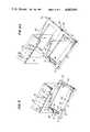
- FIGS. 6A-6CYet another embodiment of the present invention is illustrated in FIGS. 6A-6C.
- This embodimentis comprised of a base 100 formed of two separate frame sections 102 and 104, each section being referred to herein simply as a frame.
- Frames 102 and 104are of substantially identical construction and dimensions, and it is seen that one relatively long side of frame 102 is hingedly connected to a similarly long side of frame 104 by means of a hinge 116.
- This hingemay be formed of thin flexible plastic material or other means by which the two frames may be hingedly connected to each other.
- Hinge 116serves as a pivot axis about which either or both frames are rotatable between an open position, as illustrated in FIG. 6A, to a closed position, as illustrated in FIG. 6C. When in this closed position, it is appreciated that frame 104 is disposed atop frame 102.
- each frame 102 and 104When frames 102 and 104 are disposed in the closed position illustrated in FIG. 6C, that is, when frame 104 is disposed atop frame 102, the height h of the combined frames is seen to be equal to the height h of the conventional microtitration plate 40 (FIG. 2).
- each frame 102 and 104may exhibit a height that is substantially equal to h/2.
- Each of frames 102 and 104may be of substantially the same configuration as frame 52' shown in FIG. 5.
- the length of each frame lpreferably is substantially equal to the length l of the conventional microtitration plate.
- the width of each framemay be approximately equal to a submultiple of the width of the conventional microtitration plate. For example, if the width of each frame is approximately equal to w/4, four closed frames (as shown in FIG. 6C) may be disposed side-by-side in the conventional microtitration plate support.
- the left and right portions 58' and 60' of each framewill be quite thin in order to approximate the width w/4.
- Each of frames 102 and 104is designed to receive and support a respective tile.
- frame 102is provided with a pair of oppositely disposed support ledges 106 and 108 which, as illustrated, and consistent with the foregoing embodiments, extend inwardly from opposite sides of the frame.
- the height of each support ledge 106, 108is seen to be less than the height of frame 102 and, thus, these support ledges are depressed below top surface 128 of this frame.
- a cut out 110is disposed in top surface 128 at, for example, the bottom portion of the frame.
- Cut out 110is seen to extend downwardly to support ledge 106 and is designed to receive the user's finger which, when positioned adjacent tile 112, permits the removal of that tile from frame 102.
- the tileis provided with retaining elements 114 similar to aforedescribed retaining elements 94.
- frame 104may be pivoted about hinge 116, as shown in FIG. 6B, to the closed position illustrated in FIG. 6C. It is seen that frame 104 is provided with support ledges 118 and 120, similar to aforementioned support ledges 106 and 108. Frame 104 also is provided with a cut out 122 that is similar to aforementioned cut out 110.
- Tile 124is designed to be positioned within frame 104 and supported by oppositely located support ledges 118 and 120.
- Tile 124may be substantially identical to aforementioned tile 112 and, when these tiles are supported in their respective frames, retaining elements 114 of one tile are aligned with retaining elements 126 of the other. Furthermore, when the respective tiles are supported on their respective support ledges, the tiles are spaced apart by a distance such that a liquid sample that may be contained on one of retaining elements 114 contacts an aligned one of retaining elements 126 so as to form a liquid bridge therebetween.
- top surface 128 of frame 102 and top surface 130 of frame 104face in opposite directions.
- tile 112may be disposed in frame 102 when the frames are in their open position; and tile 124 may be disposed in frame 104 when the frames are in their closed position.
- liquid samplesmay be added to desired retaining elements 114 of tile 112 after frames 102 and 104 are pivoted to their closed position, but before tile 124 is disposed in frame 104. Then, tile 124 is disposed in frame 104 such that the aligned retaining elements of both tiles exhibit a face-to-face relationship. As a result, the liquid samples located on the lower tile 112 contact the thin flat dishes of the aligned retaining elements 126 of the upper tile 124, thereby forming a liquid bridge, or stable column, of liquid sample between the aligned, opposing dishes. A chemical or other reaction occurring in this bridge may be measured with conventional instruments.
- reagentsmay be permanently anchored to all or selected ones of the retaining dishes.
- reactive biological substancesmay be temporarily anchored, or attached, to these dishes such that the reactive biological substances remain dry until activated by the addition thereto of water-containing samples or other liquids.
- the reactive biological substancesmay be anchored to lower tile 112 and such adherence to upper tile 124 may be avoided by creating a "non-stick" barrier between the dried biological substances and the surfaces of the retaining dishes of the upper tile.
- the test washing procedure performed on the tiles used in the present inventionis much simpler and quicker than the cleansing operation heretofore needed for conventional microtitration plates.
- Other advantages of the present inventionhave been discussed above and still further advantages will be readily appreciated by those of ordinary skill in the art.
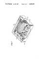
- the combination of base and tilesmay be packaged, together with containers of various reagents, in a "kit".
- This kit 150shown in FIG.
- reagents 158may be used for different assays or analyses, and the manner in which those reagents should be applied to the retaining elements, or dishes, of each tile.
- the rack, tiles, booklet and reagentsmay be housed in container 160.
- a micropipettealso may be included for purposes of reagent application.
Landscapes
- Physics & Mathematics (AREA)
- Health & Medical Sciences (AREA)
- Life Sciences & Earth Sciences (AREA)
- Chemical & Material Sciences (AREA)
- Analytical Chemistry (AREA)
- Biochemistry (AREA)
- General Health & Medical Sciences (AREA)
- General Physics & Mathematics (AREA)
- Immunology (AREA)
- Pathology (AREA)
- Automatic Analysis And Handling Materials Therefor (AREA)
- Sampling And Sample Adjustment (AREA)
Abstract
Description
Claims (31)
Priority Applications (1)
| Application Number | Priority Date | Filing Date | Title |
|---|---|---|---|
| US06/775,582US4682891A (en) | 1985-05-31 | 1985-09-13 | Microcircle system |
Applications Claiming Priority (2)
| Application Number | Priority Date | Filing Date | Title |
|---|---|---|---|
| US06/739,969US4682890A (en) | 1985-05-31 | 1985-05-31 | Microsample holder and carrier therefor |
| US06/775,582US4682891A (en) | 1985-05-31 | 1985-09-13 | Microcircle system |
Related Parent Applications (1)
| Application Number | Title | Priority Date | Filing Date |
|---|---|---|---|
| US06/739,969Continuation-In-PartUS4682890A (en) | 1985-05-31 | 1985-05-31 | Microsample holder and carrier therefor |
Publications (1)
| Publication Number | Publication Date |
|---|---|
| US4682891Atrue US4682891A (en) | 1987-07-28 |
Family
ID=27113608
Family Applications (1)
| Application Number | Title | Priority Date | Filing Date |
|---|---|---|---|
| US06/775,582Expired - Fee RelatedUS4682891A (en) | 1985-05-31 | 1985-09-13 | Microcircle system |
Country Status (1)
| Country | Link |
|---|---|
| US (1) | US4682891A (en) |
Cited By (76)
| Publication number | Priority date | Publication date | Assignee | Title |
|---|---|---|---|---|
| USD300245S (en) | 1986-08-14 | 1989-03-14 | Sherwood Medical Company | Microbiological test tray carrier |
| US4817785A (en)* | 1985-03-01 | 1989-04-04 | Sherwood Medical Company | Automated microbiological testing apparatus |
| USD301167S (en) | 1987-02-27 | 1989-05-16 | Allelix Limited | Immunoassay tray |
| US4919894A (en)* | 1988-05-23 | 1990-04-24 | Robert Daniel | Multiple sample holder indexing means and method of using same |
| US4981361A (en)* | 1988-03-03 | 1991-01-01 | Omron Tataesi Electronics Co. | Color comparison device having a color sample-bonding wheel which permits easy removal of a color sample sticker |
| DE9015317U1 (en)* | 1990-11-07 | 1991-03-14 | Panitz, Norbert, Dr., 6500 Mainz | Double plate |
| US5213505A (en)* | 1991-06-24 | 1993-05-25 | Laipply Thomas C | Variable color matrix device |
| US5221410A (en)* | 1991-10-09 | 1993-06-22 | Schering Corporation | Crystal forming device |
| US5320808A (en)* | 1988-08-02 | 1994-06-14 | Abbott Laboratories | Reaction cartridge and carousel for biological sample analyzer |
| US5358692A (en)* | 1993-09-02 | 1994-10-25 | Reynolds Douglas W | Tissue cassette holder |
| US5484731A (en)* | 1993-05-26 | 1996-01-16 | Becton, Dickinson And Company | Multiwell in-vitro fertilization plate |
| US5638170A (en)* | 1994-06-07 | 1997-06-10 | Hudson Control Group, Inc. | Punched carrier specimen sample processor |
| US5650125A (en)* | 1992-10-14 | 1997-07-22 | Bosanquet; Andrew George | Method and apparatus for conducting tests |
| US5716798A (en)* | 1992-09-22 | 1998-02-10 | Becton Dickinson And Company | Enhanced detection of microorganisms in samples |
| US5774214A (en)* | 1996-12-12 | 1998-06-30 | Photometrics, Ltd. | Multi-mode imaging apparatus for radiation-emitting or absorbing samples |
| US5784193A (en)* | 1996-06-28 | 1998-07-21 | Ferguson; Gary W. | Microscope slide with removable layer and method |
| WO1999006589A1 (en)* | 1997-08-01 | 1999-02-11 | Minnesota Mining And Manufacturing Company | Method and devices for detecting and enumerating microorganisms |
| US6018388A (en)* | 1998-02-18 | 2000-01-25 | Nawracala; Bernd | Microtiter plate |
| US6118582A (en)* | 1999-07-12 | 2000-09-12 | Immuno Concepts, Inc. | Slide holder |
| US6157456A (en)* | 1997-03-11 | 2000-12-05 | Hvass; Per | Cuvette for spectrophotometrical analysis |
| US6174699B1 (en) | 1999-03-09 | 2001-01-16 | 3M Innovative Properties Company | Disc assay device with inoculation pad and methods of use |
| USD454202S1 (en) | 1998-01-12 | 2002-03-05 | Aurora Biosciences Corporation | Multi-well platform |
| US6391578B2 (en) | 1997-04-09 | 2002-05-21 | 3M Innovative Properties Company | Method and devices for partitioning biological sample liquids into microvolumes |
| US6399394B1 (en) | 1999-06-30 | 2002-06-04 | Agilent Technologies, Inc. | Testing multiple fluid samples with multiple biopolymer arrays |
| US20030054543A1 (en)* | 1997-06-16 | 2003-03-20 | Lafferty William Michael | Device for moving a selected station of a holding plate to a predetermined location for interaction with a probe |
| US6558627B1 (en)* | 1997-08-08 | 2003-05-06 | Aventis Pharma Deutschland Gmbh | Temperature control apparatus and method for pipetting robot |
| US20030143630A1 (en)* | 1998-05-20 | 2003-07-31 | Selecticide Corporation | Apparatus and method for synthesizing |
| US6605473B1 (en)* | 1998-12-18 | 2003-08-12 | Symyx Technologies, Inc. | Method for characterizing libraries of different materials using x-ray scattering |
| US20030150379A1 (en)* | 2002-01-18 | 2003-08-14 | Goodwin Richard H. | Crystal forming apparatus and method for using same |
| DE10203940A1 (en)* | 2002-02-01 | 2003-08-21 | Fraunhofer Ges Forschung | Plate for use in cryogenic storage of biological specimens has wells, into which specimens are placed, fits into cover in same way as drawer of matchbox, and is held in position by e.g. studs and recesses |
| US20030179378A1 (en)* | 2002-03-22 | 2003-09-25 | Lafferty William Michael | Method for intensifying the optical detection of samples that are held in solution in the through-hole wells of a holding tray |
| US20030184745A1 (en)* | 2000-09-01 | 2003-10-02 | Holger Deppe | Positioning device for microtiter plates |
| US20030211555A1 (en)* | 1992-07-10 | 2003-11-13 | Jaffe Russell M. | Assay for evaluation of cellular response to allergens |
| US6696286B1 (en) | 1997-04-09 | 2004-02-24 | 3M Innovative Properties Company | Method and devices for detecting and enumerating microorganisms |
| US20040098204A1 (en)* | 1999-10-26 | 2004-05-20 | Genometrix Genomics, Inc. | Selective retreival of biological samples from an integrated repository |
| US6743633B1 (en)* | 1998-01-12 | 2004-06-01 | Massachusetts Institute Of Technology | Method for performing microassays |
| US20040171141A1 (en)* | 2003-02-28 | 2004-09-02 | Leica Mikrosysteme Gmbh | Transport container for slides for immunological labeling for thin tissue sections |
| US20050056205A1 (en)* | 2002-01-18 | 2005-03-17 | Goodwin Richard H. | Crystal forming apparatus and method for using same |
| RU2248569C2 (en)* | 2002-05-24 | 2005-03-20 | Захарченко Виктор Николаевич | Microtitration method |
| US20050148066A1 (en)* | 2000-02-18 | 2005-07-07 | O'keefe Matthew | Apparatus and methods for parallel processing of micro-volume liquid reactions |
| US6918738B2 (en) | 2002-03-11 | 2005-07-19 | Diversa Corporation | Stackable sample holding plate with robot removable lid |
| US20050214854A1 (en)* | 2002-05-31 | 2005-09-29 | Dahm Sueann C | Testing multiple fluid samples with multiple biopolymer arrays |
| WO2005114104A1 (en)* | 2004-05-07 | 2005-12-01 | P.A.L.M. Microlaser Technologies Ag | Microscope table and insert |
| US20060105453A1 (en)* | 2004-09-09 | 2006-05-18 | Brenan Colin J | Coating process for microfluidic sample arrays |
| US20060140821A1 (en)* | 2004-12-17 | 2006-06-29 | Rosso Victor W | Powder X-ray diffraction sample holder |
| US20070160280A1 (en)* | 2004-05-11 | 2007-07-12 | P.A.L.M. Microlaser Technologies Gmbh | Method for processing a material by means of a laser irradiation and control system |
| US20080108112A1 (en)* | 2000-02-18 | 2008-05-08 | Biotrove, Inc. | Apparatus and methods for parallel processing of micro-volume liquid reactions |
| US20080156640A1 (en)* | 2006-09-20 | 2008-07-03 | Bio-Rad Laboratories, Inc. | High-throughput electroporation chamber with functional lid for risk reduction |
| US20080220481A1 (en)* | 2005-09-06 | 2008-09-11 | Finnzymes Instruments Oy | Sample Plate Assembly and Method of Processing Biological Samples |
| US20080254517A1 (en)* | 2005-09-06 | 2008-10-16 | Finnzymes Instruments Oy | Thermal Cycler With Optimized Sample Holder Geometry |
| WO2008109588A3 (en)* | 2007-03-08 | 2008-12-04 | Bio Rad Laboratories | Composite electroporation plate with interchangeable well inserts |
| US7547556B2 (en) | 1998-01-12 | 2009-06-16 | Massachusetts Institute Of Technology | Methods for filing a sample array by droplet dragging |
| US7682565B2 (en) | 2002-12-20 | 2010-03-23 | Biotrove, Inc. | Assay apparatus and method using microfluidic arrays |
| DE10223412B4 (en)* | 2002-05-25 | 2011-11-10 | Leica Biosystems Nussloch Gmbh | Tableau for holding cassettes and / or slides for histological or cytological preparations |
| US8105554B2 (en) | 2004-03-12 | 2012-01-31 | Life Technologies Corporation | Nanoliter array loading |
| US8277753B2 (en) | 2002-08-23 | 2012-10-02 | Life Technologies Corporation | Microfluidic transfer pin |
| CN104830681A (en)* | 2014-02-09 | 2015-08-12 | 李保伟 | Cell culture glass slide system |
| US20170056880A1 (en)* | 2015-08-26 | 2017-03-02 | EMULATE, Inc. | Fluid connections using guide mechanisms |
| RU169531U1 (en)* | 2016-04-22 | 2017-03-22 | государственное бюджетное образовательное учреждение высшего профессионального образования "Кемеровская государственная медицинская академия" Министерства здравоохранения Российской Федерации | HISTOLOGICAL GRILLE FOR PRODUCTION OF DRUGS |
| USD848638S1 (en)* | 2017-05-31 | 2019-05-14 | Advanced Biotechnologies Limited | Multi-well plate assembly |
| WO2020208081A1 (en)* | 2019-04-08 | 2020-10-15 | Leica Microsystems Cms Gmbh | Device for holding specimens in a microscope |
| US20230085933A1 (en)* | 2021-09-21 | 2023-03-23 | The Government of the United States of America, as represented by the Secretary of Homeland Security | Media holder for sample preparation |
| USD1004126S1 (en)* | 2022-03-07 | 2023-11-07 | Michael Thomas Hendrikx | Instrument and utensil for medical or laboratory diagnosis |
| USD1013205S1 (en)* | 2022-05-26 | 2024-01-30 | Singular Genomics Systems, Inc. | Microplate assembly |
| USD1013204S1 (en)* | 2022-05-26 | 2024-01-30 | Singular Genomics Systems, Inc. | Microplate assembly |
| USD1021136S1 (en)* | 2021-12-14 | 2024-04-02 | Agilent Technologies, Inc. | Booster plate |
| USD1021135S1 (en)* | 2022-05-31 | 2024-04-02 | Tecan Trading Ag | Tray for pipetting tips |
| USD1021134S1 (en)* | 2021-11-03 | 2024-04-02 | Sg Medical, Inc. | Well plate |
| USD1022695S1 (en)* | 2021-06-23 | 2024-04-16 | Worthington Industries, Inc. | Tray |
| USD1030489S1 (en)* | 2022-05-26 | 2024-06-11 | Solid Strategic Services Llc | Cartridge box foam insert |
| USD1036695S1 (en)* | 2022-09-15 | 2024-07-23 | Nicoya Lifesciences Inc. | Analysis cartridge top plate |
| USD1036697S1 (en)* | 2022-09-15 | 2024-07-23 | Nicoya Lifesciences Inc. | Analysis cartridge cover plate |
| USD1036696S1 (en)* | 2022-09-15 | 2024-07-23 | Nicoya Lifesciences Inc. | Analysis cartridge cover plate |
| US12070731B2 (en) | 2004-08-04 | 2024-08-27 | Life Technologies Corporation | Methods and systems for aligning dispensing arrays with microfluidic sample arrays |
| USD1050892S1 (en)* | 2022-05-12 | 2024-11-12 | Prince Sterilization Services, LLC | Container carrier |
| US12440848B2 (en) | 2025-01-15 | 2025-10-14 | The Government of the United States of America, represented by the Secretary of Homeland Security | Media holders with cross members for sample preparation |
Citations (9)
| Publication number | Priority date | Publication date | Assignee | Title |
|---|---|---|---|---|
| US2561339A (en)* | 1944-01-10 | 1951-07-24 | Chediak Alejandro | Apparatus for laboratory investigations |
| US3415361A (en)* | 1966-12-22 | 1968-12-10 | Miles Lab | Test device and container therefor |
| US3736042A (en)* | 1971-05-05 | 1973-05-29 | Clinical Sciences Inc | Microscope slide assembly |
| US3992265A (en)* | 1975-12-31 | 1976-11-16 | American Cyanamid Company | Antibiotic susceptibility testing |
| US4299920A (en)* | 1979-01-19 | 1981-11-10 | Peters J Hinrich | Biological receptacle |
| US4319841A (en)* | 1979-03-01 | 1982-03-16 | Kommandiittiyhtio Finnpipette Osmo A. Suovaniemi | Micro-cuvette unit for facilitating the identification of samples |
| WO1984002775A1 (en)* | 1983-01-07 | 1984-07-19 | Labsystems Oy | Microcuvette set |
| DE3336738A1 (en)* | 1983-10-08 | 1985-05-02 | Wolfgang Dr. 7400 Tübingen Heizmann | TITER PLATE |
| EP0146143A2 (en)* | 1983-12-20 | 1985-06-26 | Showa Yakuhin Kako Co., Ltd. | Simplified detection implement |
- 1985
- 1985-09-13USUS06/775,582patent/US4682891A/ennot_activeExpired - Fee Related
Patent Citations (9)
| Publication number | Priority date | Publication date | Assignee | Title |
|---|---|---|---|---|
| US2561339A (en)* | 1944-01-10 | 1951-07-24 | Chediak Alejandro | Apparatus for laboratory investigations |
| US3415361A (en)* | 1966-12-22 | 1968-12-10 | Miles Lab | Test device and container therefor |
| US3736042A (en)* | 1971-05-05 | 1973-05-29 | Clinical Sciences Inc | Microscope slide assembly |
| US3992265A (en)* | 1975-12-31 | 1976-11-16 | American Cyanamid Company | Antibiotic susceptibility testing |
| US4299920A (en)* | 1979-01-19 | 1981-11-10 | Peters J Hinrich | Biological receptacle |
| US4319841A (en)* | 1979-03-01 | 1982-03-16 | Kommandiittiyhtio Finnpipette Osmo A. Suovaniemi | Micro-cuvette unit for facilitating the identification of samples |
| WO1984002775A1 (en)* | 1983-01-07 | 1984-07-19 | Labsystems Oy | Microcuvette set |
| DE3336738A1 (en)* | 1983-10-08 | 1985-05-02 | Wolfgang Dr. 7400 Tübingen Heizmann | TITER PLATE |
| EP0146143A2 (en)* | 1983-12-20 | 1985-06-26 | Showa Yakuhin Kako Co., Ltd. | Simplified detection implement |
Cited By (132)
| Publication number | Priority date | Publication date | Assignee | Title |
|---|---|---|---|---|
| US4817785A (en)* | 1985-03-01 | 1989-04-04 | Sherwood Medical Company | Automated microbiological testing apparatus |
| USD300245S (en) | 1986-08-14 | 1989-03-14 | Sherwood Medical Company | Microbiological test tray carrier |
| USD301167S (en) | 1987-02-27 | 1989-05-16 | Allelix Limited | Immunoassay tray |
| US4981361A (en)* | 1988-03-03 | 1991-01-01 | Omron Tataesi Electronics Co. | Color comparison device having a color sample-bonding wheel which permits easy removal of a color sample sticker |
| US4919894A (en)* | 1988-05-23 | 1990-04-24 | Robert Daniel | Multiple sample holder indexing means and method of using same |
| US5320808A (en)* | 1988-08-02 | 1994-06-14 | Abbott Laboratories | Reaction cartridge and carousel for biological sample analyzer |
| DE9015317U1 (en)* | 1990-11-07 | 1991-03-14 | Panitz, Norbert, Dr., 6500 Mainz | Double plate |
| US5213505A (en)* | 1991-06-24 | 1993-05-25 | Laipply Thomas C | Variable color matrix device |
| US5221410A (en)* | 1991-10-09 | 1993-06-22 | Schering Corporation | Crystal forming device |
| US20030211555A1 (en)* | 1992-07-10 | 2003-11-13 | Jaffe Russell M. | Assay for evaluation of cellular response to allergens |
| US5716798A (en)* | 1992-09-22 | 1998-02-10 | Becton Dickinson And Company | Enhanced detection of microorganisms in samples |
| US5650125A (en)* | 1992-10-14 | 1997-07-22 | Bosanquet; Andrew George | Method and apparatus for conducting tests |
| US5484731A (en)* | 1993-05-26 | 1996-01-16 | Becton, Dickinson And Company | Multiwell in-vitro fertilization plate |
| US5358692A (en)* | 1993-09-02 | 1994-10-25 | Reynolds Douglas W | Tissue cassette holder |
| US5638170A (en)* | 1994-06-07 | 1997-06-10 | Hudson Control Group, Inc. | Punched carrier specimen sample processor |
| US5784193A (en)* | 1996-06-28 | 1998-07-21 | Ferguson; Gary W. | Microscope slide with removable layer and method |
| US5774214A (en)* | 1996-12-12 | 1998-06-30 | Photometrics, Ltd. | Multi-mode imaging apparatus for radiation-emitting or absorbing samples |
| US6157456A (en)* | 1997-03-11 | 2000-12-05 | Hvass; Per | Cuvette for spectrophotometrical analysis |
| US6696286B1 (en) | 1997-04-09 | 2004-02-24 | 3M Innovative Properties Company | Method and devices for detecting and enumerating microorganisms |
| US6391578B2 (en) | 1997-04-09 | 2002-05-21 | 3M Innovative Properties Company | Method and devices for partitioning biological sample liquids into microvolumes |
| US20030054543A1 (en)* | 1997-06-16 | 2003-03-20 | Lafferty William Michael | Device for moving a selected station of a holding plate to a predetermined location for interaction with a probe |
| WO1999006589A1 (en)* | 1997-08-01 | 1999-02-11 | Minnesota Mining And Manufacturing Company | Method and devices for detecting and enumerating microorganisms |
| US6558627B1 (en)* | 1997-08-08 | 2003-05-06 | Aventis Pharma Deutschland Gmbh | Temperature control apparatus and method for pipetting robot |
| US20030170910A1 (en)* | 1997-08-08 | 2003-09-11 | Aventis Pharma Deutschland Gmbh | Temperature control apparatus and method for pipetting robot |
| USD454202S1 (en) | 1998-01-12 | 2002-03-05 | Aurora Biosciences Corporation | Multi-well platform |
| US7547556B2 (en) | 1998-01-12 | 2009-06-16 | Massachusetts Institute Of Technology | Methods for filing a sample array by droplet dragging |
| US8029745B2 (en) | 1998-01-12 | 2011-10-04 | Massachusetts Institute Of Technology | Systems for filling a sample array by droplet dragging |
| US20040171166A1 (en)* | 1998-01-12 | 2004-09-02 | Massachusetts Institute Of Technology | Method and apparatus for performing microassays |
| US20150126412A1 (en)* | 1998-01-12 | 2015-05-07 | Massachusetts Institute Of Technology | Systems for filling a sample array by droplet dragging |
| US6743633B1 (en)* | 1998-01-12 | 2004-06-01 | Massachusetts Institute Of Technology | Method for performing microassays |
| US6018388A (en)* | 1998-02-18 | 2000-01-25 | Nawracala; Bernd | Microtiter plate |
| US20030143630A1 (en)* | 1998-05-20 | 2003-07-31 | Selecticide Corporation | Apparatus and method for synthesizing |
| US6605473B1 (en)* | 1998-12-18 | 2003-08-12 | Symyx Technologies, Inc. | Method for characterizing libraries of different materials using x-ray scattering |
| US20040017896A1 (en)* | 1998-12-18 | 2004-01-29 | Symyx Technologies, Inc. | Apparatus and method for characterizing libraries of different materials using x-ray scattering |
| US6174699B1 (en) | 1999-03-09 | 2001-01-16 | 3M Innovative Properties Company | Disc assay device with inoculation pad and methods of use |
| US6291202B1 (en) | 1999-03-09 | 2001-09-18 | 3M Innovative Properties Company | Disc assay device with inoculation pad and methods of use |
| US7247497B2 (en) | 1999-06-30 | 2007-07-24 | Agilent Technologies, Inc. | Testing multiple fluid samples with multiple biopolymer arrays |
| US6399394B1 (en) | 1999-06-30 | 2002-06-04 | Agilent Technologies, Inc. | Testing multiple fluid samples with multiple biopolymer arrays |
| US6118582A (en)* | 1999-07-12 | 2000-09-12 | Immuno Concepts, Inc. | Slide holder |
| US20040098204A1 (en)* | 1999-10-26 | 2004-05-20 | Genometrix Genomics, Inc. | Selective retreival of biological samples from an integrated repository |
| US20040142371A1 (en)* | 1999-10-26 | 2004-07-22 | Genometrix Genomics Inc. | Process for requesting biological experiments and for the delivery of experimental information |
| EP1235766A4 (en)* | 1999-11-24 | 2006-05-24 | Aventis Pharma Inc | Apparatus and method for synthesizing combinatorial libraries |
| US8906618B2 (en) | 2000-02-18 | 2014-12-09 | The Board Of Trustees Of The Leland Stanford Junior University | Apparatus and methods for parallel processing of micro-volume liquid reactions |
| US10378049B2 (en) | 2000-02-18 | 2019-08-13 | The Board Of Trustees Of The Leland Stanford Junior University | Apparatus and methods for parallel processing of microvolume liquid reactions |
| US7833719B2 (en) | 2000-02-18 | 2010-11-16 | The Board Of Trustees Of The Leland Stanford Junior University | Apparatus and methods for parallel processing of micro-volume liquid reactions |
| US7604983B2 (en) | 2000-02-18 | 2009-10-20 | Board Of Trustees Of The Leland Stanford Junior University | Apparatus and methods for parallel processing of micro-volume liquid reactions |
| US10227644B2 (en) | 2000-02-18 | 2019-03-12 | The Board Of Trustees Of The Leland Stanford Junior University | Apparatus and methods for parallel processing of microvolume liquid reactions |
| US20080108112A1 (en)* | 2000-02-18 | 2008-05-08 | Biotrove, Inc. | Apparatus and methods for parallel processing of micro-volume liquid reactions |
| US20050148066A1 (en)* | 2000-02-18 | 2005-07-07 | O'keefe Matthew | Apparatus and methods for parallel processing of micro-volume liquid reactions |
| US9518299B2 (en) | 2000-02-18 | 2016-12-13 | The Board Of Trustees Of The Leland Stanford Junior University | Apparatus and methods for parallel processing of micro-volume liquid reactions |
| US20030184745A1 (en)* | 2000-09-01 | 2003-10-02 | Holger Deppe | Positioning device for microtiter plates |
| US20040184977A1 (en)* | 2002-01-18 | 2004-09-23 | Goodwin Richard H. | Crystal forming apparatus and method for using same |
| US7014706B2 (en) | 2002-01-18 | 2006-03-21 | Neuro Probe Incorporated | Crystal forming apparatus and method for using same |
| US20030150379A1 (en)* | 2002-01-18 | 2003-08-14 | Goodwin Richard H. | Crystal forming apparatus and method for using same |
| US20050056205A1 (en)* | 2002-01-18 | 2005-03-17 | Goodwin Richard H. | Crystal forming apparatus and method for using same |
| US7704325B2 (en) | 2002-01-18 | 2010-04-27 | Neuro Probe Incorporated | Crystal forming apparatus and method for using same |
| US7332029B2 (en) | 2002-01-18 | 2008-02-19 | Neuro Probe Incorporated | Crystal forming apparatus and method for using same |
| US20080134963A1 (en)* | 2002-01-18 | 2008-06-12 | Neuro Probe Incorporated | Crystal Forming Apparatus And Method For Using Same |
| US6767401B2 (en) | 2002-01-18 | 2004-07-27 | Neuro Probe Incorporated | Crystal forming apparatus and method for using same |
| DE10203940B4 (en)* | 2002-02-01 | 2006-06-14 | Fraunhofer-Gesellschaft zur Förderung der angewandten Forschung e.V. | Cryoprobe carrier for modular cryostorage storage |
| DE10203940A1 (en)* | 2002-02-01 | 2003-08-21 | Fraunhofer Ges Forschung | Plate for use in cryogenic storage of biological specimens has wells, into which specimens are placed, fits into cover in same way as drawer of matchbox, and is held in position by e.g. studs and recesses |
| US6918738B2 (en) | 2002-03-11 | 2005-07-19 | Diversa Corporation | Stackable sample holding plate with robot removable lid |
| US20030179378A1 (en)* | 2002-03-22 | 2003-09-25 | Lafferty William Michael | Method for intensifying the optical detection of samples that are held in solution in the through-hole wells of a holding tray |
| US20040246484A1 (en)* | 2002-03-22 | 2004-12-09 | Lafferty William Michael | Method for intensifying the optical detection of samples that are held in solution in the through-hole wells of a holding tray |
| US6798520B2 (en) | 2002-03-22 | 2004-09-28 | Diversa Corporation | Method for intensifying the optical detection of samples that are held in solution in the through-hole wells of a holding tray |
| RU2248569C2 (en)* | 2002-05-24 | 2005-03-20 | Захарченко Виктор Николаевич | Microtitration method |
| DE10223412B4 (en)* | 2002-05-25 | 2011-11-10 | Leica Biosystems Nussloch Gmbh | Tableau for holding cassettes and / or slides for histological or cytological preparations |
| US20050214854A1 (en)* | 2002-05-31 | 2005-09-29 | Dahm Sueann C | Testing multiple fluid samples with multiple biopolymer arrays |
| US7537936B2 (en) | 2002-05-31 | 2009-05-26 | Agilent Technologies, Inc. | Method of testing multiple fluid samples with multiple biopolymer arrays |
| US8685340B2 (en) | 2002-08-23 | 2014-04-01 | Life Technologies Corporation | Microfluidic transfer pin |
| US8277753B2 (en) | 2002-08-23 | 2012-10-02 | Life Technologies Corporation | Microfluidic transfer pin |
| US9428800B2 (en) | 2002-12-20 | 2016-08-30 | Life Technologies Corporation | Thermal cycling apparatus and method |
| US7682565B2 (en) | 2002-12-20 | 2010-03-23 | Biotrove, Inc. | Assay apparatus and method using microfluidic arrays |
| US8697452B2 (en) | 2002-12-20 | 2014-04-15 | Life Technologies Corporation | Thermal cycling assay apparatus and method |
| US7410055B2 (en) | 2003-02-28 | 2008-08-12 | Leica Mikrosysteme Gmbh | Transport container for slides for immunological labeling for thin tissue sections |
| DE10309210B4 (en)* | 2003-02-28 | 2006-04-27 | Leica Mikrosysteme Gmbh | Use of a transport container for slides for immunological marking for tissue thin sections |
| US20040171141A1 (en)* | 2003-02-28 | 2004-09-02 | Leica Mikrosysteme Gmbh | Transport container for slides for immunological labeling for thin tissue sections |
| US8105554B2 (en) | 2004-03-12 | 2012-01-31 | Life Technologies Corporation | Nanoliter array loading |
| US10065189B2 (en) | 2004-03-12 | 2018-09-04 | Life Technologies Corporation | Nanoliter array loading |
| US9266108B2 (en) | 2004-03-12 | 2016-02-23 | Life Technologies Corporation | Nanoliter array loading |
| US8545772B2 (en) | 2004-03-12 | 2013-10-01 | Life Technologies Corporation | Nanoliter array loading |
| US10974247B2 (en) | 2004-03-12 | 2021-04-13 | Life Technologies Corporation | Nanoliter array loading |
| US7576912B2 (en) | 2004-05-07 | 2009-08-18 | P.A.L.M. Microlaser Technologies Gmbh | Microscope table and insert |
| WO2005114104A1 (en)* | 2004-05-07 | 2005-12-01 | P.A.L.M. Microlaser Technologies Ag | Microscope table and insert |
| US20070153369A1 (en)* | 2004-05-07 | 2007-07-05 | P.A.L.M. Microlaser Technologies Gmbh | Microscope table and insert |
| US20070160280A1 (en)* | 2004-05-11 | 2007-07-12 | P.A.L.M. Microlaser Technologies Gmbh | Method for processing a material by means of a laser irradiation and control system |
| US7848552B2 (en) | 2004-05-11 | 2010-12-07 | P.A.L.M. Microlaser Technologies Gmbh | Method for processing a material by means of a laser irradiation and control system |
| US11154834B2 (en) | 2004-08-04 | 2021-10-26 | Life Technologies Corporation | Coating process for microfluidic sample arrays |
| US12070731B2 (en) | 2004-08-04 | 2024-08-27 | Life Technologies Corporation | Methods and systems for aligning dispensing arrays with microfluidic sample arrays |
| US10213761B2 (en) | 2004-08-04 | 2019-02-26 | Life Technologies Corporation | Coating process for microfluidic sample arrays |
| US20060105453A1 (en)* | 2004-09-09 | 2006-05-18 | Brenan Colin J | Coating process for microfluidic sample arrays |
| US20060140821A1 (en)* | 2004-12-17 | 2006-06-29 | Rosso Victor W | Powder X-ray diffraction sample holder |
| US9604219B2 (en)* | 2005-09-06 | 2017-03-28 | Thermo Fisher Scientific Oy | Thermal cycler with optimized sample holder geometry |
| US9782777B2 (en)* | 2005-09-06 | 2017-10-10 | Thermo Fisher Scientific Oy | Sample plate assembly and method of processing biological samples |
| US20080220481A1 (en)* | 2005-09-06 | 2008-09-11 | Finnzymes Instruments Oy | Sample Plate Assembly and Method of Processing Biological Samples |
| US20080254517A1 (en)* | 2005-09-06 | 2008-10-16 | Finnzymes Instruments Oy | Thermal Cycler With Optimized Sample Holder Geometry |
| US7943367B2 (en)* | 2006-09-20 | 2011-05-17 | Bio-Rad Laboratories, Inc. | High-throughput electroporation chamber with functional lid for risk reduction |
| US20080156640A1 (en)* | 2006-09-20 | 2008-07-03 | Bio-Rad Laboratories, Inc. | High-throughput electroporation chamber with functional lid for risk reduction |
| US8017381B2 (en) | 2007-03-08 | 2011-09-13 | Bio-Rad Laboratories, Inc. | Composite electroporation plate with interchangeable well inserts |
| WO2008109588A3 (en)* | 2007-03-08 | 2008-12-04 | Bio Rad Laboratories | Composite electroporation plate with interchangeable well inserts |
| CN104830681A (en)* | 2014-02-09 | 2015-08-12 | 李保伟 | Cell culture glass slide system |
| US10689608B2 (en) | 2015-08-26 | 2020-06-23 | EMULATE, Inc. | Droplet fluid connections |
| US11820966B2 (en) | 2015-08-26 | 2023-11-21 | EMULATE, Inc. | Pressure manifold and culture module |
| US20170056880A1 (en)* | 2015-08-26 | 2017-03-02 | EMULATE, Inc. | Fluid connections using guide mechanisms |
| US10913924B2 (en) | 2015-08-26 | 2021-02-09 | EMULATE, Inc. | Controlling pressure |
| US10988722B2 (en) | 2015-08-26 | 2021-04-27 | EMULATE, Inc. | Perfusion manifold assembly |
| US10988721B2 (en) | 2015-08-26 | 2021-04-27 | EMULATE, Inc. | Controlling pressure |
| US10519410B2 (en) | 2015-08-26 | 2019-12-31 | Emulate, Inc | Pressure manifold and culture module |
| US11920114B2 (en) | 2015-08-26 | 2024-03-05 | EMULATE, Inc. | Controlling pressure |
| US11834641B2 (en) | 2015-08-26 | 2023-12-05 | EMULATE, Inc. | Controlling pressure |
| RU169531U1 (en)* | 2016-04-22 | 2017-03-22 | государственное бюджетное образовательное учреждение высшего профессионального образования "Кемеровская государственная медицинская академия" Министерства здравоохранения Российской Федерации | HISTOLOGICAL GRILLE FOR PRODUCTION OF DRUGS |
| USD848638S1 (en)* | 2017-05-31 | 2019-05-14 | Advanced Biotechnologies Limited | Multi-well plate assembly |
| JP2022528175A (en)* | 2019-04-08 | 2022-06-08 | ライカ マイクロシステムズ シーエムエス ゲゼルシャフト ミット ベシュレンクテル ハフツング | A device for holding a sample in a microscope |
| US12326550B2 (en) | 2019-04-08 | 2025-06-10 | Leica Microsystems Cms Gmbh | Device for holding specimens in a microscope |
| WO2020208081A1 (en)* | 2019-04-08 | 2020-10-15 | Leica Microsystems Cms Gmbh | Device for holding specimens in a microscope |
| USD1022695S1 (en)* | 2021-06-23 | 2024-04-16 | Worthington Industries, Inc. | Tray |
| US12201986B2 (en) | 2021-09-21 | 2025-01-21 | The Government of the United States of America, represented by the Secretary of Homeland Security | Media holders with sub-members for sample preparation |
| US20230085933A1 (en)* | 2021-09-21 | 2023-03-23 | The Government of the United States of America, as represented by the Secretary of Homeland Security | Media holder for sample preparation |
| US11958053B2 (en)* | 2021-09-21 | 2024-04-16 | The Government of the United States of America, as represented by the Secretary of Homeland Security | Media holder for sample preparation |
| USD1021134S1 (en)* | 2021-11-03 | 2024-04-02 | Sg Medical, Inc. | Well plate |
| USD1021136S1 (en)* | 2021-12-14 | 2024-04-02 | Agilent Technologies, Inc. | Booster plate |
| USD1083140S1 (en)* | 2021-12-14 | 2025-07-08 | Agilent Technologies, Inc. | Booster plate |
| USD1004126S1 (en)* | 2022-03-07 | 2023-11-07 | Michael Thomas Hendrikx | Instrument and utensil for medical or laboratory diagnosis |
| USD1050892S1 (en)* | 2022-05-12 | 2024-11-12 | Prince Sterilization Services, LLC | Container carrier |
| USD1030489S1 (en)* | 2022-05-26 | 2024-06-11 | Solid Strategic Services Llc | Cartridge box foam insert |
| USD1013204S1 (en)* | 2022-05-26 | 2024-01-30 | Singular Genomics Systems, Inc. | Microplate assembly |
| USD1013205S1 (en)* | 2022-05-26 | 2024-01-30 | Singular Genomics Systems, Inc. | Microplate assembly |
| USD1021135S1 (en)* | 2022-05-31 | 2024-04-02 | Tecan Trading Ag | Tray for pipetting tips |
| USD1036695S1 (en)* | 2022-09-15 | 2024-07-23 | Nicoya Lifesciences Inc. | Analysis cartridge top plate |
| USD1036697S1 (en)* | 2022-09-15 | 2024-07-23 | Nicoya Lifesciences Inc. | Analysis cartridge cover plate |
| USD1036696S1 (en)* | 2022-09-15 | 2024-07-23 | Nicoya Lifesciences Inc. | Analysis cartridge cover plate |
| US12440848B2 (en) | 2025-01-15 | 2025-10-14 | The Government of the United States of America, represented by the Secretary of Homeland Security | Media holders with cross members for sample preparation |
Similar Documents
| Publication | Publication Date | Title |
|---|---|---|
| US4682891A (en) | Microcircle system | |
| US4682890A (en) | Microsample holder and carrier therefor | |
| US4284603A (en) | Test tube decanter rack | |
| US7959878B2 (en) | Unit cuvette for analyzing a biological fluid, automatic device for in vitro analysis | |
| US7387898B1 (en) | Apparatus and method for conducting assays | |
| EP0204109B1 (en) | A self-contained reagent package device for an assay | |
| US5192503A (en) | Probe clip in situ assay apparatus | |
| US5632399A (en) | Self-sealing reagent container and reagent container system | |
| US4147752A (en) | Form piece for apparatuses used for immunoassays and enzyme reactions | |
| EP0087899B1 (en) | Multi-well screening assembly for immunoassay procedures | |
| US8449836B2 (en) | Fixtures for use in parallel processing bio-chips | |
| US4670396A (en) | Vertical culture system with removable culture unit | |
| JP6261736B2 (en) | Multiwell cuvette with integrated reaction and detection means | |
| AU2009314184B2 (en) | Reagent container pack | |
| JPH0812135B2 (en) | Device for fractionating samples into multiple aliquots | |
| US8802037B2 (en) | Sample well strip | |
| DE69834983D1 (en) | Automatic blood analysis system | |
| JP3472306B2 (en) | Method and apparatus for treating a fluid | |
| CN110252432B (en) | Culture tank and culture tray with multiple culture tanks | |
| JP2004264301A (en) | Apparatus for immunologically labelling cross section of thin tissue and method for using it | |
| JP2004045179A (en) | Microarray substrate | |
| EP0504797B1 (en) | Reaction vessel for liquid optical measurement | |
| JP2966402B2 (en) | Sample holding device for analysis | |
| EP0435245A2 (en) | Reaction kit | |
| AU2013257454B2 (en) | Reagent container pack |
Legal Events
| Date | Code | Title | Description |
|---|---|---|---|
| AS | Assignment | Owner name:HEALTH RESEARCH, INCORPORATED EMPIRE STATE PLAZA T Free format text:ASSIGNMENT OF ASSIGNORS INTEREST.;ASSIGNORS:DE MACARIO, EVERLY C.;JOVELL, ROBERT J.;MACARIO, ALBERTO J. L.;REEL/FRAME:004460/0536 Effective date:19850823 | |
| CC | Certificate of correction | ||
| FEPP | Fee payment procedure | Free format text:PAYMENT IS IN EXCESS OF AMOUNT REQUIRED. REFUND SCHEDULED (ORIGINAL EVENT CODE: F169); ENTITY STATUS OF PATENT OWNER: SMALL ENTITY | |
| REFU | Refund | Free format text:REFUND - PAYMENT OF MAINTENANCE FEE, 4TH YR, SMALL ENTITY, PL 97-247 (ORIGINAL EVENT CODE: R273); ENTITY STATUS OF PATENT OWNER: SMALL ENTITY Free format text:REFUND - PAYMENT OF MAINTENANCE FEE, 4TH YEAR, PL 97-247 (ORIGINAL EVENT CODE: R173); ENTITY STATUS OF PATENT OWNER: SMALL ENTITY | |
| FEPP | Fee payment procedure | Free format text:PAT HLDR NO LONGER CLAIMS SMALL ENT STAT AS INDIV INVENTOR (ORIGINAL EVENT CODE: LSM1); ENTITY STATUS OF PATENT OWNER: SMALL ENTITY | |
| FEPP | Fee payment procedure | Free format text:PAYOR NUMBER ASSIGNED (ORIGINAL EVENT CODE: ASPN); ENTITY STATUS OF PATENT OWNER: SMALL ENTITY | |
| FEPP | Fee payment procedure | Free format text:PAT HOLDER CLAIMS SMALL ENTITY STATUS - INDIV INVENTOR (ORIGINAL EVENT CODE: SM01); ENTITY STATUS OF PATENT OWNER: SMALL ENTITY | |
| FPAY | Fee payment | Year of fee payment:4 | |
| FPAY | Fee payment | Year of fee payment:8 | |
| REMI | Maintenance fee reminder mailed | ||
| LAPS | Lapse for failure to pay maintenance fees | ||
| FP | Lapsed due to failure to pay maintenance fee | Effective date:19990728 | |
| STCH | Information on status: patent discontinuation | Free format text:PATENT EXPIRED DUE TO NONPAYMENT OF MAINTENANCE FEES UNDER 37 CFR 1.362 |