US4682768A - Bill receiving/dispensing apparatus - Google Patents
Bill receiving/dispensing apparatusDownload PDFInfo
- Publication number
- US4682768A US4682768AUS06/744,488US74448885AUS4682768AUS 4682768 AUS4682768 AUS 4682768AUS 74448885 AUS74448885 AUS 74448885AUS 4682768 AUS4682768 AUS 4682768A
- Authority
- US
- United States
- Prior art keywords
- bill
- bills
- conveying
- storing device
- conveyor belt
- Prior art date
- Legal status (The legal status is an assumption and is not a legal conclusion. Google has not performed a legal analysis and makes no representation as to the accuracy of the status listed.)
- Expired - Lifetime
Links
Images


Classifications
- B—PERFORMING OPERATIONS; TRANSPORTING
- B65—CONVEYING; PACKING; STORING; HANDLING THIN OR FILAMENTARY MATERIAL
- B65H—HANDLING THIN OR FILAMENTARY MATERIAL, e.g. SHEETS, WEBS, CABLES
- B65H3/00—Separating articles from piles
- B65H3/46—Supplementary devices or measures to assist separation or prevent double feed
- B65H3/52—Friction retainers acting on under or rear side of article being separated
- B65H3/5246—Driven retainers, i.e. the motion thereof being provided by a dedicated drive
- B—PERFORMING OPERATIONS; TRANSPORTING
- B65—CONVEYING; PACKING; STORING; HANDLING THIN OR FILAMENTARY MATERIAL
- B65H—HANDLING THIN OR FILAMENTARY MATERIAL, e.g. SHEETS, WEBS, CABLES
- B65H29/00—Delivering or advancing articles from machines; Advancing articles to or into piles
- B65H29/16—Delivering or advancing articles from machines; Advancing articles to or into piles by contact of one face only with moving tapes, bands, or chains
- B65H29/18—Delivering or advancing articles from machines; Advancing articles to or into piles by contact of one face only with moving tapes, bands, or chains and introducing into a pile
- B—PERFORMING OPERATIONS; TRANSPORTING
- B65—CONVEYING; PACKING; STORING; HANDLING THIN OR FILAMENTARY MATERIAL
- B65H—HANDLING THIN OR FILAMENTARY MATERIAL, e.g. SHEETS, WEBS, CABLES
- B65H3/00—Separating articles from piles
- B65H3/02—Separating articles from piles using friction forces between articles and separator
- B65H3/06—Rollers or like rotary separators
- B65H3/0653—Rollers or like rotary separators for separating substantially vertically stacked articles
- B—PERFORMING OPERATIONS; TRANSPORTING
- B65—CONVEYING; PACKING; STORING; HANDLING THIN OR FILAMENTARY MATERIAL
- B65H—HANDLING THIN OR FILAMENTARY MATERIAL, e.g. SHEETS, WEBS, CABLES
- B65H83/00—Combinations of piling and depiling operations, e.g. performed simultaneously, of interest apart from the single operation of piling or depiling as such
- B65H83/02—Combinations of piling and depiling operations, e.g. performed simultaneously, of interest apart from the single operation of piling or depiling as such performed on the same pile or stack
- B65H83/025—Combinations of piling and depiling operations, e.g. performed simultaneously, of interest apart from the single operation of piling or depiling as such performed on the same pile or stack onto and from the same side of the pile or stack
- B—PERFORMING OPERATIONS; TRANSPORTING
- B65—CONVEYING; PACKING; STORING; HANDLING THIN OR FILAMENTARY MATERIAL
- B65H—HANDLING THIN OR FILAMENTARY MATERIAL, e.g. SHEETS, WEBS, CABLES
- B65H2301/00—Handling processes for sheets or webs
- B65H2301/40—Type of handling process
- B65H2301/42—Piling, depiling, handling piles
- B65H2301/421—Forming a pile
- B65H2301/4214—Forming a pile of articles on edge
- B65H2301/42146—Forming a pile of articles on edge by introducing articles from above
- B—PERFORMING OPERATIONS; TRANSPORTING
- B65—CONVEYING; PACKING; STORING; HANDLING THIN OR FILAMENTARY MATERIAL
- B65H—HANDLING THIN OR FILAMENTARY MATERIAL, e.g. SHEETS, WEBS, CABLES
- B65H2701/00—Handled material; Storage means
- B65H2701/10—Handled articles or webs
- B65H2701/19—Specific article or web
- B65H2701/1912—Banknotes, bills and cheques or the like
- Y—GENERAL TAGGING OF NEW TECHNOLOGICAL DEVELOPMENTS; GENERAL TAGGING OF CROSS-SECTIONAL TECHNOLOGIES SPANNING OVER SEVERAL SECTIONS OF THE IPC; TECHNICAL SUBJECTS COVERED BY FORMER USPC CROSS-REFERENCE ART COLLECTIONS [XRACs] AND DIGESTS
- Y10—TECHNICAL SUBJECTS COVERED BY FORMER USPC
- Y10S—TECHNICAL SUBJECTS COVERED BY FORMER USPC CROSS-REFERENCE ART COLLECTIONS [XRACs] AND DIGESTS
- Y10S271/00—Sheet feeding or delivering
- Y10S271/902—Reverse direction of sheet movement
Definitions
- This inventionrelates to a bill discriminating apparatus applied to a vending machine or money changing machine, and more particularly a bill discriminating apparatus which can house and store bills inserted by users and return a desired number of bills.
- a bill inserted through a slotis checked with respect to the configuration, photographic density, color, design, existence of magnetism, etc. during conveyance, and when it is identified as a true bill, a true bill signal is output, a vending machine or the like is operated and the bill is delivered to a bill storing device for storage therein.
- the conventional apparatushas a problem in reliability of securely returning one bill at a time and, depending upon the state of bills or the like, sometimes no bills, or sometimes two or three bills overlaid on each other are returned.
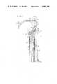
- FIG. 1is a sectional view of the main structure of an embodiment of a bill discriminating apparatus according to the invention
- FIG. 2is a perspective view of the driving mechanism of the apparatus
- FIG. 3is a side elevational view of a reverse roller employed in the driving mechanism
- FIG. 4is a sectional view of a bill storing device with stacked bills.
- FIG. 5is a sectional view of the bill storing device in the state of a bill being returned.
- FIG. 1is a sectional view of a bill discriminating apparatus in the state of a bill being inserted.
- a bill 1is to be inserted through a slot and housed in a bill storing device 2.
- Bills 3 previously inserted by other usersare stacked in a neat stack.
- the bill 1 inserted through a slot 4is judged for authenticity by a judging device while being conveyed in the passage 5 of an apparatus body by a conveying device, and if it is recognized as a false bill, it is immediately sent back to the slot 4, while if it is recognized as a real bill, it is housed in the bill storing device 2.
- a sliding plate 13next starts linear reciprocating motions by rotation of a motor of the bill storing device 2.
- the sliding plate 13is moved to the position 13' and is restored to its original position 13, whereby the bill 1 positioned between a guide plate 14 and the sliding plate 13 is moved to a position between the sliding plate 13 and a compression plate 15, the bill housing operation thus being completed.
- the reference numeral 16denotes a lever, one end of which is attached to the back surface of the compression plate 15, and which is urged by a spring 17 in the direction in which the compression plate 15 presses the bills 3.
- the conveyor belts 18 of the conveying deviceare disposed along the passage 5 in a manner as to intermesh with rollers 7 and 11, whereby rotation of the roller 7 drives the conveyor belts 18, the drive of which rotates the rollers 11.
- Extracting rollers 12are connected to the rollers 11 by belts 19, whereby the extracting rollers 12 rotate in the same direction as the rollers 11 together with the rotation of the rollers 11.
- the outer peripheral surfaces of the rollers 8 and 9are in contact with the belts 18, the outer peripheral surfaces of the rollers 9 being in contact with the outer peripheral surfaces of the reverse rollers 10, and the conveying transmission force of the conveying belts 18 being transmitted to the reverse rollers 10 through the rollers 9.
- the respective rotating directionsare indicated by the arrows in FIG. 2.
- the rollers 9 and the reverse rollers 10are urged by a spring 20 such as to be constantly in contact with each other and at the same time biased toward the conveyor belts 18 by a compression spring 21.
- the reverse roller 10is composed of a middle portion 10A which is in contact with the conveyor belt 18 and which is formed of a resin having a low friction coefficient, and rubber rollers 10B, 10B which are attached to both sides of the middle portion 10A.
- FIG. 4is a sectional view of the apparatus with the bill 1 stored therein and shows the state in which a user is purchasing an article or waiting for the bill 1 to be returned. If an article has been purchased, the apparatus is ready to receive a bill from the next user, while if the return lever is pushed down, the relevant number of bills received from the user are returned, and, further, if a large denomination note is used and change in bills is necessary, the appropriate number of bills is returned.
- FIG. 5is a sectional view of the apparatus in the state of a bill being returned.
- the reference numeral 1denotes the bill to be returned and 3 the remaining bills stored.
- the extracting rollers 12 of the bill storing device 2are first rotated in the arrowed direction, whereby the bill 1, which is pressed from the rear by the compression plate 15, comes into contact with the extracting rollers 12, is drawn up in the arrowed direction (in the direction of the entrance 6) and is lifted up to the passage 5 of the apparatus body.
- the lifted bill 1is clamped by the conveyor belts 18 along the passage 5 and the rollers 8 and is conveyed to the slot, whereby the returning operation is finished.
- the apparatus according to the inventionis provided in the entrance of the bill storing device 2 with the reversing rollers 10 which rotate reversely in relation to the relevant bill conveying direction, so that all the bills except the bill 1 are stopped in order to ensure that only one bill is returned.
- the conveying belts 18are rotating in the bill conveying direction, and the rollers 9, which are in contact with the conveying belts 18, are subjected to the rotation transmission of the conveyor belts 18 and rotate in the direction indicated by the arrow in FIG. 5, thereby conveying the bill 1 to the slot.
- the rotating force acting in the opposite direction relative to the rotation of the rollers 9, i.e. opposite to the bill conveying directionis applied to the reversing rollers 10, which are in contact with the rollers 9 through the spring 20, and rotates the reversing rollers 10.
- This reverse rotation of the reversing rollers 10stops all the bills drawn up from the bill storing device 2 except the bill 1, whereby only the first bill to be returned is safely returned.
- the reversing roller 10which rotates reversely with respect to the relevant bill conveying direction has a sandwich structure, in other words it is composed of a middle portion 10A formed of a resin and rubber rollers 10B attached to both sides of the middle portion 10A, such that the resin middle portion 10A is in contact with the conveyor belt 18 so as to reduce the frictional force produced when they rotate reversely to each other.
- a sandwich structurein other words it is composed of a middle portion 10A formed of a resin and rubber rollers 10B attached to both sides of the middle portion 10A, such that the resin middle portion 10A is in contact with the conveyor belt 18 so as to reduce the frictional force produced when they rotate reversely to each other.
- an apparatus for discriminating billsis provided with reversing rollers which rotate reversely in relation to the relevant bill conveying direction at a position opposite to a conveying device in the vicinity of a bill storing device. Operation of these reversing rollers enables the apparatus to safely pay out only one bill at a time by means of the conveying device when that bill has been extracted for returning from the bill storing device and even when a plurality of bills happen to be erroneously extracted.
Landscapes
- Engineering & Computer Science (AREA)
- Mechanical Engineering (AREA)
- Delivering By Means Of Belts And Rollers (AREA)
Abstract
Description
Claims (6)
Applications Claiming Priority (4)
| Application Number | Priority Date | Filing Date | Title |
|---|---|---|---|
| JP58188522AJPS6081692A (en) | 1983-10-11 | 1983-10-11 | Banknote recognition device refund dispensing device |
| JP58188523AJPS6081693A (en) | 1983-10-11 | 1983-10-11 | Repayment dispenser for paper money identifier |
| JP58-188522 | 1983-10-11 | ||
| JP58-188523 | 1983-10-11 |
Publications (1)
| Publication Number | Publication Date |
|---|---|
| US4682768Atrue US4682768A (en) | 1987-07-28 |
Family
ID=26504985
Family Applications (1)
| Application Number | Title | Priority Date | Filing Date |
|---|---|---|---|
| US06/744,488Expired - LifetimeUS4682768A (en) | 1983-10-11 | 1984-10-05 | Bill receiving/dispensing apparatus |
Country Status (2)
| Country | Link |
|---|---|
| US (1) | US4682768A (en) |
| WO (1) | WO1985001820A1 (en) |
Cited By (13)
| Publication number | Priority date | Publication date | Assignee | Title |
|---|---|---|---|---|
| US4775824A (en)* | 1986-10-08 | 1988-10-04 | Mars, Incorporated | Motor control for banknote handing apparatus |
| US4784274A (en)* | 1983-10-03 | 1988-11-15 | Kabushiki Kaisha Nippon Coinco | Bill device |
| US4818871A (en)* | 1986-05-30 | 1989-04-04 | Commissariat A L'energie Atomique | Process for the detection of superimposed sheets, apparatus for performing the process and application to bank notes |
| EP0405964A3 (en)* | 1989-06-30 | 1991-07-24 | Ncr Corporation | Apparatus for stacking articles in a container |
| US5286017A (en)* | 1993-03-15 | 1994-02-15 | Electrocom Gard Ltd. | Bill escrow/return device |
| US5288066A (en)* | 1992-04-10 | 1994-02-22 | Ncr Corporation | Apparatus and method for loading sheets into a receptacle |
| US5348282A (en)* | 1993-10-04 | 1994-09-20 | Xerox Corporation | Self adjusting feed roll |
| US5451038A (en)* | 1993-02-16 | 1995-09-19 | De La Rue Inter-Innovation Ab | Sheet stacking apparatus |
| US5669601A (en)* | 1996-05-31 | 1997-09-23 | Eastman Kodak Company | Sheet feeding device with floating guide |
| US6193392B1 (en) | 1999-05-27 | 2001-02-27 | Pervaiz Lodhie | Led array with a multi-directional, multi-functional light reflector |
| US20040056414A1 (en)* | 2001-01-15 | 2004-03-25 | Richard Duesterhus | Device for the delivery or receipt of individual sheets |
| US20060151935A1 (en)* | 2002-03-12 | 2006-07-13 | Evolis Card Printer Sa | Device for surface treatment of objects with reduced size and improved ergonomics |
| US20080006509A1 (en)* | 2006-06-28 | 2008-01-10 | Siemens Aktiengesellschaft | Storage module for flat postal items with last-in/first-out operation |
Families Citing this family (1)
| Publication number | Priority date | Publication date | Assignee | Title |
|---|---|---|---|---|
| US4722519A (en)* | 1986-09-05 | 1988-02-02 | Mars, Inc. | Stacker apparatus |
Citations (15)
| Publication number | Priority date | Publication date | Assignee | Title |
|---|---|---|---|---|
| US3123082A (en)* | 1964-03-03 | Gsgt z x | ||
| US3656615A (en)* | 1970-10-09 | 1972-04-18 | Vendo Co | Receiving and transporting apparatus for currency |
| US3773317A (en)* | 1972-02-28 | 1973-11-20 | Licentia Gmbh | Upright conveying device for flat items |
| JPS5046397A (en)* | 1973-08-30 | 1975-04-25 | ||
| JPS5177298A (en)* | 1974-08-29 | 1976-07-05 | Intaa Inobeishon Ab | |
| US4053152A (en)* | 1975-10-16 | 1977-10-11 | Rank Xerox, Ltd. | Sheet feeding device |
| JPS5472855A (en)* | 1977-11-22 | 1979-06-11 | Ikegami Tsushinki Kk | Separation feeder for sheettshaped member |
| JPS55143678A (en)* | 1979-04-25 | 1980-11-10 | Oki Electric Ind Co Ltd | Payment-receipt processor |
| US4239203A (en)* | 1976-12-10 | 1980-12-16 | Laurel Bank Machine Co., Ltd. | Paper delivery roller system |
| JPS5663664A (en)* | 1979-10-29 | 1981-05-30 | Nec Corp | Automatic paper money paying and depositing equipment |
| JPS5678760A (en)* | 1979-11-29 | 1981-06-27 | Fujitsu Ltd | Handling device paper leaf |
| JPS5767452A (en)* | 1980-10-13 | 1982-04-24 | Fuji Electric Co Ltd | Receiving device paper sheet |
| JPS57146396A (en)* | 1981-03-03 | 1982-09-09 | Omron Tateisi Electronics Co | Circulation type money paying/receiving apparatus |
| JPS57189943A (en)* | 1981-05-13 | 1982-11-22 | Hitachi Ltd | Paper sheet feeder |
| US4540081A (en)* | 1982-07-20 | 1985-09-10 | Kabushiki Kaisha Nippon Coinco | Bill accepting device and method for controlling accepting of bills |
- 1984
- 1984-10-05WOPCT/JP1984/000473patent/WO1985001820A1/ennot_activeCeased
- 1984-10-05USUS06/744,488patent/US4682768A/ennot_activeExpired - Lifetime
Patent Citations (15)
| Publication number | Priority date | Publication date | Assignee | Title |
|---|---|---|---|---|
| US3123082A (en)* | 1964-03-03 | Gsgt z x | ||
| US3656615A (en)* | 1970-10-09 | 1972-04-18 | Vendo Co | Receiving and transporting apparatus for currency |
| US3773317A (en)* | 1972-02-28 | 1973-11-20 | Licentia Gmbh | Upright conveying device for flat items |
| JPS5046397A (en)* | 1973-08-30 | 1975-04-25 | ||
| JPS5177298A (en)* | 1974-08-29 | 1976-07-05 | Intaa Inobeishon Ab | |
| US4053152A (en)* | 1975-10-16 | 1977-10-11 | Rank Xerox, Ltd. | Sheet feeding device |
| US4239203A (en)* | 1976-12-10 | 1980-12-16 | Laurel Bank Machine Co., Ltd. | Paper delivery roller system |
| JPS5472855A (en)* | 1977-11-22 | 1979-06-11 | Ikegami Tsushinki Kk | Separation feeder for sheettshaped member |
| JPS55143678A (en)* | 1979-04-25 | 1980-11-10 | Oki Electric Ind Co Ltd | Payment-receipt processor |
| JPS5663664A (en)* | 1979-10-29 | 1981-05-30 | Nec Corp | Automatic paper money paying and depositing equipment |
| JPS5678760A (en)* | 1979-11-29 | 1981-06-27 | Fujitsu Ltd | Handling device paper leaf |
| JPS5767452A (en)* | 1980-10-13 | 1982-04-24 | Fuji Electric Co Ltd | Receiving device paper sheet |
| JPS57146396A (en)* | 1981-03-03 | 1982-09-09 | Omron Tateisi Electronics Co | Circulation type money paying/receiving apparatus |
| JPS57189943A (en)* | 1981-05-13 | 1982-11-22 | Hitachi Ltd | Paper sheet feeder |
| US4540081A (en)* | 1982-07-20 | 1985-09-10 | Kabushiki Kaisha Nippon Coinco | Bill accepting device and method for controlling accepting of bills |
Cited By (18)
| Publication number | Priority date | Publication date | Assignee | Title |
|---|---|---|---|---|
| US4784274A (en)* | 1983-10-03 | 1988-11-15 | Kabushiki Kaisha Nippon Coinco | Bill device |
| US4818871A (en)* | 1986-05-30 | 1989-04-04 | Commissariat A L'energie Atomique | Process for the detection of superimposed sheets, apparatus for performing the process and application to bank notes |
| AU596246B2 (en)* | 1986-10-08 | 1990-04-26 | Mars, Incorporated | Improved motor control for banknote handling apparatus |
| US4775824A (en)* | 1986-10-08 | 1988-10-04 | Mars, Incorporated | Motor control for banknote handing apparatus |
| EP0405964A3 (en)* | 1989-06-30 | 1991-07-24 | Ncr Corporation | Apparatus for stacking articles in a container |
| US5288066A (en)* | 1992-04-10 | 1994-02-22 | Ncr Corporation | Apparatus and method for loading sheets into a receptacle |
| US5451038A (en)* | 1993-02-16 | 1995-09-19 | De La Rue Inter-Innovation Ab | Sheet stacking apparatus |
| US5286017A (en)* | 1993-03-15 | 1994-02-15 | Electrocom Gard Ltd. | Bill escrow/return device |
| US5348282A (en)* | 1993-10-04 | 1994-09-20 | Xerox Corporation | Self adjusting feed roll |
| US5669601A (en)* | 1996-05-31 | 1997-09-23 | Eastman Kodak Company | Sheet feeding device with floating guide |
| US6193392B1 (en) | 1999-05-27 | 2001-02-27 | Pervaiz Lodhie | Led array with a multi-directional, multi-functional light reflector |
| US20040056414A1 (en)* | 2001-01-15 | 2004-03-25 | Richard Duesterhus | Device for the delivery or receipt of individual sheets |
| US7159861B2 (en)* | 2001-01-15 | 2007-01-09 | Wincor Nixdorf International Gmbh | Device for the delivery or receipt of individual sheets |
| US20060151935A1 (en)* | 2002-03-12 | 2006-07-13 | Evolis Card Printer Sa | Device for surface treatment of objects with reduced size and improved ergonomics |
| US7621520B2 (en)* | 2002-03-12 | 2009-11-24 | Evolis Card Printer, SA | Device for surface treatment of objects with reduced size and improved ergonomics |
| US20080006509A1 (en)* | 2006-06-28 | 2008-01-10 | Siemens Aktiengesellschaft | Storage module for flat postal items with last-in/first-out operation |
| EP1872865A3 (en)* | 2006-06-28 | 2008-02-13 | Siemens Aktiengesellschaft | Stacker module for flat postal items operating last-in/first-out |
| US7845484B2 (en)* | 2006-06-28 | 2010-12-07 | Siemens Aktiengesellschaft | Storage module for flat postal items with last-in/first-out operation |
Also Published As
| Publication number | Publication date |
|---|---|
| WO1985001820A1 (en) | 1985-04-25 |
Similar Documents
| Publication | Publication Date | Title |
|---|---|---|
| US4682768A (en) | Bill receiving/dispensing apparatus | |
| JPS5916094A (en) | Paper money receiver | |
| JPH10241003A (en) | Coin receiving and dispensing device | |
| CN104282075B (en) | Bank note treatment device | |
| US6715671B2 (en) | Automatic bill dispensing apparatus with a sorting device | |
| JPS6330672B2 (en) | ||
| JP2929806B2 (en) | Paper sheet separating and feeding device, and automatic cash transaction device using the same | |
| JPH087811B2 (en) | Sensor cleaning device for bill validator | |
| JPS60102341A (en) | Sheet take-out device | |
| JPH0330196B2 (en) | ||
| JPS58225495A (en) | Paper money processor | |
| JPH09227002A (en) | Paper processing equipment | |
| JP3253711B2 (en) | Paper processing equipment | |
| JPH06176244A (en) | Paper sheet processor | |
| WO2018173440A1 (en) | Medium processing apparatus | |
| JPS6151284A (en) | Card fetching/returning mechanism in card processor | |
| JPH0644928Y2 (en) | Banknote storage device | |
| JPH11134469A (en) | Paper counting machine | |
| JP2899509B2 (en) | Card escape mechanism | |
| JPS6081692A (en) | Banknote recognition device refund dispensing device | |
| JPS6262B2 (en) | ||
| JPH0630754Y2 (en) | Banknote storage / return device | |
| JP2513108Y2 (en) | Money transfer device | |
| JPH0325830B2 (en) | ||
| JPS5813402Y2 (en) | Banknote holding/conveying device in vending machines |
Legal Events
| Date | Code | Title | Description |
|---|---|---|---|
| AS | Assignment | Owner name:MATSUSHITA ELECTRIC INDUSTRIAL CO., LTD., 1006, OA Free format text:ASSIGNMENT OF ASSIGNORS INTEREST.;ASSIGNORS:IIDA, KOUJIROU;YOSHIOKA, YASUO;OGAWA, HIROSHI;AND OTHERS;REEL/FRAME:004418/0919 Effective date:19850516 Owner name:MATSUSHITA ELECTRIC INDUSTRIAL CO., LTD., A CORP O Free format text:ASSIGNMENT OF ASSIGNORS INTEREST;ASSIGNORS:IIDA, KOUJIROU;YOSHIOKA, YASUO;OGAWA, HIROSHI;AND OTHERS;REEL/FRAME:004418/0919 Effective date:19850516 | |
| STCF | Information on status: patent grant | Free format text:PATENTED CASE | |
| FEPP | Fee payment procedure | Free format text:PAYOR NUMBER ASSIGNED (ORIGINAL EVENT CODE: ASPN); ENTITY STATUS OF PATENT OWNER: LARGE ENTITY | |
| FPAY | Fee payment | Year of fee payment:4 | |
| FEPP | Fee payment procedure | Free format text:PAYER NUMBER DE-ASSIGNED (ORIGINAL EVENT CODE: RMPN); ENTITY STATUS OF PATENT OWNER: LARGE ENTITY Free format text:PAYOR NUMBER ASSIGNED (ORIGINAL EVENT CODE: ASPN); ENTITY STATUS OF PATENT OWNER: LARGE ENTITY | |
| FPAY | Fee payment | Year of fee payment:8 | |
| FPAY | Fee payment | Year of fee payment:12 | |
| AS | Assignment | Owner name:UTEX INDUSTRIES, INC., TEXAS Free format text:RELEASE OF SECURITY INTEREST IN PATENT COLLATERAL;ASSIGNOR:GENERAL ELECTRIC CAPITAL CORPORATION;REEL/FRAME:025642/0187 Effective date:20101215 Owner name:DURAQUEST, INC., TEXAS Free format text:RELEASE OF SECURITY INTEREST IN PATENT COLLATERAL;ASSIGNOR:GENERAL ELECTRIC CAPITAL CORPORATION;REEL/FRAME:025642/0187 Effective date:20101215 |