US4682589A - Penile prosthesis - Google Patents
Penile prosthesisDownload PDFInfo
- Publication number
- US4682589A US4682589AUS06/810,420US81042085AUS4682589AUS 4682589 AUS4682589 AUS 4682589AUS 81042085 AUS81042085 AUS 81042085AUS 4682589 AUS4682589 AUS 4682589A
- Authority
- US
- United States
- Prior art keywords
- fluid
- reservoir
- piston
- pressure chamber
- implant
- Prior art date
- Legal status (The legal status is an assumption and is not a legal conclusion. Google has not performed a legal analysis and makes no representation as to the accuracy of the status listed.)
- Expired - Lifetime
Links
- 239000012530fluidSubstances0.000claimsabstractdescription53
- 239000007943implantSubstances0.000claimsabstractdescription46
- 210000003899penisAnatomy0.000claimsdescription16
- 210000005226corpus cavernosumAnatomy0.000claimsdescription14
- 230000007246mechanismEffects0.000claimsdescription6
- 239000000463materialSubstances0.000description7
- 238000005452bendingMethods0.000description6
- 230000001856erectile effectEffects0.000description6
- 230000001105regulatory effectEffects0.000description3
- 239000004945silicone rubberSubstances0.000description3
- FAPWRFPIFSIZLT-UHFFFAOYSA-MSodium chlorideChemical compound[Na+].[Cl-]FAPWRFPIFSIZLT-UHFFFAOYSA-M0.000description2
- 201000001881impotenceDiseases0.000description2
- 238000000034methodMethods0.000description2
- 238000005086pumpingMethods0.000description2
- 229920002379silicone rubberPolymers0.000description2
- 239000011780sodium chlorideSubstances0.000description2
- 210000001519tissueAnatomy0.000description2
- 210000003484anatomyAnatomy0.000description1
- 238000004873anchoringMethods0.000description1
- 239000000560biocompatible materialSubstances0.000description1
- 230000001276controlling effectEffects0.000description1
- 238000011443conventional therapyMethods0.000description1
- 238000002513implantationMethods0.000description1
- 230000007794irritationEffects0.000description1
- 210000001699lower legAnatomy0.000description1
- 238000005259measurementMethods0.000description1
- 229920002529medical grade siliconePolymers0.000description1
- 239000012528membraneSubstances0.000description1
- 231100000252nontoxicToxicity0.000description1
- 230000003000nontoxic effectEffects0.000description1
- 229920001296polysiloxanePolymers0.000description1
- 229920002635polyurethanePolymers0.000description1
- 239000004814polyurethaneSubstances0.000description1
- 230000000284resting effectEffects0.000description1
- 230000000717retained effectEffects0.000description1
- 239000013464silicone adhesiveSubstances0.000description1
- 229910001220stainless steelInorganic materials0.000description1
- 239000010935stainless steelSubstances0.000description1
- 238000001356surgical procedureMethods0.000description1
- XLYOFNOQVPJJNP-UHFFFAOYSA-NwaterSubstancesOXLYOFNOQVPJJNP-UHFFFAOYSA-N0.000description1
Images

Classifications
- A—HUMAN NECESSITIES
- A61—MEDICAL OR VETERINARY SCIENCE; HYGIENE
- A61F—FILTERS IMPLANTABLE INTO BLOOD VESSELS; PROSTHESES; DEVICES PROVIDING PATENCY TO, OR PREVENTING COLLAPSING OF, TUBULAR STRUCTURES OF THE BODY, e.g. STENTS; ORTHOPAEDIC, NURSING OR CONTRACEPTIVE DEVICES; FOMENTATION; TREATMENT OR PROTECTION OF EYES OR EARS; BANDAGES, DRESSINGS OR ABSORBENT PADS; FIRST-AID KITS
- A61F2/00—Filters implantable into blood vessels; Prostheses, i.e. artificial substitutes or replacements for parts of the body; Appliances for connecting them with the body; Devices providing patency to, or preventing collapsing of, tubular structures of the body, e.g. stents
- A61F2/02—Prostheses implantable into the body
- A61F2/26—Penis implants
Definitions
- the present inventionrelates to a penile prosthesis. More particularly, it relates to an inflatable penile prosthesis which is adapted to be implanted in man for treatment of erectile impotence.
- penile prostheseshave been employed in the past.
- One type of penile prosthesisis a pair of rods of suitable stiffness which are surgically implanted into the corpus cavernosum of the penis.
- One disadvantage of some of the rod-type implantsis the permanent stiffness of the rod which can be a source of physical pain and/or embarrassment to the patient.
- the prostheses disclosed in U.S. Pat. Nos. 3,893,476 and 4,066,037are representatives of the rod type prostheses.
- the inflatable prosthesisof U.S. Pat. No. 3,954,102.
- the patented prosthesisincludes two fairly long inflatable and distensible tubes that are surgically implanted in the corpus cavernosum of the penis. Each of the two tubes is connected by tubing to a pressure bulb of inflating fluid which is implanted elsewhere in the body. Because of the volume required to inflate, distend, pressurize and rigidize the inflatable tubes, the pressure bulbs are relatively large.
- penile implantswhich are essentially cylinders which contain a hydraulic system comprising a pressure chamber, a reservoir and a pump for transferring fluid from the reservoir to the pressure chamber.
- the pumpmust be manually squeezed to transfer the fluid to the pressure chamber.
- Representative of such implantsare those of U.S. Pat. Nos. 4,353,360, 4,267,829 and 4,383,525.
- the penile prosthesis of the present inventioncomprises a pair of penile implants.
- Each of the implantsis an elongated cylindrical member which is adapted to be implanted into the corpus cavernosum.
- the cylinderincludes a proximal portion for implanting in the root end of the corpus and an elongated flexible, hollow distal portion having a non-distensible pressure chamber and a conical tip which is adapted to be implanted in the corpus cavernosum of the pendulus penis.
- the cylinderalso includes an internal reservoir for fluid to fill and pressurize the pressure chamber to make the non-distensible distal portion rigid and to stiffen the penis and means for automatically transferring fluid from the reservoir to the pressure chamber without pumping.
- the means for transferring fluid to the pressure chamberis a gas filled bladder which is maintained in a compressed or non-expanded state in the reservoir by the fluid pressure in the reservoir which is higher than the fluid pressure in the pressure chamber.
- the means for transferring fluidis a spring driven piston located in the reservoir.
- the springis normally compressed by the fluid pressure in the reservoir which is higher than that in the pressure chamber.
- a valveis opened to relieve the pressure in the reservoir the spring is released and it expands to cause the piston to transfer fluid from the reservoir under pressure into the pressure chamber.
- the springis normally held compressed by a ball point pen type latch-unlatch mechanism which is both latched and released by moving the piston back.
- the proximal portion of implant of the present inventionis preferably an anchoring stem which is relatively stiff so that it can be implanted into the root end of the corpus cavernosum to support the implant.
- the remainder of the implantis of a less stiff and softer material which reduces the risk of tissue irritation.
- the cylinderWhen not pressurized the cylinder is flexible and permits the pendulus penis to assume a normal flaccid position.
- the tip at the distal end of the implantis soft and paraboloidal to fit the end of the corpus cavernosum, and to enhance the physiological compatibility of the implant.
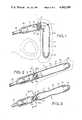
- FIG. 1is a side view, partly in section, of a preferred embodiment of the penile implant of the present invention with a gas filled bladder in the reservoir.
- One of the two identical penile implantsis shown surgically implanted in a male and in a non-pressurized condition;
- FIG. 2is a side view similar to FIG. 1, except that the implant is pressurized;
- FIG. 3is a side view similar to FIG. 2, showing the pressure chamber being depressurized
- FIG. 4is an enlarged sectional view taken along line 4--4 in FIG. 3;
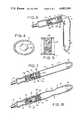
- FIG. 5is a view, in section, of an alternative valve system
- FIG. 6is a side view, partly in section, of a penile implant of the present invention with a spring driven piston in the reservoir;
- FIG. 7is a side view similar to FIG. 5 except that the implant is pressurized
- FIG. 8is a side view similar to FIG. 6 showing the pressure chamber being depressurized.
- FIG. 9is a side view, partly in section, of another penile implant of the present invention with a spring driven piston
- FIG. 10is a side view similar to FIG. 8 with the implant pressurized.
- FIG. 11is a side view similar to FIG. 8 showing the pressure chamber being depressurized.
- the preferred penile erectile systemwhich is shown in FIGS. 1-4, comprises a pair of cylindrical penile implants which are to be implanted in the corpora cavernosa of the penis.
- the two implantsare identical, therefore, only one will be described in detail.
- the implant 11is a generally cylindrical member with a short proximal stem 12 and a longer distal portion 13 including a fluid reservoir 14, a pressure chamber 15 and a conical distal tip 16.
- the stem 12which is of a relatively stiff material is implanted in the root end of a corpus cavernosum.
- the reservoir 14 of the distal portion 13is implanted in the corpus near the base adjacent the stem 12 and the pressure chamber 15 and the tip 16 are implanted in the portion of the corpus in the pendulous penis.
- Each of the two implantsis postioned in a separate corpus cavernosum of the penis.
- the pressure chamber 15 of the implant 11has a wall 17 of a flexible, non-distensible material so that the chamber 15 does not expand significantly in volume when pressurized but instead becomes stiff and rigid.
- the wall 17is preferably of a material such as reinforced silicone rubber or polyurethane which either does not stretch or stretches only a given amount.
- the wall 18 of the reservoir 14also is non-distensible, and it is preferably thicker to contain the fluid pressure and stiffer and less flexible than the wall 17. The necessary fluid tight seals between the walls 17, 18, the stem 12 and tip 16 may be made with a silicone adhesive or by other suitable means.
- the chamber 15When the implant 11 is in a nonpressurized state as seen in FIG. 1, the chamber 15 is substantially filled with a non-compressible hydraulic fluid (not seen) which is biocompatible, such as saline or a free flowing silicone gel.
- a non-compressible hydraulic fluid(not seen) which is biocompatible, such as saline or a free flowing silicone gel.
- the distal portion 13, including chamber 15,flexes and permits the penis to assume a substantially normal, flaccid position.
- FIG. 2it can be seen that when the chamber 15 of implant 11 is pressurized, the distal portion 13 is rigid as the result of the chamber 15 being completely filled with fluid under pressure. The penis then assumes an erectile position.
- the means for transferring fluid to the pressure chamber 15is a gas filled bladder 20 positioned in the reservoir 14.
- the bladder 20is preferably filled with CO 2 gas at about 1000 to 2000 cm H 2 O and preferably more than 1500 cm H 2 O.
- the bladder 20 and its gas contentsare compressed and partially collapsed because the fluid pressure in the reservoir 14.
- the bladder 20is fully expanded and no longer collapsed because the fluid pressure in the reservoir 14 is now less than the gas pressure in the bladder 20.
- the pressurizing fluid in the reservoir 14 in the non-pressurized statehas been transferred to the pressure chamber 15 by opening the valve means 19 and permitting the bladder 20 to expand and force the fluid into the pressure chamber 15.
- the valve means 19controls the fluid flow between the reservoir 14 and the pressure chamber 15.
- the valve means 19includes a deformable valve body 21 which has a passage 22 which leads from the reservoir 14 to the pressure chamber 15.
- a ball 23is located in an enlarged portion 24 of the passage 22 normally preventing the flow of fluid through the passage 22 between reservoir 14 and chamber 15.
- the valve means 19is normally closed, but it can be opened by manipulation from the outside by deforming the valve body 21 to create leak paths 25 in the passage 22 about the ball 23 (seen best in FIG. 4).
- the passage 22is opened by squeezing and deforming the valve body 21 to create the leak paths 25, the pressure on the bladder 20 in reservoir 14 is relieved and fluid is forced out of the reservoir 14 into the pressure chamber 15 by the expansion of the bladder 20.
- the pressure of the gas in the bladder 20causes it to expand to its full size which results in sufficient fluid being transferred to completely fill the pressure chamber 15 and make it rigid.
- the pressure chamber 15is depressurized by either simultaneously bending or squeezing the distal portion 13 and deforming the valve body 21 to create leak paths 25 about the ball 23 thus permitting fluid to return to the reservoir 14.
- the squeezing of the pressure chamber 15causes the fluid pressure in the pressure chamber to rise and the pressurizing fluid to flow under pressure from the pressure chamber 15 back into the reservoir 14.
- the resulting increased fluid pressure in the reservoir 14causes the gas filled bladder 20 to once again to contract or collapse.
- the wall 18 of the reservoir 14must be strong enough to withstand the fluid pressures required to function and the wall 17 of the pressure chamber 15 must be sufficiently non-distensible to provide rigidity sufficient to support an erection when the chamber 15 is pressurized.
- the exact dimensions and materials of the wallsare not critical so long as the walls possess the properties required to provide their desired functions.
- FIG. 5an alternative valve system is shown that consists of a ball valve similar to that of FIGS. 1 and 4 and a pressure regulating valve similar to that of my earlier U.S. Pat. No. 4,364,379, which is incorporated by reference herein.
- the pressure regulating valveis set to open at pressures higher than those generated in the pressure chamber during intercourse.
- the pressure chamberis pressurized by manipulating the ball valve open and is depressurized by bending the pressure chamber to generate a high enough pressure to open the pressure regulating valve.
- the valve systemmakes it unnecessary to manipulate the valve to affect depressurization; bending the pressure chamber is sufficient to generate valve opening pressures.
- FIGS. 6 to 8another embodiment of the implant of the present invention is seen.
- the stem 12, distal portion 13, and tip 16are similar to those of the embodiment of FIGS. 1 to 4.
- the fluid transferring meansis a spring driven piston 26.
- the piston 26is normally retained in the compressed state seen in FIG. 6 by the fluid pressure in the reservoir 14 which is sensed by the face 27 of the piston 26.
- the fluid in reservoir 14is relieved or falls below the force required to compress the spring 28
- the fluid in reservoir 14, which is in front of the piston face 27is forceably driven under pressure into the pressure chamber 15 by the movement of the piston as a result of the expansion of the spring 28.
- FIG. 6the implant is shown in its normal flaccid state and in FIG. 7 it is shown pressurized and rigid.
- FIG. 8the implant is shown being depressurized by forces being simultaneously exerted on the pressure chamber 15 to reduce its volume and on the valve 28 to deform and open it to fluid flow. As the fluid flows back into the area of the reservoir 14 adjacent the stem 12 the walls of that area resume the non-depressed state seen in FIG. 6.
- the valve 29 shown in the embodiments of FIGS. 6 to 8has a deformable valve body 30 with a passage 31 closed at each end by deformable membranes 32, 33.
- the ball valve of the embodiment of FIGS. 1 to 4can also be used. The only requirements of the valve are that it is normally closed and that it can be opened from the outside by manipulation.
- FIGS. 9 to 11another embodiment of an implant having a spring driven piston is shown.
- the embodimentis similar to that of FIGS. 6 to 8, but there is no valve means.
- the implant 11has a piston 34 having a piston head 35 mounted within the reservoir 14.
- the piston head 35has a front piston face 36 and a resilient piston ring 37 forms a fluid tight seal with the wall of the reservoir 14.
- the fluid tight seal provided by the piston ring 37permits the areas on opposite sides of the piston head 35 to be maintained at separate and different fluid pressures.
- a piston rod 38extends from the back of the piston head 35 to a ball point pen type latch and unlatch mechanism generally referred to as 39.
- the latch and unlatch mechanism 39can be a relatively simple one such as those used in ball point pens and the like. Suitable mechanisms are described in U.S. Pat. Nos. 3,237,604 and 3,810,201 which are incorporated by reference herein.
- the implant of FIGS. 9 to 11may be pressurized by exerting pressure on the piston face 37 by bending or squeezing the pressure cylinder 15 as seen in FIG. 9.
- the latch mechanismis disengaged and the piston 34 is driven forward by the spring 40 transferring the fluid in the reservoir before the piston face 36 into the pressure chamber 15 causing it to become rigid as seen in FIG. 10.
- the pressure chamber 15can be depressurized by either squeezing or bending the pressure chamber 15 as seen in FIG. 11, to raise the fluid pressure in chamber 15 and to thus overcome the force of the spring 40 to force the piston 34 back into the latched position.
- All the components of the described implantsare preferably made of biocompatible materials having the necessary properties to function as intended.
- substantially filledas used herein to describe the fluid content of a chamber in the penile implant means that a chamber contains about 60% to about 95% or more of its capacity of a non-compressible fluid such as water, saline or a free flowing gel.
- a non-compressible fluidsuch as water, saline or a free flowing gel.
- the actual content of fluidcan vary; however, the implant when "substantially filled” should be still sufficiently flexible so that the penis can assume a normal flaccid position.
- non-distensibleas used herein is intended to cover materials or components which do not distend or distend to only a limited extent which still permits the device to function as intended.
- All the parts and components of the prosthesis, except for the springs which may be of stainless steel,are preferably made of or covered with medical grade silicone rubber which is non-reactive, non-toxic and well tolerated by the adjacent organic tissues. Silicone rubber is preferred because it is quite resistant to wear and remains functional for long period of time. However, other suitable materials possessing desirable properties may also be employed.
- the preferred method of implantation of the erectile systems of FIGS. 1 to 11is through an incision made in the penis. After appropriate incision, each corpus cavernosum is dilated distally and proximally to accept the implants. The appropriate anatomical measurements are made to insure that the proximal end of the implant or implants will be positioned is the proximal crus. An appropriately sized implant is then inserted into the corpus cavernosum of the penis. The distal tip is positioned in the glans end of the corpus cavernosum. The stem at the proximal end of the implant is anchored in the root end of the corpus cavernosum.
- the identical procedureis performed on the other side of the penis to complete the surgical procedure.
- the stems of the two implantspreferably will diverge laterally to accommodate the anatomy, to provide lateral stability to the penis and to help prevent rotation of the implants.
- the incisionis then closed.
Landscapes
- Health & Medical Sciences (AREA)
- Reproductive Health (AREA)
- Cardiology (AREA)
- Oral & Maxillofacial Surgery (AREA)
- Transplantation (AREA)
- Engineering & Computer Science (AREA)
- Biomedical Technology (AREA)
- Heart & Thoracic Surgery (AREA)
- Vascular Medicine (AREA)
- Life Sciences & Earth Sciences (AREA)
- Animal Behavior & Ethology (AREA)
- General Health & Medical Sciences (AREA)
- Public Health (AREA)
- Veterinary Medicine (AREA)
- Prostheses (AREA)
Abstract
Description
Claims (2)
Priority Applications (1)
| Application Number | Priority Date | Filing Date | Title |
|---|---|---|---|
| US06/810,420US4682589A (en) | 1980-05-15 | 1985-12-18 | Penile prosthesis |
Applications Claiming Priority (3)
| Application Number | Priority Date | Filing Date | Title |
|---|---|---|---|
| US06/150,231US4318396A (en) | 1980-05-15 | 1980-05-15 | Penile prosthesis |
| US06/680,746US4622958A (en) | 1984-12-12 | 1984-12-12 | Penile implant with accumulator |
| US06/810,420US4682589A (en) | 1980-05-15 | 1985-12-18 | Penile prosthesis |
Related Parent Applications (1)
| Application Number | Title | Priority Date | Filing Date |
|---|---|---|---|
| US06/459,776Continuation-In-PartUS4791917A (en) | 1981-10-22 | 1983-01-21 | Penile prosthesis |
Publications (1)
| Publication Number | Publication Date |
|---|---|
| US4682589Atrue US4682589A (en) | 1987-07-28 |
Family
ID=27386936
Family Applications (1)
| Application Number | Title | Priority Date | Filing Date |
|---|---|---|---|
| US06/810,420Expired - LifetimeUS4682589A (en) | 1980-05-15 | 1985-12-18 | Penile prosthesis |
Country Status (1)
| Country | Link |
|---|---|
| US (1) | US4682589A (en) |
Cited By (23)
| Publication number | Priority date | Publication date | Assignee | Title |
|---|---|---|---|---|
| US4852555A (en)* | 1987-12-02 | 1989-08-01 | Medical Engineering Corporation | Inflatable penile prosthesis |
| US4917110A (en)* | 1986-07-17 | 1990-04-17 | Medical Engineering Corporation | Penile prosthesis |
| US4995380A (en)* | 1989-11-07 | 1991-02-26 | Medical Engineering Corporation | Penile prosthesis |
| US5010882A (en)* | 1989-11-13 | 1991-04-30 | American Medical Systems, Inc. | Implantable penile prosthesis |
| US20090084447A1 (en)* | 2000-12-27 | 2009-04-02 | Ams Research Corporation | Diaphragm Based Spontaneous Inflation Inhibitor in a Pump for an Inflatable Prosthesis |
| US20090105818A1 (en)* | 2007-10-23 | 2009-04-23 | Ams Research Corporation | Malleable Prosthesis with Enhanced Concealability |
| US20090105530A1 (en)* | 2007-10-23 | 2009-04-23 | Ams Research Corporation | Corrugated Inflatable Penile Prosthesis Cylinder |
| US20090287042A1 (en)* | 2000-12-27 | 2009-11-19 | Ams Research Corporation | Penile Pump with Side Release Mechanism |
| US7946975B2 (en) | 2005-04-08 | 2011-05-24 | Ams Research Corporation | Fluid reservoir for penile implant devices |
| US20110190577A1 (en)* | 2010-02-03 | 2011-08-04 | Coloplast A/S | Inflatable penile implant |
| US20110190576A1 (en)* | 2010-02-04 | 2011-08-04 | Coloplast A/S | Inflatable penile implant |
| US20110201880A1 (en)* | 2010-02-12 | 2011-08-18 | Fogarty Terence M | Inflatable penile prosthesis with spool valve |
| US8109870B2 (en) | 2006-11-10 | 2012-02-07 | Ams Research Corporation | Inflatable penile prosthesis bypass valve noise reduction |
| US8123674B2 (en) | 2007-11-12 | 2012-02-28 | Ams Research Corporation | Corrugated expansion-constraining sleeve for an inflatable penile prosthesis cylinder |
| US9084678B2 (en) | 2012-01-20 | 2015-07-21 | Ams Research Corporation | Automated implantable penile prosthesis pump system |
| WO2015134838A1 (en)* | 2014-03-07 | 2015-09-11 | Ams Research Corporation | Implantable penile prosthesis cylinder and pressurization system |
| US20160081802A1 (en)* | 2014-09-24 | 2016-03-24 | Ams Research, Llc | Implantable penile prosthesis inflation apparatus |
| US9474610B2 (en) | 2010-12-21 | 2016-10-25 | Boston Scientific Scimed, Inc. | Adjustable length rear tip extender for penile prosthesis |
| EP2967871A4 (en)* | 2013-03-14 | 2016-12-21 | Univ Texas | IMPLANTABLE MEDICAL APPARATUS AND SYSTEMS |
| US9554937B2 (en) | 2014-06-16 | 2017-01-31 | Coloplast A/S | Penile prosthetic pump having an inlet valve with a lockout flange |
| US9649217B2 (en) | 2014-07-08 | 2017-05-16 | Coloplast A/S | Implantable penile prosthetic lockout valve assembly |
| US9987136B2 (en) | 2016-09-09 | 2018-06-05 | Coloplast A/S | Penile prosthetic pump with an inflation assembly including a rotary valve |
| EP4039230A1 (en)* | 2021-02-09 | 2022-08-10 | Coloplast A/S | A pump having a volume amplification mechanism for an inflatable penile prosthesis |
Citations (16)
| Publication number | Priority date | Publication date | Assignee | Title |
|---|---|---|---|---|
| US3853122A (en)* | 1973-10-12 | 1974-12-10 | B Strauch | Method and device for achieving a penile erection |
| US3954102A (en)* | 1974-07-19 | 1976-05-04 | American Medical Systems, Inc. | Penile erection system and methods of implanting and using same |
| US4009711A (en)* | 1976-03-17 | 1977-03-01 | Uson Aurelio C | Penile prosthesis for the management of erectile impotence |
| US4201202A (en)* | 1978-09-25 | 1980-05-06 | Medical Engineering Corp. | Penile implant |
| US4267829A (en)* | 1979-04-11 | 1981-05-19 | American Medical Systems, Inc. | Penile prosthesis |
| US4318396A (en)* | 1980-05-15 | 1982-03-09 | Medical Engineering Corporation | Penile prosthesis |
| US4342308A (en)* | 1980-10-02 | 1982-08-03 | Medical Engineering Corporation | Penile erectile system |
| US4353360A (en)* | 1980-10-31 | 1982-10-12 | Medical Engineering Corporation | Penile erectile system |
| US4360010A (en)* | 1980-05-15 | 1982-11-23 | Medical Engineering Corporation | Penile prosthesis |
| US4364379A (en)* | 1980-05-15 | 1982-12-21 | Finney Roy P | Penile erectile system |
| US4399812A (en)* | 1981-12-31 | 1983-08-23 | Whitehead Edgar D | Penile prosthetic device |
| US4399811A (en)* | 1981-08-04 | 1983-08-23 | Medical Engineering Corporation | Implantable penile erectile system |
| US4550720A (en)* | 1983-11-15 | 1985-11-05 | Medical Engineering Corporation | Capacitance device for medical implant |
| US4572168A (en)* | 1983-12-20 | 1986-02-25 | Fischell Robert | Fully implantable vapor pressure actuated penile erection device and method |
| US4594997A (en)* | 1984-11-13 | 1986-06-17 | Hakky Said I | Self actuated penile implant |
| US4596242A (en)* | 1983-08-26 | 1986-06-24 | Fischell Robert | Method and apparatus for achieving penile erection in a human male |
- 1985
- 1985-12-18USUS06/810,420patent/US4682589A/ennot_activeExpired - Lifetime
Patent Citations (17)
| Publication number | Priority date | Publication date | Assignee | Title |
|---|---|---|---|---|
| US3853122A (en)* | 1973-10-12 | 1974-12-10 | B Strauch | Method and device for achieving a penile erection |
| US3954102A (en)* | 1974-07-19 | 1976-05-04 | American Medical Systems, Inc. | Penile erection system and methods of implanting and using same |
| US4009711A (en)* | 1976-03-17 | 1977-03-01 | Uson Aurelio C | Penile prosthesis for the management of erectile impotence |
| US4201202A (en)* | 1978-09-25 | 1980-05-06 | Medical Engineering Corp. | Penile implant |
| US4267829A (en)* | 1979-04-11 | 1981-05-19 | American Medical Systems, Inc. | Penile prosthesis |
| US4383525A (en)* | 1979-12-28 | 1983-05-17 | American Medical Systems, Inc. | Implantable penile prosthetic cylinder with inclusive fluid reservoir |
| US4360010A (en)* | 1980-05-15 | 1982-11-23 | Medical Engineering Corporation | Penile prosthesis |
| US4364379A (en)* | 1980-05-15 | 1982-12-21 | Finney Roy P | Penile erectile system |
| US4318396A (en)* | 1980-05-15 | 1982-03-09 | Medical Engineering Corporation | Penile prosthesis |
| US4342308A (en)* | 1980-10-02 | 1982-08-03 | Medical Engineering Corporation | Penile erectile system |
| US4353360A (en)* | 1980-10-31 | 1982-10-12 | Medical Engineering Corporation | Penile erectile system |
| US4399811A (en)* | 1981-08-04 | 1983-08-23 | Medical Engineering Corporation | Implantable penile erectile system |
| US4399812A (en)* | 1981-12-31 | 1983-08-23 | Whitehead Edgar D | Penile prosthetic device |
| US4596242A (en)* | 1983-08-26 | 1986-06-24 | Fischell Robert | Method and apparatus for achieving penile erection in a human male |
| US4550720A (en)* | 1983-11-15 | 1985-11-05 | Medical Engineering Corporation | Capacitance device for medical implant |
| US4572168A (en)* | 1983-12-20 | 1986-02-25 | Fischell Robert | Fully implantable vapor pressure actuated penile erection device and method |
| US4594997A (en)* | 1984-11-13 | 1986-06-17 | Hakky Said I | Self actuated penile implant |
Non-Patent Citations (1)
| Title |
|---|
| Hakky, PCT Application WO 80/00302.* |
Cited By (33)
| Publication number | Priority date | Publication date | Assignee | Title |
|---|---|---|---|---|
| US4917110A (en)* | 1986-07-17 | 1990-04-17 | Medical Engineering Corporation | Penile prosthesis |
| US4852555A (en)* | 1987-12-02 | 1989-08-01 | Medical Engineering Corporation | Inflatable penile prosthesis |
| US4995380A (en)* | 1989-11-07 | 1991-02-26 | Medical Engineering Corporation | Penile prosthesis |
| US5010882A (en)* | 1989-11-13 | 1991-04-30 | American Medical Systems, Inc. | Implantable penile prosthesis |
| US20090084447A1 (en)* | 2000-12-27 | 2009-04-02 | Ams Research Corporation | Diaphragm Based Spontaneous Inflation Inhibitor in a Pump for an Inflatable Prosthesis |
| US8276591B2 (en) | 2000-12-27 | 2012-10-02 | Ams Research Corporation | Diaphragm based spontaneous inflation inhibitor in a pump for an inflatable prosthesis |
| US20090287042A1 (en)* | 2000-12-27 | 2009-11-19 | Ams Research Corporation | Penile Pump with Side Release Mechanism |
| US7946975B2 (en) | 2005-04-08 | 2011-05-24 | Ams Research Corporation | Fluid reservoir for penile implant devices |
| US8109870B2 (en) | 2006-11-10 | 2012-02-07 | Ams Research Corporation | Inflatable penile prosthesis bypass valve noise reduction |
| US9517133B2 (en) | 2007-10-23 | 2016-12-13 | Boston Scientific Scimed, Inc. | Malleable prosthesis with enhanced concealability |
| US8114011B2 (en) | 2007-10-23 | 2012-02-14 | Ams Research Corporation | Corrugated inflatable penile prosthesis cylinder |
| US20090105530A1 (en)* | 2007-10-23 | 2009-04-23 | Ams Research Corporation | Corrugated Inflatable Penile Prosthesis Cylinder |
| US8911350B2 (en) | 2007-10-23 | 2014-12-16 | Ams Research Corporation | Malleable prosthesis with enhanced concealability |
| US20090105818A1 (en)* | 2007-10-23 | 2009-04-23 | Ams Research Corporation | Malleable Prosthesis with Enhanced Concealability |
| US8123674B2 (en) | 2007-11-12 | 2012-02-28 | Ams Research Corporation | Corrugated expansion-constraining sleeve for an inflatable penile prosthesis cylinder |
| US8016746B2 (en) | 2010-02-03 | 2011-09-13 | Coloplast A/S | Inflatable penile implant |
| US20110190577A1 (en)* | 2010-02-03 | 2011-08-04 | Coloplast A/S | Inflatable penile implant |
| US8545393B2 (en) | 2010-02-04 | 2013-10-01 | Coloplast A/S | Inflatable penile implant |
| US20110190576A1 (en)* | 2010-02-04 | 2011-08-04 | Coloplast A/S | Inflatable penile implant |
| US20110201880A1 (en)* | 2010-02-12 | 2011-08-18 | Fogarty Terence M | Inflatable penile prosthesis with spool valve |
| US8241203B2 (en) | 2010-02-12 | 2012-08-14 | Fogarty Terence M | Inflatable penile prosthesis with spool valve |
| US9474610B2 (en) | 2010-12-21 | 2016-10-25 | Boston Scientific Scimed, Inc. | Adjustable length rear tip extender for penile prosthesis |
| US9084678B2 (en) | 2012-01-20 | 2015-07-21 | Ams Research Corporation | Automated implantable penile prosthesis pump system |
| US9808343B2 (en) | 2012-01-20 | 2017-11-07 | Boston Scientific Scimed, Inc. | Automated implantable penile prosthesis pump system |
| EP2967871A4 (en)* | 2013-03-14 | 2016-12-21 | Univ Texas | IMPLANTABLE MEDICAL APPARATUS AND SYSTEMS |
| WO2015134838A1 (en)* | 2014-03-07 | 2015-09-11 | Ams Research Corporation | Implantable penile prosthesis cylinder and pressurization system |
| US9554937B2 (en) | 2014-06-16 | 2017-01-31 | Coloplast A/S | Penile prosthetic pump having an inlet valve with a lockout flange |
| US9649217B2 (en) | 2014-07-08 | 2017-05-16 | Coloplast A/S | Implantable penile prosthetic lockout valve assembly |
| US20160081802A1 (en)* | 2014-09-24 | 2016-03-24 | Ams Research, Llc | Implantable penile prosthesis inflation apparatus |
| US9937045B2 (en)* | 2014-09-24 | 2018-04-10 | Boston Scientific Scimed, Inc. | Implantable penile prosthesis inflation apparatus |
| US9987136B2 (en) | 2016-09-09 | 2018-06-05 | Coloplast A/S | Penile prosthetic pump with an inflation assembly including a rotary valve |
| EP4039230A1 (en)* | 2021-02-09 | 2022-08-10 | Coloplast A/S | A pump having a volume amplification mechanism for an inflatable penile prosthesis |
| US12036124B2 (en) | 2021-02-09 | 2024-07-16 | Coloplast A/S | Pump having a volume amplification mechanism for an inflatable penile prosthesis |
Similar Documents
| Publication | Publication Date | Title |
|---|---|---|
| US4682589A (en) | Penile prosthesis | |
| US4360010A (en) | Penile prosthesis | |
| US4364379A (en) | Penile erectile system | |
| US4353360A (en) | Penile erectile system | |
| US4881530A (en) | Penile prosthesis | |
| US4726360A (en) | Penile prosthesis | |
| US4574792A (en) | Penile erectile system | |
| US4369771A (en) | Penile erectile system | |
| US4773403A (en) | Penile prosthesis | |
| US4342308A (en) | Penile erectile system | |
| US4399811A (en) | Implantable penile erectile system | |
| US4318396A (en) | Penile prosthesis | |
| US4523584A (en) | Penile erectile system | |
| US4201202A (en) | Penile implant | |
| US4550720A (en) | Capacitance device for medical implant | |
| US4602625A (en) | Penile erectile system | |
| US5063914A (en) | Penile prosthesis | |
| US4917110A (en) | Penile prosthesis | |
| US4898158A (en) | Penile implant with improved pressure relief valve | |
| US4823779A (en) | Penile implant with compensator | |
| US5669870A (en) | Penile implant for improved appearance | |
| US4378792A (en) | Penile prosthesis | |
| US4895139A (en) | Inflatable penile prosthesis with bend release valve | |
| US4550719A (en) | Implantable penile erectile system | |
| US4457335A (en) | Penile erectile system |
Legal Events
| Date | Code | Title | Description |
|---|---|---|---|
| AS | Assignment | Owner name:MEDICAL ENGINEERING CORPORATION, RACINE, WI., A CO Free format text:ASSIGNMENT OF ASSIGNORS INTEREST.;ASSIGNOR:FINNEY, ROY P.;REEL/FRAME:004703/0451 Effective date:19870130 Owner name:MEDICAL ENGINEERING CORPORATION, A CORP. OF DE.,W Free format text:ASSIGNMENT OF ASSIGNORS INTEREST;ASSIGNOR:FINNEY, ROY P.;REEL/FRAME:004703/0451 Effective date:19870130 | |
| STCF | Information on status: patent grant | Free format text:PATENTED CASE | |
| AS | Assignment | Owner name:TOXI-LAB, INC., 2 GOODYEAR, IRVINE, CA. 92718, A C Free format text:ASSIGNMENT OF ASSIGNORS INTEREST.;ASSIGNOR:MARION LABORATORIES, INC.,;REEL/FRAME:004983/0895 Effective date:19881212 Owner name:TOXI-LAB, INC., A CORP. OF CA., CALIFORNIA Free format text:ASSIGNMENT OF ASSIGNORS INTEREST;ASSIGNOR:MARION LABORATORIES, INC.,;REEL/FRAME:004983/0895 Effective date:19881212 | |
| AS | Assignment | Owner name:SECURITY PACIFIC NATIONAL BANK, 4000 MACARTHUR BOU Free format text:SECURITY INTEREST;ASSIGNOR:TOXI-LAB, INC., A CORP. OF CA;REEL/FRAME:004980/0354 Effective date:19881212 Owner name:SECURITY PACIFIC NATIONAL BANK, A NATIONAL BANKING Free format text:SECURITY INTEREST;ASSIGNOR:TOXI-LAB, INC., A CORP. OF CA;REEL/FRAME:004980/0354 Effective date:19881212 | |
| REMI | Maintenance fee reminder mailed | ||
| FPAY | Fee payment | Year of fee payment:4 | |
| SULP | Surcharge for late payment | ||
| FPAY | Fee payment | Year of fee payment:8 | |
| FPAY | Fee payment | Year of fee payment:12 |