US4682084A - High intensity discharge lamp self-adjusting ballast system sensitive to the radiant energy or heat of the lamp - Google Patents
High intensity discharge lamp self-adjusting ballast system sensitive to the radiant energy or heat of the lampDownload PDFInfo
- Publication number
- US4682084A US4682084AUS06/770,663US77066385AUS4682084AUS 4682084 AUS4682084 AUS 4682084AUS 77066385 AUS77066385 AUS 77066385AUS 4682084 AUS4682084 AUS 4682084A
- Authority
- US
- United States
- Prior art keywords
- lamp
- current
- switch
- sensing
- intensity discharge
- Prior art date
- Legal status (The legal status is an assumption and is not a legal conclusion. Google has not performed a legal analysis and makes no representation as to the accuracy of the status listed.)
- Expired - Lifetime
Links
- QSHDDOUJBYECFT-UHFFFAOYSA-NmercuryChemical compound[Hg]QSHDDOUJBYECFT-UHFFFAOYSA-N0.000claimsdescription4
- 238000010586diagramMethods0.000description4
- 238000012544monitoring processMethods0.000description3
- 230000000737periodic effectEffects0.000description3
- 238000013461designMethods0.000description2
- 238000000034methodMethods0.000description2
- 239000007787solidSubstances0.000description2
- 238000004804windingMethods0.000description2
- FRLJSGOEGLARCA-UHFFFAOYSA-Ncadmium sulfideChemical compound[S-2].[Cd+2]FRLJSGOEGLARCA-UHFFFAOYSA-N0.000description1
- 229910052980cadmium sulfideInorganic materials0.000description1
- 230000008859changeEffects0.000description1
- 238000001816coolingMethods0.000description1
- 238000012937correctionMethods0.000description1
- 230000000694effectsEffects0.000description1
- 238000005286illuminationMethods0.000description1
- 238000012986modificationMethods0.000description1
- 230000004048modificationEffects0.000description1
- 230000008569processEffects0.000description1
- 230000009466transformationEffects0.000description1
Images


Classifications
- H—ELECTRICITY
- H05—ELECTRIC TECHNIQUES NOT OTHERWISE PROVIDED FOR
- H05B—ELECTRIC HEATING; ELECTRIC LIGHT SOURCES NOT OTHERWISE PROVIDED FOR; CIRCUIT ARRANGEMENTS FOR ELECTRIC LIGHT SOURCES, IN GENERAL
- H05B41/00—Circuit arrangements or apparatus for igniting or operating discharge lamps
- H05B41/14—Circuit arrangements
- H05B41/36—Controlling
- H05B41/38—Controlling the intensity of light
- H05B41/39—Controlling the intensity of light continuously
- H05B41/392—Controlling the intensity of light continuously using semiconductor devices, e.g. thyristor
- H05B41/3921—Controlling the intensity of light continuously using semiconductor devices, e.g. thyristor with possibility of light intensity variations
- H05B41/3922—Controlling the intensity of light continuously using semiconductor devices, e.g. thyristor with possibility of light intensity variations and measurement of the incident light
Definitions
- This inventionrelates to the field of electronic solid state ballast systems for high intensity discharge lamps. More particularly this invention relates to the field of controlled systems for ballasting high intensity discharge lamps that efficiently and economically maintain an appropriate power level for the lamp during striking, warm-up and normal running.
- ballastIn high intensity discharge lamps, light is generated when an electric current is passed through a gaseous medium.
- the lampshave variable resistance characteristics that require operation in conjunction with a ballast to provide appropriate voltage and current limiting means. Control of the voltage, frequency and current supplied to the lamp is necessary for proper operation and determines the efficiency of the lamp. In particular it determines the size and weight of the required ballast.
- a high intensity discharge lamptypically takes several minutes to warm up from striking to its normal operating state. Initially the lamp is an open circuit. Short pulses of current are sufficient to strike the lamp provided they are of adequate voltage. Subsequent to striking, the lamp's resistance drops radically. The resistance then slowly rises during warm-up to its normal operating level. Hence, subsequent to striking and during warm-up the current of the lamp must be limited to prevent internal lamp damage.
- a loss of powercauses the lamp to extinguish. After a suitable cooling period the striking and warm-up phase must be repeated.
- the lamp's ballast systemmust detect and respond effectively and efficiently to the situation.
- ballast systemmust achieve its objectives while accommodating this situation.
- the prior arthas not been able to produce a commercial feasible high power solid state ballast system for operation in, for example, high wattage mercury vapor lamps, that combines such features as low cost, light weight and inexpensive parts with efficiency and long life.
- the present inventionovercomes these prior design limitations and presents a commercially feasible high power ballast (high wattage mercury vapor is the preferred embodiment) using precision control of current through relatively low power switches
- the present inventioncombines simplicity of design, light weight, small size and inexpensive parts with high efficiency and a probable longer bulb and ballast life due to the method of the controlled low current start up.
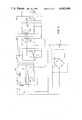
- FIG. 1is a block diagram illustrating the control schematic of a preferred embodiment of the self-adjusting ballast system.
- FIG. 2 and FIG. 3are circuit diagrams of the above preferred embodiment of the invention.
- FIG. 1illustrates in a schematic block diagram fashion the elements of a preferred embodiment of the self-adjusting ballast system utilizing an inverter with two switches, an autotransformer and a lamp circuit that has an inductor in series with the lamp as a current limiting means.
- the schemeassumes an input of either alternating current or direct current. If the input is alternating, AC to DC converter 10 rectifies in a traditional fashion the alternating wave into direct current waves.
- Optional power factor corrector 50may be added to input alternating current lines for line power factor correction. Connecting the DC power line through converter 10 yields a safety feature. The lines of the ballast system can not be connected incorrectly to a DC power source.
- Low voltage supply 12fed by input from converter 10, supplies low voltage direct current to an oscillator, a dead time controller and a pulse width modulator.
- Oscillator 16generates a high frequency signal, high at least in relation to the line frequency.
- the frequency of oscillator 16may be varied by dimmer 22.
- Dimmer 22in addition to being a manually set dimming device, could be a lamp operation controller set by a photo sensitive device observing the lamp to run the lamp at constant intensity, set by a photo sensitive device observing illuminated areas to maintain constant illumination, or set by a lamp circuit voltage sensor which together with current control sensors 54A and 54B could adjust the lamp for constant power consumption.
- the high frequency wave formed by oscillator 16is supplied to dead time controller 18 and pulse width modulator 20. Pulse width modulator 20 is also supplied with input from lamp sensor 36 and ambient light sensor 14.
- the output from ambient light sensor 14acts as an off and on switch, either not affecting the output of pulse width modulator 20, when the ambient environment is dark, or completely turning pulse width modulator 20 to an "off" state, when the ambient environment is light.
- Pulse width modulator 20responds to the input from lamp sensor 36 and produces a modulated output signal which is a function of the radiant energy or heat measured by lamp sensor 36. The degree of modulation is inversely proportional to the sensed radiant energy or heat.
- Dead time controller 18produces a modulated output signal to correspond to a maximum duty cycle of slightly less than one hundred percent. Such dead time controller provides a safety period to insure that switch controller 24 can not gate switches 28A and 28B on at the same time. As a result of dead time controller 18, switch control 24 must gate both switches 28A and 28B off for a minimum dead time each oscillating signal cycle.
- the pulse width modulatorseverly restricts current through the lamp circuit.
- Each switchis gated on only a small fraction of each duty cycle.
- the lamp's resistanceis very low.
- the light sensordetecting increased radiant energy or heat output, communicates with the pulse width modulator which in turn permits each switch to be gated on for a larger percent of each duty cycle.
- Lamp sensor 36detects the change in output of radiant energy or heat from the lamp and resets the ballast system automatically for the minimal current start-up and warm-up stage. Current is quickly cut back from the lamp (although the lamp will not be able to strike until it cools, a process that can take several minutes).
- Switch control 24combines the outputs of dead time controller 18 and pulse width modulator 20 and sends the wave form alternately to gate on switch 28A or switch 28B.
- Rise and fall time controls 56A and 56Bachieve a slow on/fast off of the gates of switches 28A and 28B to improve magnetic characteristics.
- Current sensors 54A and 54B in series with switches 28A and 28Bautomatically gate off each switch for that half cycle of the oscillator signal cycle when the switch current exceeds a certain safe value. The switch current may become excessive because of "bulb rectification" or exhibit imbalance because of lack of perfect magnetic symmetry in the transformer.
- Switches 28A and 28Bdetermine which primary of autotransformer 30 is being energized. An induced current of different voltage and of the same frequency is induced in the secondary of transformer 30 and thus in the circuit containing lamp 34 and current limiting inductor 32. The duty cycle for each half wave of the induced current in the lamp circuit is a function of the on and off times of switches 28A and 28B, which in turn is a function of the dead time controller 18 and pulse width modulator 20 of the switch driving means.
- the frequency of oscillator 16determines the frequency of the alternating current in the lamp circuit.
- the frequency of oscillator 16 and the voltage transformation performed by transformer 30 and tap 31are chosen to permit the selection of an efficient economical current limiting means, such as inductor 32, for the normal operating state for a given type and wattage of lamp.
- FIG. 2 and FIG. 3represent a more specific circuit diagram for the preferred embodiment of the self-adjusting ballast system illustrated in FIG. 1.
- the embodiment illustrated in FIG. 3utilizes a pulse width modulating subcircuit, 40, that is commercially available. Use of such circuit is convenient but not necessary.
- AC to DC converter 10consists of diode bridge rectifier 11.
- Snubber circuit 38is provided to accommodate surges in voltage in the primary transformer circuit due to the rapidly alternating current.
- error amplifier 13amplifies the input of line 17 which contains the output of a voltage divider incorporating lamp sensor 36.
- Error amplifier 15operates as a Schmitt trigger and performs the function of an on/off switch. Its output voltage is a function of the input from a voltage divider containing ambient light sensor 14. Error amplifier 15 either turns pulse width modulator comparator 20 to a continuous "off" state or does not effect the output of pulse width modulator comparator 20 at all.
- Pulse width modulator comparator 20when not turned to an "off” state by error amplifier 15, compares the input signal voltage from error amplifier 13, an amplified input from lamp sensor 36, with the variable periodic signal voltage generated by oscillator 16. During that part of the oscillator signal cycle that the variable periodic signal voltage is greater than the signal voltage supplied by error amplifier 13, pulse width modulator comparator 20 is turned to an "on" state.
- Dead time comparator 18compares the variable periodic signal voltage from oscillator 16 each cycle with a minimal set control level voltage and is turned to an "on" state for all but a small percentage of each signal cycle of oscillator 16.
- the logic of the pulse width modulator subcircuit 40combines the output of dead time comparator 18 with the output of pulse width modulator comparator 20 and permits NOR gates 42 and 44 to enable transistor switches 46 and 48 only when both comparators are turned in the "on" state.
- Dead time comparator 18generates the clock signal for flip flop 19, corresponding to the frequency of oscillator 16, so that output switch transistors 46 and 48 may be driven alternately through control of the flip flop by NOR gates 42 and 44.
- the output of the switch driver meansare two pulse width modulated signals, at the frequency of oscillator 16, which open and close switches 28A and 28B.
- Reference regulator 12generates a low voltage supply necessary to run the sensing electronics.
- Switches 21 and 23serve to provide a slow on/fast off switching scheme for power switches 28A and 28B.
- Switches 25 and 27provide current sensing and control of the current passing through switches 28A and 28B.
- the preferred embodimentillustrates only one arrangement of switches and transformer that achieves the purposes of an inverter in changing direct current of one voltage to high frequency alternating current of a different or the same voltage.
- switches and transformersor power converters
- Some such configurationsmight be a full bridge power converter, a fly-back power converter with optional clamp windings, a half-bridge power converter with split windings, a half-bridge power converter or a forward power converter.
- the means to sense the lamp's emitted radiant energy or heatmight be any number of photo sensitive or thermistor devices.
- the preferred embodimentutilizes a cadmium sulfide cell.
Landscapes
- Circuit Arrangements For Discharge Lamps (AREA)
Abstract
Description
Claims (6)
Priority Applications (7)
| Application Number | Priority Date | Filing Date | Title |
|---|---|---|---|
| US06/770,663US4682084A (en) | 1985-08-28 | 1985-08-28 | High intensity discharge lamp self-adjusting ballast system sensitive to the radiant energy or heat of the lamp |
| JP61026052AJPS6251193A (en) | 1985-08-28 | 1986-02-10 | High-intensity discharge lamp self-adjusting stabilizer system sensitive to heat and radiant energy of lamp |
| US06/875,724US4686428A (en) | 1985-08-28 | 1986-06-18 | High intensity discharge lamp self-adjusting ballast system with current limiters and a current feedback loop |
| EP86904592AEP0235174A1 (en) | 1985-08-28 | 1986-06-30 | A high intensity discharge lamp self-adjusting ballast system sensitive to the radiant energy or heat of the lamp |
| DE1986904592DE235174T1 (en) | 1985-08-28 | 1986-06-30 | SELF-REGULATING CONTROL BALL CHASSIS SYSTEM RESPECTING THE RADIATION ENERGY OR HEAT OF A HIGH CURRENT DISCHARGE LAMP. |
| PCT/US1986/001380WO1987001553A1 (en) | 1985-08-28 | 1986-06-30 | A high intensity discharge lamp self-adjusting ballast system sensitive to the radiant energy or heat of the lamp |
| IL79833AIL79833A0 (en) | 1985-08-28 | 1986-08-25 | Self-adjusting ballast system for high-intensity discharge lamps |
Applications Claiming Priority (1)
| Application Number | Priority Date | Filing Date | Title |
|---|---|---|---|
| US06/770,663US4682084A (en) | 1985-08-28 | 1985-08-28 | High intensity discharge lamp self-adjusting ballast system sensitive to the radiant energy or heat of the lamp |
Related Child Applications (1)
| Application Number | Title | Priority Date | Filing Date |
|---|---|---|---|
| US06/875,724Continuation-In-PartUS4686428A (en) | 1985-08-28 | 1986-06-18 | High intensity discharge lamp self-adjusting ballast system with current limiters and a current feedback loop |
Publications (1)
| Publication Number | Publication Date |
|---|---|
| US4682084Atrue US4682084A (en) | 1987-07-21 |
Family
ID=25089295
Family Applications (1)
| Application Number | Title | Priority Date | Filing Date |
|---|---|---|---|
| US06/770,663Expired - LifetimeUS4682084A (en) | 1985-08-28 | 1985-08-28 | High intensity discharge lamp self-adjusting ballast system sensitive to the radiant energy or heat of the lamp |
Country Status (5)
| Country | Link |
|---|---|
| US (1) | US4682084A (en) |
| EP (1) | EP0235174A1 (en) |
| JP (1) | JPS6251193A (en) |
| IL (1) | IL79833A0 (en) |
| WO (1) | WO1987001553A1 (en) |
Cited By (43)
| Publication number | Priority date | Publication date | Assignee | Title |
|---|---|---|---|---|
| US4723098A (en)* | 1980-10-07 | 1988-02-02 | Thomas Industries, Inc. | Electronic ballast circuit for fluorescent lamps |
| US4873471A (en)* | 1986-03-28 | 1989-10-10 | Thomas Industries Inc. | High frequency ballast for gaseous discharge lamps |
| US4939421A (en)* | 1986-06-23 | 1990-07-03 | Motorola, Inc. | Method and apparatus for reducing interference from light sources |
| US4959755A (en)* | 1989-02-13 | 1990-09-25 | Hochstein Peter A | Automatic battery powered video light |
| US4998046A (en)* | 1989-06-05 | 1991-03-05 | Gte Products Corporation | Synchronized lamp ballast with dimming |
| US4999547A (en) | 1986-09-25 | 1991-03-12 | Innovative Controls, Incorporated | Ballast for high pressure sodium lamps having constant line and lamp wattage |
| US5012392A (en)* | 1989-02-13 | 1991-04-30 | Hochstein Peter A | Automatic battery powered video light |
| US5041767A (en)* | 1990-03-30 | 1991-08-20 | Bertonee Inc. | Digital controller for gas discharge tube |
| US5045758A (en)* | 1990-04-25 | 1991-09-03 | Hildebrand Cleve R | Solid state regulated power supply for luminescent lamp |
| US5081451A (en)* | 1988-10-20 | 1992-01-14 | Diesel Kiki Co., Ltd. | Display system for use in vehicle |
| GB2253077A (en)* | 1991-01-23 | 1992-08-26 | Carl Edmund Smith | Power control system for gas discharge tubes |
| US5155415A (en)* | 1990-09-26 | 1992-10-13 | Litebeams, Inc. | High voltage driver for gas discharge lamps |
| US5345148A (en)* | 1992-02-18 | 1994-09-06 | Singapore Institute Of Standards And Industrial Research | DC-AC converter for igniting and supplying a gas discharge lamp |
| US5386181A (en)* | 1992-01-24 | 1995-01-31 | Neon Dynamics Corporation | Swept frequency switching excitation supply for gas discharge tubes |
| US5401394A (en)* | 1993-01-11 | 1995-03-28 | Amway Corporation | Water treatment system ultraviolet bulb voltage monitor circuit |
| US5428265A (en)* | 1994-02-28 | 1995-06-27 | Honeywell, Inc. | Processor controlled fluorescent lamp dimmer for aircraft liquid crystal display instruments |
| US5438239A (en)* | 1980-08-14 | 1995-08-01 | Nilssen; Ole K. | Fluorescent lamp ballast with light output control |
| US5446347A (en)* | 1978-03-20 | 1995-08-29 | Nilssen; Ole K. | Electronic ballast with special DC supply |
| US5461285A (en)* | 1989-06-30 | 1995-10-24 | U.S. Philips Corporation | Switching arrangement |
| US5523656A (en)* | 1991-04-10 | 1996-06-04 | U.S. Philips Corporation | High pressure discharge lamp operating circuit with light control during lamp run up |
| US5536395A (en)* | 1993-03-22 | 1996-07-16 | Amway Corporation | Home water purification system with automatic disconnecting of radiant energy source |
| US5548188A (en)* | 1992-10-02 | 1996-08-20 | Samsung Electronics Co., Ltd. | Apparatus and method for controlling illumination of lamp |
| WO1997034464A1 (en)* | 1996-03-18 | 1997-09-25 | Gad Products, S.A. De C.V. | High-efficiency self-regulated electronic ballast with a single characteristic curve for operating high-pressure sodium vapour lamps |
| EP0677983A3 (en)* | 1994-04-13 | 1997-12-10 | General Electric Company | Gas discharge lamp ballast circuit with automatically calibrated light feedback control |
| US5698952A (en)* | 1995-03-29 | 1997-12-16 | Stebbins; Russell T. | Method and apparatus for direct current pulsed ionization lighting |
| US5925985A (en)* | 1996-07-27 | 1999-07-20 | Singapore Productivity And Standards Board | Electronic ballast circuit for igniting, supplying and dimming a gas discharge lamp |
| US6069448A (en)* | 1997-10-16 | 2000-05-30 | Twinhead International Corp. | LCD backlight converter having a temperature compensating means for regulating brightness |
| US6181071B1 (en)* | 1997-02-28 | 2001-01-30 | Mitsubishi Denki Kabushiki Kaisha | Display panel apparatus having reduced capacitive coupling |
| US20020180380A1 (en)* | 1999-07-22 | 2002-12-05 | Yung-Lin Lin | High-efficiency adaptive DC/AC converter |
| US6495969B1 (en)* | 1987-08-03 | 2002-12-17 | Ole K. Nilssen | Series-resonant ballast having overload control |
| US20040217716A1 (en)* | 2002-04-12 | 2004-11-04 | Mingfu Gong | System and method for preventing acoustc arc resonance in a HID lamp |
| US6815906B1 (en)* | 1997-05-07 | 2004-11-09 | David John Aarons | Gas discharge lamp drive circuitry |
| US20040240208A1 (en)* | 2003-06-02 | 2004-12-02 | Delta Power Supply, Inc. | Lumen sensing system |
| US20050174818A1 (en)* | 2004-02-11 | 2005-08-11 | Yung-Lin Lin | Liquid crystal display system with lamp feedback |
| GB2411971A (en)* | 2004-03-10 | 2005-09-14 | Cableform Ltd | Power factor adjustment |
| US20050225256A1 (en)* | 2003-10-01 | 2005-10-13 | Scolaro Martin S | Method and apparatus for lamp heat control |
| US20060273744A1 (en)* | 2005-05-25 | 2006-12-07 | Kurt Callewaert | Projector lamp control for increased lamp life |
| US7355354B2 (en) | 1998-12-11 | 2008-04-08 | Monolithic Power Systems, Inc. | Method for starting a discharge lamp using high energy initial pulse |
| US7417382B2 (en) | 1999-07-22 | 2008-08-26 | O2Micro International Limited | High-efficiency adaptive DC/AC converter |
| US20080316743A1 (en)* | 2007-06-19 | 2008-12-25 | Qualite Lighting, Inc. | Remote controlled athletic field lighting system |
| US7515446B2 (en) | 2002-04-24 | 2009-04-07 | O2Micro International Limited | High-efficiency adaptive DC/AC converter |
| US20090206775A1 (en)* | 2005-10-17 | 2009-08-20 | Green John D | Constant Lumen Output Control System |
| CN103857105A (en)* | 2012-11-30 | 2014-06-11 | 深圳市海洋王照明工程有限公司 | Control circuit |
Families Citing this family (3)
| Publication number | Priority date | Publication date | Assignee | Title |
|---|---|---|---|---|
| JPH01302696A (en)* | 1988-05-30 | 1989-12-06 | Hotonikusu:Kk | Dimming device for discharge lamp |
| EP0445757A3 (en)* | 1990-03-07 | 1992-04-08 | Tdk Corporation | Electric discharge lamp unit |
| JP2774010B2 (en)* | 1992-02-07 | 1998-07-09 | スガ試験機株式会社 | Xenon lamp protection circuit |
Citations (51)
| Publication number | Priority date | Publication date | Assignee | Title |
|---|---|---|---|---|
| US3222572A (en)* | 1962-07-23 | 1965-12-07 | Gen Electric | Apparatus for operating electric discharge devices |
| US3247422A (en)* | 1961-06-01 | 1966-04-19 | Gen Electric | Transistor inverter ballasting circuit |
| US3259797A (en)* | 1962-12-05 | 1966-07-05 | Engelhard Ind Inc | Arc lamp starter |
| US3265930A (en)* | 1962-05-03 | 1966-08-09 | Gen Electric | Current level switching apparatus for operating electric discharge lamps |
| US3309567A (en)* | 1965-10-22 | 1967-03-14 | Berkey Photo Inc | Pulse discharge lamp circuit |
| US3449629A (en)* | 1968-05-16 | 1969-06-10 | Westinghouse Electric Corp | Light,heat and temperature control systems |
| US3486070A (en)* | 1968-04-29 | 1969-12-23 | Westinghouse Electric Corp | Solid-state constant power ballast for electric discharge device |
| US3541421A (en)* | 1968-07-10 | 1970-11-17 | Union Carbide Corp | High power factor circuit for reactive loads |
| US3582708A (en)* | 1969-02-25 | 1971-06-01 | Esquire Inc | Continuous lighting systems for gaseous-discharge lamps with incandescent lamps on standby |
| US3590316A (en)* | 1969-03-17 | 1971-06-29 | Westinghouse Electric Corp | Phase-controlled universal ballast for discharge devices |
| US3619713A (en)* | 1969-04-01 | 1971-11-09 | Sola Basic Ind Inc | High-frequency lamp circuit for copying apparatus |
| US3659146A (en)* | 1970-02-20 | 1972-04-25 | Emerson Electric Co | Auxiliary lighting system for use particularly with high pressure metal vapor lamps |
| US3681654A (en)* | 1971-02-18 | 1972-08-01 | Wagner Electric Corp | Light-regulating power supply circuit for gaseous discharge lamp |
| US3753071A (en)* | 1972-06-15 | 1973-08-14 | Westinghouse Electric Corp | Low cost transistorized inverter |
| US3754160A (en)* | 1971-10-28 | 1973-08-21 | Radiant Ind Inc | Four-lamp driver circuit for fluorescent lamps |
| US3870943A (en)* | 1972-08-17 | 1975-03-11 | Bell Telephone Labor Inc | Converter circuit with correction circuitry to maintain signal symmetry in the switching devices |
| US3873882A (en)* | 1973-10-05 | 1975-03-25 | Leviton Manufacturing Co | Auxiliary lighting system for a gaseous discharge lamp |
| US3876855A (en)* | 1972-02-18 | 1975-04-08 | Matsushita Electric Industrial Co Ltd | Tungsten inert gas arc striking device |
| US3882354A (en)* | 1973-07-23 | 1975-05-06 | Coleman Company | Inverter ballast circuit for fluorescent lamp |
| US3886045A (en)* | 1972-05-12 | 1975-05-27 | Franco Meiattini | Process for the enzymatic determination of glucose with a glucose-oxidase/peroxidase enzyme system |
| US3890537A (en)* | 1974-01-02 | 1975-06-17 | Gen Electric | Solid state chopper ballast for gaseous discharge lamps |
| US3906302A (en)* | 1972-01-19 | 1975-09-16 | Philips Corp | Arrangement provided with a gas and/or vapour discharge lamp |
| US3927349A (en)* | 1974-04-11 | 1975-12-16 | Us Air Force | Zero crossing SCR light dimmer |
| US3927348A (en)* | 1973-07-17 | 1975-12-16 | Ram Meter Inc | Control circuits for auxiliary light source for use with high intensity discharge lamps |
| US3944876A (en)* | 1974-09-30 | 1976-03-16 | Chadwick-Helmuth Company, Inc. | Rapid starting of gas discharge lamps |
| US3967159A (en)* | 1975-02-03 | 1976-06-29 | Morton B. Leskin | Power supply for a laser or gas discharge lamp |
| US3969652A (en)* | 1974-01-04 | 1976-07-13 | General Electric Company | Electronic ballast for gaseous discharge lamps |
| US3999100A (en)* | 1975-05-19 | 1976-12-21 | Morton B. Leskin | Lamp power supply using a switching regulator and commutator |
| US4004187A (en)* | 1974-10-21 | 1977-01-18 | General Electric Company | Push-pull inverter ballast for arc discharge lamps |
| US4004188A (en)* | 1975-09-26 | 1977-01-18 | General Electric Company | Starting circuit for inverter operated gaseous discharge lamps |
| US4016451A (en)* | 1975-03-13 | 1977-04-05 | Westinghouse Electric Corporation | High pressure discharge lamp dimming circuit utilizing variable duty-cycle photocoupler |
| US4023067A (en)* | 1973-09-20 | 1977-05-10 | Lighting Systems, Inc. | Inverter ballast circuit |
| US4039897A (en)* | 1976-03-08 | 1977-08-02 | Dragoset James E | System for controlling power applied to a gas discharge lamp |
| US4042856A (en)* | 1975-10-28 | 1977-08-16 | General Electric Company | Chopper ballast for gaseous discharge lamps with auxiliary capacitor energy storage |
| US4051413A (en)* | 1976-05-26 | 1977-09-27 | Abadie Henry J L | Transistorized static inverters |
| US4060751A (en)* | 1976-03-01 | 1977-11-29 | General Electric Company | Dual mode solid state inverter circuit for starting and ballasting gas discharge lamps |
| US4060752A (en)* | 1976-03-01 | 1977-11-29 | General Electric Company | Discharge lamp auxiliary circuit with dI/dt switching control |
| US4066930A (en)* | 1975-04-02 | 1978-01-03 | Electrides Corporation | Energizing circuits for fluorescent lamps |
| US4074170A (en)* | 1976-06-21 | 1978-02-14 | Vivitar Corporation | Voltage regulator with thermal overload protection |
| US4087702A (en)* | 1976-03-09 | 1978-05-02 | Kirby James P | Digital electronic dimmer |
| US4100462A (en)* | 1977-05-11 | 1978-07-11 | Mclellan Norvel Jeff | Combination incandescent/fluorescent lighting system |
| US4121136A (en)* | 1976-05-18 | 1978-10-17 | Etat Francais | Apparatus for feeding discharge lamps from a direct current source |
| US4127795A (en)* | 1977-08-19 | 1978-11-28 | Gte Sylvania Incorporated | Lamp ballast circuit |
| US4127789A (en)* | 1976-10-28 | 1978-11-28 | U.S. Philips Corporation | Light-pervious, heat-reflecting filter and electric lamps having such a filter |
| US4145636A (en)* | 1976-08-09 | 1979-03-20 | I. S. Engineering Co., Ltd. | Fluorescent lamp driving circuit |
| US4151445A (en)* | 1978-02-15 | 1979-04-24 | General Electric Company | Instant light lamp control circuit |
| US4414493A (en)* | 1981-10-06 | 1983-11-08 | Thomas Industries Inc. | Light dimmer for solid state ballast |
| US4415839A (en)* | 1981-11-23 | 1983-11-15 | Lesea Ronald A | Electronic ballast for gaseous discharge lamps |
| US4464606A (en)* | 1981-03-25 | 1984-08-07 | Armstrong World Industries, Inc. | Pulse width modulated dimming arrangement for fluorescent lamps |
| US4485434A (en)* | 1981-07-28 | 1984-11-27 | Lee Electric (Lighting) Limited | Power supply for arc lamps |
| US4585974A (en)* | 1983-01-03 | 1986-04-29 | North American Philips Corporation | Varible frequency current control device for discharge lamps |
Family Cites Families (2)
| Publication number | Priority date | Publication date | Assignee | Title |
|---|---|---|---|---|
| US4346331A (en)* | 1980-05-27 | 1982-08-24 | Enertron, Inc. | Feedback control system for applying AC power to ballasted lamps |
| US4498031A (en)* | 1983-01-03 | 1985-02-05 | North American Philips Corporation | Variable frequency current control device for discharge lamps |
- 1985
- 1985-08-28USUS06/770,663patent/US4682084A/ennot_activeExpired - Lifetime
- 1986
- 1986-02-10JPJP61026052Apatent/JPS6251193A/enactivePending
- 1986-06-30EPEP86904592Apatent/EP0235174A1/ennot_activeWithdrawn
- 1986-06-30WOPCT/US1986/001380patent/WO1987001553A1/ennot_activeApplication Discontinuation
- 1986-08-25ILIL79833Apatent/IL79833A0/enunknown
Patent Citations (51)
| Publication number | Priority date | Publication date | Assignee | Title |
|---|---|---|---|---|
| US3247422A (en)* | 1961-06-01 | 1966-04-19 | Gen Electric | Transistor inverter ballasting circuit |
| US3265930A (en)* | 1962-05-03 | 1966-08-09 | Gen Electric | Current level switching apparatus for operating electric discharge lamps |
| US3222572A (en)* | 1962-07-23 | 1965-12-07 | Gen Electric | Apparatus for operating electric discharge devices |
| US3259797A (en)* | 1962-12-05 | 1966-07-05 | Engelhard Ind Inc | Arc lamp starter |
| US3309567A (en)* | 1965-10-22 | 1967-03-14 | Berkey Photo Inc | Pulse discharge lamp circuit |
| US3486070A (en)* | 1968-04-29 | 1969-12-23 | Westinghouse Electric Corp | Solid-state constant power ballast for electric discharge device |
| US3449629A (en)* | 1968-05-16 | 1969-06-10 | Westinghouse Electric Corp | Light,heat and temperature control systems |
| US3541421A (en)* | 1968-07-10 | 1970-11-17 | Union Carbide Corp | High power factor circuit for reactive loads |
| US3582708A (en)* | 1969-02-25 | 1971-06-01 | Esquire Inc | Continuous lighting systems for gaseous-discharge lamps with incandescent lamps on standby |
| US3590316A (en)* | 1969-03-17 | 1971-06-29 | Westinghouse Electric Corp | Phase-controlled universal ballast for discharge devices |
| US3619713A (en)* | 1969-04-01 | 1971-11-09 | Sola Basic Ind Inc | High-frequency lamp circuit for copying apparatus |
| US3659146A (en)* | 1970-02-20 | 1972-04-25 | Emerson Electric Co | Auxiliary lighting system for use particularly with high pressure metal vapor lamps |
| US3681654A (en)* | 1971-02-18 | 1972-08-01 | Wagner Electric Corp | Light-regulating power supply circuit for gaseous discharge lamp |
| US3754160A (en)* | 1971-10-28 | 1973-08-21 | Radiant Ind Inc | Four-lamp driver circuit for fluorescent lamps |
| US3906302A (en)* | 1972-01-19 | 1975-09-16 | Philips Corp | Arrangement provided with a gas and/or vapour discharge lamp |
| US3876855A (en)* | 1972-02-18 | 1975-04-08 | Matsushita Electric Industrial Co Ltd | Tungsten inert gas arc striking device |
| US3886045A (en)* | 1972-05-12 | 1975-05-27 | Franco Meiattini | Process for the enzymatic determination of glucose with a glucose-oxidase/peroxidase enzyme system |
| US3753071A (en)* | 1972-06-15 | 1973-08-14 | Westinghouse Electric Corp | Low cost transistorized inverter |
| US3870943A (en)* | 1972-08-17 | 1975-03-11 | Bell Telephone Labor Inc | Converter circuit with correction circuitry to maintain signal symmetry in the switching devices |
| US3927348A (en)* | 1973-07-17 | 1975-12-16 | Ram Meter Inc | Control circuits for auxiliary light source for use with high intensity discharge lamps |
| US3882354A (en)* | 1973-07-23 | 1975-05-06 | Coleman Company | Inverter ballast circuit for fluorescent lamp |
| US4023067A (en)* | 1973-09-20 | 1977-05-10 | Lighting Systems, Inc. | Inverter ballast circuit |
| US3873882A (en)* | 1973-10-05 | 1975-03-25 | Leviton Manufacturing Co | Auxiliary lighting system for a gaseous discharge lamp |
| US3890537A (en)* | 1974-01-02 | 1975-06-17 | Gen Electric | Solid state chopper ballast for gaseous discharge lamps |
| US3969652A (en)* | 1974-01-04 | 1976-07-13 | General Electric Company | Electronic ballast for gaseous discharge lamps |
| US3927349A (en)* | 1974-04-11 | 1975-12-16 | Us Air Force | Zero crossing SCR light dimmer |
| US3944876A (en)* | 1974-09-30 | 1976-03-16 | Chadwick-Helmuth Company, Inc. | Rapid starting of gas discharge lamps |
| US4004187A (en)* | 1974-10-21 | 1977-01-18 | General Electric Company | Push-pull inverter ballast for arc discharge lamps |
| US3967159A (en)* | 1975-02-03 | 1976-06-29 | Morton B. Leskin | Power supply for a laser or gas discharge lamp |
| US4016451A (en)* | 1975-03-13 | 1977-04-05 | Westinghouse Electric Corporation | High pressure discharge lamp dimming circuit utilizing variable duty-cycle photocoupler |
| US4066930A (en)* | 1975-04-02 | 1978-01-03 | Electrides Corporation | Energizing circuits for fluorescent lamps |
| US3999100A (en)* | 1975-05-19 | 1976-12-21 | Morton B. Leskin | Lamp power supply using a switching regulator and commutator |
| US4004188A (en)* | 1975-09-26 | 1977-01-18 | General Electric Company | Starting circuit for inverter operated gaseous discharge lamps |
| US4042856A (en)* | 1975-10-28 | 1977-08-16 | General Electric Company | Chopper ballast for gaseous discharge lamps with auxiliary capacitor energy storage |
| US4060751A (en)* | 1976-03-01 | 1977-11-29 | General Electric Company | Dual mode solid state inverter circuit for starting and ballasting gas discharge lamps |
| US4060752A (en)* | 1976-03-01 | 1977-11-29 | General Electric Company | Discharge lamp auxiliary circuit with dI/dt switching control |
| US4039897A (en)* | 1976-03-08 | 1977-08-02 | Dragoset James E | System for controlling power applied to a gas discharge lamp |
| US4087702A (en)* | 1976-03-09 | 1978-05-02 | Kirby James P | Digital electronic dimmer |
| US4121136A (en)* | 1976-05-18 | 1978-10-17 | Etat Francais | Apparatus for feeding discharge lamps from a direct current source |
| US4051413A (en)* | 1976-05-26 | 1977-09-27 | Abadie Henry J L | Transistorized static inverters |
| US4074170A (en)* | 1976-06-21 | 1978-02-14 | Vivitar Corporation | Voltage regulator with thermal overload protection |
| US4145636A (en)* | 1976-08-09 | 1979-03-20 | I. S. Engineering Co., Ltd. | Fluorescent lamp driving circuit |
| US4127789A (en)* | 1976-10-28 | 1978-11-28 | U.S. Philips Corporation | Light-pervious, heat-reflecting filter and electric lamps having such a filter |
| US4100462A (en)* | 1977-05-11 | 1978-07-11 | Mclellan Norvel Jeff | Combination incandescent/fluorescent lighting system |
| US4127795A (en)* | 1977-08-19 | 1978-11-28 | Gte Sylvania Incorporated | Lamp ballast circuit |
| US4151445A (en)* | 1978-02-15 | 1979-04-24 | General Electric Company | Instant light lamp control circuit |
| US4464606A (en)* | 1981-03-25 | 1984-08-07 | Armstrong World Industries, Inc. | Pulse width modulated dimming arrangement for fluorescent lamps |
| US4485434A (en)* | 1981-07-28 | 1984-11-27 | Lee Electric (Lighting) Limited | Power supply for arc lamps |
| US4414493A (en)* | 1981-10-06 | 1983-11-08 | Thomas Industries Inc. | Light dimmer for solid state ballast |
| US4415839A (en)* | 1981-11-23 | 1983-11-15 | Lesea Ronald A | Electronic ballast for gaseous discharge lamps |
| US4585974A (en)* | 1983-01-03 | 1986-04-29 | North American Philips Corporation | Varible frequency current control device for discharge lamps |
Cited By (58)
| Publication number | Priority date | Publication date | Assignee | Title |
|---|---|---|---|---|
| US5446347A (en)* | 1978-03-20 | 1995-08-29 | Nilssen; Ole K. | Electronic ballast with special DC supply |
| US5757140A (en)* | 1978-03-20 | 1998-05-26 | Nilssen; Ole K. | Electronic ballast with frequency control |
| US5438239A (en)* | 1980-08-14 | 1995-08-01 | Nilssen; Ole K. | Fluorescent lamp ballast with light output control |
| US4723098A (en)* | 1980-10-07 | 1988-02-02 | Thomas Industries, Inc. | Electronic ballast circuit for fluorescent lamps |
| US4873471A (en)* | 1986-03-28 | 1989-10-10 | Thomas Industries Inc. | High frequency ballast for gaseous discharge lamps |
| US4939421A (en)* | 1986-06-23 | 1990-07-03 | Motorola, Inc. | Method and apparatus for reducing interference from light sources |
| US4999547A (en) | 1986-09-25 | 1991-03-12 | Innovative Controls, Incorporated | Ballast for high pressure sodium lamps having constant line and lamp wattage |
| US6495969B1 (en)* | 1987-08-03 | 2002-12-17 | Ole K. Nilssen | Series-resonant ballast having overload control |
| US5081451A (en)* | 1988-10-20 | 1992-01-14 | Diesel Kiki Co., Ltd. | Display system for use in vehicle |
| US4959755A (en)* | 1989-02-13 | 1990-09-25 | Hochstein Peter A | Automatic battery powered video light |
| US5012392A (en)* | 1989-02-13 | 1991-04-30 | Hochstein Peter A | Automatic battery powered video light |
| US4998046A (en)* | 1989-06-05 | 1991-03-05 | Gte Products Corporation | Synchronized lamp ballast with dimming |
| US5461285A (en)* | 1989-06-30 | 1995-10-24 | U.S. Philips Corporation | Switching arrangement |
| US5041767A (en)* | 1990-03-30 | 1991-08-20 | Bertonee Inc. | Digital controller for gas discharge tube |
| US5045758A (en)* | 1990-04-25 | 1991-09-03 | Hildebrand Cleve R | Solid state regulated power supply for luminescent lamp |
| US5155415A (en)* | 1990-09-26 | 1992-10-13 | Litebeams, Inc. | High voltage driver for gas discharge lamps |
| GB2253077A (en)* | 1991-01-23 | 1992-08-26 | Carl Edmund Smith | Power control system for gas discharge tubes |
| US5523656A (en)* | 1991-04-10 | 1996-06-04 | U.S. Philips Corporation | High pressure discharge lamp operating circuit with light control during lamp run up |
| US5386181A (en)* | 1992-01-24 | 1995-01-31 | Neon Dynamics Corporation | Swept frequency switching excitation supply for gas discharge tubes |
| US5345148A (en)* | 1992-02-18 | 1994-09-06 | Singapore Institute Of Standards And Industrial Research | DC-AC converter for igniting and supplying a gas discharge lamp |
| US5548188A (en)* | 1992-10-02 | 1996-08-20 | Samsung Electronics Co., Ltd. | Apparatus and method for controlling illumination of lamp |
| US5401394A (en)* | 1993-01-11 | 1995-03-28 | Amway Corporation | Water treatment system ultraviolet bulb voltage monitor circuit |
| US5698091A (en)* | 1993-03-22 | 1997-12-16 | Amway Corporation | Home water purification system with filter end of life monitor |
| US5536395A (en)* | 1993-03-22 | 1996-07-16 | Amway Corporation | Home water purification system with automatic disconnecting of radiant energy source |
| US5853572A (en)* | 1993-03-22 | 1998-12-29 | Amway Corporation | Home water purification system |
| US5428265A (en)* | 1994-02-28 | 1995-06-27 | Honeywell, Inc. | Processor controlled fluorescent lamp dimmer for aircraft liquid crystal display instruments |
| EP0677983A3 (en)* | 1994-04-13 | 1997-12-10 | General Electric Company | Gas discharge lamp ballast circuit with automatically calibrated light feedback control |
| US5698952A (en)* | 1995-03-29 | 1997-12-16 | Stebbins; Russell T. | Method and apparatus for direct current pulsed ionization lighting |
| US6137238A (en)* | 1996-03-18 | 2000-10-24 | Alvarez; Eduardo Salman | High-efficiency self-regulated electronic ballast with a single characteristic curve for operating high-pressure sodium vapor lamps |
| WO1997034464A1 (en)* | 1996-03-18 | 1997-09-25 | Gad Products, S.A. De C.V. | High-efficiency self-regulated electronic ballast with a single characteristic curve for operating high-pressure sodium vapour lamps |
| US5925985A (en)* | 1996-07-27 | 1999-07-20 | Singapore Productivity And Standards Board | Electronic ballast circuit for igniting, supplying and dimming a gas discharge lamp |
| US6181071B1 (en)* | 1997-02-28 | 2001-01-30 | Mitsubishi Denki Kabushiki Kaisha | Display panel apparatus having reduced capacitive coupling |
| US6815906B1 (en)* | 1997-05-07 | 2004-11-09 | David John Aarons | Gas discharge lamp drive circuitry |
| US6069448A (en)* | 1997-10-16 | 2000-05-30 | Twinhead International Corp. | LCD backlight converter having a temperature compensating means for regulating brightness |
| US7355354B2 (en) | 1998-12-11 | 2008-04-08 | Monolithic Power Systems, Inc. | Method for starting a discharge lamp using high energy initial pulse |
| US7880397B2 (en) | 1998-12-11 | 2011-02-01 | Monolithic Power Systems, Inc. | Method for starting a discharge lamp using high energy initial pulse |
| US20020180380A1 (en)* | 1999-07-22 | 2002-12-05 | Yung-Lin Lin | High-efficiency adaptive DC/AC converter |
| US7881084B2 (en) | 1999-07-22 | 2011-02-01 | O2Micro International Limited | DC/AC cold cathode fluorescent lamp inverter |
| US7515445B2 (en) | 1999-07-22 | 2009-04-07 | 02Micro International Limited | High-efficiency adaptive DC/AC converter |
| US20080246413A1 (en)* | 1999-07-22 | 2008-10-09 | O2Micro, Inc. | Dc/ac cold cathode fluorescent lamp inverter |
| US7417382B2 (en) | 1999-07-22 | 2008-08-26 | O2Micro International Limited | High-efficiency adaptive DC/AC converter |
| US20040217716A1 (en)* | 2002-04-12 | 2004-11-04 | Mingfu Gong | System and method for preventing acoustc arc resonance in a HID lamp |
| US7084578B2 (en)* | 2002-04-12 | 2006-08-01 | Mingfu Gong | System and method for preventing acoustic arc resonance in a HID lamp |
| US7515446B2 (en) | 2002-04-24 | 2009-04-07 | O2Micro International Limited | High-efficiency adaptive DC/AC converter |
| US20040240208A1 (en)* | 2003-06-02 | 2004-12-02 | Delta Power Supply, Inc. | Lumen sensing system |
| US20050225256A1 (en)* | 2003-10-01 | 2005-10-13 | Scolaro Martin S | Method and apparatus for lamp heat control |
| US7372210B2 (en) | 2003-10-01 | 2008-05-13 | Snap-On Incorporated | Method and apparatus for lamp heat control |
| US20050174818A1 (en)* | 2004-02-11 | 2005-08-11 | Yung-Lin Lin | Liquid crystal display system with lamp feedback |
| US7394209B2 (en) | 2004-02-11 | 2008-07-01 | 02 Micro International Limited | Liquid crystal display system with lamp feedback |
| GB2411971B (en)* | 2004-03-10 | 2006-09-06 | Cableform Ltd | Power factor improvement |
| GB2411971A (en)* | 2004-03-10 | 2005-09-14 | Cableform Ltd | Power factor adjustment |
| US7432667B2 (en)* | 2005-05-25 | 2008-10-07 | Barco N.V. | Projector lamp control for increased lamp life |
| US20060273744A1 (en)* | 2005-05-25 | 2006-12-07 | Kurt Callewaert | Projector lamp control for increased lamp life |
| US20090206775A1 (en)* | 2005-10-17 | 2009-08-20 | Green John D | Constant Lumen Output Control System |
| US8390211B2 (en) | 2005-10-17 | 2013-03-05 | Abl Ip Holding Llc | Constant lumen output control system |
| US20080316743A1 (en)* | 2007-06-19 | 2008-12-25 | Qualite Lighting, Inc. | Remote controlled athletic field lighting system |
| CN103857105A (en)* | 2012-11-30 | 2014-06-11 | 深圳市海洋王照明工程有限公司 | Control circuit |
| CN103857105B (en)* | 2012-11-30 | 2016-09-14 | 深圳市海洋王照明工程有限公司 | A kind of control circuit |
Also Published As
| Publication number | Publication date |
|---|---|
| EP0235174A1 (en) | 1987-09-09 |
| JPS6251193A (en) | 1987-03-05 |
| IL79833A0 (en) | 1986-11-30 |
| EP0235174A4 (en) | 1987-08-10 |
| WO1987001553A1 (en) | 1987-03-12 |
Similar Documents
| Publication | Publication Date | Title |
|---|---|---|
| US4682084A (en) | High intensity discharge lamp self-adjusting ballast system sensitive to the radiant energy or heat of the lamp | |
| US5235254A (en) | Fluorescent lamp supply circuit | |
| US4686428A (en) | High intensity discharge lamp self-adjusting ballast system with current limiters and a current feedback loop | |
| US4464606A (en) | Pulse width modulated dimming arrangement for fluorescent lamps | |
| EP0818129B1 (en) | Control and protection of dimmable electronic fluorescent lamp ballast with wide input voltage range and wide dimming range | |
| EP0233605B1 (en) | Frequency modulation ballast circuit | |
| US4999547A (en) | Ballast for high pressure sodium lamps having constant line and lamp wattage | |
| EP0765108B1 (en) | High intensity discharge lamp lighting device | |
| US4914356A (en) | Controller for gas discharge lamps | |
| US20050067973A1 (en) | Device for heating electrodes of a discharge lamp | |
| US5334915A (en) | Operating circuit arrangement for a discharge lamp | |
| US7279853B2 (en) | Fluorescent lamp dimmer control | |
| JPS6324638Y2 (en) | ||
| US20040021432A1 (en) | Frequency-modulated dimming control system of discharge lamp | |
| NO873333L (en) | ELECTRONIC BALLASTREACTANCE FOR HIGH-INTENSITY GAS EMISSIONS LAMPS. | |
| KR900006802B1 (en) | Arrangements for discharge lamps | |
| KR0165031B1 (en) | Lamp turn-on control method and device of a refrigerator | |
| KR0150539B1 (en) | Inverter type lighting device control circuit | |
| JPH0244698A (en) | discharge lamp lighting device | |
| JPH05109491A (en) | High-frequency lighting device | |
| CA1228115A (en) | Energizing circuit for fluorescent lamps | |
| JPH04292896A (en) | Discharge lamp lighting device | |
| JPH0785979A (en) | Disaster prevention lighting circuit and disaster prevention lighting device using the same | |
| JPH07235391A (en) | Dimming device of discharge lamp lighting device | |
| JPH0766863B2 (en) | Discharge lamp lighting device |
Legal Events
| Date | Code | Title | Description |
|---|---|---|---|
| AS | Assignment | Owner name:INNOVATIVE CONTROLS, INCORPORATED, Free format text:ASSIGNMENT OF ASSIGNORS INTEREST.;ASSIGNORS:KUHNEL, DONALD S.;OTTENSTEIN, SIDNEY A.;REEL/FRAME:004476/0001 Effective date:19850826 | |
| STCF | Information on status: patent grant | Free format text:PATENTED CASE | |
| CC | Certificate of correction | ||
| FEPP | Fee payment procedure | Free format text:PAYOR NUMBER ASSIGNED (ORIGINAL EVENT CODE: ASPN); ENTITY STATUS OF PATENT OWNER: LARGE ENTITY | |
| FPAY | Fee payment | Year of fee payment:4 | |
| FPAY | Fee payment | Year of fee payment:8 | |
| AS | Assignment | Owner name:THOMAS & BETTS INTERNATIONAL, INC., NEVADA Free format text:ASSIGNMENT OF ASSIGNORS INTEREST;ASSIGNOR:THOMAS & BETTS CORPORATION;REEL/FRAME:009445/0386 Effective date:19980902 | |
| FPAY | Fee payment | Year of fee payment:12 | |
| AS | Assignment | Owner name:ABL IP HOLDING LLC, GEORGIA Free format text:ASSIGNMENT OF ASSIGNORS INTEREST;ASSIGNOR:ACUITY BRANDS, INC.;REEL/FRAME:023438/0843 Effective date:20070926 Owner name:ACUITY BRANDS, INC., GEORGIA Free format text:CHANGE OF NAME;ASSIGNOR:L&C SPINCO;REEL/FRAME:023438/0834 Effective date:20011109 Owner name:L&C SPINCO, GEORGIA Free format text:ASSIGNMENT OF ASSIGNORS INTEREST;ASSIGNOR:THOMAS & BETTS INTERNATIONAL, INC.;REEL/FRAME:023438/0824 Effective date:20011012 |