US4681741A - Reagent dispenser for an analyzing system - Google Patents
Reagent dispenser for an analyzing systemDownload PDFInfo
- Publication number
- US4681741A US4681741AUS06/943,820US94382086AUS4681741AUS 4681741 AUS4681741 AUS 4681741AUS 94382086 AUS94382086 AUS 94382086AUS 4681741 AUS4681741 AUS 4681741A
- Authority
- US
- United States
- Prior art keywords
- reagent
- tray
- containers
- carousel
- dispensing
- Prior art date
- Legal status (The legal status is an assumption and is not a legal conclusion. Google has not performed a legal analysis and makes no representation as to the accuracy of the status listed.)
- Expired - Fee Related
Links
Images


Classifications
- G—PHYSICS
- G01—MEASURING; TESTING
- G01N—INVESTIGATING OR ANALYSING MATERIALS BY DETERMINING THEIR CHEMICAL OR PHYSICAL PROPERTIES
- G01N35/00—Automatic analysis not limited to methods or materials provided for in any single one of groups G01N1/00 - G01N33/00; Handling materials therefor
- G01N35/10—Devices for transferring samples or any liquids to, in, or from, the analysis apparatus, e.g. suction devices, injection devices
- G01N35/1095—Devices for transferring samples or any liquids to, in, or from, the analysis apparatus, e.g. suction devices, injection devices for supplying the samples to flow-through analysers
- G—PHYSICS
- G01—MEASURING; TESTING
- G01N—INVESTIGATING OR ANALYSING MATERIALS BY DETERMINING THEIR CHEMICAL OR PHYSICAL PROPERTIES
- G01N35/00—Automatic analysis not limited to methods or materials provided for in any single one of groups G01N1/00 - G01N33/00; Handling materials therefor
- G01N2035/00346—Heating or cooling arrangements
- G01N2035/00455—Controlling humidity in analyser
- G—PHYSICS
- G01—MEASURING; TESTING
- G01N—INVESTIGATING OR ANALYSING MATERIALS BY DETERMINING THEIR CHEMICAL OR PHYSICAL PROPERTIES
- G01N35/00—Automatic analysis not limited to methods or materials provided for in any single one of groups G01N1/00 - G01N33/00; Handling materials therefor
- G01N35/00584—Control arrangements for automatic analysers
- G01N35/00722—Communications; Identification
- G01N35/00732—Identification of carriers, materials or components in automatic analysers
- G01N2035/00742—Type of codes
- G01N2035/00752—Type of codes bar codes
Definitions
- This inventionrelates to a reagent dispenser apparatus for an automatic specimen analyzing system.
- Cross referenceis made to three other related copending applications assigned to the same assignee: patent application of William P. Armes, Andrew M. Cherniski, Richard W. Hanaway and James C. Hathaway entitled “Automatic Specimen Analyzing System” Ser. No. 750,792 filed July 1, 1985; and my two patent applications entitled “Tower for Analyzing System” Ser. No. 750,793 filed July 1, 1985 and entitled “Tray for Analyzing System” Ser. No. 750,794 filed July 1, 1985.
- This inventionrelates to an automatic specimen analyzing system which substantially reduces operator involvement over presently available systems. After the operator loads the specimen trays into the system of this invention, various operations including incubation after inoculation, adding reagents and analysis of the specimen following incubation are all handled automatically without further operator involvement.
- a computer-type processorcontrols the system so that the various operations are carried out in appropriate sequence and the results of the analysis are recorded with specific reference to the sample analyzed.
- the Pfizer Autobac 1 system(U.S. Pat. No. Re. 28,801) measures relative bacterial growth by light scatter at a fixed 35 degree angle. It includes twelve test chambers and one control chamber in a plastic device that forms multiple contiguous cuvettes. Antibiotics are introduced to the chambers via impregnated paper discs. The antimicrobic sensitivity reader comes with an incubator, shaker, and disc dispenser. Results are expressed as a light scattering index (LSI), and these numbers are related to the Kirby-Bauer "sensitive, intermediate and resistant.” MIC measurements which are not available routinely with this instrument. In a comparison with susceptibilities of clinical isolates measured by the Kirby-Bauer method, there was 91% agreement. However, with this system some bacteria strain-drug combinations have been found to produce a resistant Kirby-Bauer zone diameter and at the same time a sensitive LSI.
- LSIlight scattering index
- the Auto Microbic Systemhas been developed by McDonnell-Douglas to perform identification, enumeration and susceptibility studies on nine urinary tract pathogens using a plastic plate containing a 4 ⁇ 5 array of wells.
- McDonnell-DouglasSee Gibson et al, U.S. Pat. No. 3,957,583; Charles et al, U.S. Pat. No. 4,118,280, and Charles et al, U.S. Pat. No. 4,116,775.
- the specimenis drawn into the small wells by negative pressure and the instrument monitors the change in optical absorbance and scatter with light-emitting diodes and an array of optical sensors.
- a mechanical devicemoves each plate into a sensing slot in a continuous succession so that each plate is scanned at the rate of one an hour, and an onboard digital computer stores the optical data.
- the systemwill process either 120 or 240 specimens at a time.
- the systemdetects sufficient bacterial growth to permit a valid result, it automatically triggers a print-out.
- a technologisttransfers positive cultures to another system which tests for antimicrobic susceptibility. The results are expressed as "R" (resistant) and "S” (susceptible); however, no quantitative MIC data are provided.
- the Abbot MS-2 systemconsists of chambers composed of eleven contiguous cuvettes. Similar to the Pfizer Autobac 1, the antimicrobial compounds are introduced by way of impregnated paper discs. An inoculum consisting of a suspension of organisms from several colonies is introduced into the culture medium, and the cuvette cartridge is filled with this suspension. The operator inserts the cuvette cartridge into an analysis module which will handle eight cartridges (additional modules can be added to the system). Following agitation of the cartridge, the instrument monitors the growth rate by turbidimetry. When the low growth phase occurs, the system automatically transfers the broth solution to the eleven cuvette chambers; ten of these chambers contain antimicrobial discs while the eleventh is a growth control.
- the deviceperforms readings at five minute intervals, and stores the data in a microprocessor. Following a pre-set increase of turbidity of the growth control, the processor establishes a growth rate constant for each chamber. A comparison of the antimicrobic growth rate constant and control growth rate constant forms the basis of susceptibility calculations. The printout presents results as either resistant or susceptible and if intermediate, susceptibility information is expressed as an MIC.
- Non-optical methodshave also been used or suggested for measuring antimicrobic sensitivity in susceptibility testing. These have included radiorespirometry, electrical impedance, bioluminescence and microcalorimetry. Radiorespirometry, based on the principle that bacteria metabolized carbohydrate and the carbohydrate carbon may be detected following its release as CO 2 involves the incorporation of the isotope C-into carbohydrates. Released C 14 O 2 gas is trapped and beta counting techniques are used to detect the isotope.
- the major difficulty in applying the isotope detection system to susceptibility testngis that an antimicrobic agent may be able to stop growth of a species of bacteria, yet metabolism of carbohydrate may continue. Less likely, a given drug may turn off the metabolic machinery that metabolizes certain carbohydrates, but growth may continue. This dissociation between metabolism and cell growth emphasizes the fact that measurements for detecting antimicrobic susceptibility should depend upon a determination of cell mass or cell number rather than metabolism.
- the electrical impedance systemis based on the fact that bacterial cells have a low net charge and higher electrical impedance than the surrounding electrolytic bacterial growth media.
- a pulse impedance cell-counting devicecan be used to count the cells; however, available counting devices are not designed to handle batches of samples automatically, and generally do not have the capacity to distinguish between live and dead bacterial cells.
- Bioluminescencehas also been suggested for the detection of microorganisms. It is based on the principle that a nearly universal property of living organisms is the storage of energy in the form of high energy phosphates (adenosine triphosphate, ATP), which can be detected through reaction with firefly luciferase. The reaction results in the emission of light energy which can be detected with great sensitivity by electronic light transducers.
- ATPadenosine triphosphate
- Microcalorimetryis the measurement of minute amounts of heat generated by bacterial metabolism.
- the principleexhibits certain advantages, but laboratories have not adopted such a system, one serious drawback being that the system measures metabolic activity rather than bacterial mass or number.
- an automatic scanning apparatusfor performing optical density tests on liquid samples as well as methods for testing for antibiotic susceptibility and identifying microorganisms.
- the apparatus of the prior applicationincludes a system for automatically scanning electronically each well of a multi-well tray containing many liquid samples.
- a light sourcepreferably a single source, is passed through the wells to an array of photosensitive cells, one for each well.
- Electronic apparatusread each cell in sequence quickly completing the scan without physical movement of any parts.
- the resultant signalsare compared with the signals from a comparison cell and with other signals or stored data, and determinations are made and displayed or printed out.
- MicroScan Systemrepresents a substantial advancement in the automation of microbiological analysis, it still requires operator involvement to handle operations such as incubation, addition of reagents and insertion for the autoscan analysis operation.
- an operatorpresently in use, an operator must perform the operations of placing the tray in a suitable system for incubation for the desired period and after incubation, adding reagents and inserting the tray in the analyzer.
- all of these operation after insertion of the tray in the systemare carried out fully and automatically.
- a reagent dispenser assemblyfor use in an automated analysis system.
- the reagent delivery system in accordance with this inventionutilizes a plurality of remote reagent supply containers and a system for selectively dispensing the desired amount of reagent from the corresponding supply container.
- the systempreferably includes a remote dispensing head arranged at a work station for administering the reagents to specimen trays holding a plurality of specimen.
- the reagent dispenser assembly of this inventioncomprises a dispensing station having a plurality of reagent supply containers associated therewith. Means are provided for positioning a desired one of the reagent containers at the dispensing station for dispensing a desired amount of reagent therefrom and means are provided for acting on the desired one of the containers for dispensing the desired amount of reagent.
- the positioning meanscomprises a reagent container support carousel arranged to rotate the containers past the dispensing station which is arranged tangentially of the carousel.
- a meansis provided for releasably securing the containers to the carousel.
- the reagent containerscomprise syringes and the means acting on the containers to dispense the desired amount of reagent comprises an anvil for engaging a plunger of the desired one of the syringes.
- the anvilis arranged for movement longitudinally of the desired one of the syringes.
- Meansare provided for driving the anvil to move it selectively between a first home position where it does not engage the syringe, a second dispense start position where it first engages the plunger and a third finish position where it pushes the plunger in order to dispense the desired amount of reagent.
- a control systemfor coordinating the movement of the dispense carousel to position the desired one of the syringes at the dispensing station and coordinate the movement of the anvil between its respective position to dispense the desired amount of reagent.
- the control meansincludes means for sensing the first engagement between the anvil and the plunger and responsive thereto means for closing the anvil to move to its third position.
- a dispense headis arranged remotely from the dispenser assembly.
- the dispense headis arranged to administer the reagent to a desired specimen in the specimen tray.
- a suitable conduitis used to connect the dispense head to the dispenser assembly.
- FIG. 1is a schematic representation of an automatic specimen analyzing system in accordance with this invention.
- FIG. 2is a schematic representation of a tray tower of the type used in the apparatus of FIG. 1.
- FIG. 3is a schematic perspective view of a specimen container tray which can be employed in the apparatus of FIG. 1.
- FIG. 4is a perspective view of a cover member for use with the specimen container tray of FIG. 3.
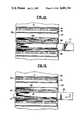
- FIG. 5is a cross-section of a specimen tray in accordance with this invention comprising a tray container as in FIG. 3 and a cover member as in FIG. 5.
- FIG. 6is a cross-section of a cover member of FIG. 5 taken normal to the direction of the cross-section in FIG. 5.
- FIG. 7is a schematic perspective view of the carousel and scanning assembly in accordance with this invention.
- FIGS. 8A-8Bare exploded views of the carousel and scanning assembly of this invention.
- FIGS. 9A-9Bare more detailed exploded views of the scanning system in accordance with this invention.
- FIG. 10is a partial perspective view illustrating operation of the tray moving system of this invention.
- FIG. 11is a partial side view in partial cross-section, illustrating the operation of the tray moving system of this invention.
- FIG. 12is a partial side view as in FIG. 11 at a later stage in the tray moving operation.
- FIG. 13is a partial side view as in FIG. 11 at a still later stage in the tray moving operation.
- FIG. 14is a partial side view as in FIG. 11 at a still later stage of the tray moving operation.
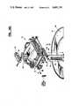
- FIG. 15is a perspective view of the dispenser systems.
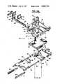
- FIG. 16is an exploded view of the dispenser system of this invention.
- an automatic specimen analyzing system 10is shown schematically.
- the system 10is adapted to analyze biologic specimens which have been selectively treated as desired.
- the specimensare arranged in specimen trays wherein each tray contains a plurality of the specimens.
- the system 10is adapted to automatically carry out, after the operator loads the specimen trays into the system 10, operations such as addition of reagents, incubation and the analysis.
- the specimen traysare loaded by the operator into a plurality of specimen tray supporting towers 11.
- the exact number of towers utilized in the systemmay be set as desired. However, the system is particularly adapted for use with a plurality of such towers 11.
- a work station 12is arranged in association with the tray towers 11 for selectively treating or analyzing the specimens in the trays supported by the towers 11.
- a selectively operable tray moving means 13is supported at the work station and serves to remove a specimen tray from the tray support tower and move it to the work station 12. The tray moving means 13 also serves to reinsert the tray into the tray supporting tower 11.
- a reagent delivery system 14includes a remote dispensing head 15 connected thereto and supported by the work station 12. The reagent delivery system 14 is selectively operable to administer a desired amount of at least one reagent to desired ones of the specimens in the tray through the remote dispensing head 15.
- a housing Hpreferably surrounds and encloses the environmentally sensitive elements of the automatic scanning analyzing system 10. Those elements include the tray support towers 11, the work station, the tray moving means 13, the reagent delivery means 14 and the remote dispensing means 15. Although these components can be used in a controlled environmental room without a housing, it is intended that the automatic specimen analyzing 10 of this invention includes such a housing for controlling temperature and humidity to provide proper incubation of the specimen.
- the environmental control system Eis connected to the housing H for controlling the temperature and humidity within the housing.
- the environmental control systemcomprises conventional means for controlling the humidity and temperature of the atmosphere within the housing H. While it is preferred for the housing H to enclose both the work stations and tray tower area and the remote dispensing area, if desired, the housing may enclose only the work station and tray tower area.
- the housingis provided with one or more access doors (not shown) to enable the operator to remove tray tower 11 from the analyzing system 10.
- the housingmay be made removable from the system entirely.
- the control system 16may be built into the housing and the housing H may include an indicator panel such as LED panel D. If desired, vaiours other gages and indicators can be mounted to the housing H.
- the work station 12also includes an analyzing means for determining at least one optical property of desired ones of the specimens in the tray.
- a control means 16is adapted to sequentially actuate the tray moving means 13 so that each of the trays are at least sequentially moved to the work station 12 for administration of the reagent by the reagent delivery system 14, then return to the tray support tower 11 and held there for a desired incubation time. Thereafter, the control means again causes the tray to be removed from the tray tower 11 and returned to the work station for analysis. The control means then causes the tray moving means to return the tray to the tray support tower 11 from which it can be removed by the operator for storage or disposal.
- the specimen tray assembly 17comprises an assembly which is adapted for use in the automatic system 10 for analyzing the specimens. Each tray assembly 17 is adapted to contain a plurality of separate specimens.
- the tray assembly 17is comprised of a container tray 18 having a plurality of microcuvettes 19 arranged in a spaced apart grid-like pattern.
- the container tray 18is best shown in FIG. 3 and corresponds to the MicroScan specimen panels as described in the background of this application.
- a cover member 20is adapted to seat over a top surface 21 of the container tray 18. The cover member 20 is clearly illustrated by reference to the aforenoted FIGS. 2, 4 and 5.
- the cover member 20includes tab portions 22 and 23 which extend outwardly in the plane of the cover members 20 from first and opposing edges 24 and 25 of the member.
- the tab portions 22 and 23are adapted, when the tray assembly 17 is inserted in the tray tower 11, to control the movement of the cover member 20 so that the container tray 18 can be readily removed from the tray tower 11 without the cover member.
- the cover memberis left in the tray tower so that the aforenoted operations of reagent additions or analysis can be readily carried out on the specimens in the container tray 18.
- the cover memberalso includes means for automatically centering the container tray relative to the cover member 20 to provide proper seating of the cover member on the container tray.
- the centering meanspreferably comprises a recess 26 in a bottom face 27 of the cover member 20 having a first peripheral wall 28.
- the first peripheral wall 28is adapted to seat about a second peripheral wall 29 of the container tray 18.
- the centering actionis provided by inclining the first peripheral wall 28 in the cover member inwardly of its periphery so that when the cover member 20 is urged against a misaligned container tray 18, the inclined first peripheral wall 28 acts on the second peripheral wall 29 of the container tray 18 to center and align the container tray with respect to the cover member.
- This centering feature of the tray assembly of the present inventionplays an important role with respect to the proper removal and reinsertion of the container tray 18 into the tray tower 11. This function will be described in greater detail hereinafter. Proper seating of the cover member 20 over the container tray 18 is important in order to insure that there is no undue evaporation of the contents of the cuvettes 19 in the container tray 18.
- the cover member 20preferably includes stiffening ribs 30 arranged as shown generally parallel to one another along a top face 31 of the cover member 20 and extending longitudinally between the respective tab portions 22 and 23.
- stiffening ribs 30are utilized in order to strengthen the cover member so that it can be resiliently urged against the container tray 18 to provide effective sealing against evaporation as will be described in greater detail hereinafter.
- the stiffening ribs 30therefore prevent bowing of the cover member 20. It is preferred to avoid such bowing of the cover member 20 in order to reduce evaporation and prevent interference with the container tray 18 as it is removed from the tray tower 11.
- each container tray 18includes ninety-six cuvettes or wells 19. Further, each container trayy 18, as shown in FIG. 3, can be recognized and identified by a bar code 32 which is provided on a side wall 33 of the container tray which will face the remote dispensing head 15. The bar code is added to the container tray 18 at the time of placing particular samples or specimens in the tray into the control system 16, and have the information associated with each tray represented thereon.
- the control systempreferably comprises a programmable computer which can print out the desired bar code at the time the information is in the system.
- tray support tower 11is adapted to support a plurality of tray assemblies 17.
- the exact number of tray assemblies 17may be set as described.
- Each tray tower 11is readily removable from the automatic specimen analyzing system 10 by loosening tie down bolts 34. This allows the tray tower 11 to be releasably connected to the automatic specimen analyzing system.
- Each tray assembly 17rests upon a shelf 35 which is slidingly supported so that it is removable in a first slot 36 in each of a first sidewall 37 and a second side wall 38 of the tray tower.
- the slots 36extend in a spaced apart, generally parallel, manner from a first open face 39 in the plane of the drawing to a second open face (not shown) behind the first open face 39.
- the slotsare closed at an end adjacent one of the open faces as will be described in greater detail hereinafter.
- Each of the shelves 35is removably supported in the first slots in each of the first and second side walls 37 and 38 to provide a spaced apart parallel and overlapping array of shelves 35 with the spaces between the shelves being adapted to receive the specimen tray assemblies 17.
- a corresponding plurality of second slots 40 in each of the first and second side walls 37 and 38extend in a spaced apart, generally parallel, manner from the first open face 39 to the second face (not shown).
- the second slotsare closed at an end adjacent one of the open faces which is selected to be the same faces as for the first slots 36.
- the second slots 40are adapted to receive the cover members 20 and to provide support for movement of the cover member 20 upwardly or downwardly within the width of the slot W.
- the width Wis selected to permit the cover member 20 to move widthwise of the slot as will be described in greater detail hereinafter.
- selectively operable means 41are provided at one of the open faces 39 of at least one side wall 37 for partially blocking the open face to prevent the tray assemblies 17 loaded in the tray tower from being pushed out of the opening in that face.
- the selectively operable means 41preferably comprises a multi-tabbed member 42 which is slidingly mounted on an edge of the side wall 37 by any suitable means (not shown). The tab member may be moved up and down so that the tray assembly 17 can be inserted or removed from the tower 11 or locked in place.
- the tabs 43 of the member 42serve to interfere with the cover member 20 when it is desired to lock the tray assembly 17 in place or to allow free passage of the cover member when the member 42 is moved upwardly out of blocking position. This movement may be accomplished manually by operator intervention or automatically through the use of a suitable solenoid 44 which is controlled by the programmable control system 16.
- the tie-down bolts 34are supported by the respective side walls 37 and 38 of the tower 11 and these, with a top portion 45 and bottom portion 46, comprise a tray tower frame.
- the tie-down bolts 34are adapted to screw into a tray tower moving carousel 47 as illustrated in FIG. 1.
- the specimen tray assemblies 17are removed from the tower.
- the shelves 35can also be removed from the tower and sterilized if desired.
- the tower itselfwhich comprises essentially the frame comprising top and bottom portions 45 and 46 and side walls 37 and 38, can then be sterilized also.
- FIGS. 7-9further details of the automatic specimen analyzing system 10 will be provided.
- these figuresshow the various apparatus for moving the tray towers 11 selectively into operative position with respect to the work station, the various elements of the tray assembly moving system and the work station itself.
- the carousel 47comprises a donut-shaped plate which surrounds the work station 12.
- Holes 48are provided in the top surface of the carousel 47. These holes are tapped so that the tie down bolts 34 of a respective tray tower 11 can be screwed therein in order to mount the tray tower to the carousel 47.
- the tray towersare not shown in FIGS. 8 and 9 in order to better illustrate the other aspects of the automatic specimen analyzing system 10.
- a carousel drive pulley 49is driven by means of a cogged belt 50 arranged about the drive pulley 49 and a cogged pulley 51.
- a stepping motor 52drives the cogged pulley 51 via a stepped-down cogged pulley and belt arrangement 53.
- the actuation of the stepping motoris controlled by the control system 16 and serves to rotate the carousel 47 to position a desired tray tower in operative association with the work station 12.
- the carousel 47is rotatably supported on a base frame 54 by means of V-track bearings 55. If desired, however, any appropriate means for rotatably supporting the carousel 47 could be employed.
- any desired drive arrangementcould be employed which is adapted to selectively position a desired one of the tray towers in operative association with the work station 12.
- a pair of vertical shafts 56support the work station 12 for vertical movement up and down along the shaft 56 axes.
- the shafts 56are supported in the frame 54 and at their opposing ends by a shaft mount 57.
- a work station carrier frame 58includes holes 59 with suitable bushings or bearings to provide for sliding movement of the carrier frame 58 along the shafts 56.
- a vertical axis drive screw 60is provided to drive the carrier frame 58, supporting the work station 12, up and down vertically along the shafts 56.
- the drive screw 60is journaled for rotation in the shaft mount 57 by means of ball bearings 61 and is also journaled for rotation in the frame 54 by means of bearings 62.
- the portions of the drive screw 60 which are journaled through rotationdo not include threads.
- the lower portion which is journaled in the base frame 54includes a drive cogged pulley 63 which is driven by means of a cogged belt 64 and pulley 65 mounted to the shaft of a stepping motor 66.
- the drive cogged pulley 63is of a larger diameter than the pulley 65 to provide a step-down drive arrangement.
- the stepper motor 66is controlled by the control system 16 to advance the work station 12 up and down as required to carry out the operations of the automatic specimen analyzing system which will be described hereinafter.
- the work station carrier frame 58 as previously describedis arranged for movement along the shafts 56 by means of linear bearings 67.
- the remote dispensing head 15is arranged for movement in a plane normal to the plane of movement provided by the shafts 56 and drive screw 60. This is accomplished by means of a guide rod 68 and dispensing head drive screw 69.
- the dispensing head 15is arranged for sliding movement on the rod 68 by means of oilless bearings 70.
- the drive screw 69is threaded through a hole 71 so as to provide the desired movement of the dispensing head 15 from side-to-side relative to the carrier frame 58.
- anti-backlash nuts 72 and 73are employed with respect to drive screws 60 and 69.
- the drive screw 69is journaled for rotation in end support blocks 74 and 75 which, in turn, are mounted to the carrier frame 58.
- the drive screwis journaled for rotation in the end blocks 74 and 75 by means of bearings 76 and 77.
- a cogged drive pulley 78is secured to one end of the drive screw 69.
- a stepper motor 79 mounted to the carrier frame 58drives the drive screw 69 by means of a cogged pulley 80 and belt 81.
- the cogged pulley 80is relatively larger in diameter than the drive pulley 78, thereby providing a step-up in the drive arrangement.
- a photodiode reader card assembly 82is supported on the underside of the carrier frame 58. This reader card assembly 82 serves in the analysis function of the work station to determine an optical property of the specimens in the tray assembly 17.
- An important element of the present automatic specimen analyzing system 10is a selectively operable tray moving system 13 which serves to remove a tray container 18 from the tray tower and move it into the work station for dispensing reagents into the specimens or their analysis, and for moving the tray container 18 back into the tray tower 11 as required.
- the tray moving system 13is supported by the carrier frame 58 and comprises a tray drive mount 83 which is secured to the carrier frame 58.
- the mount 83supports therein two parallel spaced-apart helical drive screws 84 which are journaled for rotation in the mount by means of bearings 85.
- the tray drive mount 83is located at one end of drive screws 84.
- a moving carriage or tray pick-up body 86is drivingly supported about the drive screws 84 by means of anti-backlash nut assemblies 87.
- the carriage 86supports two parallel spaced apart tray pick-up tines 88 and 89.
- drive pulleys 90are mounted which are driven by means of a cogged belt 91 through cogged pulley 92 which, in turn, is driven by stepper motor 93.
- the stepper motor 93is controlled by the control system 16 so as to advance or retract the tines 88 and 89 to respectively move a container tray 18 to and fro in a plane normal to the plane of movement of the carrier frame 58 and in a direction normal to the direction of movement of the remote dispensing head 15.
- the specimen analyzing system or scanning system 94 and 82comprising a tray block 95, an aperture plate 96, fiber bundle block 97 and photodiode reader card 82.
- the specimen analyzing system 94 and 82is essentially the same as that employed commercially in the MicroScan system described in the background of this application.
- the tray block 95, the aperture plate 96 and the fiber bundle block 97are arranged for movement vertically to and fro in the same direction as the carrier frame 58, however, in respect to the carrier frame 58.
- the aforenoted elementsare mounted to an optics block frame 98 via optics mounts 99.
- the tray block 95, the fiber bundle block 97 and the aperture 96are arranged for vertical movement on the optics block frame 98 by means of gear racks 100 which are spring-loaded against mounts 99.
- Mounts 99are located by two tooling balls and one locating button through three position posts. The three position posts are bolted to frame 98.
- Gear racks 100are slidingly supported in holes 101 in the optics block frame 98.
- Shafts 102are journaled for rotation in the frame 98 by means of bearings 103.
- Drive gears 104, in respective alignment with the gear racks 100,are supported on shafts 102 whose axes are arranged normal to the direction of movement of the gear rack 100.
- Cogged pulleys 105are supported at one end of the shafts 102 to provide drive to the shafts.
- the pulleys 105are driven by means of a stepper motor 106 and a cogged belt 107.
- the stepper motor 106is controlled by the control system 16 to provide clockwise or counterclockwise rotation of the shafts 102 in order to advance the gear racks 100 up or down and thereby advance the specimen analyzing system 94 up and down into and out of engagement with the bottom of a respective container tray 18 arranged at the work station 12.
- the tray towers 11comprise generally rectangular frames having a plurality of tray support shelves 35 removably supported therein.
- tower 11preferably, also includes means 108 for biasing the cover member 20 against the container tray 18 when they are positioned in the tower.
- the biasing means 108 and the operation of the tray moving system 13 and work station 12will now be illustrated by considering FIGS. 10-14.
- the tray tower 11includes side wall 37 having respective slots 36 and 40 ae previously described.
- a tray shelf 35is supported in the slot 36 whereas the cover member 20 is held captive by the tray tower second slot 40. It is held captive because the second slot 40 is closed at its end at open space 109. Similarly, the tray shelf 35 is captured by the closed end of the slot 36 at the open space 109.
- the tray tines 88 and 89include at their leading edges an inclined surface 110 which serves to engage the tab portions 22 or 23 to raise the cover member 20 off of the container tray 18 as the tines proceed into the tray tower by means of the drive imparted by stepper motor 93.
- a resilient biasing meansas shown in FIG.
- the vertical drive stepping motor 66is actuated to slightly raise the tines 88 and 89. This causes the tray cover 20 to be fully lifted off the container tray 18 and held in that position by the tray tine 88 and the opposing tray tine 89 not shown. This also serves to capture the container tray 18 in a recess 112 in the lower edge of the tines 88 and 89.
- the spring 108is now fully compressed. The slight vertical jog in the direction of arrow 113 is all that is necessary in order to capture the container tray 18 in the recess or pocket 112.
- the container trayis then withdrawn from the tray tower 11 by movement of the tines 88 and 89 in the direction of arrow 114 as shown in FIG. 14.
- the biasing spring 108Upon withdrawal of the container tray 18 from the tray tower 11, the biasing spring 108 returns the tray cover 20 to its normal position at the bottom of the second slot 40.
- the tray cover member 20does not follow the tines 88 and 89 out of the tray tower because of the closed end 109 of the second slot 40 which captures the tab portion of the tray cover member 20.
- the operationis reversed.
- tray cover member 20is raised up to permit the tray container 18 to enter.
- the stepper motor 66is jogged to move the tines vertically, downwardly, to release the tray container.
- the tinesare then withdrawn from the tray tower.
- the work stationcan then be advanced up or down to remove another tray from the tray tower.
- the specimen tray assembly 17is inserted in the tray tower 11 by the operator.
- the computer controller 16controls the actuation of the respective stepper motors previously described to withdraw desired tray assemblies 17 one at a time from a tray tower and transport them to the work station 12.
- a tray assembly 17is withdrawn from the tray tower, it is intended to dispense suitable reagents into the specimens in the tray container.
- This reagent dispensing processis accomplished by utilizing the respective X axis and Y axis movements achievable through the use of the tray moving system and the remote dispense head moving system.
- X movementcan be achieved by appropriately controlling stepper motor 93 to stepwise advance the tray container supported in the tines 88 and 89 under the dispensing head 15.
- Y movementis achieved by stepwise advancing the dispensing head from side-to-side of the carrier frame 58 under the actuation of stepper motor 79.
- the computer controller 16controls the respective actuations of the stepper motors to move the dispensing head to the desired cuvette 19 in the tray container 18 wherein a desired reagent is then metered therein.
- the dispensing head 15also includes a reader means R for reading the bar code 32 on the side 29 of the container tray 18. This is achieved by scanning the dispensing head 15 laterally across the bar reading means R.
- the reading means Rcomprises a sensor on the remote dispensing head for reading the bar code and is appropriately connected to the control system 16 to identify the sample being analyzed.
- the stepper motor 93is energized to advance the tines in a direction to reinsert the container tray 18 back into its respective slot in the tray tower 11 as described by reference to FIGS. 10-14.
- the computer controller 16then allows the inoculated samples with added reagents to incubate a desired amount of time after which the container tray 18 is again removed from the tower by repeating the sequence described by reference to FIGS. 10-14 and withdrawn to the work station 12.
- the analysisis carried out in a manner similar to that described for the MicroScan system in the background of this application.
- the tray block, aperture plate and optics block frameare moved into engagement with the bottom of the container tray 18 by means of actuating stepper motor 106.
- the tray blockis lowered by actuation of stepper motor 106 and the tray tines again return the tray container to the tray tower.
- the tray containermay be removed for storage or disposal as desired. In the alternative, it may be retained in the tray tower for an additional incubation period if so desired and the analyzing operation just described repeated following the incubation period.
- the tray cover member 20includes a recess 26 defining an inclined peripheral wall 28 which serves to center the container tray relative to the cover member. This action is achieved as shown by reference to FIGS. 10-14 under the influence of the biasing spring 108. If the tray container 18 should be reinserted in the tower 11 in slight misalignment from the cover member 20, then the cover member 20 can properly align it. This is possible since as the cover member 20 is engaged to the container tray 18 as the tines 88 and 89 are withdrawn, the inclined surface 28 serves to move the container tray relative to the cover member which is held from moving by the sidewalls in order to center the container tray and provide good sealing engagement between the cover member and the container tray.
- the incubation in the apparatus of this inventionis preferably carried out at about 37 degrees C, plus or minus 3 degrees. Since different tests require different incubation times, the computer controller 16 is set up so that each tray assembly 17 will be read based upon the tests which are desired for the specimens in that respective container tray 18.
- the apparatus 10 of this inventionis designed to read trays which have differing tests as the analysis functions, reagent dispensing functions and incubation periods are software determined. It is possible with the apparatus 10 of this invention to do kinetic readings as the various readings can be taken over a period of time thereby providing rate of growth studies in any particular cuvette 19.
- the reader assembly for analysisincludes a light source assembly comprising ninety-six fiber-optic lines from a light source. Each fiber-optic line is provided under each well in the tray. Over the tray, an aperture plate, or merely the light sensor, is used. The light is provided by a light source which is separated from the end of the fiber-optic bundle by an appropriate color wheel which provides filtering of the light due to various tests. Preferably, the color wheel includes nine colors, although normally only seven colors are read.
- the color wheel and light source assemblyas previously described, is essentially of the type previously employed with the autoSCAN system described in the background of this application. All seven readings are taken for each cuvette 19 and the associated software of the controller 16 throws out any unnecessary readings for each well. After a particular tray 18 has been read to completion, a light emitting diode D on the housing H will either be lighted or turned off to indicate that the tray has been analyzed and can be removed or replaced with another tray.
- the reagent delivery system 14comprises a plurality of reagent supply containers 115 arranged remotely from the work station 12 and means for selectively dispensing a desired amount of a reagent from a corresponding one of the reagent supply containers 115.
- a suitable conduit 117as shown in FIG. 1, connects each respective container 115 to a respective dispensing hole 118 in the dispensing head 15 shown in FIG. 9. Accordingly, there are as many conduits 117 and dispensing holes 118 employed as their are containers 115 mounted in the delivery system 14.
- the selective dispensing meanscomprises a dispensing station 116 in which the reagent containers 115 are arranged for movement past the dispensing station.
- Metering meansare provided at the dispensing station for controlling the amount of reagent dispensed from the reagent container 115 selected.
- the reagent containers 115comprise syringes comprising a container body 120 and plunger 121.
- a suitable syringe nozzle 122is used to connect the syringe 115 to the conduit 117.
- the carousel 123is mounted to shaft 124 which is journaled for rotation in a support base 125 by means of bearings 126.
- a stepping motor (not shown) in the base 125is drivingly connected to the shaft 124 and, under the influence of control system 16, stepwise advances the carousel 123 to position a desired one of the containers 115 at the dispensing station 116.
- the control system 16not only coordinates the movement of a desired one of the reagent containers to the dispensing station 116, but also controls the amount of reagent metered therefrom at the dispensing station in correspondence with the specimen arranged to receive the reagent.
- the syringes 115are releasably supported in carousel 123. This is achieved by providing a dispenser body housing support collar 127 about shaft 124 and a dispenser body housing 128 fitted over the collar 127. The carousel 123 is then supported on the end of shaft 124.
- a movable syringe mounting block 129is arranged to support the syringe by engaging a flange 130 of the syringe container body 120 from below.
- the mounting block 129is mounted on two dowel pins 131 arranged parallel to one another and arranged for sliding movement in holes 132 in the dispenser body housing 128.
- a syringe release shaft 133is also slidingly mounted in housing 128 so as to be spring biased by a spring 134 in an upward direction. The lower end of the shaft 133 is secured to mounting block 129.
- the carousel 123includes a series of slots 135 about its periphery through which the nozzle 122 of the syringe can pass, however, the shoulder 136 of the syringe abuts against the carousel plate from below. Therefore, in operation, to insert the syringe in the carousel assembly, the shaft 133 is depressed to lower the mounting block 129. The syringe 115 is then inserted so that the nozzle 122 protrudes through a slot 135 and the shaft 133 is then released so that under spring biasing, the block 129 engages the flange 130 to securely mount the syringe in the carousel assembly by spring biasing it between the mounting block 129 and the carousel plate 123.
- the carousel plate 123can include any desired number of syringes.
- a metering means 119is arranged at the dispensing station 116 which itself is positioned tangentially of the carousel 123.
- the metering means 119comprises an anvil 137 arranged for movement longitudinally of the desired one of the syringes at the dispensing station 116.
- the anvilis supported on a movable carriage 138.
- the carriageis arranged for movement in a sliding fashion along vertical shafts 139 which are supported at one end in the base 125 and at an opposing end in a frame secured to the base and comprising side bars 140 and top bar 141.
- Sleeve or linear bearingsare used to mount the carriage 138 to the shafts 139.
- a drive screw 142is journaled for rotation in the top bar 141 and extends through the base 125 wherein it is also journaled for rotation.
- the drive screwis drivingly connected to a stepping motor (not shown) which serves, by virtue of the driving connection between the drive screw and the carriage 138, to move the carriage 138 and the anvil 137 to and fro in a vertical direction; namely, vertically upwardly or downwardly as controlled by the control system.
- the control system 16controls the stepping motor connected to the drive screw 142, to drive the anvil 138 between respective positions. These comprise a first home position wherein it does not engage the syringe at all, a second dispense start position wherein it first engages the plunger 121 and a third finish position wherein it pushes the plunger into the body 120 to dispense the desired amount of reagent.
- the control system 16coordinates the movement of the carousel 123 to position the desired one of the syringes at the dispensing station and also controls via the stepping motor (not shown), the movement of the anvil 138 between its respective positions to dispense the desired amount of reagent.
- the control system 16includes a position sensor 143 for sensing the first engagement between the anvil and the plunger 121 and for causing responsive thereto the anvil to move to its third position.
- the carousel plate 123is adapted to rotate just under 360 degrees in either direction in aligning the reagent containers relative to the dispensing station.
- Each syringe positionis coded as well as the home position.
- the sensorIn searching for a particular syringe, the sensor is activated by the slots 135 and the computer can identify which syringe is at the dispensing station. If a particular syringe is not placed at the dispensing station before the sensor reaches the home slot the carousel is reversed in direction until it finds the particular syringe.
- the apparatus in accordance with this inventionis adapted to load and unload a tray container 18 from a tray tower 11 in approximately seven seconds, and a similar amount of time is required to analyze the specimens in the tray.
- the apparatusin addition to the position sensor 143 can include a number of other sensing and encoding devices for enabling the control system to control the operation as previously described. For example, encoders are used on the X and Y axes drives during the dispensing operation. Various optical interrupter type sensors are employed for detecting the container tray edge, the tine home position, the dispenser head home position, etc.
- roller bearings Bsupported by frame 98 against which the tines 88 and 89 ride when extending to take the tray from the tray tower 11. This helps to improve the stability of the tray moving system.
- the control system 16has not been described in detail but preferably comprises a programmable computer controller as are well known in the art. It is believed to be well within the skill of the art to program such a device to perform the desired sequences as described.
Landscapes
- Physics & Mathematics (AREA)
- Health & Medical Sciences (AREA)
- Life Sciences & Earth Sciences (AREA)
- Chemical & Material Sciences (AREA)
- Analytical Chemistry (AREA)
- Biochemistry (AREA)
- General Health & Medical Sciences (AREA)
- General Physics & Mathematics (AREA)
- Immunology (AREA)
- Pathology (AREA)
- Automatic Analysis And Handling Materials Therefor (AREA)
Abstract
Description
Claims (9)
Priority Applications (1)
| Application Number | Priority Date | Filing Date | Title |
|---|---|---|---|
| US06/943,820US4681741A (en) | 1985-07-01 | 1986-12-17 | Reagent dispenser for an analyzing system |
Applications Claiming Priority (2)
| Application Number | Priority Date | Filing Date | Title |
|---|---|---|---|
| US75079185A | 1985-07-01 | 1985-07-01 | |
| US06/943,820US4681741A (en) | 1985-07-01 | 1986-12-17 | Reagent dispenser for an analyzing system |
Related Parent Applications (1)
| Application Number | Title | Priority Date | Filing Date |
|---|---|---|---|
| US75079185AContinuation | 1985-07-01 | 1985-07-01 |
Publications (1)
| Publication Number | Publication Date |
|---|---|
| US4681741Atrue US4681741A (en) | 1987-07-21 |
Family
ID=27115321
Family Applications (1)
| Application Number | Title | Priority Date | Filing Date |
|---|---|---|---|
| US06/943,820Expired - Fee RelatedUS4681741A (en) | 1985-07-01 | 1986-12-17 | Reagent dispenser for an analyzing system |
Country Status (1)
| Country | Link |
|---|---|
| US (1) | US4681741A (en) |
Cited By (61)
| Publication number | Priority date | Publication date | Assignee | Title |
|---|---|---|---|---|
| US4877745A (en)* | 1986-11-17 | 1989-10-31 | Abbott Laboratories | Apparatus and process for reagent fluid dispensing and printing |
| US4967938A (en)* | 1989-07-17 | 1990-11-06 | Fluid Management Limited Partnership | Paint dispensing apparatus |
| US4976924A (en)* | 1988-04-22 | 1990-12-11 | Her Majesty The Queen In Right Of Canada, As Represented By The Minister Of National Defence | Automated thermal desorption unit |
| US5065905A (en)* | 1990-05-23 | 1991-11-19 | Xerox Corporation | Hardware delivery system |
| US5089229A (en) | 1989-11-22 | 1992-02-18 | Vettest S.A. | Chemical analyzer |
| US5119973A (en)* | 1990-12-14 | 1992-06-09 | Fluid Management Limited Partnership | Automated dispensing apparatus |
| US5150821A (en)* | 1989-04-07 | 1992-09-29 | Tosoh Corporation | Apparatus for separate injection of reagent |
| US5250262A (en) | 1989-11-22 | 1993-10-05 | Vettest S.A. | Chemical analyzer |
| US5518686A (en)* | 1991-10-31 | 1996-05-21 | Dade Microscan Inc. | Specimen processing and analyzing systems with associated fluid dispensing apparatus |
| US5599501A (en)* | 1994-11-10 | 1997-02-04 | Ciba Corning Diagnostics Corp. | Incubation chamber |
| US5609822A (en)* | 1995-07-07 | 1997-03-11 | Ciba Corning Diagnostics Corp. | Reagent handling system and reagent pack for use therein |
| US5795784A (en) | 1996-09-19 | 1998-08-18 | Abbott Laboratories | Method of performing a process for determining an item of interest in a sample |
| US5856194A (en) | 1996-09-19 | 1999-01-05 | Abbott Laboratories | Method for determination of item of interest in a sample |
| US5927547A (en)* | 1996-05-31 | 1999-07-27 | Packard Instrument Company | System for dispensing microvolume quantities of liquids |
| US6066300A (en)* | 1995-07-07 | 2000-05-23 | Bayer Corporation | Reagent handling system and configurable vial carrier for use therein |
| US6203759B1 (en) | 1996-05-31 | 2001-03-20 | Packard Instrument Company | Microvolume liquid handling system |
| US6269978B1 (en)* | 1999-07-16 | 2001-08-07 | Italtinto S.R.L. | Dispensing and dosing machine for dyestuffs |
| US20020085959A1 (en)* | 1991-03-04 | 2002-07-04 | Glen Carey | Cuvette for an automated analyzer |
| US20030032173A1 (en)* | 2001-08-08 | 2003-02-13 | Dade Behring Inc. | Reagent container and canister for use in an automated microbiological analyzer |
| US6521187B1 (en) | 1996-05-31 | 2003-02-18 | Packard Instrument Company | Dispensing liquid drops onto porous brittle substrates |
| US6537817B1 (en) | 1993-05-31 | 2003-03-25 | Packard Instrument Company | Piezoelectric-drop-on-demand technology |
| US6573088B2 (en) | 2001-08-08 | 2003-06-03 | Dade Microscan Inc. | Automated random access microbiological analyzer |
| US6632654B1 (en) | 2001-08-08 | 2003-10-14 | Dade Microscan Inc. | Canister for inventorying susceptability test devices in an automated microbiological analyzer |
| US20030194349A1 (en)* | 1991-03-04 | 2003-10-16 | Glen Carey | Fluid handling apparatus for an automated analyzer |
| US20030203493A1 (en)* | 2002-04-26 | 2003-10-30 | Ventana Medical Systems, Inc. | Automated molecular pathology apparatus having fixed slide platforms |
| US6776966B2 (en) | 2001-08-08 | 2004-08-17 | Dade Behring Inc. | Canister for inventorying identification test devices in an automated microbiological analyzer |
| US20040185552A1 (en)* | 2003-03-20 | 2004-09-23 | Griner Christopher Dallas | Microbiological analyzer using colorimetric means for biochemical color and growth determinations |
| US6827901B2 (en) | 1990-03-02 | 2004-12-07 | Ventana Medical Systems, Inc. | Automated biological reaction apparatus |
| US20050035143A1 (en)* | 2003-08-15 | 2005-02-17 | Peter Massaro | Method and apparatus for handling small volume fluid samples |
| US20050036911A1 (en)* | 2003-08-12 | 2005-02-17 | Sellers James M. | Slide cartridge and reagent test slides for use with a chemical analyzer, and chemical analyzer for same |
| US20050095665A1 (en)* | 1999-04-29 | 2005-05-05 | Dade Behring, Inc. | Combined rapid susceptibility assay and microorganism identification system |
| US20060085140A1 (en)* | 2002-12-20 | 2006-04-20 | Gordon Feingold | Information notification sample processing system and methods of biological slide processing |
| US20060169718A1 (en)* | 2004-02-27 | 2006-08-03 | Eric Buining | Fluid and hair-dye dispensers |
| US20060231578A1 (en)* | 2004-02-27 | 2006-10-19 | Lenteq, Lp | Fluid and hair-dye dispensers |
| AU2005202093A1 (en)* | 2005-05-17 | 2006-12-07 | Tera Autotech Corporation | Fluid storage and injection mechanism for simultaneous analyzer |
| US7270785B1 (en) | 2001-11-02 | 2007-09-18 | Ventana Medical Systems, Inc. | Automated molecular pathology apparatus having fixed slide platforms |
| US7303725B2 (en) | 2002-04-15 | 2007-12-04 | Ventana Medical Systems, Inc. | Automated high volume slide staining system |
| US20070295113A1 (en)* | 2004-06-14 | 2007-12-27 | Parker-Hannifin Corporation | Robotic Handling System and Method with Independently Operable Detachable Tools |
| US20080156117A1 (en)* | 2005-01-28 | 2008-07-03 | Parker-Hannifin Corporation | Sampling Probe, Gripper and Interface For Laboratory Sample Management Systems |
| CN100413594C (en)* | 2003-06-04 | 2008-08-27 | 吉耐尔基因方案解决有限公司 | Biological material processing device |
| US7468161B2 (en) | 2002-04-15 | 2008-12-23 | Ventana Medical Systems, Inc. | Automated high volume slide processing system |
| US20080314412A1 (en)* | 2005-12-05 | 2008-12-25 | Grippo Paul M | Self-Cleaning Injection Port for Analytical Applications |
| US20090032065A1 (en)* | 2005-12-08 | 2009-02-05 | Bantz Daniel L | Syringe wash station for analytical applications |
| US20090235764A1 (en)* | 2008-01-25 | 2009-09-24 | Ganz Brian L | Automated machine for transferring solution from a source microwell plate to a destination microwell plate |
| US20100238968A1 (en)* | 2007-11-01 | 2010-09-23 | Ge Healthcare Bio-Sciences Corp. | Isothermal titration microcalorimeter apparatus and method of use |
| WO2011135583A3 (en)* | 2010-04-26 | 2012-01-26 | Span Biotronics Private Limited | Antibiotic disc dispensing devices |
| US20120018034A1 (en)* | 2009-03-30 | 2012-01-26 | Cps Color Equipment Spa Con Unico Socio | Delivery Device for Fluid Products and Relative Delivery Method |
| US20120073389A1 (en)* | 2010-07-02 | 2012-03-29 | Instrumentation Scientifique De Laboratoire | Method for injecting a sample being analyzed into the injection tube of a measurement cell, in particular of a densimeter |
| US20120214711A1 (en)* | 2009-01-24 | 2012-08-23 | Ganz Brian L | Automated machine for transferring solution from a source microwell plate to a destination microwell plate |
| US20130158704A1 (en)* | 2011-12-16 | 2013-06-20 | Randall L. Hughes | Method and apparatus for producing paint |
| US8585989B2 (en) | 2003-12-04 | 2013-11-19 | Idexx Laboratories, Inc. | Retaining clip for reagent test slides |
| US9116129B2 (en) | 2007-05-08 | 2015-08-25 | Idexx Laboratories, Inc. | Chemical analyzer |
| DE10222333B4 (en)* | 2002-05-18 | 2016-11-10 | Leica Biosystems Nussloch Gmbh | Device for collecting printed cassettes and / or printed slides for histological or cytological preparations |
| US9797916B2 (en) | 2014-01-10 | 2017-10-24 | Idexx Laboratories, Inc. | Chemical analyzer |
| EP3267962A4 (en)* | 2015-03-12 | 2018-10-03 | The Trustees Of The University Of Pennsylvania | System, method, and device for high-throughput, automated culturing of genetically modified organisms |
| US10184862B2 (en) | 2008-11-12 | 2019-01-22 | Ventana Medical Systems, Inc. | Methods and apparatuses for heating slides carrying specimens |
| US10794805B2 (en) | 2013-12-13 | 2020-10-06 | Ventana Medical Systems, Inc. | Automated histological processing of biological specimens and associated technology |
| US20210033629A1 (en)* | 2019-07-29 | 2021-02-04 | Waters Technologies Corporation | Interface module for robotic loading and unloading of a sample manager for liquid chromatography |
| US11249095B2 (en) | 2002-04-15 | 2022-02-15 | Ventana Medical Systems, Inc. | Automated high volume slide processing system |
| US11977091B2 (en) | 2020-07-10 | 2024-05-07 | Idexx Laboratories Inc. | Point-of-care medical diagnostic analyzer and devices, systems, and methods for medical diagnostic analysis of samples |
| US12332199B2 (en) | 2008-12-02 | 2025-06-17 | Malvern Panalytical Limited | Automatic isothermal titration microcalorimeter apparatus and method of use |
Citations (14)
| Publication number | Priority date | Publication date | Assignee | Title |
|---|---|---|---|---|
| US28801A (en)* | 1860-06-19 | Improvement in steam-plows | ||
| US3074597A (en)* | 1958-11-21 | 1963-01-22 | Microdot Inc | Pigment measuring and dispensing device |
| USRE28801E (en) | 1972-09-20 | 1976-05-04 | Akro-Medic Engineering, Inc. | Apparatus for evaluation of biological fluid |
| US3957583A (en)* | 1974-12-02 | 1976-05-18 | Mcdonnell Douglas Corporation | Apparatus and process for determining the susceptibility of microorganisms to antibiotics |
| US3973696A (en)* | 1975-07-23 | 1976-08-10 | Vpi Educational Foundation | Method and apparatus for automatically injecting the fluid contents of a plurality of pre-loaded syringes into a gas chromatograph or the like |
| US4096972A (en)* | 1976-02-06 | 1978-06-27 | Mettler Instrumente Ag | Apparatus for the selective delivery of portions of a fluid medium |
| US4116775A (en)* | 1976-05-03 | 1978-09-26 | Mcdonnell Douglas Corporation | Machine and process for reading cards containing medical specimens |
| US4116067A (en)* | 1977-09-06 | 1978-09-26 | Aerovironment Inc. | Fluid sampling devices |
| US4118280A (en)* | 1976-05-03 | 1978-10-03 | Mcdonnell Douglas Corporation | Automated microbial analyzer |
| US4448534A (en)* | 1978-03-30 | 1984-05-15 | American Hospital Corporation | Antibiotic susceptibility testing |
| GB2131168A (en)* | 1982-11-30 | 1984-06-13 | Japan Tectron Instr Corp | Automatic analysis apparatus |
| US4458544A (en)* | 1982-03-09 | 1984-07-10 | Mobil Oil Corporation | Sample supply system and the handling of samples |
| US4517160A (en)* | 1979-04-14 | 1985-05-14 | Olympus Optical Company Limited | Automatic analyzing apparatus |
| US4528159A (en)* | 1981-07-20 | 1985-07-09 | American Hospital Supply Corp. | Automated analysis instrument system |
- 1986
- 1986-12-17USUS06/943,820patent/US4681741A/ennot_activeExpired - Fee Related
Patent Citations (14)
| Publication number | Priority date | Publication date | Assignee | Title |
|---|---|---|---|---|
| US28801A (en)* | 1860-06-19 | Improvement in steam-plows | ||
| US3074597A (en)* | 1958-11-21 | 1963-01-22 | Microdot Inc | Pigment measuring and dispensing device |
| USRE28801E (en) | 1972-09-20 | 1976-05-04 | Akro-Medic Engineering, Inc. | Apparatus for evaluation of biological fluid |
| US3957583A (en)* | 1974-12-02 | 1976-05-18 | Mcdonnell Douglas Corporation | Apparatus and process for determining the susceptibility of microorganisms to antibiotics |
| US3973696A (en)* | 1975-07-23 | 1976-08-10 | Vpi Educational Foundation | Method and apparatus for automatically injecting the fluid contents of a plurality of pre-loaded syringes into a gas chromatograph or the like |
| US4096972A (en)* | 1976-02-06 | 1978-06-27 | Mettler Instrumente Ag | Apparatus for the selective delivery of portions of a fluid medium |
| US4116775A (en)* | 1976-05-03 | 1978-09-26 | Mcdonnell Douglas Corporation | Machine and process for reading cards containing medical specimens |
| US4118280A (en)* | 1976-05-03 | 1978-10-03 | Mcdonnell Douglas Corporation | Automated microbial analyzer |
| US4116067A (en)* | 1977-09-06 | 1978-09-26 | Aerovironment Inc. | Fluid sampling devices |
| US4448534A (en)* | 1978-03-30 | 1984-05-15 | American Hospital Corporation | Antibiotic susceptibility testing |
| US4517160A (en)* | 1979-04-14 | 1985-05-14 | Olympus Optical Company Limited | Automatic analyzing apparatus |
| US4528159A (en)* | 1981-07-20 | 1985-07-09 | American Hospital Supply Corp. | Automated analysis instrument system |
| US4458544A (en)* | 1982-03-09 | 1984-07-10 | Mobil Oil Corporation | Sample supply system and the handling of samples |
| GB2131168A (en)* | 1982-11-30 | 1984-06-13 | Japan Tectron Instr Corp | Automatic analysis apparatus |
Cited By (136)
| Publication number | Priority date | Publication date | Assignee | Title |
|---|---|---|---|---|
| US4877745A (en)* | 1986-11-17 | 1989-10-31 | Abbott Laboratories | Apparatus and process for reagent fluid dispensing and printing |
| US4976924A (en)* | 1988-04-22 | 1990-12-11 | Her Majesty The Queen In Right Of Canada, As Represented By The Minister Of National Defence | Automated thermal desorption unit |
| US5150821A (en)* | 1989-04-07 | 1992-09-29 | Tosoh Corporation | Apparatus for separate injection of reagent |
| US4967938A (en)* | 1989-07-17 | 1990-11-06 | Fluid Management Limited Partnership | Paint dispensing apparatus |
| US5336467A (en) | 1989-11-22 | 1994-08-09 | Vettest S.A. | Chemical analyzer |
| US5089229A (en) | 1989-11-22 | 1992-02-18 | Vettest S.A. | Chemical analyzer |
| US5250262A (en) | 1989-11-22 | 1993-10-05 | Vettest S.A. | Chemical analyzer |
| US6827901B2 (en) | 1990-03-02 | 2004-12-07 | Ventana Medical Systems, Inc. | Automated biological reaction apparatus |
| US20050153453A1 (en)* | 1990-03-02 | 2005-07-14 | Ventana Medical Systems, Inc. | Automated biological reaction apparatus |
| US6943029B2 (en) | 1990-03-02 | 2005-09-13 | Ventana Medical Systems, Inc. | Automated biological reaction apparatus |
| US7470541B2 (en) | 1990-03-02 | 2008-12-30 | Ventana Medical System, Inc. | Automated biological reaction apparatus |
| US5065905A (en)* | 1990-05-23 | 1991-11-19 | Xerox Corporation | Hardware delivery system |
| US5119973A (en)* | 1990-12-14 | 1992-06-09 | Fluid Management Limited Partnership | Automated dispensing apparatus |
| US20030194349A1 (en)* | 1991-03-04 | 2003-10-16 | Glen Carey | Fluid handling apparatus for an automated analyzer |
| US20020085959A1 (en)* | 1991-03-04 | 2002-07-04 | Glen Carey | Cuvette for an automated analyzer |
| US7182912B2 (en) | 1991-03-04 | 2007-02-27 | Bayer Corporation | Fluid handling apparatus for an automated analyzer |
| US5645800A (en)* | 1991-10-31 | 1997-07-08 | Dade Microscan Inc. | Specimen processing and analyzing systems with associated fluid dispensing apparatus |
| US5518686A (en)* | 1991-10-31 | 1996-05-21 | Dade Microscan Inc. | Specimen processing and analyzing systems with associated fluid dispensing apparatus |
| US6537817B1 (en) | 1993-05-31 | 2003-03-25 | Packard Instrument Company | Piezoelectric-drop-on-demand technology |
| US5827478A (en)* | 1994-11-10 | 1998-10-27 | Chiron Diagnostics Corporation | Incubation chamber |
| US5599501A (en)* | 1994-11-10 | 1997-02-04 | Ciba Corning Diagnostics Corp. | Incubation chamber |
| US6066300A (en)* | 1995-07-07 | 2000-05-23 | Bayer Corporation | Reagent handling system and configurable vial carrier for use therein |
| US5788928A (en)* | 1995-07-07 | 1998-08-04 | Chiron Diagnostics Corporation | Reagent handling system and reagent pack for use therein |
| US5609822A (en)* | 1995-07-07 | 1997-03-11 | Ciba Corning Diagnostics Corp. | Reagent handling system and reagent pack for use therein |
| US6521187B1 (en) | 1996-05-31 | 2003-02-18 | Packard Instrument Company | Dispensing liquid drops onto porous brittle substrates |
| US5927547A (en)* | 1996-05-31 | 1999-07-27 | Packard Instrument Company | System for dispensing microvolume quantities of liquids |
| US6422431B2 (en) | 1996-05-31 | 2002-07-23 | Packard Instrument Company, Inc. | Microvolume liquid handling system |
| US6079283A (en)* | 1996-05-31 | 2000-06-27 | Packard Instruments Comapny | Method for aspirating sample liquid into a dispenser tip and thereafter ejecting droplets therethrough |
| US6083762A (en)* | 1996-05-31 | 2000-07-04 | Packard Instruments Company | Microvolume liquid handling system |
| US6112605A (en)* | 1996-05-31 | 2000-09-05 | Packard Instrument Company | Method for dispensing and determining a microvolume of sample liquid |
| US6203759B1 (en) | 1996-05-31 | 2001-03-20 | Packard Instrument Company | Microvolume liquid handling system |
| US6592825B2 (en) | 1996-05-31 | 2003-07-15 | Packard Instrument Company, Inc. | Microvolume liquid handling system |
| US5795784A (en) | 1996-09-19 | 1998-08-18 | Abbott Laboratories | Method of performing a process for determining an item of interest in a sample |
| US5856194A (en) | 1996-09-19 | 1999-01-05 | Abbott Laboratories | Method for determination of item of interest in a sample |
| US6562298B1 (en) | 1996-09-19 | 2003-05-13 | Abbott Laboratories | Structure for determination of item of interest in a sample |
| US20050095665A1 (en)* | 1999-04-29 | 2005-05-05 | Dade Behring, Inc. | Combined rapid susceptibility assay and microorganism identification system |
| US8828680B2 (en) | 1999-04-29 | 2014-09-09 | Siemens Healthcare Diagnostics Inc. | Combined rapid susceptibility assay and microorganism identification system |
| US6269978B1 (en)* | 1999-07-16 | 2001-08-07 | Italtinto S.R.L. | Dispensing and dosing machine for dyestuffs |
| US6855540B2 (en) | 2001-08-08 | 2005-02-15 | Dade Behring Inc. | Reagent container and canister for use in an automated microbiological analyzer |
| US20030032173A1 (en)* | 2001-08-08 | 2003-02-13 | Dade Behring Inc. | Reagent container and canister for use in an automated microbiological analyzer |
| US6573088B2 (en) | 2001-08-08 | 2003-06-03 | Dade Microscan Inc. | Automated random access microbiological analyzer |
| US6632654B1 (en) | 2001-08-08 | 2003-10-14 | Dade Microscan Inc. | Canister for inventorying susceptability test devices in an automated microbiological analyzer |
| US6776966B2 (en) | 2001-08-08 | 2004-08-17 | Dade Behring Inc. | Canister for inventorying identification test devices in an automated microbiological analyzer |
| US7404927B2 (en) | 2001-11-02 | 2008-07-29 | Ventana Medical Systems, Inc. | Automated molecular pathology apparatus having fixed slide platforms |
| US7270785B1 (en) | 2001-11-02 | 2007-09-18 | Ventana Medical Systems, Inc. | Automated molecular pathology apparatus having fixed slide platforms |
| US11092611B2 (en) | 2002-04-15 | 2021-08-17 | Ventana Medical Systems, Inc. | Automated high volume slide processing system |
| US8048373B2 (en) | 2002-04-15 | 2011-11-01 | Ventana Medical Systems, Inc. | Automated high volume slide staining system |
| US8663991B2 (en) | 2002-04-15 | 2014-03-04 | Ventana Medical Systems, Inc. | Automated high volume slide processing system |
| US11249095B2 (en) | 2002-04-15 | 2022-02-15 | Ventana Medical Systems, Inc. | Automated high volume slide processing system |
| US10302665B2 (en) | 2002-04-15 | 2019-05-28 | Ventana Medical Systems, Inc. | Automated high volume slide processing system |
| US7468161B2 (en) | 2002-04-15 | 2008-12-23 | Ventana Medical Systems, Inc. | Automated high volume slide processing system |
| US9528918B2 (en) | 2002-04-15 | 2016-12-27 | Ventana Medical Systems, Inc. | Automated high volume slide processing system |
| US7303725B2 (en) | 2002-04-15 | 2007-12-04 | Ventana Medical Systems, Inc. | Automated high volume slide staining system |
| US20030203493A1 (en)* | 2002-04-26 | 2003-10-30 | Ventana Medical Systems, Inc. | Automated molecular pathology apparatus having fixed slide platforms |
| US7378055B2 (en) | 2002-04-26 | 2008-05-27 | Ventana Medical Systems, Inc. | Automated molecular pathology apparatus having fixed slide platforms |
| US20070086917A1 (en)* | 2002-04-26 | 2007-04-19 | Charles Lemme | Automated molecular pathology apparatus having fixed slide platforms |
| DE10222333B4 (en)* | 2002-05-18 | 2016-11-10 | Leica Biosystems Nussloch Gmbh | Device for collecting printed cassettes and / or printed slides for histological or cytological preparations |
| US7758809B2 (en) | 2002-12-20 | 2010-07-20 | Dako Cytomation Denmark A/S | Method and system for pretreatment of tissue slides |
| US8673642B2 (en) | 2002-12-20 | 2014-03-18 | Dako Denmark A/S | Enhanced scheduling sample processing system and methods of biological slide processing |
| US8663978B2 (en) | 2002-12-20 | 2014-03-04 | Dako Denmark A/S | Method and apparatus for automatic staining of tissue samples |
| US8529836B2 (en) | 2002-12-20 | 2013-09-10 | Dako Denmark A/S | Apparatus for automated processing biological samples |
| US20060085140A1 (en)* | 2002-12-20 | 2006-04-20 | Gordon Feingold | Information notification sample processing system and methods of biological slide processing |
| US9778273B2 (en) | 2002-12-20 | 2017-10-03 | Dako Denmark A/S | Isolated communication sample processing system and methods of biological slide processing |
| US7400983B2 (en) | 2002-12-20 | 2008-07-15 | Dako Denmark A/S | Information notification sample processing system and methods of biological slide processing |
| US8394635B2 (en) | 2002-12-20 | 2013-03-12 | Dako Denmark A/S | Enhanced scheduling sample processing system and methods of biological slide processing |
| US20060088928A1 (en)* | 2002-12-20 | 2006-04-27 | Dakocytomation Denmark A/S | Method and apparatus for automatic staining of tissue samples |
| US9229016B2 (en) | 2002-12-20 | 2016-01-05 | Dako Denmark A/S | Information notification sample processing system and methods of biological slide processing |
| US8386195B2 (en) | 2002-12-20 | 2013-02-26 | Dako Denmark A/S | Information notification sample processing system and methods of biological slide processing |
| US8298815B2 (en) | 2002-12-20 | 2012-10-30 | Dako Denmark A/S | Systems and methods of sample processing and temperature control |
| US8788217B2 (en) | 2002-12-20 | 2014-07-22 | Dako Denmark A/S | Information notification sample processing system and methods of biological slide processing |
| US10156580B2 (en) | 2002-12-20 | 2018-12-18 | Dako Denmark A/S | Information notification sample processing system and methods of biological slide processing |
| US8257968B2 (en) | 2002-12-20 | 2012-09-04 | Dako Denmark A/S | Method and apparatus for automatic staining of tissue samples |
| US7648678B2 (en) | 2002-12-20 | 2010-01-19 | Dako Denmark A/S | Method and system for pretreatment of tissue slides |
| US9599630B2 (en) | 2002-12-20 | 2017-03-21 | Dako Denmark A/S | Method and apparatus for automatic staining of tissue samples |
| US8969086B2 (en) | 2002-12-20 | 2015-03-03 | Dako Denmark A/S | Enhanced scheduling sample processing system and methods of biological slide processing |
| US8216512B2 (en) | 2002-12-20 | 2012-07-10 | Dako Denmark A/S | Apparatus for automated processing biological samples |
| US7937228B2 (en) | 2002-12-20 | 2011-05-03 | Dako Denmark A/S | Information notification sample processing system and methods of biological slide processing |
| US7960178B2 (en) | 2002-12-20 | 2011-06-14 | Dako Denmark A/S | Enhanced scheduling sample processing system and methods of biological slide processing |
| US8784735B2 (en) | 2002-12-20 | 2014-07-22 | Dako Denmark A/S | Apparatus for automated processing biological samples |
| US20040185552A1 (en)* | 2003-03-20 | 2004-09-23 | Griner Christopher Dallas | Microbiological analyzer using colorimetric means for biochemical color and growth determinations |
| US6872545B2 (en) | 2003-03-20 | 2005-03-29 | Dade Behring Inc. | Microbiological analyzer using colorimetric means for biochemical color and growth determinations |
| CN100413594C (en)* | 2003-06-04 | 2008-08-27 | 吉耐尔基因方案解决有限公司 | Biological material processing device |
| US8287823B2 (en) | 2003-08-12 | 2012-10-16 | Idexx Laboratories, Inc. | Slide cartridge and reagent test slides for use with a chemical analyzer, and chemical analyzer for same |
| US20050036911A1 (en)* | 2003-08-12 | 2005-02-17 | Sellers James M. | Slide cartridge and reagent test slides for use with a chemical analyzer, and chemical analyzer for same |
| US7273591B2 (en) | 2003-08-12 | 2007-09-25 | Idexx Laboratories, Inc. | Slide cartridge and reagent test slides for use with a chemical analyzer, and chemical analyzer for same |
| US7097070B2 (en) | 2003-08-15 | 2006-08-29 | Protedyne Corporation | Method and apparatus for handling small volume fluid samples |
| US20050035143A1 (en)* | 2003-08-15 | 2005-02-17 | Peter Massaro | Method and apparatus for handling small volume fluid samples |
| US8585989B2 (en) | 2003-12-04 | 2013-11-19 | Idexx Laboratories, Inc. | Retaining clip for reagent test slides |
| US20060231578A1 (en)* | 2004-02-27 | 2006-10-19 | Lenteq, Lp | Fluid and hair-dye dispensers |
| US7597217B2 (en) | 2004-02-27 | 2009-10-06 | Lenteq, Lp | Two disc valve pump assembly for a fluid dispenser |
| US20060261089A1 (en)* | 2004-02-27 | 2006-11-23 | Lenteq, Lp | Hair dye dispenser |
| US20060278663A1 (en)* | 2004-02-27 | 2006-12-14 | Lenteq, Lp | Valve actuator for a fluid dispenser |
| US20060283889A1 (en)* | 2004-02-27 | 2006-12-21 | Lenteq, Lp | Two disc valve pump assembly for a fluid dispenser |
| US7654416B2 (en) | 2004-02-27 | 2010-02-02 | Stibbe Management Bv | Fluid and hair-dye dispensers |
| US20060169718A1 (en)* | 2004-02-27 | 2006-08-03 | Eric Buining | Fluid and hair-dye dispensers |
| US7185789B2 (en) | 2004-02-27 | 2007-03-06 | Lenteq, Lp | Hair dye dispenser |
| US20070295113A1 (en)* | 2004-06-14 | 2007-12-27 | Parker-Hannifin Corporation | Robotic Handling System and Method with Independently Operable Detachable Tools |
| US8187535B2 (en) | 2004-06-14 | 2012-05-29 | Parker-Hannifin Corporation | Robotic handling system and method with independently operable detachable tools |
| US8057756B2 (en) | 2005-01-28 | 2011-11-15 | Parker-Hannifin Corporation | Sampling probe, gripper and interface for laboratory sample management systems |
| US20080156117A1 (en)* | 2005-01-28 | 2008-07-03 | Parker-Hannifin Corporation | Sampling Probe, Gripper and Interface For Laboratory Sample Management Systems |
| US10900982B2 (en) | 2005-04-27 | 2021-01-26 | Ventana Medical Systems, Inc. | Automated high volume slide processing system |
| US11815518B2 (en) | 2005-04-27 | 2023-11-14 | Ventana Medical Systems, Inc. | Automated high volume slide processing system |
| AU2005202093A1 (en)* | 2005-05-17 | 2006-12-07 | Tera Autotech Corporation | Fluid storage and injection mechanism for simultaneous analyzer |
| US20080314412A1 (en)* | 2005-12-05 | 2008-12-25 | Grippo Paul M | Self-Cleaning Injection Port for Analytical Applications |
| US20090032065A1 (en)* | 2005-12-08 | 2009-02-05 | Bantz Daniel L | Syringe wash station for analytical applications |
| US9116129B2 (en) | 2007-05-08 | 2015-08-25 | Idexx Laboratories, Inc. | Chemical analyzer |
| US9823109B2 (en) | 2007-05-08 | 2017-11-21 | Idexx Laboratories, Inc. | Chemical analyzer |
| US8449175B2 (en)* | 2007-11-01 | 2013-05-28 | Ge Healthcare Bio-Sciences Corp. | Isothermal titration microcalorimeter apparatus and method of use |
| US8827549B2 (en)* | 2007-11-01 | 2014-09-09 | Ge Healthcare Bio-Sciences Corp. | Isothermal titration microcalorimeter apparatus and method of use |
| US20100238968A1 (en)* | 2007-11-01 | 2010-09-23 | Ge Healthcare Bio-Sciences Corp. | Isothermal titration microcalorimeter apparatus and method of use |
| US20140219311A1 (en)* | 2007-11-01 | 2014-08-07 | Ge Healthcare Bio-Sciences Corp. | Isothermal titration microcalorimeter apparatus and method of use |
| US20090235764A1 (en)* | 2008-01-25 | 2009-09-24 | Ganz Brian L | Automated machine for transferring solution from a source microwell plate to a destination microwell plate |
| US8038940B2 (en)* | 2008-01-25 | 2011-10-18 | Lets Go Robotics, Inc. | Automated machine for transferring solution from a source microwell plate to a destination microwell plate |
| US10184862B2 (en) | 2008-11-12 | 2019-01-22 | Ventana Medical Systems, Inc. | Methods and apparatuses for heating slides carrying specimens |
| US11493410B2 (en) | 2008-11-12 | 2022-11-08 | Ventana Medical Systems, Inc. | Methods for heating microscope slides carrying specimens |
| US10520403B2 (en) | 2008-11-12 | 2019-12-31 | Ventana Medical Systems, Inc. | Apparatuses for heating microscope slides carrying specimens |
| US10429280B2 (en) | 2008-11-12 | 2019-10-01 | Ventana Medical Systems, Inc. | Methods for heating microscope slides carrying specimens |
| US12332199B2 (en) | 2008-12-02 | 2025-06-17 | Malvern Panalytical Limited | Automatic isothermal titration microcalorimeter apparatus and method of use |
| US20120214711A1 (en)* | 2009-01-24 | 2012-08-23 | Ganz Brian L | Automated machine for transferring solution from a source microwell plate to a destination microwell plate |
| US20120018034A1 (en)* | 2009-03-30 | 2012-01-26 | Cps Color Equipment Spa Con Unico Socio | Delivery Device for Fluid Products and Relative Delivery Method |
| WO2011135583A3 (en)* | 2010-04-26 | 2012-01-26 | Span Biotronics Private Limited | Antibiotic disc dispensing devices |
| US20120073389A1 (en)* | 2010-07-02 | 2012-03-29 | Instrumentation Scientifique De Laboratoire | Method for injecting a sample being analyzed into the injection tube of a measurement cell, in particular of a densimeter |
| US9016146B2 (en)* | 2010-07-02 | 2015-04-28 | Instrumentation Scientifique De Laboratoire | Method for injecting a sample being analyzed into the injection tube of a measurement cell, in particular of a densimeter |
| US8936390B2 (en)* | 2011-12-16 | 2015-01-20 | Microblend Technologies, Inc. | Method and apparatus for producing paint |
| US9211514B2 (en)* | 2011-12-16 | 2015-12-15 | Microblend Technologies, Inc. | Method and apparatus for producing paint |
| US20150124553A1 (en)* | 2011-12-16 | 2015-05-07 | Microblend Technologies, Inc. | Method and apparatus for producing paint |
| US20130158704A1 (en)* | 2011-12-16 | 2013-06-20 | Randall L. Hughes | Method and apparatus for producing paint |
| US10794805B2 (en) | 2013-12-13 | 2020-10-06 | Ventana Medical Systems, Inc. | Automated histological processing of biological specimens and associated technology |
| US11614387B2 (en) | 2013-12-13 | 2023-03-28 | Ventana Medical Systems, Inc. | Automated histological processing of biological specimens and associated technology |
| US12181389B2 (en) | 2013-12-13 | 2024-12-31 | Ventana Medical Systems, Inc. | Automated histological processing of biological specimens and associated technology |
| US9797916B2 (en) | 2014-01-10 | 2017-10-24 | Idexx Laboratories, Inc. | Chemical analyzer |
| US10954483B2 (en) | 2015-03-12 | 2021-03-23 | The Trustees Of The University Of Pennsylvania | System, method, and device for high-throughput, automated culturing of genetically modified organisms |
| EP3267962A4 (en)* | 2015-03-12 | 2018-10-03 | The Trustees Of The University Of Pennsylvania | System, method, and device for high-throughput, automated culturing of genetically modified organisms |
| US20210033629A1 (en)* | 2019-07-29 | 2021-02-04 | Waters Technologies Corporation | Interface module for robotic loading and unloading of a sample manager for liquid chromatography |
| US12025625B2 (en)* | 2019-07-29 | 2024-07-02 | Waters Technologies Corporation | Interface module for robotic loading and unloading of a sample manager for liquid chromatography |
| US11977091B2 (en) | 2020-07-10 | 2024-05-07 | Idexx Laboratories Inc. | Point-of-care medical diagnostic analyzer and devices, systems, and methods for medical diagnostic analysis of samples |
Similar Documents
| Publication | Publication Date | Title |
|---|---|---|
| US4681741A (en) | Reagent dispenser for an analyzing system | |
| US4643879A (en) | Tower for analyzing system | |
| US4676951A (en) | Automatic specimen analyzing system | |
| US4719087A (en) | Tray for analyzing system | |
| EP0228410B1 (en) | Reagent dispenser for analyzing system | |
| US4724215A (en) | Automated microbiological testing apparatus and method | |
| DE69624065T2 (en) | COMPACT DEVICE FOR CULTIVATING BLOOD | |
| US4817785A (en) | Automated microbiological testing apparatus | |
| EP3465612B1 (en) | Method and apparatus for detection of foam in specimen containers | |
| RU2559909C2 (en) | Automatic device for microbe detection | |
| EP0193385B1 (en) | Automated microbiological testing appparatus and method |
Legal Events
| Date | Code | Title | Description |
|---|---|---|---|
| AS | Assignment | Owner name:BAXTER INTERNATIONAL INC., ILLINOIS Free format text:CHANGE OF NAME;ASSIGNOR:BAXTER TRAVENOL LABORATOIRES, INC., A CORP. OF DE;REEL/FRAME:005053/0167 Effective date:19881011 | |
| FEPP | Fee payment procedure | Free format text:PAYOR NUMBER ASSIGNED (ORIGINAL EVENT CODE: ASPN); ENTITY STATUS OF PATENT OWNER: LARGE ENTITY | |
| FPAY | Fee payment | Year of fee payment:4 | |
| AS | Assignment | Owner name:BAXTER HEALTHCARE CORPORATION, A CORP. OF DE Free format text:ASSIGNMENT OF ASSIGNORS INTEREST.;ASSIGNOR:BAXTER INTERNATIONAL INC., A CORP. OF DE;REEL/FRAME:005622/0729 Effective date:19900831 Owner name:BAXTER DIAGNOSTICS INC. Free format text:ASSIGNMENT OF ASSIGNORS INTEREST.;ASSIGNOR:BAXTER HEALTHCARE CORPORATION;REEL/FRAME:005712/0396 Effective date:19900831 | |
| AS | Assignment | Owner name:HALLIBURTON COMPANY, OKLAHOMA Free format text:MERGER;ASSIGNOR:HALLIBURTON GEOPHYSICAL SERVICES, INC.;REEL/FRAME:006777/0052 Effective date:19931110 | |
| FPAY | Fee payment | Year of fee payment:8 | |
| AS | Assignment | Owner name:BANKERS TRUST COMPANY, NEW YORK Free format text:ASSIGNMENT OF SECURITY INTEREST;ASSIGNORS:DIAGNOSTICS HOLDING, INC.;DADE INTERNATIONAL INC.;BARTELS, INC.;AND OTHERS;REEL/FRAME:007297/0204 Effective date:19941220 | |
| AS | Assignment | Owner name:MICROSCAN, INC., CALIFORNIA Free format text:ASSIGNMENT OF ASSIGNORS INTEREST;ASSIGNOR:BAXTER DIAGNOSTICS INC.;REEL/FRAME:007275/0440 Effective date:19941219 | |
| AS | Assignment | Owner name:MICROSCAN, INC., CALIFORNIA Free format text:ASSIGNMENT OF ASSIGNORS INTEREST;ASSIGNOR:BAXTER DIAGNOSTICS INC.;REEL/FRAME:007470/0688 Effective date:19941219 | |
| AS | Assignment | Owner name:DADE MICROSCAN INC., CALIFORNIA Free format text:CHANGE OF NAME;ASSIGNOR:MICROSCAN INC.;REEL/FRAME:007629/0692 Effective date:19950727 | |
| AS | Assignment | Owner name:BANKERS TRUST COMPANY, NEW YORK Free format text:SECURITY AGREEMENT;ASSIGNOR:DADE MICROSCAN INC.;REEL/FRAME:008126/0037 Effective date:19960507 | |
| REMI | Maintenance fee reminder mailed | ||
| LAPS | Lapse for failure to pay maintenance fees | ||
| FP | Lapsed due to failure to pay maintenance fee | Effective date:19990721 | |
| AS | Assignment | Owner name:DADE BEHRING INC., ILLINOIS Free format text:PATENT RELEASE;ASSIGNOR:DEUTSCHE BANK TRUST COMPANY AMERICAS;REEL/FRAME:013835/0860 Effective date:20021003 Owner name:DADE BEHRING INC., ILLINOIS Free format text:PATENT RELEASE;ASSIGNOR:DEUTSCHE BANK TRUST COMPANY AMERICAS;REEL/FRAME:014215/0173 Effective date:20021003 Owner name:DADE BEHRING INC., ILLINOIS Free format text:RESUBMISSION-PATENT RELEASE;ASSIGNOR:DEUTSCHE BANK TRUST COMPANY AMERICAS;REEL/FRAME:013964/0676 Effective date:20021003 | |
| STCH | Information on status: patent discontinuation | Free format text:PATENT EXPIRED DUE TO NONPAYMENT OF MAINTENANCE FEES UNDER 37 CFR 1.362 |