US4681381A - Removable drawer slide and interlock with drawer - Google Patents
Removable drawer slide and interlock with drawerDownload PDFInfo
- Publication number
- US4681381A US4681381AUS06/919,686US91968686AUS4681381AUS 4681381 AUS4681381 AUS 4681381AUS 91968686 AUS91968686 AUS 91968686AUS 4681381 AUS4681381 AUS 4681381A
- Authority
- US
- United States
- Prior art keywords
- drawer
- slide
- receiver
- catch
- receivers
- Prior art date
- Legal status (The legal status is an assumption and is not a legal conclusion. Google has not performed a legal analysis and makes no representation as to the accuracy of the status listed.)
- Expired - Lifetime
Links
Images


Classifications
- A—HUMAN NECESSITIES
- A47—FURNITURE; DOMESTIC ARTICLES OR APPLIANCES; COFFEE MILLS; SPICE MILLS; SUCTION CLEANERS IN GENERAL
- A47B—TABLES; DESKS; OFFICE FURNITURE; CABINETS; DRAWERS; GENERAL DETAILS OF FURNITURE
- A47B88/00—Drawers for tables, cabinets or like furniture; Guides for drawers
- A47B88/40—Sliding drawers; Slides or guides therefor
- A47B88/423—Fastening devices for slides or guides
- A47B88/43—Fastening devices for slides or guides at cabinet side
- A—HUMAN NECESSITIES
- A47—FURNITURE; DOMESTIC ARTICLES OR APPLIANCES; COFFEE MILLS; SPICE MILLS; SUCTION CLEANERS IN GENERAL
- A47B—TABLES; DESKS; OFFICE FURNITURE; CABINETS; DRAWERS; GENERAL DETAILS OF FURNITURE
- A47B2210/00—General construction of drawers, guides and guide devices
- A47B2210/0002—Guide construction for drawers
- A47B2210/0051—Guide position
- A47B2210/0059—Guide located at the side of the drawer
Definitions
- This inventionrelates to mechanisms for drawers contained in cabinets or the like, and more particularly relates to an improved mechanism for the interlock of a drawer with a removable and adjustable drawer slide.
- drawer slides and mechanisms for connecting drawers to such slidesare commonplace, the most frequent structures used in the industry for such drawers and slides are relatively complex.
- cabinets or other furniture adapted to carry drawerare designed for a single number of drawers to be contained in the cabinet, and can not be modified to carry variable numbers of drawers of variable sizes placed in variable positions.
- U.S. Pat. No. 700,721 issued May 27, 1902 for a "Refrigerator Case”discloses a support shelf that is movable to a variety of different positions in a refrigerator case.
- Rock, et al., U.S. Pat. No. 4,090,753 issued May 23, 1978 for a "Fastening Device”discloses a slide support device for an adjustable front panel of pull-out furniture parts, such drawers. Rock is designed to cooperate with the conventional roller type drawer slide mechanism.
- Ohnstrand, U.S. Pat. No. 1,247,712 issued Nov. 27, 1917 for "Furniture”discloses a construction for furniture such as a desk where drawer slides are removable and cooperate with various slots in a sheet metal cabinet.
- Another object of this inventionis to provide a drawer and interlocking drawer slide mechanism that allows the position of the drawer slides and hence the configuration of drawers and the cabinet to be readily adjusted.
- a further object of this inventionis to provide a drawer slide mechanism and interlocking drawer that is relatively easy to operate and adjust.
- Yet another object of this inventionis to provide a drawer and interlocking drawer slide mechanism that is simple and inexpensive to fabricate.
- Still another object of this inventionis to provide a drawer and interlocking drawer slide mechanism that, although adjustable, may be easily secured in place such that the mechanism will not dislodge under relatively heavy use.
- Another object of this inventionis to provide a drawer slide mechanism that adapts itself to use in a wide variety of different drawer constructions, cabinets, and other furniture.
- the mechanismincludes a pair of slides, each attached to one side of the drawer.
- Each slideis mateable with a slide receiver, and each slide receiver has a pair of guide pins that are adapted to support the slide receivers.
- a plurality of slide receivers supports with openings mating with the guide pinsare used to support the slide receivers when the guide pins are inserted into any of a plurality of openings in the slide receiver supports.
- Each slide receiverhas a slide lock rotatably mounted on the receiver. The slide locks move between a "lock" position when secured against one of the slide receivers supports, and an "open” position when away from the same support.
- Each slide lockalso has a drawer catch.
- the mechanismincludes a pair of drawer stops each rotatably mounted on the drawer and moving between a catch position where part of the drawer stop catches the drawer catch and a release position, allowing the drawer to be removed from the slide receiver without the drawer stop contacting the drawer catch of the slide lock.
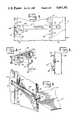
- FIG. 1is a perspective view of a drawer, drawer slide, slide receiver, and slide receiver support, all adapted to be mounted in a cabinet.
- FIG. 2is a cut-away side view of the right side of the cabinet shown in FIG. 1, illustrating the slide receiver supports and their attachment to the slide receiver.
- FIG. 3is a second cut-away view of the same elements shown in FIG. 2, with the slide lock rotated to the release position.
- FIG. 4is cut-away perspective view of a slide receiver and slide receiver support before insertion of a guide pin into the slide receiver support.
- FIG. 5is a cross sectional view along line 5--5 of FIG. 2 showing the slide receiver and slide receiver support.
- FIG. 6is an internal perspective view looking from below the supports to a drawer, and showing the connection of a drawer stop to the drawer catch of a slide lock.
- the front of the cabinetis to the right.
- FIG. 7is a horizontal rear sectional view of a drawer having drawer stops interacting with the drawer catches of the slide locks.
- FIG. 8is an expanded view of the left side portion of the illustration of FIG. 7 showing details of a drawer stop held by the drawer catch of a slide lock.
- FIG. 9is an expanded view of the left side portion of FIG. 7 showing a drawer stop in the release position.
- FIG. 10is a top view of a typical drawer stop.
- FIG. 11is a front view of the drawer stop of FIG. 10.
- FIG. 12is top view of typical slide lock.
- FIG. 13is a front view of the slide lock of FIG. 12.
- the preferred embodiment of this inventionis a removably drawer with a slide mechanism interlocking with that drawer for use in metal cabinetry and the like. As disclosed in this specification, the preferred embodiment is for use with such metal cabinets as are frequently used by machine shops, carpentry shops, or related facilities for holding tools, tool supplies, and similar materials.
- each drawer 12has a pull 14, a rear 16, a right side 18 and left side 20.
- the cabinethas a right side 22 and a left side 24.
- each drawerhas a pair of slides 26.
- the cabinet 10has a support mechanism to hold the slides 26, comprising slide receivers 28 positioned by slide receiver supports 30.
- the front slide receiver supportis also part of the structural frame for the cabinet 10.
- each slide 26has one or more tongue portions 32 that mate within a groove 34 in each slide receiver 28.
- each slide receiverhas an end stop 36 that prevents a slide 26 from moving beyond the internal end of any slide receiver 28.
- FIG. 2specificly shows a drawer 12 fully inserted into a cabinet 10.
- the slide receivers 28are held in the slide receiver supports 30 by means of a guide pin 38.
- each slide receiver supporthas a plurality of pin holes 40 that mate with the guide pins 38.
- Each pin hole 40has a pin slot 42 extending transverse of the slide receiver supports. All pin slots 42 are oriented on the same side of the pin holes 40; in the preferred embodiment, the pin slots 42 are all to the rear of the pin holes 40.
- the mechanism for securing the slide receiver 28 in the slide receiver support 30, in the preferred embodiment,is a slide lock 44.
- the configuration of the slide 44is best illustrated by FIGS. 12 and 13.
- Each slide lock 44is pivotably mounted to slide receivers 28 through a pivot hole 46.
- the slide lock 44is attached to the slide receiver 28 through the pivot hole 46 by use of a pivot pin 48 inserted through the pivot hole.
- Each slide lock 44has a slanted side 50 and a lock side 52.
- the slide lock 44is positioned on the slide receiver 28 so that the lock side 52 will be in flush contact with a slide receiver support 38 in one rotational position (known as a "lock" position).
- the slide lock 44can also pivot away from the slide receiver 28 allowing movement of the guide pin 38 out of the pin slot 42 and into the pin holes 40.
- the slanted side 50allows such rotation of the slide lock 44 without interference between the slide lock and the slide receiver.
- the pivot pin 48is constructed to maintain friction between the slide lock 44 and a slide receiver 28. Such friction can be maintained, for example, by using a bolt for the pivot 48 and tightening the bolt sufficient to produce the necessary friction.
- Each drawerpreferrable has two drawer stops 54 mounted to interact with the slide lock 44. Details of the drawer stops 54 are shown in FIGS. 10-11.
- Each drawer stop 54includes a ledge 56 and a drawer flange 58.
- Each drawer stop 54also has a nose 60 with a slot 62.
- each drawer stop 54has a bolt hole 64 adapted to allow a bolt 66 to mount the drawer stop to the rear 16 of the drawer 12.
- the interlock between the drawer 12 and the slide receiver 28occurs through contact of the nose 60 with the slide lock 44.
- the slide lock 44includes a drawer catch 68 that extends toward the drawer from the slide lock.
- the nose 60is in line with the drawer catch 68.
- the drawer 12then cannot be pulled out of the cabinet 10 because the drawer is held in place by the force of the drawer catch 68 against the nose 60.
- the drawer stop 54can move between a catch position (illustrated in FIG. 8) and a release position illustrated in FIG. 9).
- the drawer stop 54pivots about the bolt 66 mounted in the rear 16 of the drawer 12.
- the rear 16 of the drawer 12has a pair of flange slots 70, one for each drawer stop.
- the drawer flange 58In the release position, the drawer flange 58 is held by the top of the flange slot 70, limiting the rotation of the drawer stop 54 (the drawer stop rotates clock wise as viewed in FIG. 9).
- the catch positionthe drawer flange 58 rests against the bottom of the flange slot 70, leaving the nose 60 in a direct line with the drawer catch 68.
- drawer stop 54Additional features include a slot 62 in the drawer stop, which allows the drawer 12 to move along the slide receiver 28 without having the drawer stop 54 rub against the corner of the slide receiver (as best illlustrated in FIG. 8). Additionaly, the drawer stop 54 has a ledge 56, providing additional strength to the nose portion.
- An alternative embodiment of the above described structurecan be constructed with the slide receiver support made an integral part of the frame 72 of the cabinet 10. For example, referring to FIG. 1, the front slide receiver support of the cabinet 10 is part of the frame, while the rear slide receiver support is a seperately mounted element. Instead, the rear frame 72 can have the pin holes and pin slots placed directly thereon eliminating one of the elements.
- the slide receiver supportsmay be installed at any height that corresponds to the pin holes and pin slots.
- a cabinet or other item of furniturecan be construsted with several small drawers, or a few large drawers, or any combination of large and small drawers.
- the slide 44securely fastens the slide receiver 28 to a slide receiver support 30, thereby maintaining the guide pins 38 in the pins slots 42 rather than in the pin holes 40 (which would allow the guide pin to come out of the slide receiver supports 30).
Landscapes
- Drawers Of Furniture (AREA)
Abstract
Description
This invention relates to mechanisms for drawers contained in cabinets or the like, and more particularly relates to an improved mechanism for the interlock of a drawer with a removable and adjustable drawer slide.
Although drawer slides and mechanisms for connecting drawers to such slides are commonplace, the most frequent structures used in the industry for such drawers and slides are relatively complex. In almost all instances, cabinets or other furniture adapted to carry drawer are designed for a single number of drawers to be contained in the cabinet, and can not be modified to carry variable numbers of drawers of variable sizes placed in variable positions.
Various prior art structures have been created that allow drawer slides to be retained in multiple positions. For example Ames, U.S. Pat. No. 700,721 issued May 27, 1902 for a "Refrigerator Case" discloses a support shelf that is movable to a variety of different positions in a refrigerator case. Rock, et al., U.S. Pat. No. 4,090,753 issued May 23, 1978 for a "Fastening Device", discloses a slide support device for an adjustable front panel of pull-out furniture parts, such drawers. Rock is designed to cooperate with the conventional roller type drawer slide mechanism. Ohnstrand, U.S. Pat. No. 1,247,712 issued Nov. 27, 1917 for "Furniture" discloses a construction for furniture such as a desk where drawer slides are removable and cooperate with various slots in a sheet metal cabinet.
Each of the above patents addresses the need for adjustable drawer slide mechanisms, and to some extent address the desire for simplicity of drawer slide mechanisms. However, in each instance the various mechanisms, while effective in providing useful drawer mechanisms, lack either the desired simplicity or the complete flexibility appropriate for an interchangeable drawer slide mechanism.
It is therefore an object of this invention to provide a drawer slide mechanism with drawer and slide interlock that is simple and comprised of a relatively few number of parts.
Another object of this invention is to provide a drawer and interlocking drawer slide mechanism that allows the position of the drawer slides and hence the configuration of drawers and the cabinet to be readily adjusted.
A further object of this invention is to provide a drawer slide mechanism and interlocking drawer that is relatively easy to operate and adjust.
Yet another object of this invention is to provide a drawer and interlocking drawer slide mechanism that is simple and inexpensive to fabricate.
Still another object of this invention is to provide a drawer and interlocking drawer slide mechanism that, although adjustable, may be easily secured in place such that the mechanism will not dislodge under relatively heavy use.
Another object of this invention is to provide a drawer slide mechanism that adapts itself to use in a wide variety of different drawer constructions, cabinets, and other furniture.
These and other objects of the invention are achieved by providing a drawer with an interlocking drawer slide mechanism. The mechanism includes a pair of slides, each attached to one side of the drawer. Each slide is mateable with a slide receiver, and each slide receiver has a pair of guide pins that are adapted to support the slide receivers. A plurality of slide receivers supports with openings mating with the guide pins are used to support the slide receivers when the guide pins are inserted into any of a plurality of openings in the slide receiver supports. Each slide receiver has a slide lock rotatably mounted on the receiver. The slide locks move between a "lock" position when secured against one of the slide receivers supports, and an "open" position when away from the same support. Each slide lock also has a drawer catch. The mechanism includes a pair of drawer stops each rotatably mounted on the drawer and moving between a catch position where part of the drawer stop catches the drawer catch and a release position, allowing the drawer to be removed from the slide receiver without the drawer stop contacting the drawer catch of the slide lock.
FIG. 1 is a perspective view of a drawer, drawer slide, slide receiver, and slide receiver support, all adapted to be mounted in a cabinet.
FIG. 2 is a cut-away side view of the right side of the cabinet shown in FIG. 1, illustrating the slide receiver supports and their attachment to the slide receiver.
FIG. 3 is a second cut-away view of the same elements shown in FIG. 2, with the slide lock rotated to the release position.
FIG. 4 is cut-away perspective view of a slide receiver and slide receiver support before insertion of a guide pin into the slide receiver support.
FIG. 5 is a cross sectional view alongline 5--5 of FIG. 2 showing the slide receiver and slide receiver support.
FIG. 6 is an internal perspective view looking from below the supports to a drawer, and showing the connection of a drawer stop to the drawer catch of a slide lock. In FIG. 6, the front of the cabinet is to the right.
FIG. 7 is a horizontal rear sectional view of a drawer having drawer stops interacting with the drawer catches of the slide locks.
FIG. 8 is an expanded view of the left side portion of the illustration of FIG. 7 showing details of a drawer stop held by the drawer catch of a slide lock.
FIG. 9 is an expanded view of the left side portion of FIG. 7 showing a drawer stop in the release position.
FIG. 10 is a top view of a typical drawer stop.
FIG. 11 is a front view of the drawer stop of FIG. 10.
FIG. 12 is top view of typical slide lock.
FIG. 13 is a front view of the slide lock of FIG. 12.
In the detailed description, directional terms such as upper, lower, left, and right, and the like are used to relate the invention to the drawer and drawer slide mechanism shown in FIG. 1. Terms of this type are used for the convenience of person of ordinary skill in the art, and are not intended to limit the scope with any patent issuing on the present invention, unless expressly included in the claims.
The preferred embodiment of this invention is a removably drawer with a slide mechanism interlocking with that drawer for use in metal cabinetry and the like. As disclosed in this specification, the preferred embodiment is for use with such metal cabinets as are frequently used by machine shops, carpentry shops, or related facilities for holding tools, tool supplies, and similar materials.
Referring now to the drawings and referring in particular to FIG. 1, the preferred embodiment of the invention is adapted for use with acabinet 10 having one ormore drawers 12. Like all such drawers, eachdrawer 12 has apull 14, a rear 16, aright side 18 andleft side 20. Likewise, the cabinet has aright side 22 and aleft side 24.
To mount thedrawer 12 in thecabinet 10, each drawer has a pair ofslides 26. Thecabinet 10 has a support mechanism to hold theslides 26, comprisingslide receivers 28 positioned by slide receiver supports 30. In the preferred embodiment, the front slide receiver support is also part of the structural frame for thecabinet 10.
The preferred embodiment in the invention includes a tongue and groove mounting of theslides 26 in theslide receivers 28. Accordingly, eachslide 26 has one ormore tongue portions 32 that mate within agroove 34 in eachslide receiver 28. Also in the preferred embodiment, each slide receiver has anend stop 36 that prevents aslide 26 from moving beyond the internal end of anyslide receiver 28.
Referring now to FIGS. 2-5, the details of the interaction between the slides, slide receivers and slide locks is disclosed. FIG. 2 specificly shows adrawer 12 fully inserted into acabinet 10. In the preferred embodiment, theslide receivers 28 are held in the slide receiver supports 30 by means of aguide pin 38. As is best seen in FIGS. 4 & 5, each slide receiver support has a plurality ofpin holes 40 that mate with theguide pins 38. Eachpin hole 40 has apin slot 42 extending transverse of the slide receiver supports. Allpin slots 42 are oriented on the same side of thepin holes 40; in the preferred embodiment, thepin slots 42 are all to the rear of thepin holes 40. Mounting theslide receivers 28 in the slide receiver supports 30 is thus a matter of inserting the guide pins 38 into the appropriate pin holes 40, as best shown in FIG. 3. The slide receiver supports 30 are then moved rearward forcing the guide pins 38 into thepin slots 42, as is best shown in FIG. 2.
The mechanism for securing theslide receiver 28 in theslide receiver support 30, in the preferred embodiment, is aslide lock 44. The configuration of theslide 44 is best illustrated by FIGS. 12 and 13. Eachslide lock 44 is pivotably mounted to slidereceivers 28 through apivot hole 46. Theslide lock 44 is attached to theslide receiver 28 through thepivot hole 46 by use of apivot pin 48 inserted through the pivot hole. Eachslide lock 44 has a slantedside 50 and alock side 52. Theslide lock 44 is positioned on theslide receiver 28 so that thelock side 52 will be in flush contact with aslide receiver support 38 in one rotational position (known as a "lock" position). Theslide lock 44 can also pivot away from theslide receiver 28 allowing movement of theguide pin 38 out of thepin slot 42 and into the pin holes 40. The slantedside 50 allows such rotation of theslide lock 44 without interference between the slide lock and the slide receiver. To prevent to slidelock 44 from moving merely due to gravity, thepivot pin 48 is constructed to maintain friction between theslide lock 44 and aslide receiver 28. Such friction can be maintained, for example, by using a bolt for thepivot 48 and tightening the bolt sufficient to produce the necessary friction.
Operation of the interlock between thedrawers 12 andslide receivers 28 is best illustrated by reference to FIGS. 6-9. Each drawer preferrable has two drawer stops 54 mounted to interact with theslide lock 44. Details of the drawer stops 54 are shown in FIGS. 10-11. Eachdrawer stop 54 includes aledge 56 and adrawer flange 58. Each drawer stop 54 also has anose 60 with aslot 62. Finally, eachdrawer stop 54 has abolt hole 64 adapted to allow abolt 66 to mount the drawer stop to the rear 16 of thedrawer 12.
The interlock between thedrawer 12 and theslide receiver 28 occurs through contact of thenose 60 with theslide lock 44. As best shown in FIG. 12, theslide lock 44 includes adrawer catch 68 that extends toward the drawer from the slide lock. When thedrawer stop 54 is properly mounted, thenose 60 is in line with thedrawer catch 68. As best shown in FIG. 6, thedrawer 12 then cannot be pulled out of thecabinet 10 because the drawer is held in place by the force of thedrawer catch 68 against thenose 60.
In the preferred embodiment, thedrawer stop 54 can move between a catch position (illustrated in FIG. 8) and a release position illustrated in FIG. 9). Thedrawer stop 54 pivots about thebolt 66 mounted in the rear 16 of thedrawer 12. To limit rotation of thedrawer stop 54, the rear 16 of thedrawer 12 has a pair offlange slots 70, one for each drawer stop. In the release position, thedrawer flange 58 is held by the top of theflange slot 70, limiting the rotation of the drawer stop 54 (the drawer stop rotates clock wise as viewed in FIG. 9). In the catch position, thedrawer flange 58 rests against the bottom of theflange slot 70, leaving thenose 60 in a direct line with thedrawer catch 68.
Additional features of thedrawer stop 54 include aslot 62 in the drawer stop, which allows thedrawer 12 to move along theslide receiver 28 without having thedrawer stop 54 rub against the corner of the slide receiver (as best illlustrated in FIG. 8). Additionaly, thedrawer stop 54 has aledge 56, providing additional strength to the nose portion. An alternative embodiment of the above described structure can be constructed with the slide receiver support made an integral part of theframe 72 of thecabinet 10. For example, referring to FIG. 1, the front slide receiver support of thecabinet 10 is part of the frame, while the rear slide receiver support is a seperately mounted element. Instead, therear frame 72 can have the pin holes and pin slots placed directly thereon eliminating one of the elements.
Operation of the removeable drawer slide and interlock begins with installation of the slide receivers on to the slide support. As is readily noted, the slide receiver supports may be installed at any height that corresponds to the pin holes and pin slots. Thus, for example, a cabinet or other item of furniture can be construsted with several small drawers, or a few large drawers, or any combination of large and small drawers. In each instance, theslide 44 securely fastens theslide receiver 28 to aslide receiver support 30, thereby maintaining the guide pins 38 in thepins slots 42 rather than in the pin holes 40 (which would allow the guide pin to come out of the slide receiver supports 30).
Removal of adrawer 12 from the cabinet pin is simply a matter of reaching with one hand and moving the drawer stop 54 from the catch position to the release position. Since theslide lock 44 is always mounted on the slide receiver support at the front of thecabinet 10, release of the drawer from the interlock mechanism is readily accomplished because of the proximaty of the drawer stop and its related mechanism to the front of the cabinet when the drawer is pulled to its full extent forward and thenose 60 is in contact withdrawer catch 68.
While the preferred embodiments of the present invention have been set forth in the above detailed description, the preferred embodiments are only examples of the invention. Other modifications may be used without departing from the scope of the present invention, and the invention is limited only by the following claims and their equivalents.
Claims (7)
1. A drawer and interlocking drawer mechanism, comprising, in combination:
a drawer;
a pair of slides with one slide attached to each side of the drawer;
a pair of slide receivers mateable with the slides, each slide receiver having a pair of guide pins adapted to support the slide receiver;
a plurality of slide receiver supports each having a plurality of openings mateable with the guide pins such that when the guide pins are inserted into one of the openings in each support, the slide receivers are supported by the slide receiver supports;
a pair of slide locks rotatably mounted on each slide receiver and adapted to rotatably move between a lock position against one of the slide receiver supports and an open position away from the same support, each slide lock having a drawer catch; and
a pair of drawer stops, each rotatably mounted on the drawer and adapted to rotate between a catch position where the drawer stop will catch the drawer catch at one point during movement of a slide in the slide receiver and a release position where the drawer stop will never catch the drawer catch during movement of the slides in the slide receivers, whereby the slide receivers are releasably held in fixed position by the slide locks, and the drawer may be removed from the slide receivers by rotating the drawer stops to the release position and withdrawing the drawer from the slide.
2. A drawer and interlocking drawer mechanism as claimed in claim 1, wherein the drawer stops further comprise a protruding flange, and the drawer further comprises one or more flange slots mateable with the drawer flange and adapted to limit rotation of the drawer stop.
3. A drawer and interlocking drawer mechanism as claimed in claim 1, wherein the slide lock further comprises a lock side adapted to contact a slide receiver support, and the drawer catch comprises a flange extending from the lock side of the slide lock.
4. A drawer and interlocking drawer mechanism as claimed in claim 1, wherein the drawer and mechanism are part of a cabinet having a frame, and one or more of the slide receiver supports acts as an element of that frame.
5. A drawer and interlocking drawer mechanism as claimed in claim 1, wherein the guide pins comprise a shaft with an enlarged head, and the openings in the slide receiver supports comprise a slot narrower than the head of the guide pins but wider than the shaft, with the slot being part of a pin hole that is wider than the guide pin heads, whereby the slide receivers are assembled to the slide receiver supports by inserting the enlarged head of the guide pins into the pin holes and thereafter sliding the shafts into the slots, such that movement of the slide receivers is limited to sliding movement along the slots.
6. A drawer and interlocking drawer mechanism as claimed in claim 5, wherein the slide lock operates by preventing movement of the slide receiver in the longitudinal direction of the slots.
7. A drawer and interlocking drawer mechanism as claimed in claim 1, wherein the slide receivers each further comprise an end stop limiting movement of the slides into the slide receivers.
Priority Applications (1)
| Application Number | Priority Date | Filing Date | Title |
|---|---|---|---|
| US06/919,686US4681381A (en) | 1986-10-16 | 1986-10-16 | Removable drawer slide and interlock with drawer |
Applications Claiming Priority (1)
| Application Number | Priority Date | Filing Date | Title |
|---|---|---|---|
| US06/919,686US4681381A (en) | 1986-10-16 | 1986-10-16 | Removable drawer slide and interlock with drawer |
Publications (1)
| Publication Number | Publication Date |
|---|---|
| US4681381Atrue US4681381A (en) | 1987-07-21 |
Family
ID=25442476
Family Applications (1)
| Application Number | Title | Priority Date | Filing Date |
|---|---|---|---|
| US06/919,686Expired - LifetimeUS4681381A (en) | 1986-10-16 | 1986-10-16 | Removable drawer slide and interlock with drawer |
Country Status (1)
| Country | Link |
|---|---|
| US (1) | US4681381A (en) |
Cited By (71)
| Publication number | Priority date | Publication date | Assignee | Title |
|---|---|---|---|---|
| FR2638951A1 (en)* | 1988-11-16 | 1990-05-18 | Dito Sama | Tray support with racks and runners for baked goods |
| US5098175A (en)* | 1989-10-27 | 1992-03-24 | International Business Machines Corporation | Removable guide apparatus for a rail-mounted device employed in a computer |
| USD350646S (en) | 1993-04-08 | 1994-09-20 | Rubbermaid Incorporated | Lid for tool chest |
| USD361910S (en) | 1993-04-08 | 1995-09-05 | Rubbermaid Incorporated | Tool chest |
| US5470143A (en)* | 1994-03-24 | 1995-11-28 | Steelcase Inc. | Self-locking snap-on suspension unit for furniture cabinets and the like |
| US5472270A (en)* | 1994-07-05 | 1995-12-05 | Midmark Corporation | Convertible cabinet |
| US5483902A (en)* | 1993-09-14 | 1996-01-16 | Grosch; Peter T. | Adjustable work surface for computer stations |
| US5496105A (en)* | 1994-07-14 | 1996-03-05 | Midmark Corporation | Cabinet having drawers with cover flanges |
| US5549377A (en)* | 1995-06-08 | 1996-08-27 | Snap-On Technologies, Inc. | Corrugated three-piece drawer slide assembly |
| US5570941A (en)* | 1994-02-25 | 1996-11-05 | Julius Blum Gesellschaft M.B.H. | Supporting rail fitting or assembly for drawer |
| US5601350A (en)* | 1994-02-25 | 1997-02-11 | Julius Blum Gesellschaft M.B.H. | Support rail for a drawer pull out guide |
| US5671986A (en)* | 1993-11-12 | 1997-09-30 | Vinet; Pierre | Dishwasher rack support assembly |
| US5720535A (en)* | 1996-08-30 | 1998-02-24 | Waterloo Industries, Inc. | Cabinet construction and locking system |
| US5785401A (en)* | 1996-06-21 | 1998-07-28 | Herman Miller, Inc. | Vertical support for a slide mechanism in a cabinet |
| USD434225S (en)* | 1999-11-10 | 2000-11-28 | Stack-On Products Co. | Storage container with lid storage |
| USD449181S1 (en) | 1999-07-20 | 2001-10-16 | Stack-On Products Co. | Storage cabinet |
| US6373707B1 (en) | 2000-06-02 | 2002-04-16 | Astec International Limited | Module mounting slide clamp mechanism |
| US6375235B1 (en) | 2000-05-25 | 2002-04-23 | Waterloo Industries, Inc. | Drawer latch |
| US6378966B1 (en)* | 2000-09-07 | 2002-04-30 | International Business Machines Corporation | Device for use with a computer drawer assembly |
| US6409292B1 (en)* | 1999-02-03 | 2002-06-25 | Janomed Produktions- Und Vertriebs | Storage cupboard, in particular for hospital requirements |
| US6416145B1 (en)* | 1997-04-23 | 2002-07-09 | Accuride International, Inc. | Drawer slide undermount bracket with flexible locking tab |
| US6616252B2 (en)* | 2001-07-30 | 2003-09-09 | Hewlett-Packard Development Company, L.P. | Permanently attached rackmount handles and spacing brackets |
| US20030209957A1 (en)* | 2002-05-13 | 2003-11-13 | Hightower Robert C. | Rollout tray mounting system for cabinet |
| EP1400189A1 (en)* | 2002-09-20 | 2004-03-24 | BERTELLO S.p.A. | Guiding mechanism for a drawer |
| EP1362526A3 (en)* | 2002-05-13 | 2004-06-09 | Tenn-Tex Plastics, Inc. | Rollout tray mounting system for cabinet |
| US6752479B2 (en)* | 2000-11-24 | 2004-06-22 | Kendro Laboratory Products Gmbh | Object storage station and climatic chamber |
| US20040232148A1 (en)* | 2003-05-19 | 2004-11-25 | Gl&V Management Hungary Kft. | Slide guide assembly and slider kit for floating cover of digester tank and associated method |
| US20040263033A1 (en)* | 2003-03-28 | 2004-12-30 | Metal Fabricating Corporation | Cabinet runner side wall extension |
| US6893091B1 (en)* | 2002-05-07 | 2005-05-17 | Martin Fenner | Side-vented enclosure and telescoping rail system |
| US20050168115A1 (en)* | 2004-02-04 | 2005-08-04 | Brian Moon | Drawer cabinet storage kit |
| US20050225108A1 (en)* | 2004-04-09 | 2005-10-13 | Panasewicz Dale A | Adjustable shelving system for vehicles |
| US20060066190A1 (en)* | 2004-09-29 | 2006-03-30 | Mike Edward Hay | Friction slide |
| US20060103279A1 (en)* | 2004-11-15 | 2006-05-18 | Hsing Lyiang Industry Co., Ltd. | Drawer assembly with a stop mechanism |
| USD525934S1 (en) | 2004-04-09 | 2006-08-01 | America's Body Company | Truck shelving system |
| USD536659S1 (en) | 2005-09-28 | 2007-02-13 | L&P Property Management Company | Truck shelving system |
| US20070069542A1 (en)* | 2005-09-28 | 2007-03-29 | America's Body Company | Adjustable shelving and storage system for vehicles |
| US20070103039A1 (en)* | 2005-11-10 | 2007-05-10 | Holcomb Gregory J | Tool storage system |
| USD553555S1 (en) | 2005-09-28 | 2007-10-23 | L&P Property Management Company | Truck shelving system |
| US20070252490A1 (en)* | 2003-04-23 | 2007-11-01 | Cleveland Terri P | Stackable Blow Molded Cabinet |
| US20080012375A1 (en)* | 2004-04-09 | 2008-01-17 | L&P Property Management Company | Adjustable shelving system for vehicles |
| US20080030111A1 (en)* | 2006-08-01 | 2008-02-07 | Csps Metal Co., Ltd. | Slipping-proof kit drawer structure |
| US20080092784A1 (en)* | 2006-09-21 | 2008-04-24 | Lufthansa Technik Ag | Folding table arrangement |
| US20080164387A1 (en)* | 2007-01-08 | 2008-07-10 | Porreca Fedele Phil Anthony | Superior shelf system |
| US20080246377A1 (en)* | 2007-04-04 | 2008-10-09 | Shun Lung Huang | Cabinet having drawer anchoring device |
| US20080278043A1 (en)* | 2007-05-08 | 2008-11-13 | Waterloo Industries, Inc. | Drawer lock mechanism |
| US20080279490A1 (en)* | 2007-05-08 | 2008-11-13 | Waterloo Industries, Inc. | Sliding friction reducer |
| US7452039B1 (en) | 2004-08-10 | 2008-11-18 | Metal Fabricating Corporation | Cabinet shelf with keyed slot |
| US20090127987A1 (en)* | 2007-11-16 | 2009-05-21 | Waterloo Industries, Inc. | Door latch |
| US20090195129A1 (en)* | 2006-07-05 | 2009-08-06 | Shinji Osawa | Rack device and incubator having the same |
| CN100546675C (en)* | 2006-11-28 | 2009-10-07 | 张建明 | Carriage mechanism for accessing demolition tools |
| EP2127559A1 (en) | 2008-05-30 | 2009-12-02 | Hong Fu Jin Precision Industry (ShenZhen) Co. Ltd. | Slide rail apparatus |
| US7810653B2 (en) | 2003-10-02 | 2010-10-12 | Hewlett-Packard Development Company, L.P. | Apparatus and method for mounting a device to a rack system |
| US20100295432A1 (en)* | 2009-05-19 | 2010-11-25 | Hightower Robert C | Inset Undermounted Bracket for Drawer and Tray Slides in Cabinetry |
| US20100326936A1 (en)* | 2009-06-24 | 2010-12-30 | Dejana Corgo & Van Interiors Inc. | Rack and tray device |
| US20110174678A1 (en)* | 2010-01-21 | 2011-07-21 | Peggy Jean Champlin | Gift wrap organizer |
| USD643656S1 (en) | 2009-06-09 | 2011-08-23 | Metal Fabricating Corporation | Front wall of a cabinet shelf |
| US20110254420A1 (en)* | 2010-04-16 | 2011-10-20 | Kevin Esparza | Adjustable Cabinet Drawer Pullout System |
| US20120013235A1 (en)* | 2010-07-15 | 2012-01-19 | Oki Electric Industry Co., Ltd. | Slide rail structure |
| USD660462S1 (en) | 2010-11-02 | 2012-05-22 | Quality Craft Industries Inc. | Trim for drawer pull |
| US8287060B1 (en) | 2003-10-22 | 2012-10-16 | Metal Fabricating Corporation | Cabinet shelf with keyed slot |
| US8322545B1 (en) | 2006-12-21 | 2012-12-04 | Metal Fabricating Corporation | Curved bin for shelf |
| US8608261B2 (en) | 2010-06-22 | 2013-12-17 | Quality Craft Industries Inc. | Drawer latch |
| US20140152161A1 (en)* | 2010-06-30 | 2014-06-05 | Carefusion 303, Inc. | Configurable cabinet for hanging and shelved items |
| US9295327B2 (en) | 2014-08-19 | 2016-03-29 | Haworth, Inc. | Side mounted drawer slide |
| US20160184816A1 (en)* | 2014-12-16 | 2016-06-30 | Binder Gmbh | Interior vessel of a simulation cabinet and simulation cabinet with an interior vessel |
| US9422750B2 (en) | 2013-08-13 | 2016-08-23 | Waterloo Industries, Inc. | Range limited latch |
| US9894793B1 (en)* | 2017-03-09 | 2018-02-13 | International Business Machines Corporation | Cable management bracket |
| US20190245334A1 (en)* | 2018-02-07 | 2019-08-08 | King Slide Works Co., Ltd. | Connection device for cable management device and slide rail assembly |
| USD939803S1 (en)* | 2020-05-28 | 2021-12-28 | William Madison | Memorial cabinet |
| US11391082B2 (en)* | 2020-01-02 | 2022-07-19 | Bonita Hervey | Dresser integrated safe apparatus |
| US20250288102A1 (en)* | 2024-03-12 | 2025-09-18 | Changsha Baituo Import and Export Co., Ltd. | Cabinet with easy-to-assemble/disassemble drawer rail |
Citations (17)
| Publication number | Priority date | Publication date | Assignee | Title |
|---|---|---|---|---|
| US700721A (en)* | 1901-07-05 | 1902-05-27 | William H Ames | Refrigerator-case. |
| US1247712A (en)* | 1912-11-04 | 1917-11-27 | U S Steel Furniture Company | Furniture. |
| US1477278A (en)* | 1921-12-17 | 1923-12-11 | Lyon Metallic Mfg Company | Cabinet drawer |
| US1569158A (en)* | 1923-07-19 | 1926-01-12 | Fred W Tobey | Filing cabinet |
| US1958686A (en)* | 1932-02-08 | 1934-05-15 | Corry Jamestown Mfg Corp | Metal furniture |
| US2528910A (en)* | 1948-02-27 | 1950-11-07 | Browne Morse Company | Snap-on drawer lock |
| US2859070A (en)* | 1954-05-21 | 1958-11-04 | Mc Graw Edison Co | Extension hanger for cabinet drawer |
| GB910103A (en)* | 1960-08-22 | 1962-11-07 | Ile De Rech S & D Etudes Ind S | Improvements in or relating to means for mounting horizontal guide members for drawers etc. in furniture and the like |
| US3092429A (en)* | 1960-05-23 | 1963-06-04 | David Ind | Chassis slide mechanism |
| US3123419A (en)* | 1961-08-23 | 1964-03-03 | Lock for drawer assemblies | |
| US3124402A (en)* | 1964-03-10 | Pan and tray supports | ||
| US3572874A (en)* | 1968-10-23 | 1971-03-30 | Schaefer Gmbh Fritz | Metal cabinets |
| US3624703A (en)* | 1969-12-05 | 1971-11-30 | Whirlpool Co | Icemaker cutter-grid-mounting means |
| GB1433736A (en)* | 1972-02-04 | 1976-04-28 | Birmingham Pallet Co Ltd | Pallet convertors |
| US4065196A (en)* | 1976-02-02 | 1977-12-27 | Hardware Designers, Inc. | Positive action front release drawer slide assembly |
| US4090753A (en)* | 1975-07-03 | 1978-05-23 | Julius Blum Gesellschaft M.B.H. | Fastening device |
| US4191436A (en)* | 1978-07-25 | 1980-03-04 | The Streakers International Incorporated | Cabinet for use in mobile vehicle |
- 1986
- 1986-10-16USUS06/919,686patent/US4681381A/ennot_activeExpired - Lifetime
Patent Citations (17)
| Publication number | Priority date | Publication date | Assignee | Title |
|---|---|---|---|---|
| US3124402A (en)* | 1964-03-10 | Pan and tray supports | ||
| US700721A (en)* | 1901-07-05 | 1902-05-27 | William H Ames | Refrigerator-case. |
| US1247712A (en)* | 1912-11-04 | 1917-11-27 | U S Steel Furniture Company | Furniture. |
| US1477278A (en)* | 1921-12-17 | 1923-12-11 | Lyon Metallic Mfg Company | Cabinet drawer |
| US1569158A (en)* | 1923-07-19 | 1926-01-12 | Fred W Tobey | Filing cabinet |
| US1958686A (en)* | 1932-02-08 | 1934-05-15 | Corry Jamestown Mfg Corp | Metal furniture |
| US2528910A (en)* | 1948-02-27 | 1950-11-07 | Browne Morse Company | Snap-on drawer lock |
| US2859070A (en)* | 1954-05-21 | 1958-11-04 | Mc Graw Edison Co | Extension hanger for cabinet drawer |
| US3092429A (en)* | 1960-05-23 | 1963-06-04 | David Ind | Chassis slide mechanism |
| GB910103A (en)* | 1960-08-22 | 1962-11-07 | Ile De Rech S & D Etudes Ind S | Improvements in or relating to means for mounting horizontal guide members for drawers etc. in furniture and the like |
| US3123419A (en)* | 1961-08-23 | 1964-03-03 | Lock for drawer assemblies | |
| US3572874A (en)* | 1968-10-23 | 1971-03-30 | Schaefer Gmbh Fritz | Metal cabinets |
| US3624703A (en)* | 1969-12-05 | 1971-11-30 | Whirlpool Co | Icemaker cutter-grid-mounting means |
| GB1433736A (en)* | 1972-02-04 | 1976-04-28 | Birmingham Pallet Co Ltd | Pallet convertors |
| US4090753A (en)* | 1975-07-03 | 1978-05-23 | Julius Blum Gesellschaft M.B.H. | Fastening device |
| US4065196A (en)* | 1976-02-02 | 1977-12-27 | Hardware Designers, Inc. | Positive action front release drawer slide assembly |
| US4191436A (en)* | 1978-07-25 | 1980-03-04 | The Streakers International Incorporated | Cabinet for use in mobile vehicle |
Cited By (101)
| Publication number | Priority date | Publication date | Assignee | Title |
|---|---|---|---|---|
| FR2638951A1 (en)* | 1988-11-16 | 1990-05-18 | Dito Sama | Tray support with racks and runners for baked goods |
| US5098175A (en)* | 1989-10-27 | 1992-03-24 | International Business Machines Corporation | Removable guide apparatus for a rail-mounted device employed in a computer |
| USD350646S (en) | 1993-04-08 | 1994-09-20 | Rubbermaid Incorporated | Lid for tool chest |
| USD361910S (en) | 1993-04-08 | 1995-09-05 | Rubbermaid Incorporated | Tool chest |
| US5483902A (en)* | 1993-09-14 | 1996-01-16 | Grosch; Peter T. | Adjustable work surface for computer stations |
| US5671986A (en)* | 1993-11-12 | 1997-09-30 | Vinet; Pierre | Dishwasher rack support assembly |
| US5570941A (en)* | 1994-02-25 | 1996-11-05 | Julius Blum Gesellschaft M.B.H. | Supporting rail fitting or assembly for drawer |
| US5601350A (en)* | 1994-02-25 | 1997-02-11 | Julius Blum Gesellschaft M.B.H. | Support rail for a drawer pull out guide |
| US5470143A (en)* | 1994-03-24 | 1995-11-28 | Steelcase Inc. | Self-locking snap-on suspension unit for furniture cabinets and the like |
| US5472270A (en)* | 1994-07-05 | 1995-12-05 | Midmark Corporation | Convertible cabinet |
| US5496105A (en)* | 1994-07-14 | 1996-03-05 | Midmark Corporation | Cabinet having drawers with cover flanges |
| US5549377A (en)* | 1995-06-08 | 1996-08-27 | Snap-On Technologies, Inc. | Corrugated three-piece drawer slide assembly |
| US5785401A (en)* | 1996-06-21 | 1998-07-28 | Herman Miller, Inc. | Vertical support for a slide mechanism in a cabinet |
| US6042206A (en)* | 1996-06-21 | 2000-03-28 | Herman Miller, Inc. | Vertical support for a slide mechanism in a cabinet |
| US6123402A (en)* | 1996-06-21 | 2000-09-26 | Herman Miller, Inc. | Cabinet having a support for a slide mechanism |
| US5720535A (en)* | 1996-08-30 | 1998-02-24 | Waterloo Industries, Inc. | Cabinet construction and locking system |
| US6416145B1 (en)* | 1997-04-23 | 2002-07-09 | Accuride International, Inc. | Drawer slide undermount bracket with flexible locking tab |
| US6409292B1 (en)* | 1999-02-03 | 2002-06-25 | Janomed Produktions- Und Vertriebs | Storage cupboard, in particular for hospital requirements |
| USD457704S1 (en) | 1999-07-20 | 2002-05-21 | Stack-On Products Co. | Workbench and storage cabinet |
| USD457754S1 (en) | 1999-07-20 | 2002-05-28 | Stack-On Products Co. | Two-door storage cabinet |
| USD449181S1 (en) | 1999-07-20 | 2001-10-16 | Stack-On Products Co. | Storage cabinet |
| USD434225S (en)* | 1999-11-10 | 2000-11-28 | Stack-On Products Co. | Storage container with lid storage |
| US6375235B1 (en) | 2000-05-25 | 2002-04-23 | Waterloo Industries, Inc. | Drawer latch |
| USRE40267E1 (en)* | 2000-05-25 | 2008-04-29 | Waterloo Industries, Inc. | Drawer latch |
| US6373707B1 (en) | 2000-06-02 | 2002-04-16 | Astec International Limited | Module mounting slide clamp mechanism |
| US6378966B1 (en)* | 2000-09-07 | 2002-04-30 | International Business Machines Corporation | Device for use with a computer drawer assembly |
| US6752479B2 (en)* | 2000-11-24 | 2004-06-22 | Kendro Laboratory Products Gmbh | Object storage station and climatic chamber |
| US6616252B2 (en)* | 2001-07-30 | 2003-09-09 | Hewlett-Packard Development Company, L.P. | Permanently attached rackmount handles and spacing brackets |
| US6893091B1 (en)* | 2002-05-07 | 2005-05-17 | Martin Fenner | Side-vented enclosure and telescoping rail system |
| US20050122015A1 (en)* | 2002-05-13 | 2005-06-09 | Hightower Robert C. | Rollout tray mounting system for cabinet |
| US7547080B2 (en) | 2002-05-13 | 2009-06-16 | Tenn-Tex Plastics Inc. | Rollout tray mounting system for cabinet |
| US6840590B2 (en) | 2002-05-13 | 2005-01-11 | Tenn-Tex Plastics, Inc. | Rollout tray mounting system for cabinet |
| EP1362526A3 (en)* | 2002-05-13 | 2004-06-09 | Tenn-Tex Plastics, Inc. | Rollout tray mounting system for cabinet |
| US20030209957A1 (en)* | 2002-05-13 | 2003-11-13 | Hightower Robert C. | Rollout tray mounting system for cabinet |
| US7984954B2 (en) | 2002-05-13 | 2011-07-26 | Tenn-Tex Plastics, Inc. | Rollout tray mounting system for cabinet |
| EP1400189A1 (en)* | 2002-09-20 | 2004-03-24 | BERTELLO S.p.A. | Guiding mechanism for a drawer |
| US20040263033A1 (en)* | 2003-03-28 | 2004-12-30 | Metal Fabricating Corporation | Cabinet runner side wall extension |
| US7306300B2 (en) | 2003-03-28 | 2007-12-11 | Metal Fabricating Corporation | Cabinet runner side wall extension |
| EP1615527A4 (en)* | 2003-04-23 | 2008-06-18 | Brush & Co John D | Stackable blow molded cabinet |
| US20070252490A1 (en)* | 2003-04-23 | 2007-11-01 | Cleveland Terri P | Stackable Blow Molded Cabinet |
| US7748797B2 (en) | 2003-04-23 | 2010-07-06 | John D. Brush & Co., Inc. | Stackable blow molded cabinet |
| US20040232148A1 (en)* | 2003-05-19 | 2004-11-25 | Gl&V Management Hungary Kft. | Slide guide assembly and slider kit for floating cover of digester tank and associated method |
| US7810653B2 (en) | 2003-10-02 | 2010-10-12 | Hewlett-Packard Development Company, L.P. | Apparatus and method for mounting a device to a rack system |
| US8287060B1 (en) | 2003-10-22 | 2012-10-16 | Metal Fabricating Corporation | Cabinet shelf with keyed slot |
| US20050168115A1 (en)* | 2004-02-04 | 2005-08-04 | Brian Moon | Drawer cabinet storage kit |
| US7641253B2 (en) | 2004-04-09 | 2010-01-05 | L&P Property Management Company | Adjustable shelving system for vehicles |
| USD525934S1 (en) | 2004-04-09 | 2006-08-01 | America's Body Company | Truck shelving system |
| US20080012375A1 (en)* | 2004-04-09 | 2008-01-17 | L&P Property Management Company | Adjustable shelving system for vehicles |
| US20050225108A1 (en)* | 2004-04-09 | 2005-10-13 | Panasewicz Dale A | Adjustable shelving system for vehicles |
| US7452039B1 (en) | 2004-08-10 | 2008-11-18 | Metal Fabricating Corporation | Cabinet shelf with keyed slot |
| US7347516B2 (en) | 2004-09-29 | 2008-03-25 | Waterloo Industries, Inc. | Friction slide |
| US20060066190A1 (en)* | 2004-09-29 | 2006-03-30 | Mike Edward Hay | Friction slide |
| US20060103279A1 (en)* | 2004-11-15 | 2006-05-18 | Hsing Lyiang Industry Co., Ltd. | Drawer assembly with a stop mechanism |
| US7784885B2 (en) | 2005-09-28 | 2010-08-31 | L&P Property Management Company | Adjustable shelving and storage system for vehicles |
| USD536659S1 (en) | 2005-09-28 | 2007-02-13 | L&P Property Management Company | Truck shelving system |
| USD553555S1 (en) | 2005-09-28 | 2007-10-23 | L&P Property Management Company | Truck shelving system |
| USD549154S1 (en) | 2005-09-28 | 2007-08-21 | L & P Property Management Company | Truck shelving system |
| US20110018411A1 (en)* | 2005-09-28 | 2011-01-27 | Steiger William D | Adjustable shelving and storage system for vehicles |
| US20070069542A1 (en)* | 2005-09-28 | 2007-03-29 | America's Body Company | Adjustable shelving and storage system for vehicles |
| US20070103039A1 (en)* | 2005-11-10 | 2007-05-10 | Holcomb Gregory J | Tool storage system |
| EP2036456A4 (en)* | 2006-07-05 | 2012-05-30 | Sanyo Electric Co | SHELF DEVICE AND INCUBATOR HAVING THE SAME |
| US8136899B2 (en)* | 2006-07-05 | 2012-03-20 | Sanyo Electric Co., Ltd. | Rack device and incubator having the same |
| US20090195129A1 (en)* | 2006-07-05 | 2009-08-06 | Shinji Osawa | Rack device and incubator having the same |
| US20080030111A1 (en)* | 2006-08-01 | 2008-02-07 | Csps Metal Co., Ltd. | Slipping-proof kit drawer structure |
| US20080092784A1 (en)* | 2006-09-21 | 2008-04-24 | Lufthansa Technik Ag | Folding table arrangement |
| US8028630B2 (en)* | 2006-09-21 | 2011-10-04 | Lufthansa Technik Ag | Folding table arrangement |
| CN100546675C (en)* | 2006-11-28 | 2009-10-07 | 张建明 | Carriage mechanism for accessing demolition tools |
| US8322545B1 (en) | 2006-12-21 | 2012-12-04 | Metal Fabricating Corporation | Curved bin for shelf |
| US20080164387A1 (en)* | 2007-01-08 | 2008-07-10 | Porreca Fedele Phil Anthony | Superior shelf system |
| US20080246377A1 (en)* | 2007-04-04 | 2008-10-09 | Shun Lung Huang | Cabinet having drawer anchoring device |
| US7946663B2 (en) | 2007-05-08 | 2011-05-24 | Waterloo Industries, Inc. | Drawer lock mechanism |
| US20080278043A1 (en)* | 2007-05-08 | 2008-11-13 | Waterloo Industries, Inc. | Drawer lock mechanism |
| US20080279490A1 (en)* | 2007-05-08 | 2008-11-13 | Waterloo Industries, Inc. | Sliding friction reducer |
| US8240786B2 (en) | 2007-11-16 | 2012-08-14 | Waterloo Industries, Inc. | Door latch |
| US20090127987A1 (en)* | 2007-11-16 | 2009-05-21 | Waterloo Industries, Inc. | Door latch |
| EP2127559A1 (en) | 2008-05-30 | 2009-12-02 | Hong Fu Jin Precision Industry (ShenZhen) Co. Ltd. | Slide rail apparatus |
| US8616664B2 (en) | 2009-05-19 | 2013-12-31 | Tenn-Tex Plastics, Inc. | Inset undermounted bracket for drawer and tray slides in cabinetry |
| US20100295432A1 (en)* | 2009-05-19 | 2010-11-25 | Hightower Robert C | Inset Undermounted Bracket for Drawer and Tray Slides in Cabinetry |
| USD643656S1 (en) | 2009-06-09 | 2011-08-23 | Metal Fabricating Corporation | Front wall of a cabinet shelf |
| US8763820B2 (en)* | 2009-06-24 | 2014-07-01 | Charles L. Hanley | Rack and tray device |
| US20100326936A1 (en)* | 2009-06-24 | 2010-12-30 | Dejana Corgo & Van Interiors Inc. | Rack and tray device |
| US20110174678A1 (en)* | 2010-01-21 | 2011-07-21 | Peggy Jean Champlin | Gift wrap organizer |
| US20110254420A1 (en)* | 2010-04-16 | 2011-10-20 | Kevin Esparza | Adjustable Cabinet Drawer Pullout System |
| US8608261B2 (en) | 2010-06-22 | 2013-12-17 | Quality Craft Industries Inc. | Drawer latch |
| US20140152161A1 (en)* | 2010-06-30 | 2014-06-05 | Carefusion 303, Inc. | Configurable cabinet for hanging and shelved items |
| US11234519B2 (en)* | 2010-06-30 | 2022-02-01 | Carefusion 303, Inc. | Configurable cabinet for hanging and shelved items |
| US20120013235A1 (en)* | 2010-07-15 | 2012-01-19 | Oki Electric Industry Co., Ltd. | Slide rail structure |
| USD660462S1 (en) | 2010-11-02 | 2012-05-22 | Quality Craft Industries Inc. | Trim for drawer pull |
| US9422750B2 (en) | 2013-08-13 | 2016-08-23 | Waterloo Industries, Inc. | Range limited latch |
| US9295327B2 (en) | 2014-08-19 | 2016-03-29 | Haworth, Inc. | Side mounted drawer slide |
| US10603663B2 (en)* | 2014-12-16 | 2020-03-31 | Vega Grieshaber Kg | Interior vessel of a simulation cabinet and simulation cabinet with an interior vessel |
| US20160184816A1 (en)* | 2014-12-16 | 2016-06-30 | Binder Gmbh | Interior vessel of a simulation cabinet and simulation cabinet with an interior vessel |
| US20180263134A1 (en)* | 2017-03-09 | 2018-09-13 | International Business Machines Corporation | Cable management bracket |
| US10117348B2 (en)* | 2017-03-09 | 2018-10-30 | International Business Machines Corporation | Cable management bracket |
| US10172250B2 (en)* | 2017-03-09 | 2019-01-01 | International Business Machines Corporation | Cable management bracket |
| US9894793B1 (en)* | 2017-03-09 | 2018-02-13 | International Business Machines Corporation | Cable management bracket |
| US20190245334A1 (en)* | 2018-02-07 | 2019-08-08 | King Slide Works Co., Ltd. | Connection device for cable management device and slide rail assembly |
| US10886713B2 (en)* | 2018-02-07 | 2021-01-05 | King Slide Works Co., Ltd. | Connection device for cable management device and slide rail assembly |
| US11391082B2 (en)* | 2020-01-02 | 2022-07-19 | Bonita Hervey | Dresser integrated safe apparatus |
| USD939803S1 (en)* | 2020-05-28 | 2021-12-28 | William Madison | Memorial cabinet |
| US20250288102A1 (en)* | 2024-03-12 | 2025-09-18 | Changsha Baituo Import and Export Co., Ltd. | Cabinet with easy-to-assemble/disassemble drawer rail |
Similar Documents
| Publication | Publication Date | Title |
|---|---|---|
| US4681381A (en) | Removable drawer slide and interlock with drawer | |
| US4805784A (en) | Slatwall mounting device | |
| US5205524A (en) | Adjustable bracket | |
| US4934645A (en) | Shelving assembly | |
| US4433885A (en) | Lazy susan assembly having a rotational and vertical adjustment mechanism | |
| US4971281A (en) | Anti-dislodgement mechanism | |
| US4155458A (en) | Large tool security storage system | |
| US4006513A (en) | Runner wheel support | |
| US4572595A (en) | Rotational shelf apparatus | |
| US3838902A (en) | Easily assemblable furniture, such as a desk | |
| US3590419A (en) | Quickly attachable and detachable hinge assembly | |
| US3574437A (en) | Drawer slide construction | |
| JPH06212854A (en) | Push-in and folding type door mechanism for cupboard | |
| US3700300A (en) | Modular cabinet construction | |
| US4154492A (en) | Knock-down furniture system | |
| US4653820A (en) | Latch mechanism for furniture or the like | |
| US2731321A (en) | Drawer catch | |
| US3033639A (en) | Drawer guides | |
| EP0624733A2 (en) | Device for fastening and adjusting the front panel of a drawer with respect to the side | |
| US2871085A (en) | Drawer slide | |
| US5431381A (en) | Secure storage desk drawer and installation clamp therefor | |
| US5860717A (en) | Drawer stop device | |
| EP0028504A2 (en) | Drawers | |
| US5538146A (en) | Garment bag hanger | |
| US4396239A (en) | Interlock mechanism |
Legal Events
| Date | Code | Title | Description |
|---|---|---|---|
| AS | Assignment | Owner name:WATERLOO INDUSTRIES, INC., A CORP. OF IOWA Free format text:ASSIGNMENT OF ASSIGNORS INTEREST.;ASSIGNOR:SEVEY, DOUGLAS;REEL/FRAME:004645/0013 Effective date:19861209 | |
| STCF | Information on status: patent grant | Free format text:PATENTED CASE | |
| AS | Assignment | Owner name:WATERLOO INDUSTRIES, INC., A CORP. OF IA Free format text:MERGER;ASSIGNORS:WATERLOO INDUSTRIES, INC., A CORP OF IA (MERGED INTO);BCI WATERLOO INDUSTRIES, INC., A CORP OF DE (CHANGED TO);REEL/FRAME:005630/0076 Effective date:19870410 | |
| FPAY | Fee payment | Year of fee payment:8 | |
| FPAY | Fee payment | Year of fee payment:4 | |
| REMI | Maintenance fee reminder mailed | ||
| FEPP | Fee payment procedure | Free format text:PAYOR NUMBER ASSIGNED (ORIGINAL EVENT CODE: ASPN); ENTITY STATUS OF PATENT OWNER: LARGE ENTITY | |
| FPAY | Fee payment | Year of fee payment:12 |