US4680953A - Roller entry guide relating to a rod mill - Google Patents
Roller entry guide relating to a rod millDownload PDFInfo
- Publication number
- US4680953A US4680953AUS06/785,719US78571985AUS4680953AUS 4680953 AUS4680953 AUS 4680953AUS 78571985 AUS78571985 AUS 78571985AUS 4680953 AUS4680953 AUS 4680953A
- Authority
- US
- United States
- Prior art keywords
- roller
- axis
- longitudinal axis
- yoke
- roller assemblies
- Prior art date
- Legal status (The legal status is an assumption and is not a legal conclusion. Google has not performed a legal analysis and makes no representation as to the accuracy of the status listed.)
- Expired - Lifetime
Links
Images
Classifications
- B—PERFORMING OPERATIONS; TRANSPORTING
- B21—MECHANICAL METAL-WORKING WITHOUT ESSENTIALLY REMOVING MATERIAL; PUNCHING METAL
- B21B—ROLLING OF METAL
- B21B39/00—Arrangements for moving, supporting, or positioning work, or controlling its movement, combined with or arranged in, or specially adapted for use in connection with, metal-rolling mills
- B21B39/14—Guiding, positioning or aligning work
- B21B39/16—Guiding, positioning or aligning work immediately before entering or after leaving the pass
- B21B39/165—Guides or guide rollers for rods, bars, rounds, tubes ; Aligning guides
Definitions
- the present inventionrelates to roller entry guides, and more particularly to a roller entry guide that provides the possibility of adjustment during operation.
- Roller entry guidesare used in a rod mill to guide the rod to the next stage of the mill.
- Such guidesconventionally have a tapering inlet chute that guides the rod between a set of rollers. The rollers then ensure that the rod is presented to the next stage of the mill in the correct orientation.
- roller entry guidesare normally set up at the start of a production run so that the spacing between the rollers corresponds to the nominal diameter of the rods that will be passing between them. It has been found however, that variations in the stock size induce wear on the rollers which leads to frequent stoppages for adjustment and maintenance.
- a roller entry guideto guide material along a longitudinal axis.
- the guidehas a body and a pair of generally parallel roller assemblies pivotally mounted on the body for rotation about an axis normal to said longitudinal axis.
- Each of the roller assembliesis located on an opposite side of the longitudinal axis to define a passageway for material moving along the axis and includes at least one roller rotatably attached thereto.
- the guidealso includes wedge means that acts between the roller assemblies and the body.
- the wedge meanshas a pair of legs disposed between the body and respective roller assemblies. These legs have tapered portions at the ends thereof which are operable on respective roller assemblies.
- Adjustment meansare operable on the wedge means to move the wedge means to induce rotation of said roller assemblies about said normal axis, and cause said rollers to be moved simulataneously and to equal and opposite distances towards or away from said longitudinal axis.
- the present inventionprovides for conjoint adjustment of the roller assemblies while material is passing through the guide, by merely operating the adjustment means and ensures equal and opposite movement of the rollers relative to the longitudinal axis.
- FIG. 1is a general cross-sectional perspective view of a roller entry guide
- FIG. 2is a sectional plan view, of the roller entry guide shown in FIG. 1.
- a roller entry guide 10has a body member generally designated 12 which is provided with a bore 14 that extends along a longitudinal axis of the guide 10 from a rear face 16 to a front face 18 of the body member 12.
- An inlet chute 20 having a throat 22 of progressively reducing cross-sectionis held within the bore 14.
- roller assemblies 28Located in channels 24, 26 on each side of the body and projecting forwardly of the body are a pair of roller assemblies 28 each of which comprises an arm 30 carrying a roller 32.
- the rollers 32are mounted on vertical spindles 34 at respective forward ends 36 of the arms 30, and are provided with conventional bearing assemblies for rotation about a vertical axis.
- the arms 30are pivotally supported in the body by pins 39, mounted approximately mid-way on the arms. These pins are mounted at their ends in respective vertically extending bores 40 on either side of the body member 12 so that they are rotatable about respective vertical pivot axes.
- Springs 38is provided between the arms 30 and the body member 12 adjacent to the rollers, to bias the arms 30 away from the body 12.
- buttons 45are provided which project inwardly toward the longitudinal axis. Located between these buttons 45 and the body member 12, are tapered portions 53 of a pair of legs 54 which are part of a yoke 42. One side 55 of each of these tapered portions 53 reacts against the body member and the other side 56 is inclined. The upper portions of the legs are connected by a central portion 44 of the yoke which is mounted on the body by a threaded assembly 46.
- This threaded assemblyhas a pin 48 mounted on the body member 12 and a threaded sleeve 50 rotatably mounted on the outside of the pin 48.
- the upper end of the pin 48is provided with a plug 52 and the upper end of the sleeve is provided with an adjustment surface 58, so that the sleeve can be rotated.
- a lock nut 57is also provided on the sleeve at the top of the central portion 44.
- Adjustment of the spacing between the rollers 32is achieved by unscrewing the lock nut 57 and turning the adjustment surface 58 to rotate the threaded sleeve 50.
- the yoke 42is prevented from rotating by the body 12 and is therefore moved in the vertical direction.
- the inclined portion 56is moved downwardly past the buttons 45 causing the arms 30 to rotate about their respective vertical pivot axes.
- the rollers 32are thereby moved simultaneously towards the longitudinal axis against the bias of the springs 38.
Landscapes
- Engineering & Computer Science (AREA)
- Mechanical Engineering (AREA)
- Rollers For Roller Conveyors For Transfer (AREA)
Abstract
Description
The present invention relates to roller entry guides, and more particularly to a roller entry guide that provides the possibility of adjustment during operation.
Roller entry guides are used in a rod mill to guide the rod to the next stage of the mill. Such guides conventionally have a tapering inlet chute that guides the rod between a set of rollers. The rollers then ensure that the rod is presented to the next stage of the mill in the correct orientation.
The roller entry guides are normally set up at the start of a production run so that the spacing between the rollers corresponds to the nominal diameter of the rods that will be passing between them. It has been found however, that variations in the stock size induce wear on the rollers which leads to frequent stoppages for adjustment and maintenance.
Proposals have been made to adjust the clearance between roller entry guides having two rollers. Although these proposals provide for lateral movement of the roller entry guides, they do not allow for adjustment of the rollers while material is passing through the guide. Production must be stopped to adjust the rollers, resulting in a considerable amount of downtime. Also, most roller guide designs require separate adjustment of each roller. If the adjustments are not made carefully, the rollers will be spaced at different distances from the longitudinal axis of the roller entry guide. Consequently, the rod will not be centered correctly and will not enter the next stage at the correct orientation.
It is therefore an object of the present invention to obviate or mitigate the above-mentioned disadvantages.
According therefore to the present invention there is provided a roller entry guide to guide material along a longitudinal axis. The guide has a body and a pair of generally parallel roller assemblies pivotally mounted on the body for rotation about an axis normal to said longitudinal axis. Each of the roller assemblies is located on an opposite side of the longitudinal axis to define a passageway for material moving along the axis and includes at least one roller rotatably attached thereto. The guide also includes wedge means that acts between the roller assemblies and the body. The wedge means has a pair of legs disposed between the body and respective roller assemblies. These legs have tapered portions at the ends thereof which are operable on respective roller assemblies. Adjustment means are operable on the wedge means to move the wedge means to induce rotation of said roller assemblies about said normal axis, and cause said rollers to be moved simulataneously and to equal and opposite distances towards or away from said longitudinal axis.
The present invention provides for conjoint adjustment of the roller assemblies while material is passing through the guide, by merely operating the adjustment means and ensures equal and opposite movement of the rollers relative to the longitudinal axis.
An embodiment of the invention will now be described by way of example only with reference to the accompanying drawings in which:
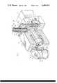
FIG. 1 is a general cross-sectional perspective view of a roller entry guide; and
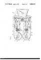
FIG. 2 is a sectional plan view, of the roller entry guide shown in FIG. 1.
Referring now to the drawings, aroller entry guide 10 has a body member generally designated 12 which is provided with abore 14 that extends along a longitudinal axis of theguide 10 from arear face 16 to afront face 18 of thebody member 12. Aninlet chute 20 having athroat 22 of progressively reducing cross-section is held within thebore 14.
Located inchannels roller assemblies 28 each of which comprises anarm 30 carrying aroller 32. Therollers 32 are mounted onvertical spindles 34 at respectiveforward ends 36 of thearms 30, and are provided with conventional bearing assemblies for rotation about a vertical axis.
Thearms 30 are pivotally supported in the body bypins 39, mounted approximately mid-way on the arms. These pins are mounted at their ends in respective vertically extendingbores 40 on either side of thebody member 12 so that they are rotatable about respective vertical pivot axes.
Springs 38 is provided between thearms 30 and thebody member 12 adjacent to the rollers, to bias thearms 30 away from thebody 12.
At therear ends 41 of thearms buttons 45 are provided which project inwardly toward the longitudinal axis. Located between thesebuttons 45 and thebody member 12, are taperedportions 53 of a pair oflegs 54 which are part of ayoke 42. One side 55 of each of thesetapered portions 53 reacts against the body member and theother side 56 is inclined. The upper portions of the legs are connected by acentral portion 44 of the yoke which is mounted on the body by a threaded assembly 46. This threaded assembly has apin 48 mounted on thebody member 12 and a threadedsleeve 50 rotatably mounted on the outside of thepin 48. The upper end of thepin 48 is provided with aplug 52 and the upper end of the sleeve is provided with anadjustment surface 58, so that the sleeve can be rotated. A lock nut 57 is also provided on the sleeve at the top of thecentral portion 44.
The operation of the device will now be described with reference to FIGS. 1 and 2. Adjustment of the spacing between therollers 32 is achieved by unscrewing the lock nut 57 and turning theadjustment surface 58 to rotate the threadedsleeve 50. Theyoke 42 is prevented from rotating by thebody 12 and is therefore moved in the vertical direction. When theyoke 42 is moved downwardly, theinclined portion 56 is moved downwardly past thebuttons 45 causing thearms 30 to rotate about their respective vertical pivot axes. Therollers 32 are thereby moved simultaneously towards the longitudinal axis against the bias of thesprings 38. When theyoke 42 is moved upwardly, theinclined portion 56 is moved upwardly past thebuttons 45 causing thearms 30 to rotate about their respective pivot axes, and move the rollers simultaneously away from the longitudinal axis. In this way small adjustment may be made whilst maintaining the rollers centered on the axis.
Claims (6)
1. A roller entry guide to guide material along a longitudinal axis, said guide comprising:
a body;
a pair of generally parallel roller assemblies pivotally mounted on said body for rotation about a vertical axis, each of said roller assemblies being located on an opposite side of said longitudinal axis to define a passageway for material moving along said axis and including at least one roller rotatably attached thereto;
a yoke acting between the roller assemblies and said body, said yoke having a central portion with a pair of legs, one of said legs being disposed at each end of said central portion, said legs having tapered portions at the ends thereof which are operable on respective roller assemblies said legs being supported by said body; and
adjustment means operable on said yoke to raise or lower said yoke to induce conjoint rotation of said roller assemblies about a vertical axis, thereby causing said rollers to move simultaneously and to equal and opposite distances towards or away from said longitudinal axis.
2. The roller entry guide as claimed in claim 1, wherein each of said roller assemblies includes an arm pivotally mounted on said body for rotation about an axis normal to said longitudinal axis, and a roller rotatably mounted on one end of said arm for rotation about an axis parallel to and spaced from said normal axis.
3. A roller entry guide as claimed in claim 2, wherein said arms each include a button at another end thereof which projects towards the longitudinal axis, said tapered portions of said legs being slidably engageable with respective buttons.
4. A roller entry guide as claimed in claim 1, wherein said adjustment means comprises a pin mounted on said body and passing through said yoke, with a threaded sleeve rotatably mounted thereon, said threaded sleeve having a lock nut mounted thereon adjacent to said yoke and an adjustment surface at an upper end thereof said yoke being raised or lowered upon rotation of said sleeve by said adjustment surface.
5. A roller entry guide as claimed in claim 2 including biasing means located between each of said arms and said body to restrain the arms in their adjusted position.
6. A roller entry guide as claimed in claim 2 wherein said roller assemblies are pivotally supported in the body pins located generally mid-way on said arms.
Priority Applications (1)
| Application Number | Priority Date | Filing Date | Title |
|---|---|---|---|
| US06/785,719US4680953A (en) | 1985-10-09 | 1985-10-09 | Roller entry guide relating to a rod mill |
Applications Claiming Priority (1)
| Application Number | Priority Date | Filing Date | Title |
|---|---|---|---|
| US06/785,719US4680953A (en) | 1985-10-09 | 1985-10-09 | Roller entry guide relating to a rod mill |
Publications (1)
| Publication Number | Publication Date |
|---|---|
| US4680953Atrue US4680953A (en) | 1987-07-21 |
Family
ID=25136414
Family Applications (1)
| Application Number | Title | Priority Date | Filing Date |
|---|---|---|---|
| US06/785,719Expired - LifetimeUS4680953A (en) | 1985-10-09 | 1985-10-09 | Roller entry guide relating to a rod mill |
Country Status (1)
| Country | Link |
|---|---|
| US (1) | US4680953A (en) |
Cited By (12)
| Publication number | Priority date | Publication date | Assignee | Title |
|---|---|---|---|---|
| EP1033184A1 (en)* | 1997-11-10 | 2000-09-06 | Mario Fabris | Triple roller entry guide |
| WO2000066288A1 (en)* | 1999-05-03 | 2000-11-09 | Morgan Construction Company | Adjustable monitoring guide |
| US6227025B1 (en)* | 1999-03-11 | 2001-05-08 | Kotobuki Sangyo Kabushiki Kaisha | Rolling method using rolling guide |
| US6237387B1 (en)* | 1999-04-28 | 2001-05-29 | Kotobuki Sangyo Kabushiki Kaisha | Entrance roller guide apparatus |
| RU2221658C2 (en)* | 2001-11-02 | 2004-01-20 | Республиканское Унитарное Предприятие "Белорусский Металлургический Завод" | Roller guide with apparatus for controlling roller rotation |
| US20040244678A1 (en)* | 2001-09-06 | 2004-12-09 | Otmar Palzer | Guide roller system for guiding the rods between the finishing stands of rod rolling mills |
| US8927748B2 (en) | 2011-08-12 | 2015-01-06 | Sigma-Aldrich Co. Llc | Alkyl-substituted allyl carbonyl metal complexes and use thereof for preparing dielectric thin films |
| CN104438367A (en)* | 2014-12-01 | 2015-03-25 | 江苏永钢集团有限公司 | Guiding-guarding opening degree fixing device |
| US9028917B2 (en) | 2009-08-07 | 2015-05-12 | Sigma-Aldrich Co. Llc | High molecular weight alkyl-allyl cobalttricarbonyl complexes and use thereof for preparing dielectric thin films |
| CN109731926A (en)* | 2019-01-23 | 2019-05-10 | 合肥市百胜科技发展股份有限公司 | Guide and guard |
| US10702901B2 (en)* | 2017-01-11 | 2020-07-07 | Aktiebolaget Skf | Guide roller |
| JP7598142B2 (en) | 2021-03-31 | 2024-12-11 | 寿産業株式会社 | Roller guide |
Citations (3)
| Publication number | Priority date | Publication date | Assignee | Title |
|---|---|---|---|---|
| GB811623A (en)* | 1956-11-19 | 1959-04-08 | Moeller & Neumann Gmbh | Roller guide for rolling mills |
| JPS4627850Y1 (en)* | 1969-11-06 | 1971-09-27 | ||
| US4039107A (en)* | 1975-11-12 | 1977-08-02 | Boley Robert E | Roller entry guide having improved guide insert and roller adjustment means |
- 1985
- 1985-10-09USUS06/785,719patent/US4680953A/ennot_activeExpired - Lifetime
Patent Citations (3)
| Publication number | Priority date | Publication date | Assignee | Title |
|---|---|---|---|---|
| GB811623A (en)* | 1956-11-19 | 1959-04-08 | Moeller & Neumann Gmbh | Roller guide for rolling mills |
| JPS4627850Y1 (en)* | 1969-11-06 | 1971-09-27 | ||
| US4039107A (en)* | 1975-11-12 | 1977-08-02 | Boley Robert E | Roller entry guide having improved guide insert and roller adjustment means |
Cited By (16)
| Publication number | Priority date | Publication date | Assignee | Title |
|---|---|---|---|---|
| EP1033184A1 (en)* | 1997-11-10 | 2000-09-06 | Mario Fabris | Triple roller entry guide |
| US6227025B1 (en)* | 1999-03-11 | 2001-05-08 | Kotobuki Sangyo Kabushiki Kaisha | Rolling method using rolling guide |
| US6237387B1 (en)* | 1999-04-28 | 2001-05-29 | Kotobuki Sangyo Kabushiki Kaisha | Entrance roller guide apparatus |
| WO2000066288A1 (en)* | 1999-05-03 | 2000-11-09 | Morgan Construction Company | Adjustable monitoring guide |
| US6209378B1 (en)* | 1999-05-03 | 2001-04-03 | Morgan Construction Company | Adjustable monitoring guide |
| AU764476B2 (en)* | 1999-05-03 | 2003-08-21 | Morgan Construction Company | Adjustable monitoring guide |
| US7062946B2 (en)* | 2001-09-06 | 2006-06-20 | Sms Meer Gmbh | Guide roller system for guiding the rods between the finishing stands of rod rolling mills |
| US20040244678A1 (en)* | 2001-09-06 | 2004-12-09 | Otmar Palzer | Guide roller system for guiding the rods between the finishing stands of rod rolling mills |
| RU2221658C2 (en)* | 2001-11-02 | 2004-01-20 | Республиканское Унитарное Предприятие "Белорусский Металлургический Завод" | Roller guide with apparatus for controlling roller rotation |
| US9028917B2 (en) | 2009-08-07 | 2015-05-12 | Sigma-Aldrich Co. Llc | High molecular weight alkyl-allyl cobalttricarbonyl complexes and use thereof for preparing dielectric thin films |
| US8927748B2 (en) | 2011-08-12 | 2015-01-06 | Sigma-Aldrich Co. Llc | Alkyl-substituted allyl carbonyl metal complexes and use thereof for preparing dielectric thin films |
| CN104438367A (en)* | 2014-12-01 | 2015-03-25 | 江苏永钢集团有限公司 | Guiding-guarding opening degree fixing device |
| US10702901B2 (en)* | 2017-01-11 | 2020-07-07 | Aktiebolaget Skf | Guide roller |
| CN109731926A (en)* | 2019-01-23 | 2019-05-10 | 合肥市百胜科技发展股份有限公司 | Guide and guard |
| CN109731926B (en)* | 2019-01-23 | 2024-03-22 | 合肥市百胜科技发展股份有限公司 | Guide and defend |
| JP7598142B2 (en) | 2021-03-31 | 2024-12-11 | 寿産業株式会社 | Roller guide |
Similar Documents
| Publication | Publication Date | Title |
|---|---|---|
| US4680953A (en) | Roller entry guide relating to a rod mill | |
| US5676010A (en) | Wire straightening device | |
| DE2600497A1 (en) | FEELING PEN FOR DETERMINING THE CONTOUR OF FACETED GROOVES IN EYEGLASSES | |
| US4738005A (en) | Adjusting device for operating elements of cards or carding rollers | |
| DE19960649B4 (en) | Device for correcting the lateral position of a printing material web in a web-fed rotary printing press | |
| JPH0796758B2 (en) | Roll gap protector | |
| US5937689A (en) | Triple roller entry guide | |
| JPH01254311A (en) | Device for guiding rolling material between roll for roll stand | |
| EP0908313B1 (en) | Machine for lettering of eggs | |
| EP0143523B1 (en) | Roller entry guide | |
| US4700875A (en) | Roller entry guide | |
| DE2559893C2 (en) | Device for controlling the translational relative movements during electrical discharge machining | |
| US7062946B2 (en) | Guide roller system for guiding the rods between the finishing stands of rod rolling mills | |
| DE3872089T2 (en) | UNIT FOR HANGING A RINGBANK. | |
| DE19850678C1 (en) | Double acting drop brake for shelving lift has bracket on guide rail with active and passive brake pads | |
| US3998083A (en) | Straightening apparatus | |
| JPH09295049A (en) | Guide roller of straightening machine | |
| JP2617976B2 (en) | Feed roll device | |
| DE3809449C1 (en) | ||
| CA2253089C (en) | Triple roller entry guide | |
| DE2166990C2 (en) | Horizontal band saw machine | |
| US2890647A (en) | Roller mill bearing | |
| WO2002030587A1 (en) | Strip coiler entry side guides | |
| DE1081808B (en) | Drive for high-speed ring spinning or twisting spindles | |
| KR200285932Y1 (en) | Rolling material prevention device of rolling mill |
Legal Events
| Date | Code | Title | Description |
|---|---|---|---|
| AS | Assignment | Owner name:FABRIS INDUSTRIAL MANUFACTURING LIMITED, 1216 SOUT Free format text:ASSIGNMENT OF ASSIGNORS INTEREST.;ASSIGNOR:FABRIS, MARIO;REEL/FRAME:004467/0571 Effective date:19850930 | |
| STCF | Information on status: patent grant | Free format text:PATENTED CASE | |
| FEPP | Fee payment procedure | Free format text:PAYOR NUMBER ASSIGNED (ORIGINAL EVENT CODE: ASPN); ENTITY STATUS OF PATENT OWNER: SMALL ENTITY | |
| FPAY | Fee payment | Year of fee payment:4 | |
| FPAY | Fee payment | Year of fee payment:8 | |
| AS | Assignment | Owner name:MARIO FABRIS, ONTARIO Free format text:ASSIGNMENT OF ASSIGNORS INTEREST;ASSIGNOR:FABRIS INC.;REEL/FRAME:009214/0654 Effective date:19980225 | |
| FPAY | Fee payment | Year of fee payment:12 |