US4680741A - Method and apparatus for seismic exploration using non-linear sweeps - Google Patents
Method and apparatus for seismic exploration using non-linear sweepsDownload PDFInfo
- Publication number
- US4680741A US4680741AUS06/913,558US91355886AUS4680741AUS 4680741 AUS4680741 AUS 4680741AUS 91355886 AUS91355886 AUS 91355886AUS 4680741 AUS4680741 AUS 4680741A
- Authority
- US
- United States
- Prior art keywords
- sweep
- frequency
- time
- rate
- change
- Prior art date
- Legal status (The legal status is an assumption and is not a legal conclusion. Google has not performed a legal analysis and makes no representation as to the accuracy of the status listed.)
- Expired - Lifetime
Links
Images


Classifications
- G—PHYSICS
- G01—MEASURING; TESTING
- G01V—GEOPHYSICS; GRAVITATIONAL MEASUREMENTS; DETECTING MASSES OR OBJECTS; TAGS
- G01V1/00—Seismology; Seismic or acoustic prospecting or detecting
- G01V1/02—Generating seismic energy
- G01V1/04—Details
Definitions
- the present inventionrelates to method and apparatus for seismic exploration, and, more particularly, to providing a nonlinear sweep signal to a vibrator in a seismic system.
- seismic wavesare commonly used to probe the earth's crust as a means of determining the type and location of subsurface formations.
- the earth's crustcan be considered a transmission medium or filter whose characteristics are to be determined by passing seismic waves through that medium.
- seismic waves or impulsesare generated at a point at or near the earth's surface, and the compressional mode of these waves is reflected from subsurface acoustic impedance boundaries and detected by arrays of seismic detectors located at the earth's crust.
- the seismic detectorsconvert the received waves into electrical signals which are sensed and recorded in a form which permits analysis. Skilled interpreters can discern from such an analysis the shape and depth of subsurface reflection boundaries and the likelihood of finding an accumulation of minerals, such as oil and gas.
- Another source of seismic energyis a vibrator which, when energized, imparts relatively low level energy signals into the earth's crust.
- the impartation of energy with vibrator devicesis for a preselected energization interval, and data are recorded during the energization interval and a subsequent "listening" interval.
- the vibratorOften it is desirable for the vibrator to impart energies of varying frequencies into the earth's crust during the energization interval.
- energy at a starting frequencyis first imparted into the earth, and the frequency of energization changes over the energization interval at some rate until the stopping frequency is reached at the end of the interval.
- the difference between the starting and stopping frequencies of the sweep generatoris known as the range of the sweep, and the length of time in which the generator has to sweep through those frequencies is known as the sweep time.
- Vibratorstypically employ a sweep generator, and the output of the sweep generator is coupled to the input of the vibrating type device.
- the output of the sweep generatordictates the manner in which the frequency of the energization signal which is imparted into the earth's crust varies as a function of time.
- Nonlinear sweep signalshave been suggested but have not achieved acceptance by the industry due to poor performance.
- a method of seismic explorationwherein an optimal nonlinear sweep signal is presented to the source of vibrating seismic energy.
- At least one array of seismic detectorsis established at a location on the earth's surface and at least one vibrator is also established on the earth's surface.
- the vibratorincludes a sweep generator, which generates an output signal.
- the output signal of the sweep generatoris nonlinear, and preferably, varies as a function of time during the sweep time as follows: ##EQU1## where: t is the instantaneous value of time during the sweep in seconds;
- F 0is the frequency at which the sweep starts in Hz
- Ris the range of frequencies over which the sweep varies during the sweep time
- a 0is the initial rate of change of frequency with respect to time
- Cis the logarithm to the base 10 of the ratio of the response at high frequency to the response at low frequency. C is chosen to provide compensation for any attenuation which exists to a particular impedance boundary over the range R.
- the starting frequency of the sweepis 10 Hz
- the stopping frequency of the sweepis 110 Hz
- the sweep timeis 10 seconds
- the attenuation of the earthis a total of 20 db
- a method of generating an output signal of a predetermined shapecomprises dividing the sweep time of the output signal into a plurality of preselected time intervals. The method also comprises calculating the rate of change of the frequency of the output signal for each time interval to realize said predetermined shape based on the range of the sweep, the sweep time, the starting frequency of the sweep and the predetermined shape of the output signal. The signals representative of the rate of change of the output frequency are then fed to a frequency generator, which generates the output signal.
- FIG. 1is a pictorial diagram which illustrates component parts of a seismic exploration system.
- FIG. 2is a block diagram of some of the component parts of the vibrator depicted in FIG. 1.
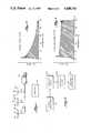
- FIG. 3is a graphical illustration of an experimental frequency response using a linear sweep.
- FIG. 4is a graphical illustration of an experimental frequency response using a nonlinear sweep in accordance with the present invention.
- FIG. 5is an electrical schematic in block diagram form of apparatus for generating a nonlinear sweep signal.
- FIG. 6is an electrical schematic in block diagram form of a programmer apparatus.
- FIG. 7is a more detailed electrical schematic of portions of the circuitry illustrated in FIGS. 5 and 6.
- the systemcomprises a plurality of seismic arrays 101.
- Each seismic array 101contains a plurality of seismic detectors 102.
- the seismic arrays 101are preferably located at regularly spaced intervals along the earth's surface.
- the system illustrated in FIG. 1also includes recording cable 104, which is preferably a multi-pair of cable.
- recording cable 104which is preferably a multi-pair of cable.
- a pair of wires 103is "taken out" of cable 104 and is connected to the output of each seismic array 101. Electrical signals generated by the seismic detectors 102 in seismic arrays 101 are conveyed via the multi pair of cable 104 to recording truck 105, where appropriate field recording of the signals takes place.
- the system illustrated in FIG. 1also includes a source of seismic energy, which is shown as vibrator 107.
- vibrator 107Periodically, vibrator 107 imparts low-level seismic waves into the earth.
- the seismic arrays 101produce electrical signals in response to the reflected portions of the seismic waves, and the electrical signals are then conveyed to recording truck 105.
- Vibrator 107includes sweep generator 201, hydraulic valve 202, hydraulic piston 203 and vibrator base plate 204.
- the output signal from sweep generator 201is fed to hydraulic valve 202, which is preferably a solenoid-actuated valve.
- hydraulic valve 202controls the movement of hydraulic piston 203, which in turn drives the vibrator base plate 204.
- Vibrator base plate 204is in contact with the earth and imparts seismic energy into the earth's crust responsive to the movement of hydraulic piston 203.
- vibrator unitsIn many applications where vibrator units are utilized as the source of seismic energy, energy is input into the earth during an energization interval of time, and seismic data are recorded during the energization interval and for a listening interval following the energization interval.
- the frequency of the input energyis often varied over a range of preselected values.
- vibrator 107may input energy at a frequency of 10 Hz at the start of the energization interval, and may change the input frequency at some preselected rate over the energization interval.
- the difference between the stopping and starting frequenciesis known as the range of the sweep, and the length of the energization interval is known as the sweep time.
- sweep generator 201is designed to provide a nonlinear signal to.hydraulic valve 202 to provide nonlinear control of the frequencies inputted into the earth by vibrator 107, as vibrator 107 sweeps through the range of frequencies which are to be input at nay given time.
- the frequency of the output signal from sweep generator 201varies as a function of time during the sweep is as follows: ##EQU2## where: t is the instantaneous value of time during the sweep in seconds;
- F 0is the frequency at which the sweep starts in Hz
- Ris the range of frequencies over which the sweep varies during the sweep time
- a 0is the initial rate of change of frequency with respect to time
- Cis the logarithm to the base 10 of the ratio of the response at high frequency to the response at low frequency. We have discovered that the value of C may be chosen to provide compensation for any attenuation which exists to a particular acoustic impedance boundary over the range R.
- the frequency of the signals inputted into the earthare to vary between 10 Hz and 110 Hz over a sweep time of 10 seconds and assuming that the attenuation of the earth is a total of 20 db between 10 Hz and 110 Hz
- the frequency of the output signal from sweep generator 201which will exactly compensate for this attenuation, varies over the sweep time as follows:
- apparatusfor generating a nonlinear signal at the output of a sweep generator.
- such apparatusincludes nonlinear range generator 501, frequency generator 502 and sine function generator 503.
- Nonlinear range generator 501inputs signals representative of the rate of change which is required in the frequency of the SWEEP OUT signal. The rate of change of frequency signals are provided at preselected time intervals during the sweep.
- Frequency generator 502responds to the rate of change in frequency signals to produce output signals representative of the new frequency.
- Sine function generator 503converts the digital output of frequency generator 502 to an analog signal of the desired frequency at its output (SWEEP OUT).
- nonlinear range generator 501provides rate of change of frequency signals to frequency generator 502.
- relatively smooth transistions in frequency of SWEEP OUTare realized.
- prior attempts to provide a nonlinear outputhave attempted to provide change in frequency information to the sweep generator. With this latter approach, smooth transitions in output frequency have not been achieved.
- Programmer 600includes processor 602 and front panel control 601.
- the values of the starting frequency of the sweep, the range of the sweep, the sweep time, and the desired shape of the nonlinear outputare programmed in front panel control 601.
- Processor 602reads this programmed information.
- Processor 602also divides the sweep time into small intervals of time, and in a preferred embodiment, these intervals of time are four milliseconds. For each four millisecond interval, processor 602 calculates the rate of change of frequency required to realize the desired output of the sweep generator.
- non-volatile storage device 603which is preferably an electrically erasable programmable read only memory (EEPROM) card.
- EEPROMelectrically erasable programmable read only memory
- the EEPROMs of non-volatile memory storage device 603has a storage capacity of 4,096, eight-bit words.
- the contents of non-volatile storage device 603thus contains the information necessary for the SWEEP OUT signal to move from the starting frequency to the stopping frequency in the sweep time according to the nonlinear function desired.
- the non-linear function realizedis as set forth in expression (1) above.
- Nonlinear range generator 501includes storage 603 and a 2:1 multiplexer 702 coupled to two range ROMs 704, 706, each of which is cooperatively coupled to a parallel to serial register 708, 709.
- the NONLINEAR SWEEP SIGNAL from nonlinear range generator 501is input to sweep generator counters 710, 711, 712 of frequency generator 502.
- a 524.288 kilohertz signalis input to binary rate multiplier 718, each of which is coupled to a sweep generator counter 710, 711, or 712.
- Binary rate multiplier 714is coupled to ROM clock 719 which is coupled to ROM drivers 721 and 720.
- ROM drivers 721 and 720are coupled to ROMs 722 and 724 which are then coupled to sine function generator 503.
- a DAC 726converts the digital output of frequency generator 502 to an analog signal which is then amplified to the desired SWEEP OUT level.
Landscapes
- Engineering & Computer Science (AREA)
- Remote Sensing (AREA)
- Physics & Mathematics (AREA)
- Life Sciences & Earth Sciences (AREA)
- Acoustics & Sound (AREA)
- Environmental & Geological Engineering (AREA)
- Geology (AREA)
- General Life Sciences & Earth Sciences (AREA)
- General Physics & Mathematics (AREA)
- Geophysics (AREA)
- Geophysics And Detection Of Objects (AREA)
Abstract
Description
10+43.43 ln (0.9t+1).
10+43.43 ln [0.9t+1].
Claims (2)
Priority Applications (1)
| Application Number | Priority Date | Filing Date | Title |
|---|---|---|---|
| US06/913,558US4680741A (en) | 1981-10-13 | 1986-09-29 | Method and apparatus for seismic exploration using non-linear sweeps |
Applications Claiming Priority (2)
| Application Number | Priority Date | Filing Date | Title |
|---|---|---|---|
| US31082881A | 1981-10-13 | 1981-10-13 | |
| US06/913,558US4680741A (en) | 1981-10-13 | 1986-09-29 | Method and apparatus for seismic exploration using non-linear sweeps |
Related Parent Applications (1)
| Application Number | Title | Priority Date | Filing Date |
|---|---|---|---|
| US31082881AContinuation | 1981-10-13 | 1981-10-13 |
Publications (1)
| Publication Number | Publication Date |
|---|---|
| US4680741Atrue US4680741A (en) | 1987-07-14 |
Family
ID=26977607
Family Applications (1)
| Application Number | Title | Priority Date | Filing Date |
|---|---|---|---|
| US06/913,558Expired - LifetimeUS4680741A (en) | 1981-10-13 | 1986-09-29 | Method and apparatus for seismic exploration using non-linear sweeps |
Country Status (1)
| Country | Link |
|---|---|
| US (1) | US4680741A (en) |
Cited By (15)
| Publication number | Priority date | Publication date | Assignee | Title |
|---|---|---|---|---|
| US4758997A (en)* | 1986-08-25 | 1988-07-19 | Hydroacoustics Inc. | Method and apparatus for the generation and transmission of signals for echo location and other signaling purposes, particularly in geophysical exploration |
| US4766576A (en)* | 1984-04-02 | 1988-08-23 | Texas Instruments Incorporated | Seismic source vibrator having improved sweep generator |
| US5331607A (en)* | 1993-02-23 | 1994-07-19 | Roessler Dennis E | Sweep frequency vibrator |
| US5347494A (en)* | 1993-07-01 | 1994-09-13 | Exxon Production Research Company | Shaped-sweep technology |
| US5410517A (en)* | 1994-05-13 | 1995-04-25 | Exxon Production Research Company | Method for cascading sweeps for a seismic vibrator |
| RU2162607C2 (en)* | 1999-04-22 | 2001-01-27 | Объединенный институт физики Земли им. О.Ю. Шмидта РАН | Procedure of seismic microzoning |
| US20070136013A1 (en)* | 2005-12-09 | 2007-06-14 | William Premerlani | Methods and systems for measuring a rate of change of requency |
| US20080008040A1 (en)* | 2006-07-05 | 2008-01-10 | Martin Laycock | Seismic acquisition system |
| US20080246200A1 (en)* | 2005-11-08 | 2008-10-09 | Koninklijke Philips Electronics, N.V. | Vibration Isolation System and Method |
| US20090251994A1 (en)* | 2008-04-04 | 2009-10-08 | Ion Geophysical Corporation | Seismic vibrator array and methods of operation |
| US20110085416A1 (en)* | 2009-10-09 | 2011-04-14 | CGG Veritas | System and method for determining a frequency sweep for seismic analysis |
| RU2546753C1 (en)* | 2011-03-14 | 2015-04-10 | Джеко Текнолоджи Б.В. | Marine vibrator sweep |
| AU2013200589B2 (en)* | 2012-02-02 | 2015-07-02 | Sercel Sas | Sweep design for seismic sources |
| CN105425289A (en)* | 2015-10-29 | 2016-03-23 | 中国石油天然气集团公司 | Method and device of determining low frequency wave impedance |
| US9753163B2 (en) | 2012-01-12 | 2017-09-05 | Westerngeco L.L.C. | Simultaneous marine vibrators |
Citations (9)
| Publication number | Priority date | Publication date | Assignee | Title |
|---|---|---|---|---|
| US3739374A (en)* | 1971-08-27 | 1973-06-12 | Mandrel Industries | Digital sweep generator for generating analog signals |
| US3815704A (en)* | 1972-12-26 | 1974-06-11 | Texaco Inc | Method for determining optimum seismic pulse |
| US3886493A (en)* | 1973-05-07 | 1975-05-27 | Amoco Prod Co | Adaptive monofrequency pilot signals |
| US4004267A (en)* | 1972-11-28 | 1977-01-18 | Geosource Inc. | Discrete frequency seismic exploration using non uniform frequency spectra |
| US4168485A (en)* | 1974-08-12 | 1979-09-18 | Continental Oil Company | Simultaneous use of pseudo-random control signals in vibrational exploration methods |
| US4248324A (en)* | 1979-02-07 | 1981-02-03 | Exxon Production Research Company | Seismic vibrator and method for improving the output of a seismic vibrator |
| US4293935A (en)* | 1977-06-30 | 1981-10-06 | Societe Nationale Elf Aquitaine (Production) | Method of seismic exploration |
| US4326262A (en)* | 1978-10-16 | 1982-04-20 | Clement Alvin H | Universal signal generator and signal parameter comparator |
| US4493067A (en)* | 1981-04-13 | 1985-01-08 | Conoco Inc. | Seismic vibrator control system |
- 1986
- 1986-09-29USUS06/913,558patent/US4680741A/ennot_activeExpired - Lifetime
Patent Citations (9)
| Publication number | Priority date | Publication date | Assignee | Title |
|---|---|---|---|---|
| US3739374A (en)* | 1971-08-27 | 1973-06-12 | Mandrel Industries | Digital sweep generator for generating analog signals |
| US4004267A (en)* | 1972-11-28 | 1977-01-18 | Geosource Inc. | Discrete frequency seismic exploration using non uniform frequency spectra |
| US3815704A (en)* | 1972-12-26 | 1974-06-11 | Texaco Inc | Method for determining optimum seismic pulse |
| US3886493A (en)* | 1973-05-07 | 1975-05-27 | Amoco Prod Co | Adaptive monofrequency pilot signals |
| US4168485A (en)* | 1974-08-12 | 1979-09-18 | Continental Oil Company | Simultaneous use of pseudo-random control signals in vibrational exploration methods |
| US4293935A (en)* | 1977-06-30 | 1981-10-06 | Societe Nationale Elf Aquitaine (Production) | Method of seismic exploration |
| US4326262A (en)* | 1978-10-16 | 1982-04-20 | Clement Alvin H | Universal signal generator and signal parameter comparator |
| US4248324A (en)* | 1979-02-07 | 1981-02-03 | Exxon Production Research Company | Seismic vibrator and method for improving the output of a seismic vibrator |
| US4493067A (en)* | 1981-04-13 | 1985-01-08 | Conoco Inc. | Seismic vibrator control system |
Non-Patent Citations (10)
| Title |
|---|
| Advertising Brochure Texas Instruments Vibrator Contol System , 1980.* |
| Advertising Brochure--Texas Instruments "Vibrator Contol System", ©1980. |
| Advertisment Optimize Vibrator Operations with New III Vibrator Control system , printed in Geophysics, Jun. 1981 issue.* |
| Advertisment--"Optimize Vibrator Operations with New III Vibrator Control system", printed in Geophysics, Jun. 1981 issue. |
| Broding, "The Continuous Sweep Vibroseis Method", Offshore Technology Conference, 1970. |
| Broding, The Continuous Sweep Vibroseis Method , Offshore Technology Conference, 1970.* |
| Lerwill, "Seismic Sources on Land," pp. 115-141, Glide Science Publications, 1979. |
| Lerwill, Seismic Sources on Land, pp. 115 141, Glide Science Publications, 1979.* |
| Werner et al., "Combisweep--A Contribution to Sweep Techniques," European Association of Exploration Geophysicists, Jun., 1977. |
| Werner et al., Combisweep A Contribution to Sweep Techniques, European Association of Exploration Geophysicists, Jun., 1977.* |
Cited By (26)
| Publication number | Priority date | Publication date | Assignee | Title |
|---|---|---|---|---|
| US4766576A (en)* | 1984-04-02 | 1988-08-23 | Texas Instruments Incorporated | Seismic source vibrator having improved sweep generator |
| US4758997A (en)* | 1986-08-25 | 1988-07-19 | Hydroacoustics Inc. | Method and apparatus for the generation and transmission of signals for echo location and other signaling purposes, particularly in geophysical exploration |
| US5331607A (en)* | 1993-02-23 | 1994-07-19 | Roessler Dennis E | Sweep frequency vibrator |
| US5347494A (en)* | 1993-07-01 | 1994-09-13 | Exxon Production Research Company | Shaped-sweep technology |
| AU672110B2 (en)* | 1993-07-01 | 1996-09-19 | Exxon Production Research Company | Shaped-sweep technology |
| US5410517A (en)* | 1994-05-13 | 1995-04-25 | Exxon Production Research Company | Method for cascading sweeps for a seismic vibrator |
| RU2162607C2 (en)* | 1999-04-22 | 2001-01-27 | Объединенный институт физики Земли им. О.Ю. Шмидта РАН | Procedure of seismic microzoning |
| US20080246200A1 (en)* | 2005-11-08 | 2008-10-09 | Koninklijke Philips Electronics, N.V. | Vibration Isolation System and Method |
| US20070136013A1 (en)* | 2005-12-09 | 2007-06-14 | William Premerlani | Methods and systems for measuring a rate of change of requency |
| US7328114B2 (en) | 2005-12-09 | 2008-02-05 | General Electric Company | Methods and systems for measuring a rate of change of frequency |
| US8797827B2 (en) | 2006-07-05 | 2014-08-05 | Westerngeco L.L.C. | Seismic acquisition system |
| US7885143B2 (en)* | 2006-07-05 | 2011-02-08 | Westerngeco L.L.C. | Seismic acquisition system |
| US20080008040A1 (en)* | 2006-07-05 | 2008-01-10 | Martin Laycock | Seismic acquisition system |
| US20110090759A1 (en)* | 2006-07-05 | 2011-04-21 | Martin Laycock | Seismic Acquisition System |
| US20090251994A1 (en)* | 2008-04-04 | 2009-10-08 | Ion Geophysical Corporation | Seismic vibrator array and methods of operation |
| US7881160B2 (en)* | 2008-04-04 | 2011-02-01 | Ion Geophysical Corporation | Seismic vibrator array and methods of operation |
| US8559275B2 (en) | 2009-10-09 | 2013-10-15 | CGG Veritas | System and method for determining a frequency sweep for seismic analysis |
| US8274862B2 (en) | 2009-10-09 | 2012-09-25 | CGG Veritas | System and method for determining a frequency sweep for seismic analysis |
| US20110085416A1 (en)* | 2009-10-09 | 2011-04-14 | CGG Veritas | System and method for determining a frequency sweep for seismic analysis |
| US9535178B2 (en) | 2009-10-09 | 2017-01-03 | CGG Veritas | System and method for determining a frequency sweep for seismic analysis |
| US10042064B2 (en) | 2009-10-09 | 2018-08-07 | Cgg Services Sas | System and method for determining a frequency sweep for seismic analysis |
| RU2546753C1 (en)* | 2011-03-14 | 2015-04-10 | Джеко Текнолоджи Б.В. | Marine vibrator sweep |
| US9547097B2 (en) | 2011-03-14 | 2017-01-17 | Westerngeco L.L.C. | Marine vibrator sweeps |
| US9753163B2 (en) | 2012-01-12 | 2017-09-05 | Westerngeco L.L.C. | Simultaneous marine vibrators |
| AU2013200589B2 (en)* | 2012-02-02 | 2015-07-02 | Sercel Sas | Sweep design for seismic sources |
| CN105425289A (en)* | 2015-10-29 | 2016-03-23 | 中国石油天然气集团公司 | Method and device of determining low frequency wave impedance |
Similar Documents
| Publication | Publication Date | Title |
|---|---|---|
| US4680741A (en) | Method and apparatus for seismic exploration using non-linear sweeps | |
| US4598392A (en) | Vibratory signal sweep seismic prospecting method and apparatus | |
| US5790473A (en) | High fidelity vibratory source seismic method for use in vertical seismic profile data gathering with a plurality of vibratory seismic energy sources | |
| US5715213A (en) | High fidelity vibratory source seismic method using a plurality of vibrator sources | |
| CA2277119C (en) | Seismic data acquisition and processing using non-linear distortion in a groundforce signal | |
| US3895343A (en) | Apparatus for producing adaptive pilot signals | |
| US5550786A (en) | High fidelity vibratory source seismic method | |
| RU2309436C2 (en) | Data processing method | |
| US5703833A (en) | One step inversion/separation scheme using a plurality of vibrator sources | |
| US2794965A (en) | Statistical interpretation of seismograms | |
| US5724308A (en) | Programmable acoustic borehole logging | |
| US4512001A (en) | Method and apparatus for seismic exploration using nonlinear sweeps | |
| US3886493A (en) | Adaptive monofrequency pilot signals | |
| US4740928A (en) | Sonic logging system | |
| US4561074A (en) | Computationally efficient weighting and vertical stacking methods and apparatus for improving signal-to-noise ratio of seismic data | |
| US4348749A (en) | Phase correcting seismic traces | |
| US4819214A (en) | Sonic logging system | |
| US4608673A (en) | Minimum phase bandpass filtering of seismic signals | |
| US6201764B1 (en) | Apparatus and method for correcting for capacitance variations in hydrophones | |
| EP0288154A2 (en) | Method for estimating shear wave reflection data from acquired compressional wave reflection data | |
| US3815704A (en) | Method for determining optimum seismic pulse | |
| US4069470A (en) | Use of periodic signals for continuous wave seismic prospecting | |
| US4034333A (en) | Method of reducing monochromatic interference in continuous wave seismic prospecting | |
| CA1187595A (en) | Method and apparatus for seismic exploration using non-linear sweeps | |
| US4577297A (en) | Method for enhancing recorded marine seismic reflection signals having undulating water bottom distortions |
Legal Events
| Date | Code | Title | Description |
|---|---|---|---|
| STCF | Information on status: patent grant | Free format text:PATENTED CASE | |
| AS | Assignment | Owner name:G & H MANAGEMENT COMPANY Free format text:CHANGE OF NAME;ASSIGNOR:GEOSOURCE, INC.;REEL/FRAME:005252/0167 Effective date:19881129 Owner name:HALLIBURTON GEOPHYSICAL SERVICES, INC., TEXAS Free format text:ASSIGNMENT OF ASSIGNORS INTEREST.;ASSIGNOR:G & H MANAGEMENT COMPANY;REEL/FRAME:005252/0162 Effective date:19890918 | |
| FEPP | Fee payment procedure | Free format text:PAYOR NUMBER ASSIGNED (ORIGINAL EVENT CODE: ASPN); ENTITY STATUS OF PATENT OWNER: LARGE ENTITY | |
| FPAY | Fee payment | Year of fee payment:4 | |
| FEPP | Fee payment procedure | Free format text:PAYER NUMBER DE-ASSIGNED (ORIGINAL EVENT CODE: RMPN); ENTITY STATUS OF PATENT OWNER: LARGE ENTITY Free format text:PAYOR NUMBER ASSIGNED (ORIGINAL EVENT CODE: ASPN); ENTITY STATUS OF PATENT OWNER: LARGE ENTITY | |
| AS | Assignment | Owner name:HALLIBURTON COMPANY, OKLAHOMA Free format text:MERGER;ASSIGNOR:HALLIBURTON GEOPHYSICAL SERVICES, INC.;REEL/FRAME:006777/0052 Effective date:19931110 | |
| AS | Assignment | Owner name:WESTERN ATLAS INTERNATIONAL, INC., TEXAS Free format text:ASSIGNMENT OF ASSIGNORS INTEREST;ASSIGNOR:HALLIBURTON COMPANY;REEL/FRAME:006970/0236 Effective date:19940321 | |
| FPAY | Fee payment | Year of fee payment:8 | |
| AS | Assignment | Owner name:I/O EXPLORATION PRODUCTS, INC., TEXAS Free format text:ASSIGNMENT OF ASSIGNORS INTEREST;ASSIGNOR:WESTERN ATLAS INTERNATIONAL, INC.;REEL/FRAME:007644/0138 Effective date:19950630 | |
| AS | Assignment | Owner name:I/O EXPLORATION PRODUCTS (U.S.A), INC., TEXAS Free format text:CORRECTED ASSIGNMENT;ASSIGNOR:WESTERN ATLAS INTERNATIONAL, INC.;REEL/FRAME:007815/0841 Effective date:19950630 | |
| AS | Assignment | Owner name:INPUT/OUTPUT, INC., TEXAS Free format text:ASSIGNMENT OF ASSIGNORS INTEREST;ASSIGNOR:I/O EXPLORATION PRODUCTS (U.S.A.), INC.;REEL/FRAME:009245/0506 Effective date:19980212 | |
| FPAY | Fee payment | Year of fee payment:12 | |
| REMI | Maintenance fee reminder mailed |