US4680167A - Controlled atmosphere oven - Google Patents
Controlled atmosphere ovenDownload PDFInfo
- Publication number
- US4680167A US4680167AUS06/823,637US82363786AUS4680167AUS 4680167 AUS4680167 AUS 4680167AUS 82363786 AUS82363786 AUS 82363786AUS 4680167 AUS4680167 AUS 4680167A
- Authority
- US
- United States
- Prior art keywords
- gas
- chamber
- oven
- preselected
- heating chamber
- Prior art date
- Legal status (The legal status is an assumption and is not a legal conclusion. Google has not performed a legal analysis and makes no representation as to the accuracy of the status listed.)
- Expired - Lifetime
Links
Images


Classifications
- G—PHYSICS
- G01—MEASURING; TESTING
- G01N—INVESTIGATING OR ANALYSING MATERIALS BY DETERMINING THEIR CHEMICAL OR PHYSICAL PROPERTIES
- G01N33/00—Investigating or analysing materials by specific methods not covered by groups G01N1/00 - G01N31/00
- G01N33/26—Oils; Viscous liquids; Paints; Inks
- G01N33/28—Oils, i.e. hydrocarbon liquids
- G—PHYSICS
- G01—MEASURING; TESTING
- G01N—INVESTIGATING OR ANALYSING MATERIALS BY DETERMINING THEIR CHEMICAL OR PHYSICAL PROPERTIES
- G01N31/00—Investigating or analysing non-biological materials by the use of the chemical methods specified in the subgroup; Apparatus specially adapted for such methods
- G01N31/12—Investigating or analysing non-biological materials by the use of the chemical methods specified in the subgroup; Apparatus specially adapted for such methods using combustion
Definitions
- the Conradson Carbon Residue testis designed to indicate the extent of coke that a petroleum product will form under thermal degradation conditions, such as might be encountered in distillation towers, heat exchangers, and reactors. Since its inception, the CCR test has been applied to characterize a multitude of petroleum products and is currently defined by ASTM D 189-76 and IP 13/66.
- the CCR testis generally slow, lacks precision, and requires the utilization of large samples (5-10 grams). Due to the utilization of an open flame and the resultant smoke, the CCR test is also hazardous and messy.
- Sample containershould be glass.
- the assignee of the present inventionbegan development of a single unit tester oven that would provide all the advantages of the new method.
- the development of the present inventionwas assisted by the coincidental market introduction of a programmable controller by the Barber-Colman Co., Model 570.
- the invention ovenmay utilize any one of several possible heat control means and is designed to achieve any type of small scale batch heating of liquids or solids in an ambient pressure gas atmosphere.
- the present inventionachieves the advantages of Noels' new carbon residue testing method by providing an oven wherein a petroleum product may be heated in a preselected gas atmosphere.
- the ovencomprises an inner heating chamber having a cylindrical wall with a plurality of purge gas inlet ports therethrough near a top opening thereof and a bottom floor having a gas outlet port therethrough.
- the gas outlet portpermits the passage of purged oxygen and petroleum gas from the inner heating chamber into a gas exhaust tube during the purging phase and heating phase, respectively.
- the top opening of the inner heating chamberpermits the introduction of the petroleum product into the heating chamber, the top of which has a chamfered edge for receiving thereon a spherical gravity lid.
- the inner heating chamber and gas exhaust tubeare surrounded by an outer gas flow chamber and an ante chamber, respectively, the outer gas flow chamber being in communication with the ante chamber and having a plurality of concealed heater elements therein contiguous to the outer wall of the inner heating chamber.
- the heater elementsare continuously monitored by a programmable external controller which is in communication with a thermocouple protruding through the inner wall of the inner heating chamber, thereby permitting the product within the sealed inner heating chamber to be heated evenly at the rate and temperature desired.
- a glass vial containing the liquid or solid product to be heatedis introduced to the inner heating chamber and subsequently sealed therein by the gravity lid.
- a preselected inert or reactive purge gasis thereafter introduced to the ante chamber and flows therefrom into the outer gas flow chamber around the heater elements and into the inner heating chamber through the gas inlet ports.
- the lighter purge gasinitially purges the inner heating chamber of oxygen by gradually urging the denser air through the gas outlet port into the gas exhaust tube. After the inner heating chamber has been sufficiently purged, the product is heated at the rate and temperature specified by the controller program.
- the lighter purge gascontinues to purge the inner heating chamber of volatile vapor or gas by urging the denser vapor through the gas outlet port and gas exhaust tube.
- the cool purge gas entering the oven through the ante chambercools the gas outlet port resulting in a cooler surface that causes much of the vapor within the gas exhaust tube to condense therein.
- the condensed productis thereafter collected in a condensate trap connected to the bottom of the oven at the termination of the gas exhaust tube.
- the oxygen and process or product vapor that does not condenseis properly removed from the oven through an exhaust chimney which is connected to the gas exhaust tube and in communication with an exhaust hood.
- the original oven developed by Imperial Oil Ltd. for implementation of Noel's methodis the most relevant prior art known to applicant.
- the Imperial ovenpermits the introduction of various purge gases and does not expose the heater elements to the petroleum product. Nevertheless, it is readily distinguishable from the present invention.
- the Imperial Oil ovenis purged by forcing the purge gas through the heating chamber.
- the Imperial Oil ovenutilizes a bolted lid, thereby creating prime conditions for a subsequent explosion, and a crude, resistance furnace.
- the Imperial ovendoes not teach the use of a gravity seal lid, a programmable controller, or an outer gas flow chamber having heater elements therein and permitting the flow of purge gas therethrough.
- the Imperial Oil ovenutilizes hot and cool zones into which the test material is introduced by means of a movable tube which is inserted into the heating chamber.
- the thermocoupleis located on the tip of the movable tube in the center of the heating chamber rather than on the inner wall of the heating chamber, as disclosed in the present invention. Placement of the thermocouple away from the wall creates an important temperature variation and lag situation. The variation is due to the time lag between the heating and the time it takes for the thermocouple to sense the heat. The farther away from the heat source the sensor is, the more time lag will occur resulting in wide temperature cycling.
- the ovencomprises an inner heating chamber having a cylindrical wall with a plurality of purge gas inlet ports therethrough near a top opening thereof and a bottom floor having a central gas outlet port therethrough.
- the gas outlet portpermits the passage of oxygen and volatile product vapor from the inner heating chamber into a gas exhaust tube, which is connected to the bottom floor of the inner heating chamber.
- the gas exhaust tubepermits the flow of oxygen and product gas during the purging and heating phase, respectively, into an exhaust chimney or a condensate trap connected to the gas exhaust tube at the termination thereof.
- the top opening of the inner heating chamberis of sufficient size to permit the introduction of one or more glass vials containing the petroleum product into the inner heating chamber.
- the inner heating chamberhas a chamfered edge on the top thereof for receiving a spherical gravity lid thereon.
- the gravity lidprovides a tight seal for the inner heating chamber while maintaining an explosion safe environment therein.
- the inner heating chamber and gas exhaust tubeare surrounded by an outer gas flow chamber and an ante chamber, respectively, the outer gas flow chamber being in communication with the ante chamber.
- the outer gas flow chamberis sealed by a flange extending from the top of the inner heating chamber and has a plurality of concealed heater elements therein contiguous to the outer wall of the inner heating chamber.
- the resistance heater elementsare continuously monitored by an external programmable controller which is in communication with a thermocouple protruding through the inner wall of the inner heating chamber, thereby permitting the product sample within the sealed inner heating chamber to be heated evenly at the rate and temperature desired.
- the ovenis preferably housed within a cabinet having a thermal barrier therein separating the sensitive controller from the heating and purging elements of the invention.
- the preweighed distillable materialis introduced to the inner heating chamber and sealed therein by the spherical gravity lid.
- the inner heating chamberis thereafter purged of oxygen by the introduction of a preselected inert or reactive purge gas from an external gas supply.
- the purge gasenters the ante chamber through a purge gas feed line and flows therefrom into the outer gas flow chamber.
- the purge gascontinuously bathes the heater elements therein and subsequently flows therefrom into the top of the inner heating chamber through the purge gas inlet ports.
- the lighter purge gasgradually displaces the oxygen within the inner heating chamber by urging the denser oxygen outward through the gas outlet port and gas exhaust tube.
- the concealed heater elementsheat the walls of the inner heating chamber, thereby heating the distillable material therein.
- the preselected purge gascontinuously bathes the heater elements within the outer gas flow chamber and displaces the volatile product gas within the inner heating chamber. This is accomplished by the warm purge gas entering the top of the inner heating chamber continuously urging the denser product gas outward through the gas outlet port and gas exhaust tube.
- the purged product gasis caused to condense therein and be received by the condensate trap, thereby reducing unnecessary discharge of the hazardous gas.
- the oxygen and product gas which is not condensedflows outward from the system through an exhaust chimney connected to the gas exhaust tube intermediate to the ante chamber and condensate trap.
- heatingis discontinued, the inner heating chamber is cooled, the gravity lid is removed, and the test material is removed and reweighed to determine its weight loss.
- the cooling processis assisted by the continuous flow of purge gas around the heater elements into the inner heating chamber.
- the utilization of a programmable controllerpermits the controlled heating of the petroleum product and the controlled purging of the inner heating chamber at a high or low flow rate, the heating and purging being determined by the oven operator and the parameters of the test.
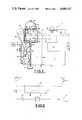
- FIG. 1is a schematic diagram of the oven heating system and gas flow system.
- FIG. 2is a schematic diagram of the oven gas flow system.
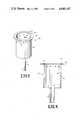
- FIG. 3is a perspective view of the inner heating chamber and gas exhaust tube.
- FIG. 4is a cross-sectional view of the inner heating chamber and gas exhaust tube.
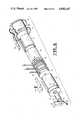
- FIG. 5is a cross-sectional view of the inner heating chamber, outer gas flow chamber, heater elements, gas exhaust tube, ante chamber, and gravity seal lid.
- FIG. 6is an exploded perspective view of the inner heating chamber, outer gas flow chamber, heater elements, gas exhaust tube, ante chamber, and heating chamber insulation.
- FIG. 7is a front plan view of the cabinet housing the invention oven.
- FIG. 8is a rear plan view of the cabinet housing the invention oven.
- FIG. 9is a perspective view of the oven cabinet and a transparent perspective view of the elements within the cabinet.
- FIG. 10is a bottom perspective view of the oven cabinet.
- FIG. 11is a graph illustrating a typical time and temperature process utilized in the invention oven.
- FIG. 12is a cross-sectional view of the preferred gravity seal lid utilized in the invention oven.
- the oven 10generally comprises a test chamber 11 housing the heating and gas flow portions of the system and a control chamber 13 housing the programmable controller 16.
- the controller 16monitors the continuous purging of inner heating chamber 48 by a preselected gas and the controlled heating of a distillable material 105 by heater elements 66.
- the oven 10is designed to heat a material 105 in a thoroughly purged, hot chamber at a constant or uniformly changing temperature.
- the controlled atmosphere within heating chamber 48is basically achieved by introducing a lighter, preselected gas into the top thereof and allowing the lighter gas to gradually displace the denser air or material vapor within the chamber 48.
- the various elements of the oven 10 described hereinbeloware preferably housed in a stainless steel cabinet 12 supported by a plurality of legs 14.
- the cabinet or outer housing 12comprises a front instrumentation panel 12a, a top panel 12b, a bottom panel 12c, a rear access panel 12d, and a pair of opposed side panels 12e.
- the front instrumentation panel 12acomprises the input unit of the microprocessor based controller 16, an ON/OFF power switch 18, a dual function purge gas pressure switch 20, a purge gas ON/OFF valve 22, and a purge gas pressure gauge 24.
- a removable insulated gravity seal lid 26having a lid handle 28 secured thereto and a lid rest 30 surrounding a plurality of control chamber outlet ports 32 which extend through top panel 12b.
- the bottom panel 12c of oven 10comprises a plurality of test chamber inlet ports 84 and a plurality of control chamber inlet ports 92.
- a removable glass condensate trap 34is secured to a condensate cap 35 which is connected to the bottom panel 12c of oven 10.
- the legs 14 connected to bottom panel 12cpermit access to the condensate trap 34 for purposes of trap removal and proper disposal of the material collected therein.
- the rear access panel 12d of oven 10preferably comprises a power supply line 36, fuses 38, purge gas inlet orifice 40, exhaust chimney 42, and a plurality of test chamber outlet ports 44.
- the power supply line 36is preferably in communication with an appropriate power supply, depending upon the option preselected by the user.
- the exhaust chimney 42preferably terminates in close proximity to an exhaust hood (not shown). Access to the internal elements of the oven 10 is obtained by the easy removal of the rear panel 12d.
- a thermal barrier 86separates the hot test chamber 11 which houses the inner heating chamber 48 from the control chamber 13 which houses the sensitive controller 16.
- the gravity seal lid 26may have either a spherical bottom 41 or a spherical seal 46 which covers the top opening 50 of a cylindrical inner heating chamber 48.
- Spherical bottom 41forms an integral unit with lid 26, as illustrated in FIG. 1, whereas spherical gravity seal 46 is a distinct solid element connected to lid 26 by a seal screw 27, as illustrated in FIG. 5 and FIG. 12.
- Spherical bottom 41 and spherical gravity seal 46may also have a pointed tip 47, as illustrated in FIG. 1, to assist in the removal of condensation therefrom.
- Spherical gravity seal 46is firmly secured to lid 26 by a moveable seal screw 27 which is inserted through the orifice 33 extending through steel plate 29 and an upper layer of ceramic insulation 31. Ceramic insulation layer 31 is appropriately connected to a lower layer of ceramic insulation 37.
- the moveable screw 27permits the solid stainless steel seal 46 to float when it rests on the chamfered edge 54 of inner heating chamber 48.
- the lower layer of ceramic insulation 37is connected to lid 26 by a plurality of screws 45 and rests upon flange 56 when lid 26 is placed on inner heating chamber 48.
- the spherical seal 46is suspended in a surrounding of ceramic insulation 31 and 37 with an air space 23 therebetween, thereby prohibiting condensation of vapor thereon.
- the head of moveable screw 27becomes flush with the steel plate 29, which allows even weight distribution over the relatively weak ceramic layer 31.
- the top of inner heating chamber 48has a chamfered or angled edge 54 of approximately 45° for receiving floating spherical seal 46 or spherical bottom 41, thereby providing a tight, gravity seal of the top opening 50 of inner heating chamber 48. Due to the simple gravity seal, the lid 26 can be removed quickly and easily, thereby permitting ready access to inner heating chamber 48.
- Cylindrical heating chamber 48preferably comprises an inner wall 48a and outer wall 48b, a bottom or floor 49, and an outer cylindrical flange 56 surrounding the top opening 50 thereof.
- Inner heating chamber 48is preferably constructed of stainless steel and preferably has a volume of approximately one liter. This size permits rapid and efficient heating and cooling and precise control thereof.
- the inner heating chamber 48is futher provided with a plurality of purge gas inlet ports 51 therethrough near top opening 50 thereof.
- the floor 49is also provided with a centrally located purge gas outlet port 52 which provides communication between the inner heating chamber 48 and a gas exhaust tube 62, which is welded or otherwise connected to the floor 49 at the location of the purge gas outlet port 52.
- inner heating chamber 48 and gas exhaust tube 62are surrounded by an outer gas flow chamber 58 and an ante chamber 60, respectively.
- Outer gas flow chamber 58is sealed on the top thereof by the flange 56 of inner heating chamber 48.
- An opening 61 in the floor 59 of outer gas flow chamber 58permits the flow of preselected purge gas from the ante chamber 60 into the outer gas flow chamber 58.
- the outer gas flow chamber 58 and ante chamber 60may be considered as a single chamber surrounding inner heating chamber 48 and the top of gas exhaust tube 62.
- the purge gasis introduced to the ante chamber 60 through a gas feed line 64, which is appropriately connected to the remainder of the gas flow system by a gas feed line fitting 65.
- thermocouple fitting 68permits the attachment of thermocouple leads 88 between the controller 16 and a thermocouple 69 which protrudes through the inner wall 48a of inner heating chamber 48.
- the oven heating systemis further provided with a grounding plate 70 which is connected to the bottom of the ante chamber 60 and has a grounding plate orifice 71 for receiving the gas exhaust tube 62 therethrough.
- the heater elements 66are continuously monitored by the programmable controller 16 which is in communication with the thermocouple 69, the controller 16 thereby controlling the conduction heating of chamber walls 48a and 48b and the uniform convection heating of a petroleum product or other distillable material 105 within inner heating chamber 48.
- the outer gas flow chamber 58Surrounding the outer gas flow chamber 58 is an inner layer of insulation paper 74, an intermediate insulation layer 76 comprising a fibrous blanket 78, and an outer insulation layer 80, as illustrated in FIG. 6.
- the insulation layers 74, 76, and 80are adapted to permit communication between the heater elements 66, thermocouple 69, controller 16, and power supply line 36 and are secured to the outer gas flow chamber 58 by a pair of conventional clamps 82. It is to be understood, however, that any number of layers of numerous possible insulation materials, may be utilized.
- the outer gas flow chamber 58may be surrounded by a single layer of ceramic 81, as illustrated in FIG. 1.
- the test chamber 11is also kept cool by the flow of ambient air into the cabinet 12 through test chamber inlet ports 84 and out of the cabinet 12 through test chamber outlet ports 44, as illustrated by the arrows in FIG. 1.
- the sensitive controller 16is also protected from the heat within the test chamber 11 by the thermal barrier 86 and the flow of ambient air through the control chamber 13.
- the ambient air cooling the control chamber 13enters through control chamber inlet ports 92 and is urged outward therefrom through control chamber outlet ports 32 by fan 94, as illustrated in FIG. 1.
- the purge gas supply system of the oven 10is illustrated in FIG. 1 and FIG. 2.
- a supply 96 of inert or reactive purge gasis appropriately connected to the gas inlet orifice 40 located on the rear panel 12d of the oven 10.
- the purge gasis preferably an inert gas such as nitrogen, argon, or carbon dioxide and preferably has a density less than oxygen.
- the supply 96may be a laboratory common supply (manifold nitrogen) or bottled nitrogen, as long as the supply 96 provides a constant or fixed purge gas pressure as registered on the gauge 24.
- the preselected purge gas entering the purge gas inlet orifice 40initially passes through a filter 98, which catches any foreign material that might affect the subsequent control orifices.
- the purge gasthereafter flows to the dual function purge gas pressure switch 20.
- the pressure switch 20functions both as a light to indicate there is at least some purge gas supply pressure and as a reset deivce, to prevent a test from being continued without the operator being aware of a gas failure.
- Purge gasthereafter flows through the ON/OFF purge gas valve 22 to the purge gas pressure gauge 24.
- the gas pressure switch 20When the gas valve 22 is open and a suppply 96 of purge gas is available, the gas pressure switch 20 will be lit and the gauge 24 will provide a positive reading. When the gas valve 22 is closed and a purge gas supply 96 is available, the gas pressure switch 20 will be lit but the pressure gauge 24 will provide a zero pressure reading. Therefore, when the value 22 is open, the preselected purge gas will continuously flow to the ante chamber 60 through a first internal orifice or needle valve 100. The gas valve 22 is thus used to conserve gas since low flow always occurs when it is open, even if the power switch 18 if OFF. Orifice 100 is preferably preset to provide a gas flow of approximately 150 cc/min when purge gas is supplied at a fixed pressure of approximately 20 psig.
- the gas flow systemis also provided with a solenoid 102 and a second internal orifice or needle valve 104.
- Orifice 104is also preferably preset to provide an additional gas flow therethrough of approximately 450 cc/min when supply gas pressure is approximately 20 psig.
- the solenoid 102is energized by the controller 16
- the preselected gaswill flow at a rate of approximately 600 cc/min when the gas supply pressure is approximately 20 psig.
- a higher purge gas pressurewill give a proportionally higher flow rate.
- the gas flow system of oven 10is capable of providing either a low flow rate of approximately 150 cc/min or a high flow rate of approximately 600 cc/min, as determined by the controller 16 and the program selected by the oven operator.
- the power supply line 36Prior to the actual operation of the invention oven 10, the power supply line 36 will be connected to an appropriate power supply, depending upon the particular electrical option of the oven 10.
- the ON/OFF power switch 18is thereafter utilized to provide power between the power supply line 36 and the controller 16, heater elements 66, fan 94, and other components of the oven 10.
- the power switch 18will preferably be lit when power is being supplied to the various components of the oven 10.
- a liquid or solid material 105such as a petroleum product or other distillable material, is preferably placed within one or more glass vials 106 which are supported by an aluminum sample basket 108, as illustrated in FIG. 9. the utilization of an aluminum basket helps to distribute the heat evenly to the samples 105.
- the basket 108is then placed within the inner heating chamber 48 through opening 50 and received therein or supported by bottom floor 49.
- the test material 105will preferably be weighed before it is introduced to the oven 10 and that the use of a plurality of glass vials 106 permits the controlled heating of more than one different test material during a single test.
- the basket 108it is essential to the proper operation of the oven 10 that the basket 108 not restrict the gas outlet port 52.
- the basket 108be provided with a pair of centrally aligned ports 109 which permit the outward flow of purged gas through outlet port 52. It is also preferable that the basket 108 be centered within inner heating chamber 48 so as not to touch the tip of the thermocouple 69 or the inner wall 48a. Proper centering of basket 108 also assures a uniform temperature profile for heating the material 105.
- the gravity lid 26is removed from lid rest 30 and lowered gently onto the top of inner heating chamber 48 by means of handle 28. Lid 26 thereby seals the top opening 50 of inner heating chamber 48 by the mating of spherical bottom 41 or spherical seal 46 with the chamfered edge 54 and the downward pull of gravity of the lid 26.
- the gravity seal lid 26provides an effective seal for inner heating chamber 48 and prohibits the introduction of ambient air thereto or the loss of purge gas therefrom during the operation of the oven 10.
- the simple, gravity seal lid 26can be readily removed from inner chamber 48 and does not create a bomb by being firmly secured thereto. That is, the lid 26 will be urged open if pressure build-up within inner chamber 48 exceeds safe limits.
- the heating chamber 48will initially be filled with oxygen and the other elements of the ambient air after the material 105 is introduced thereto and sealed therein. Nevertheless, the air will initially be purged from inner heating chamber 48 by the preselected purge gas from supply 96 prior to initiating the actual heating phase of the oven 10.
- a preselected purge gassuch as nitrogen
- the gas pressure switch 20When the gas valve 22 is open and a preselected purge gas, such as nitrogen, the gas pressure switch 20 will be lit, the pressure gauge 24 will register the purge gas pressure from supply 96, and internal orifice 100 will permit a low flow of purge gas to the ante chamber 60 through gas feed line 64.
- first internal orifice 100 and second internal orifice 104will combine to permit a high flow of purge gas to the ante chamber 60 through gas feed line 64.
- the controller 16Prior to the initiation of the heating phase, the controller 16 will be pre-programmed to permit the controlled heating of the test material 105 at the rate and temperature desired.
- Use of the invention oven 10 to determine percentage carbon residue of a material sample of approximately 1 gramrequires a time and temperature process that closely approximates the actual path of the standard CCR test.
- the basic process stepsinclude a purge of the inner heating chamber for approximately 10 minutes (STEP A), a two step heat cycle for approximately 30 minutes (STEP B), and a cooling period for approximately 45 minutes (STEP C).
- a programmable controller 16such as the Barber-Coleman Model 570, permits a desired ramping or temperature change over a preselected time period at a preselected rate, as well as a desired soak or constant temperature ofver a preselected time period.
- the controller 16also specifies the purge gas flow at each step and is able to hold the selected sequence in memory for use at any time. Since the controller 16 does not control low gas flow, it monitors gas flow by contolling the solenoid 102. As a result, the controller 16 is able to monitor the entire testing procedure without further intervention by the operator.
- the preselected purge gasenters the ante chamber 60 and passes therefrom into the outer gas flow chamber 58 through opening 61.
- the purge gascontinues to flow through outer gas flow chamber 58 into the top of inner heating chamber 48 through purge gas inlet ports 51, as illustrated by the arrows in FIG. 1.
- the purge gasflows around and continuously bathes the heater elements 66 therein. It is to be understood that the preferably lighter purge gas entering the top of inner heating chamber 48 will gradually displace the denser air therein by urging it outward through gas outlet port 52.
- the invention oven 10uses density differential to an advantage.
- the displaced or purged airis thereafter drawn out of the oven 10 through gas exhaust tube 62 and the gas exhaust chimney 42, which is connected to the gas exhaust tube 62 intermediate to the ante chamber 60 and condensate trap 34.
- the inner heating chamber 48will be substantially purged of oxygen and filled with the preselected purge gas at ambient pressure.
- the resistance heater elements 66are continuously monitored by the controller 16 and thermocouple 69, the cooperation therebetween achieving the desired temperature profile within the inner heating chamber 48. Surrounding the outer wall 48b with heater elements 66 further assists in the creation of a uniform temperature profile within inner heating chamber 48. The use of a round or cylindrical inner heating chamber 48 also permits the test material 105 to be thoroughly and evenly heated. It is to be understood that the heater elements 66 will heat the walls 48a and 48b of inner heating chamber 48 by conduction and that the inner wall 48a will thereafter heat the material 105 by convection and radiation, as illustrated by the crooked arrows in FIG. 1.
- the temperature during a constant or soak periodis close to that of the chamber wall 48a which radiates to the contents of the chamber 48 and maintains a uniform temperature.
- the temperature during a change or rampmay be increased at a very low rate, say 1° C. or less per minute, or a high rate up to nearly 50° C. per minute.
- the controller 16may be pre-programmed for either a Celsius or Fahrenheit temperature scale and may be programmed to provide a temperature in excess of 600° C. within the inner heating chamber 48.
- thermocouple 69is preferably placed so that it protrudes through the inner wall 48a into the inner heating chamber 48 so that the tip of the thermocouple 69 becomes part of the inner wall 48a.
- Process temperature on the controller 16is the temperature of the thermocouple 69.
- the wall 48awill slightly lead the thermocouple 69 and gas temperature by an amount that depends on the rate of temperature increase. Gradual or restricted output ramping is used to minimize these potential temperature differences throughout the oven. During soak periods, all temperatures will eventually by very close, because the temperatures of all surfaces will become that of the heat source (the wall 48a) as it radiates inward to objects in the oven.
- Spherical bottom 41 and spherical seal 46are preferably insulated to help maintain a high inside surface temperature and thereby prevent condensation thereon. As illustrated in FIG. 1, the bottom 41 and seal 46 may also be provided with a point or tip 47 to further assist in the removal of condensate therefrom. Condensate forming on bottom 41 or seal 46 will naturally collect at point 47 and fall therefrom through the gas outlet port 52 and the gas exhaust tube 62 located immediately therebelow.
- the aligned ports 109 in the center of the basket 108permit the passage of condensate therethrough into the trap 34, thereby prohibiting the reintroduction of the condensed material to the glass vials 106.
- the heated distillable material 105will emit a volatile gas or vapor within the inner heating chamber 48. Nevertheless, the denser volatile gas will be continuously displaced from the inner heating chamber 48 through gas outlet port 52 by the continuous flow of lighter purge gas through gas inlet ports 51, as illustrated by the arrows in FIG. 1. Thus, the toxic and potentially explosive material gas will not collect within inner heating chamber 48. It is to be understood, however, that during the heating process, the preselected purge gas entering the inner heating chamber 48 will be much warmer than the purge gas entering the ante chamber 60. This is due to the continuous flow of cooler purge gas from ante chamber 60 around the heater elements 66 within the outer gas flow chamber 58.
- the denser material gasAs the denser material gas is displaced from inner heating chamber 48 through gas outlet port 52, it is condensed within gas exhaust tube 62 and collected in condensate trap 34. Condensation is accomplished by the introduction of the cooler purge gas into the ante chamber 60 which surrounds the upper portion of gas exhaust tube 62. The hot material vapor purged from inner heating chamber 48 is thus cooled and thereby condensed within the gas exhaust tube 62. The small amount of volatile material gas which does not condense is permitted to flow outward therefrom through the exhaust chimney 42 connected between the gas exhaust tube 62 and an exhaust hood (not shown).
- a line from the exhaust hoodis preferably placed within a few centimeters of the exhaust chimney 42 so that rising gas is caught entirely and removed without creating any actual suction on the chimney 42.
- the invention oven 10is able to reduce the amount of toxic gas exhausted to the atmosphere and provide for proper disposal of the toxic condensate within trap 34.
- the presence of the concealed heater elements 66 within the outer gas flow chamber 58 and the continuous bathing thereof by the purge gas as it flows therethroughprotects the heater elements 66 from deterioration and corrosion due to the volatile material vapor. Furthermore, the continuous purging of the volatile gas from inner heating chamber 48 reduces the likelihood of a fire or explosion due to its collection therein. The preselected purge gas thus provides an explosion safe heating chamber 48 while at the same time contributing to the life expectancy of the heater elements 66. The likelihood of an explosion is further reduced by the utilization of a gravity seal lid 26, which will be forced off if the pressure within chamber 48 becomes too great. Such a like design thus eliminates a pressure build-up that could lead to a potential explosion. Finally, it is to be understood that either the low or high gas purging rate can be utilized during any phase of the operation of the oven 10 as selected by the oven operator and programmed into the controller 16.
- the sensitive controller 16will be continuously protected from the high temperature within test chamber 11 by the thermal barrier 86 within cabinet 12 and the continuous flow of ambient air into the control chamber 13 through inlet ports 92.
- the control chamber cooling airis thereafter urged outward through control chamber outlet ports 32 by exhaust fan 94.
- the test chamber 11 of oven 10is also kept relatively cool by the insulation layers 74, 76, and 80 and by the continuous flow of ambient air through inlet ports 84 and outlet ports 44.
- a pressure sensorwill sense low pressure and simultaneously cause the gas switch light 20 to go out and the controller 16 to go into a remote-hold mode.
- the controller programwill not continue until gas pressure is resumed and the gas pressure switch 20 is pushed and held, thereby releasing the remote-hold relay.
- This internally wired featureprevents a test from being continued without the operator being aware of the gas supply being depleted. Normally such a faulted test would be discarded since consistent gas flow is important to eliminate oxygen and maintain the basic conditions of the test.
- the controller 16will cease the flow of power through resistance heater elements 66 and preferably energize solenoid 102.
- the energized solenoid 102(which may also be set externally) permits the additional flow of purge gas through second orifice 104, thereby providing a high gas flow to the inner heating chamber 48.
- the high flow of purge gas around the heater elements 66 within outer gas flow chamber 58further assists in the cooling thereof.
- the purge gas in heat exchange relationship with the heater elements 66 and inner heating chamber 48thus reduces the time required for cooling the oven 10.
- the lid 26can be removed from the inner heating chamber 48 and placed on the lid rest 30 for rapid cooling thereof by the fan 94.
- the basket 108can thereafter be removed from the inner heating chamber 48 and the test material 105 can be reweighed to determine the weight loss of the material.
- the glass condensate trap 34may also be unscrewed from the cap 35 for cleaning purposes and proper disposal of the condensed material therein.
- the invention oven 10is thus able to utilize small test samples and duplicate the CCR test with improved precision, accuracy, reliability, and simplicity.
- the invention oven 10has been designed primarily for testing the coke forming tendency of petroleum products, it can also be used for destructive distillation, curing, roasting, drying, catalytic reaction, or any similar small scale batch heating of liquids or solids in an ambient pressure gas atmosphere.
- the controller 16can be programmed to provide the desired temperature and gas flow profile within the inner heating chamber 48 as dictated by the particular batch heating process utilized.
- the cabinet 12has a width of approximately sixteen inches, a depth of approximately fourteen inches, and a height of approximately thirteen inches (including approximately three inches for legs 14).
- the cabinet 12, lid 26, and chambers 48, 58are preferably constructed of stainless steel.
- the gas supply systemis preferably constructed of stainless steel and brass tubing.
- the appropriate metal components of the oven 10, which are connectedare preferably welded together, thereby eliminating the need for elaborate forming or casting.
Landscapes
- Chemical & Material Sciences (AREA)
- Health & Medical Sciences (AREA)
- Life Sciences & Earth Sciences (AREA)
- Engineering & Computer Science (AREA)
- Immunology (AREA)
- Pathology (AREA)
- Physics & Mathematics (AREA)
- Analytical Chemistry (AREA)
- Biochemistry (AREA)
- General Health & Medical Sciences (AREA)
- General Physics & Mathematics (AREA)
- Molecular Biology (AREA)
- Combustion & Propulsion (AREA)
- Chemical Kinetics & Catalysis (AREA)
- General Chemical & Material Sciences (AREA)
- Oil, Petroleum & Natural Gas (AREA)
- Food Science & Technology (AREA)
- Medicinal Chemistry (AREA)
- Devices For Use In Laboratory Experiments (AREA)
- Sampling And Sample Adjustment (AREA)
- Investigating Or Analyzing Materials Using Thermal Means (AREA)
Abstract
Description
Claims (5)
Priority Applications (1)
| Application Number | Priority Date | Filing Date | Title |
|---|---|---|---|
| US06/823,637US4680167A (en) | 1983-02-09 | 1986-01-29 | Controlled atmosphere oven |
Applications Claiming Priority (2)
| Application Number | Priority Date | Filing Date | Title |
|---|---|---|---|
| US06/465,109US4568426A (en) | 1983-02-09 | 1983-02-09 | Controlled atmosphere oven |
| US06/823,637US4680167A (en) | 1983-02-09 | 1986-01-29 | Controlled atmosphere oven |
Related Parent Applications (1)
| Application Number | Title | Priority Date | Filing Date |
|---|---|---|---|
| US06/465,109DivisionUS4568426A (en) | 1983-02-09 | 1983-02-09 | Controlled atmosphere oven |
Publications (1)
| Publication Number | Publication Date |
|---|---|
| US4680167Atrue US4680167A (en) | 1987-07-14 |
Family
ID=27041211
Family Applications (1)
| Application Number | Title | Priority Date | Filing Date |
|---|---|---|---|
| US06/823,637Expired - LifetimeUS4680167A (en) | 1983-02-09 | 1986-01-29 | Controlled atmosphere oven |
Country Status (1)
| Country | Link |
|---|---|
| US (1) | US4680167A (en) |
Cited By (44)
| Publication number | Priority date | Publication date | Assignee | Title |
|---|---|---|---|---|
| US20140061018A1 (en)* | 2012-08-29 | 2014-03-06 | Suncoke Technology And Development Llc | Method and apparatus for testing coal coking properties |
| US20140097174A1 (en)* | 2011-06-16 | 2014-04-10 | Kazuhiko Katsumata | Heat treatment furnace and method of replacing heater of same |
| US9193915B2 (en) | 2013-03-14 | 2015-11-24 | Suncoke Technology And Development Llc. | Horizontal heat recovery coke ovens having monolith crowns |
| US9193913B2 (en) | 2012-09-21 | 2015-11-24 | Suncoke Technology And Development Llc | Reduced output rate coke oven operation with gas sharing providing extended process cycle |
| US9200225B2 (en) | 2010-08-03 | 2015-12-01 | Suncoke Technology And Development Llc. | Method and apparatus for compacting coal for a coal coking process |
| US9238778B2 (en) | 2012-12-28 | 2016-01-19 | Suncoke Technology And Development Llc. | Systems and methods for improving quenched coke recovery |
| US9243186B2 (en) | 2012-08-17 | 2016-01-26 | Suncoke Technology And Development Llc. | Coke plant including exhaust gas sharing |
| US9249357B2 (en) | 2012-08-17 | 2016-02-02 | Suncoke Technology And Development Llc. | Method and apparatus for volatile matter sharing in stamp-charged coke ovens |
| US9273249B2 (en) | 2012-12-28 | 2016-03-01 | Suncoke Technology And Development Llc. | Systems and methods for controlling air distribution in a coke oven |
| US9273250B2 (en) | 2013-03-15 | 2016-03-01 | Suncoke Technology And Development Llc. | Methods and systems for improved quench tower design |
| US9321965B2 (en) | 2009-03-17 | 2016-04-26 | Suncoke Technology And Development Llc. | Flat push coke wet quenching apparatus and process |
| US9359554B2 (en) | 2012-08-17 | 2016-06-07 | Suncoke Technology And Development Llc | Automatic draft control system for coke plants |
| US9476547B2 (en) | 2012-12-28 | 2016-10-25 | Suncoke Technology And Development Llc | Exhaust flow modifier, duct intersection incorporating the same, and methods therefor |
| US9580656B2 (en) | 2014-08-28 | 2017-02-28 | Suncoke Technology And Development Llc | Coke oven charging system |
| US9683740B2 (en) | 2012-07-31 | 2017-06-20 | Suncoke Technology And Development Llc | Methods for handling coal processing emissions and associated systems and devices |
| US10016714B2 (en) | 2012-12-28 | 2018-07-10 | Suncoke Technology And Development Llc | Systems and methods for removing mercury from emissions |
| US10047295B2 (en) | 2012-12-28 | 2018-08-14 | Suncoke Technology And Development Llc | Non-perpendicular connections between coke oven uptakes and a hot common tunnel, and associated systems and methods |
| US10526541B2 (en) | 2014-06-30 | 2020-01-07 | Suncoke Technology And Development Llc | Horizontal heat recovery coke ovens having monolith crowns |
| US10526542B2 (en) | 2015-12-28 | 2020-01-07 | Suncoke Technology And Development Llc | Method and system for dynamically charging a coke oven |
| US10619101B2 (en) | 2013-12-31 | 2020-04-14 | Suncoke Technology And Development Llc | Methods for decarbonizing coking ovens, and associated systems and devices |
| US10760002B2 (en) | 2012-12-28 | 2020-09-01 | Suncoke Technology And Development Llc | Systems and methods for maintaining a hot car in a coke plant |
| US10851306B2 (en) | 2017-05-23 | 2020-12-01 | Suncoke Technology And Development Llc | System and method for repairing a coke oven |
| US10883051B2 (en) | 2012-12-28 | 2021-01-05 | Suncoke Technology And Development Llc | Methods and systems for improved coke quenching |
| US10968395B2 (en) | 2014-12-31 | 2021-04-06 | Suncoke Technology And Development Llc | Multi-modal beds of coking material |
| US10968393B2 (en) | 2014-09-15 | 2021-04-06 | Suncoke Technology And Development Llc | Coke ovens having monolith component construction |
| US11008518B2 (en) | 2018-12-28 | 2021-05-18 | Suncoke Technology And Development Llc | Coke plant tunnel repair and flexible joints |
| US11021655B2 (en) | 2018-12-28 | 2021-06-01 | Suncoke Technology And Development Llc | Decarbonization of coke ovens and associated systems and methods |
| US11060032B2 (en) | 2015-01-02 | 2021-07-13 | Suncoke Technology And Development Llc | Integrated coke plant automation and optimization using advanced control and optimization techniques |
| US11071935B2 (en) | 2018-12-28 | 2021-07-27 | Suncoke Technology And Development Llc | Particulate detection for industrial facilities, and associated systems and methods |
| US11098252B2 (en) | 2018-12-28 | 2021-08-24 | Suncoke Technology And Development Llc | Spring-loaded heat recovery oven system and method |
| US11142699B2 (en) | 2012-12-28 | 2021-10-12 | Suncoke Technology And Development Llc | Vent stack lids and associated systems and methods |
| US11261381B2 (en) | 2018-12-28 | 2022-03-01 | Suncoke Technology And Development Llc | Heat recovery oven foundation |
| US11395989B2 (en) | 2018-12-31 | 2022-07-26 | Suncoke Technology And Development Llc | Methods and systems for providing corrosion resistant surfaces in contaminant treatment systems |
| US11486572B2 (en) | 2018-12-31 | 2022-11-01 | Suncoke Technology And Development Llc | Systems and methods for Utilizing flue gas |
| US11508230B2 (en) | 2016-06-03 | 2022-11-22 | Suncoke Technology And Development Llc | Methods and systems for automatically generating a remedial action in an industrial facility |
| US11760937B2 (en) | 2018-12-28 | 2023-09-19 | Suncoke Technology And Development Llc | Oven uptakes |
| US11767482B2 (en) | 2020-05-03 | 2023-09-26 | Suncoke Technology And Development Llc | High-quality coke products |
| US11788012B2 (en) | 2015-01-02 | 2023-10-17 | Suncoke Technology And Development Llc | Integrated coke plant automation and optimization using advanced control and optimization techniques |
| US11851724B2 (en) | 2021-11-04 | 2023-12-26 | Suncoke Technology And Development Llc. | Foundry coke products, and associated systems, devices, and methods |
| US11946108B2 (en) | 2021-11-04 | 2024-04-02 | Suncoke Technology And Development Llc | Foundry coke products and associated processing methods via cupolas |
| US12110458B2 (en) | 2022-11-04 | 2024-10-08 | Suncoke Technology And Development Llc | Coal blends, foundry coke products, and associated systems, devices, and methods |
| US12227699B2 (en) | 2019-12-26 | 2025-02-18 | Suncoke Technology And Development Llc | Oven health optimization systems and methods |
| US12410369B2 (en) | 2023-11-21 | 2025-09-09 | Suncoke Technology And Development Llc | Flat push hot car for foundry coke and associated systems and methods |
| US12435880B1 (en)* | 2024-11-12 | 2025-10-07 | Shaheen Akinitsisahn Hedgepeth | Safe cooking system |
Citations (12)
| Publication number | Priority date | Publication date | Assignee | Title |
|---|---|---|---|---|
| US1452594A (en)* | 1919-08-13 | 1923-04-24 | Air Liquide | Thermally-insulated apparatus and method of insulating the same |
| US1920886A (en)* | 1927-03-26 | 1933-08-01 | Standard Ig Co | Valuable products from carbonaceous substances |
| US2710246A (en)* | 1950-04-05 | 1955-06-07 | Wallace & Tiernan Inc | Continuous method of producing dilute gaseous chlorine dioxide |
| US3186801A (en)* | 1962-06-04 | 1965-06-01 | American Instr Co Inc | Pyrolyzer assembly |
| US3475131A (en)* | 1964-09-11 | 1969-10-28 | Perkin Elmer Ltd | Pyrolysis apparatus |
| US3694157A (en)* | 1969-03-12 | 1972-09-26 | Walter Koch | Method of and apparatus for forming gaseous analysis products from solid samples |
| US3864088A (en)* | 1973-03-06 | 1975-02-04 | Maihak Ag | Apparatus for determining the content of organic substances in water |
| US3936273A (en)* | 1974-02-25 | 1976-02-03 | Autoresearch Laboratories, Inc. | Apparatus for determining the corrosion protection performance of a fluid |
| WO1980001108A1 (en)* | 1978-11-16 | 1980-05-29 | Metropolitan Sanitary District | In-line distillation system |
| US4351801A (en)* | 1981-04-22 | 1982-09-28 | Antek Instruments Gmbh | Combustion apparatus for use in elementary analysis |
| US4375027A (en)* | 1979-02-21 | 1983-02-22 | The United States Of America As Represented By The Secretary Of The Army | Dual chambered high pressure furnace |
| US4568426A (en)* | 1983-02-09 | 1986-02-04 | Alcor, Inc. | Controlled atmosphere oven |
- 1986
- 1986-01-29USUS06/823,637patent/US4680167A/ennot_activeExpired - Lifetime
Patent Citations (12)
| Publication number | Priority date | Publication date | Assignee | Title |
|---|---|---|---|---|
| US1452594A (en)* | 1919-08-13 | 1923-04-24 | Air Liquide | Thermally-insulated apparatus and method of insulating the same |
| US1920886A (en)* | 1927-03-26 | 1933-08-01 | Standard Ig Co | Valuable products from carbonaceous substances |
| US2710246A (en)* | 1950-04-05 | 1955-06-07 | Wallace & Tiernan Inc | Continuous method of producing dilute gaseous chlorine dioxide |
| US3186801A (en)* | 1962-06-04 | 1965-06-01 | American Instr Co Inc | Pyrolyzer assembly |
| US3475131A (en)* | 1964-09-11 | 1969-10-28 | Perkin Elmer Ltd | Pyrolysis apparatus |
| US3694157A (en)* | 1969-03-12 | 1972-09-26 | Walter Koch | Method of and apparatus for forming gaseous analysis products from solid samples |
| US3864088A (en)* | 1973-03-06 | 1975-02-04 | Maihak Ag | Apparatus for determining the content of organic substances in water |
| US3936273A (en)* | 1974-02-25 | 1976-02-03 | Autoresearch Laboratories, Inc. | Apparatus for determining the corrosion protection performance of a fluid |
| WO1980001108A1 (en)* | 1978-11-16 | 1980-05-29 | Metropolitan Sanitary District | In-line distillation system |
| US4375027A (en)* | 1979-02-21 | 1983-02-22 | The United States Of America As Represented By The Secretary Of The Army | Dual chambered high pressure furnace |
| US4351801A (en)* | 1981-04-22 | 1982-09-28 | Antek Instruments Gmbh | Combustion apparatus for use in elementary analysis |
| US4568426A (en)* | 1983-02-09 | 1986-02-04 | Alcor, Inc. | Controlled atmosphere oven |
Non-Patent Citations (11)
| Title |
|---|
| Aug. 1980 Publication of Article entitled An Alternative to the Conradson Carbon Residue Test , by Fern Noel.* |
| Aug. 1980--Publication of Article entitled "An Alternative to the Conradson Carbon Residue Test", by Fern Noel. |
| Dec. 9, 1981 General Concept of Applicant s Controlled Atmosphere Oven, Disclosed at National Meeting of ASTM, in Phoenix, Ariz.* |
| Dec. 9, 1981--General Concept of Applicant's Controlled Atmosphere Oven, Disclosed at National Meeting of ASTM, in Phoenix, Ariz. |
| DSC 4 Calorimeter, Developed by Perkin Elmer Corp., (Advertisement).* |
| DSC-4 Calorimeter, Developed by Perkin-Elmer Corp., (Advertisement). |
| Isotemp Furnace, Developed by Fisher Scientific Company, (Advertisement).* |
| Rapid Temp KBL Oven, Developed by CM, Inc., (Advertisement).* |
| Retort, Developed by Lindberg G. S., (Advertisement).* |
| Ultra Mat II, Procelain Furnace Developed by Unitek Corporation, (Advertisement).* |
| Ultra-Mat II, Procelain Furnace Developed by Unitek Corporation, (Advertisement). |
Cited By (92)
| Publication number | Priority date | Publication date | Assignee | Title |
|---|---|---|---|---|
| US9321965B2 (en) | 2009-03-17 | 2016-04-26 | Suncoke Technology And Development Llc. | Flat push coke wet quenching apparatus and process |
| US9200225B2 (en) | 2010-08-03 | 2015-12-01 | Suncoke Technology And Development Llc. | Method and apparatus for compacting coal for a coal coking process |
| US20140097174A1 (en)* | 2011-06-16 | 2014-04-10 | Kazuhiko Katsumata | Heat treatment furnace and method of replacing heater of same |
| US9683740B2 (en) | 2012-07-31 | 2017-06-20 | Suncoke Technology And Development Llc | Methods for handling coal processing emissions and associated systems and devices |
| US9359554B2 (en) | 2012-08-17 | 2016-06-07 | Suncoke Technology And Development Llc | Automatic draft control system for coke plants |
| US11692138B2 (en) | 2012-08-17 | 2023-07-04 | Suncoke Technology And Development Llc | Automatic draft control system for coke plants |
| US9243186B2 (en) | 2012-08-17 | 2016-01-26 | Suncoke Technology And Development Llc. | Coke plant including exhaust gas sharing |
| US9249357B2 (en) | 2012-08-17 | 2016-02-02 | Suncoke Technology And Development Llc. | Method and apparatus for volatile matter sharing in stamp-charged coke ovens |
| US10947455B2 (en) | 2012-08-17 | 2021-03-16 | Suncoke Technology And Development Llc | Automatic draft control system for coke plants |
| US11441077B2 (en) | 2012-08-17 | 2022-09-13 | Suncoke Technology And Development Llc | Coke plant including exhaust gas sharing |
| US10041002B2 (en) | 2012-08-17 | 2018-08-07 | Suncoke Technology And Development Llc | Coke plant including exhaust gas sharing |
| US12195671B2 (en) | 2012-08-17 | 2025-01-14 | Suncoke Technology And Development Llc | Automatic draft control system for coke plants |
| US10611965B2 (en) | 2012-08-17 | 2020-04-07 | Suncoke Technology And Development Llc | Coke plant including exhaust gas sharing |
| US20140061018A1 (en)* | 2012-08-29 | 2014-03-06 | Suncoke Technology And Development Llc | Method and apparatus for testing coal coking properties |
| US9169439B2 (en)* | 2012-08-29 | 2015-10-27 | Suncoke Technology And Development Llc | Method and apparatus for testing coal coking properties |
| US10053627B2 (en) | 2012-08-29 | 2018-08-21 | Suncoke Technology And Development Llc | Method and apparatus for testing coal coking properties |
| US9193913B2 (en) | 2012-09-21 | 2015-11-24 | Suncoke Technology And Development Llc | Reduced output rate coke oven operation with gas sharing providing extended process cycle |
| US11939526B2 (en) | 2012-12-28 | 2024-03-26 | Suncoke Technology And Development Llc | Vent stack lids and associated systems and methods |
| US10883051B2 (en) | 2012-12-28 | 2021-01-05 | Suncoke Technology And Development Llc | Methods and systems for improved coke quenching |
| US10016714B2 (en) | 2012-12-28 | 2018-07-10 | Suncoke Technology And Development Llc | Systems and methods for removing mercury from emissions |
| US9862888B2 (en) | 2012-12-28 | 2018-01-09 | Suncoke Technology And Development Llc | Systems and methods for improving quenched coke recovery |
| US10047295B2 (en) | 2012-12-28 | 2018-08-14 | Suncoke Technology And Development Llc | Non-perpendicular connections between coke oven uptakes and a hot common tunnel, and associated systems and methods |
| US11117087B2 (en) | 2012-12-28 | 2021-09-14 | Suncoke Technology And Development Llc | Systems and methods for removing mercury from emissions |
| US11359145B2 (en) | 2012-12-28 | 2022-06-14 | Suncoke Technology And Development Llc | Systems and methods for maintaining a hot car in a coke plant |
| US9238778B2 (en) | 2012-12-28 | 2016-01-19 | Suncoke Technology And Development Llc. | Systems and methods for improving quenched coke recovery |
| US10323192B2 (en) | 2012-12-28 | 2019-06-18 | Suncoke Technology And Development Llc | Systems and methods for improving quenched coke recovery |
| US11008517B2 (en) | 2012-12-28 | 2021-05-18 | Suncoke Technology And Development Llc | Non-perpendicular connections between coke oven uptakes and a hot common tunnel, and associated systems and methods |
| US12325828B2 (en) | 2012-12-28 | 2025-06-10 | Suncoke Technology And Development Llc | Exhaust flow modifier, duct intersection incorporating the same, and methods therefor |
| US9273249B2 (en) | 2012-12-28 | 2016-03-01 | Suncoke Technology And Development Llc. | Systems and methods for controlling air distribution in a coke oven |
| US11807812B2 (en) | 2012-12-28 | 2023-11-07 | Suncoke Technology And Development Llc | Methods and systems for improved coke quenching |
| US10760002B2 (en) | 2012-12-28 | 2020-09-01 | Suncoke Technology And Development Llc | Systems and methods for maintaining a hot car in a coke plant |
| US9476547B2 (en) | 2012-12-28 | 2016-10-25 | Suncoke Technology And Development Llc | Exhaust flow modifier, duct intersection incorporating the same, and methods therefor |
| US10975309B2 (en) | 2012-12-28 | 2021-04-13 | Suncoke Technology And Development Llc | Exhaust flow modifier, duct intersection incorporating the same, and methods therefor |
| US11845037B2 (en) | 2012-12-28 | 2023-12-19 | Suncoke Technology And Development Llc | Systems and methods for removing mercury from emissions |
| US11142699B2 (en) | 2012-12-28 | 2021-10-12 | Suncoke Technology And Development Llc | Vent stack lids and associated systems and methods |
| US9193915B2 (en) | 2013-03-14 | 2015-11-24 | Suncoke Technology And Development Llc. | Horizontal heat recovery coke ovens having monolith crowns |
| US10927303B2 (en) | 2013-03-15 | 2021-02-23 | Suncoke Technology And Development Llc | Methods for improved quench tower design |
| US9273250B2 (en) | 2013-03-15 | 2016-03-01 | Suncoke Technology And Development Llc. | Methods and systems for improved quench tower design |
| US11746296B2 (en) | 2013-03-15 | 2023-09-05 | Suncoke Technology And Development Llc | Methods and systems for improved quench tower design |
| US11359146B2 (en) | 2013-12-31 | 2022-06-14 | Suncoke Technology And Development Llc | Methods for decarbonizing coking ovens, and associated systems and devices |
| US10619101B2 (en) | 2013-12-31 | 2020-04-14 | Suncoke Technology And Development Llc | Methods for decarbonizing coking ovens, and associated systems and devices |
| US10526541B2 (en) | 2014-06-30 | 2020-01-07 | Suncoke Technology And Development Llc | Horizontal heat recovery coke ovens having monolith crowns |
| US9976089B2 (en) | 2014-08-28 | 2018-05-22 | Suncoke Technology And Development Llc | Coke oven charging system |
| US10308876B2 (en) | 2014-08-28 | 2019-06-04 | Suncoke Technology And Development Llc | Burn profiles for coke operations |
| US11053444B2 (en) | 2014-08-28 | 2021-07-06 | Suncoke Technology And Development Llc | Method and system for optimizing coke plant operation and output |
| US9580656B2 (en) | 2014-08-28 | 2017-02-28 | Suncoke Technology And Development Llc | Coke oven charging system |
| US10920148B2 (en) | 2014-08-28 | 2021-02-16 | Suncoke Technology And Development Llc | Burn profiles for coke operations |
| US10233392B2 (en) | 2014-08-28 | 2019-03-19 | Suncoke Technology And Development Llc | Method for optimizing coke plant operation and output |
| US9708542B2 (en) | 2014-08-28 | 2017-07-18 | Suncoke Technology And Development Llc | Method and system for optimizing coke plant operation and output |
| US11795400B2 (en) | 2014-09-15 | 2023-10-24 | Suncoke Technology And Development Llc | Coke ovens having monolith component construction |
| US10968393B2 (en) | 2014-09-15 | 2021-04-06 | Suncoke Technology And Development Llc | Coke ovens having monolith component construction |
| US12338394B2 (en) | 2014-12-31 | 2025-06-24 | Suncoke Technology And Development Llc | Multi-modal beds of coking material |
| US10968395B2 (en) | 2014-12-31 | 2021-04-06 | Suncoke Technology And Development Llc | Multi-modal beds of coking material |
| US10975310B2 (en) | 2014-12-31 | 2021-04-13 | Suncoke Technology And Development Llc | Multi-modal beds of coking material |
| US10975311B2 (en) | 2014-12-31 | 2021-04-13 | Suncoke Technology And Development Llc | Multi-modal beds of coking material |
| US11788012B2 (en) | 2015-01-02 | 2023-10-17 | Suncoke Technology And Development Llc | Integrated coke plant automation and optimization using advanced control and optimization techniques |
| US11060032B2 (en) | 2015-01-02 | 2021-07-13 | Suncoke Technology And Development Llc | Integrated coke plant automation and optimization using advanced control and optimization techniques |
| US11214739B2 (en) | 2015-12-28 | 2022-01-04 | Suncoke Technology And Development Llc | Method and system for dynamically charging a coke oven |
| US10526542B2 (en) | 2015-12-28 | 2020-01-07 | Suncoke Technology And Development Llc | Method and system for dynamically charging a coke oven |
| US12190701B2 (en) | 2016-06-03 | 2025-01-07 | Suncoke Technology And Development Llc | Methods and systems for automatically generating a remedial action in an industrial facility |
| US11508230B2 (en) | 2016-06-03 | 2022-11-22 | Suncoke Technology And Development Llc | Methods and systems for automatically generating a remedial action in an industrial facility |
| US10851306B2 (en) | 2017-05-23 | 2020-12-01 | Suncoke Technology And Development Llc | System and method for repairing a coke oven |
| US11845898B2 (en) | 2017-05-23 | 2023-12-19 | Suncoke Technology And Development Llc | System and method for repairing a coke oven |
| US11071935B2 (en) | 2018-12-28 | 2021-07-27 | Suncoke Technology And Development Llc | Particulate detection for industrial facilities, and associated systems and methods |
| US12305119B2 (en) | 2018-12-28 | 2025-05-20 | Suncoke Technology And Development Llc | Decarbonization of coke ovens and associated systems and methods |
| US11008518B2 (en) | 2018-12-28 | 2021-05-18 | Suncoke Technology And Development Llc | Coke plant tunnel repair and flexible joints |
| US11760937B2 (en) | 2018-12-28 | 2023-09-19 | Suncoke Technology And Development Llc | Oven uptakes |
| US11261381B2 (en) | 2018-12-28 | 2022-03-01 | Suncoke Technology And Development Llc | Heat recovery oven foundation |
| US11680208B2 (en) | 2018-12-28 | 2023-06-20 | Suncoke Technology And Development Llc | Spring-loaded heat recovery oven system and method |
| US11098252B2 (en) | 2018-12-28 | 2021-08-24 | Suncoke Technology And Development Llc | Spring-loaded heat recovery oven system and method |
| US11193069B2 (en) | 2018-12-28 | 2021-12-07 | Suncoke Technology And Development Llc | Coke plant tunnel repair and anchor distribution |
| US12060525B2 (en) | 2018-12-28 | 2024-08-13 | Suncoke Technology And Development Llc | Systems for treating a surface of a coke plant sole flue |
| US11643602B2 (en) | 2018-12-28 | 2023-05-09 | Suncoke Technology And Development Llc | Decarbonization of coke ovens, and associated systems and methods |
| US11365355B2 (en) | 2018-12-28 | 2022-06-21 | Suncoke Technology And Development Llc | Systems and methods for treating a surface of a coke plant |
| US11845897B2 (en) | 2018-12-28 | 2023-12-19 | Suncoke Technology And Development Llc | Heat recovery oven foundation |
| US11597881B2 (en) | 2018-12-28 | 2023-03-07 | Suncoke Technology And Development Llc | Coke plant tunnel repair and flexible joints |
| US11505747B2 (en) | 2018-12-28 | 2022-11-22 | Suncoke Technology And Development Llc | Coke plant tunnel repair and anchor distribution |
| US11021655B2 (en) | 2018-12-28 | 2021-06-01 | Suncoke Technology And Development Llc | Decarbonization of coke ovens and associated systems and methods |
| US11819802B2 (en) | 2018-12-31 | 2023-11-21 | Suncoke Technology And Development Llc | Methods and systems for providing corrosion resistant surfaces in contaminant treatment systems |
| US11395989B2 (en) | 2018-12-31 | 2022-07-26 | Suncoke Technology And Development Llc | Methods and systems for providing corrosion resistant surfaces in contaminant treatment systems |
| US11486572B2 (en) | 2018-12-31 | 2022-11-01 | Suncoke Technology And Development Llc | Systems and methods for Utilizing flue gas |
| US12227699B2 (en) | 2019-12-26 | 2025-02-18 | Suncoke Technology And Development Llc | Oven health optimization systems and methods |
| US12215289B2 (en) | 2020-05-03 | 2025-02-04 | Suncoke Technology And Development Llc | High-quality coke products |
| US11767482B2 (en) | 2020-05-03 | 2023-09-26 | Suncoke Technology And Development Llc | High-quality coke products |
| US12331367B2 (en) | 2021-11-04 | 2025-06-17 | Suncoke Technology And Development Llc | Foundry coke products, and associated systems, devices, and methods |
| US12319976B2 (en) | 2021-11-04 | 2025-06-03 | Suncoke Technology And Development Llc | Foundry coke products, and associated systems, devices, and methods |
| US11946108B2 (en) | 2021-11-04 | 2024-04-02 | Suncoke Technology And Development Llc | Foundry coke products and associated processing methods via cupolas |
| US11851724B2 (en) | 2021-11-04 | 2023-12-26 | Suncoke Technology And Development Llc. | Foundry coke products, and associated systems, devices, and methods |
| US12286591B2 (en) | 2022-11-04 | 2025-04-29 | Suncoke Technology And Development Llc | Coal blends, foundry coke products, and associated systems, devices, and methods |
| US12110458B2 (en) | 2022-11-04 | 2024-10-08 | Suncoke Technology And Development Llc | Coal blends, foundry coke products, and associated systems, devices, and methods |
| US12410369B2 (en) | 2023-11-21 | 2025-09-09 | Suncoke Technology And Development Llc | Flat push hot car for foundry coke and associated systems and methods |
| US12435880B1 (en)* | 2024-11-12 | 2025-10-07 | Shaheen Akinitsisahn Hedgepeth | Safe cooking system |
Similar Documents
| Publication | Publication Date | Title |
|---|---|---|
| US4680167A (en) | Controlled atmosphere oven | |
| US4568426A (en) | Controlled atmosphere oven | |
| Vance et al. | The rate of temperature rise of a subbituminous coal during spontaneous combustion in an adiabatic device: The effect of moisture content and drying methods | |
| DK150787B (en) | CHEMICAL REACTION APPARATUS FOR ANALYSIS OF ISAE BIOLOGICAL SAMPLES AND WITH TEMPERATURE CONTROLLED CELLS | |
| US5176449A (en) | Method and arrangement for measuring the flash point of liquids and solids | |
| US7497991B2 (en) | Reagent tube for top loading analyzer | |
| US2594683A (en) | Boiling-point apparatus | |
| CN112630265A (en) | Device and method for testing explosive property of high-temperature high-humidity powder mixture | |
| Scheeline et al. | Vapor-liquid equilibrium in the system propane-isobutylene | |
| US5337619A (en) | Radiant energy sample heating and temperature control | |
| EP0057596B1 (en) | Apparatus for measuring melting point and boiling point of a sample | |
| US4925315A (en) | Calorimetric apparatus | |
| JPH0587793A (en) | Gas chromatograph heating oven | |
| US3148032A (en) | Apparatus for hydrogen analysis | |
| JPH0130108B2 (en) | ||
| US2676417A (en) | Laboratory drying oven | |
| US3408856A (en) | Methods and apparatus for determining flash point | |
| CN118671216B (en) | A detection method and device for rapid identification of soup | |
| US3468635A (en) | Liquid sampling | |
| US4831236A (en) | Apparatus for clearing a cellulose ester filter | |
| FR2606510A1 (en) | Method for measuring the water content of a substance and apparatus for implementation thereof | |
| CN219532655U (en) | Coal fire retardant resistance characteristic testing arrangement | |
| JPH0249464B2 (en) | HANNONETSUSOKUTEISOCHI | |
| Holt | Determination of Micro Quantities of Hydrogen Combustion-Manometric Method | |
| Jeffs | The gas-chromatographic analysis of volatile constituents in polymers, with particular reference to moisture content |
Legal Events
| Date | Code | Title | Description |
|---|---|---|---|
| STCF | Information on status: patent grant | Free format text:PATENTED CASE | |
| FEPP | Fee payment procedure | Free format text:PAYOR NUMBER ASSIGNED (ORIGINAL EVENT CODE: ASPN); ENTITY STATUS OF PATENT OWNER: SMALL ENTITY | |
| FPAY | Fee payment | Year of fee payment:4 | |
| AS | Assignment | Owner name:ALCOR PETROLEUM INSTRUMENTS, INC. C/O VARLEN COR Free format text:ASSIGNMENT OF ASSIGNORS INTEREST;ASSIGNOR:ALCOR, INC.;REEL/FRAME:006869/0874 Effective date:19931123 | |
| FPAY | Fee payment | Year of fee payment:8 | |
| SULP | Surcharge for late payment | ||
| AS | Assignment | Owner name:PRECISION SCIENTIFIC, INC., ILLINOIS Free format text:MERGER;ASSIGNOR:ALCOR PETROLEUM INSTRUMENTS, INC.;REEL/FRAME:008119/0803 Effective date:19960529 | |
| AS | Assignment | Owner name:VARLEN INSTRUMENTS INC., ILLINOIS Free format text:CHANGE OF NAME;ASSIGNOR:PRECISION SCIENTIFIC, INC.;REEL/FRAME:008119/0419 Effective date:19960726 | |
| FPAY | Fee payment | Year of fee payment:12 | |
| AS | Assignment | Owner name:PETROLEUM ANALYZER COMPANY, L.P., TEXAS Free format text:ASSIGNMENT OF ASSIGNORS INTEREST;ASSIGNOR:VARLEN INSTRUMENTS, INC.;REEL/FRAME:011497/0259 Effective date:20010120 | |
| AS | Assignment | Owner name:ROPINTASSCO 7, LLC, GEORGIA Free format text:ASSIGNMENT OF ASSIGNORS INTEREST;ASSIGNOR:PETROLEUM ANALYZER CO,, LP;REEL/FRAME:014830/0520 Effective date:20031128 Owner name:ROPINTASSCO HOLDINGS, L.P., GEORGIA Free format text:ASSIGNMENT OF ASSIGNORS INTEREST;ASSIGNOR:ROPINTASSCO 7, LLC;REEL/FRAME:014836/0241 Effective date:20031128 | |
| AS | Assignment | Owner name:JPMORGAN CHASE BANK, TEXAS Free format text:SECURITY AGREEMENT;ASSIGNOR:ROPINTASSCO HOLDINGS, L.P.;REEL/FRAME:014981/0256 Effective date:20040206 | |
| AS | Assignment | Owner name:PETROLEUM ANALYZER COMPANY L.P., TEXAS Free format text:ASSIGNMENT OF ASSIGNORS INTEREST;ASSIGNORS:ROPINTASSCO HOLDINGS, L.P.;ROPINTASSCO 7, LLC;REEL/FRAME:017344/0493 Effective date:20060317 | |
| AS | Assignment | Owner name:ROPINTASSCO HOLDINGS, L.P., FLORIDA Free format text:TERMINATION AND RELEASE OF SECURITY;ASSIGNOR:JPMORGAN CHASE BANK, N.A.;REEL/FRAME:021281/0956 Effective date:20080701 |