US4679557A - Electrodynamic transluminal angioplasty system - Google Patents
Electrodynamic transluminal angioplasty systemDownload PDFInfo
- Publication number
- US4679557A US4679557AUS06/649,101US64910184AUS4679557AUS 4679557 AUS4679557 AUS 4679557AUS 64910184 AUS64910184 AUS 64910184AUS 4679557 AUS4679557 AUS 4679557A
- Authority
- US
- United States
- Prior art keywords
- catheter
- electrodynamic
- transluminal angioplasty
- carriage
- angioplasty system
- Prior art date
- Legal status (The legal status is an assumption and is not a legal conclusion. Google has not performed a legal analysis and makes no representation as to the accuracy of the status listed.)
- Expired - Lifetime
Links
Images


Classifications
- A—HUMAN NECESSITIES
- A61—MEDICAL OR VETERINARY SCIENCE; HYGIENE
- A61B—DIAGNOSIS; SURGERY; IDENTIFICATION
- A61B17/00—Surgical instruments, devices or methods
- A61B17/32—Surgical cutting instruments
- A61B17/3205—Excision instruments
- A61B17/3207—Atherectomy devices working by cutting or abrading; Similar devices specially adapted for non-vascular obstructions
- A61B17/320758—Atherectomy devices working by cutting or abrading; Similar devices specially adapted for non-vascular obstructions with a rotating cutting instrument, e.g. motor driven
- A—HUMAN NECESSITIES
- A61—MEDICAL OR VETERINARY SCIENCE; HYGIENE
- A61B—DIAGNOSIS; SURGERY; IDENTIFICATION
- A61B17/00—Surgical instruments, devices or methods
- A61B17/32—Surgical cutting instruments
- A61B17/320016—Endoscopic cutting instruments, e.g. arthroscopes, resectoscopes
- A61B17/32002—Endoscopic cutting instruments, e.g. arthroscopes, resectoscopes with continuously rotating, oscillating or reciprocating cutting instruments
- A—HUMAN NECESSITIES
- A61—MEDICAL OR VETERINARY SCIENCE; HYGIENE
- A61B—DIAGNOSIS; SURGERY; IDENTIFICATION
- A61B17/00—Surgical instruments, devices or methods
- A61B2017/00477—Coupling
- A—HUMAN NECESSITIES
- A61—MEDICAL OR VETERINARY SCIENCE; HYGIENE
- A61B—DIAGNOSIS; SURGERY; IDENTIFICATION
- A61B17/00—Surgical instruments, devices or methods
- A61B17/22—Implements for squeezing-off ulcers or the like on inner organs of the body; Implements for scraping-out cavities of body organs, e.g. bones; for invasive removal or destruction of calculus using mechanical vibrations; for removing obstructions in blood vessels, not otherwise provided for
- A61B2017/22072—Implements for squeezing-off ulcers or the like on inner organs of the body; Implements for scraping-out cavities of body organs, e.g. bones; for invasive removal or destruction of calculus using mechanical vibrations; for removing obstructions in blood vessels, not otherwise provided for with an instrument channel, e.g. for replacing one instrument by the other
- A61B2017/22074—Implements for squeezing-off ulcers or the like on inner organs of the body; Implements for scraping-out cavities of body organs, e.g. bones; for invasive removal or destruction of calculus using mechanical vibrations; for removing obstructions in blood vessels, not otherwise provided for with an instrument channel, e.g. for replacing one instrument by the other the instrument being only slidable in a channel, e.g. advancing optical fibre through a channel
- A—HUMAN NECESSITIES
- A61—MEDICAL OR VETERINARY SCIENCE; HYGIENE
- A61B—DIAGNOSIS; SURGERY; IDENTIFICATION
- A61B90/00—Instruments, implements or accessories specially adapted for surgery or diagnosis and not covered by any of the groups A61B1/00 - A61B50/00, e.g. for luxation treatment or for protecting wound edges
- A61B90/03—Automatic limiting or abutting means, e.g. for safety
- A61B2090/031—Automatic limiting or abutting means, e.g. for safety torque limiting
Definitions
- the present inventionrelates to a device for driving surgical instruments.
- itrelates to a device of the type which can be used for driving rotating transluminal catheters, such as those which are capable of differential cutting.
- Impairment of blood circulation caused by deposits of atherosclerotic plaque on the inner walls of arteriesis a major cause of artery disease.
- Vaso-restrictions resulting in loss of adequate circulationcan lead to coronary infarction (heart attack), impairment of peripheral organ function, loss of limbs, and other ills.
- Procedures, such as surgical bypass, endarterectomy, and balloon angioplastyhave been used in recent times to regain patency. Both bypass and endarterectomy are invasive techniques that are not always successful. Balloon angioplasty has been used with success, but patient selection criteria are restrictive. Also, balloon angioplasty, while the least invasive method, does not remove the obstruction. It simply pushes it aside.
- Differential cuttingis a process in which a difference in hardness of materials is exploited. If a relatively hard material exists over a softer substrate, then it is possible to cut the harder material away with a fluted edge cutter of appropriate velocity and frequency without cutting the substrate. The cutting edge pushes the softer material aside, but the harder material, not being as pliable, is cut before it can move away.
- a spinning burr of appropriate designis advanced to the lesion by conventional percutaneous cut-down procedures.
- Vascular access via well known catheter techniquesare used to advance a guide wire of appropriate design through the lesion.
- a drive catheter with a differential cutting headis advanced to the lesion within a guide sheath.
- the guide sheathis used to protect the endothelial lining from unnecessary abuse and to stabilize the drive catheter.
- the support equipment used to service the differential cutting cathetersis the subject of this invention. Such equipment must be capable of operating over a guide wire in order to direct the drive catheter through the tortuous path needed to approach a lesion within a vessel.
- a hydraulic channelmust exist between the cutting head and the proximal end of the catheter. The channel must be accessible while the catheter is spinning at high speed, and it must support both vacuum and high pressures. The channel may be used for debris removal, injections of chemical agents, and distal pressure measurement.
- the guide sheathis also used to deliver fluids, such as medications, and to make pressure measurements proximal to lesions. To perform this task, the sheath must have a lumen access point, and, on demand, it must be able to form a seal between itself and the catheter at its proximal end.
- a methodmust exist to smoothly and accurately advance the drive catheter with respect to the guide sheath in order to allow the operator to advance the differential cutting head into the lesion to cut it away.
- the instrumentmust be safe to use. With a high speed spinning member within the arterial system, the potential for injury to the patient in the event of catheter breakage or augering of the burr is significant. A method should exist to test the condition of the operating system, and, if a problem were to arise, the drive shaft should be stopped as rapidly as possible to prevent undue torsional stressing of vessels.
- the systemmust accommodate different sized burrs and allow for their replacement in an efficient and simple manner, thereby allowing the operator to cascade sizes.
- the system of the present inventionis able to rotate the differential cutting head at a rotational velocity of at least 15,000 rpm with a delivered torque of approximately 2 inch-ounces. Also, it is hemo-compatible, i.e., all materials that come in contact with the circulatory system are physiologically compatible and sterilizable.
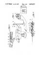
- FIG. 1is a pictorial view showing the present invention in use
- FIG. 2is a pictorial view of the advancer assembly of the present invention
- FIG. 3is a cross-sectional view showing the cutting head of the pesent invention in use removing a lesion from within a vessel;
- FIGS. 4 and 5are pictorial views of the advancer assembly of the present invention.
- FIG. 6is a pictorial view showing the parts of the advancer assembly
- FIG. 7Ais a side view of a section of the guide wire used with the present invention.
- FIGS. 7B and 7Care exploded views illustrating alternative embodiments of a portion of FIG. 7A.
- FIGS. 8 and 9are schematic views of the circuitry used in the power supply of the preferred embodiment of the invention.
- the system 10meets the needed requirements.
- the system 10uses an electric prime mover 12 whose output is connected to the carriage 14 of an advancer assembly 16 via a flexible drive shaft 18.
- the motor 12is capable of developing 20,000 rpm with the torque needed at that speed to overcome frictional losses and to drive a cutting head 20 which is attached to a drive catheter 22, as shown in FIG. 3.
- the cutting head 20, which extends out of a tubular guide sheath 28, and which is guided by a guide wire 29,is used to cut a lesion 24 within a vessel 26.
- Powering the motor 12is a load sensing power supply 30 which will stop the motor 12 and assembly 16 with dynamic braking if the drive catheter 22 or cutting head 20 binds.
- This combinationimproves the safety of the system 10 by preventing undue stress on the vessel 26. It will rapidly stop the differential cutting head 20 in the event of a failure, such as augering, catheter breakage, or jamming by debris.
- a failuresuch as augering, catheter breakage, or jamming by debris.
- the power supply 30automatically corrects for accelerations and decelerations of the drive catheter 22 by continuously testing the load on the prime mover 12. This prevents the inertia of the system 10 from falsely tripping the torque limit of the power supply when the operator accelerates the drive shaft 18 and the other rotating components and prevents augmenting the differential torque threshold when the operator decelerates the rotating components.
- variable torque trip pointSince the size and length of drive catheters 22 is variable, it is necessary to include a variable torque trip point in the design. This allows the operator to correct for catheter drag, aggravated by bends in the drive catheter 22 needed to access lesions, and for different burr diameters, i.e., cutting head 20 sizes.
- the variable torque trip pointfurther permits the operator to correct for parasitic loads in order to maintain an appropriate safety margin in all possible positions and loads of the drive catheter 22 thereon.
- Catheter dragcan be measured easily by simply reducing the threshold of the torque trip control until the system 10 stops. This is done while the system 10 is running in place, with the differential cutting head 20 retracted into the guide sheath 28. The threshold can then be increased as needed to allow for normal cutting loads. The increment would be different for different sizes and types of burrs. To accommodate different diameter drive assemblies, the rotational velocity of the head must be adjustable. This is accomplished by controlling the power supply 30 using a foot pedal 32.
- the advancer assembly 16allows the operator to move the differential cutting head 20 with respect to the guide sheath 28 smoothly and accurately.
- the advancer assembly 16includes a carriage 14 which supports a catheter engagement coupling 34 and houses a driving wheel 35. To advance the drive catheter 22, the carriage 14 is simply moved by hand along a guide rail 36 to any position within the bounds of the saddle 38, i.e, movement of the carriage 14 along the guide rail 36 is permitted within the bounds of the front and rear walls 40, 42, respectively.
- the catheter engagement coupling 34snaps into the carriage 14, simply by pressing it into its receptacle 44 (See FIG. 5), and it is removed in a similar manner.
- the guide sheath 28slips into a universal alignment block 46 on the front of the saddle 38 and the guide wire 29 clamps into a similar block 48 in the rear of the saddle 38. These receptacles 46, 48 make catheter changes quick and easy.
- the process of loading the catheter assemblyuses a number of features of the advancer 16.
- the carriage 14follows a single, round guide rail 36 which allows the carriage 14 to pivot to load the catheter engagement coupling 34. In order to do so, the carriage 14 is pivoted up, and the catheter engagement coupling 34 is snapped into place.
- the guide sheath 28 and guide wire 29are then locked into position by lowering the carriage 14 to its running position while aligning the proximal end 45 of the sheath 28 with its slip fit receptacle 46. Once the proximal end 45 of the sheath 28 has engaged the receptacle 46, the carriage 14 is advanced along the guide rail 36 to its fully advanced position, i.e., toward the front wall 40.
- the alignment blocks 47, 48are adjustable to accommodate any horizontal misalignment.
- the guide wire 29similarly slips into its receptacle 51 at the rear wall 42 of the saddle 38 and is clamped in place using a screw clamp operated by a knob 49. The system 10 is then ready for use.
- Rotational energyis coupled to the drive catheter 22 by the engagement of the drive wheel 35 in the carriage 14 with a driven wheel 50 within the catheter engagement coupling 34 (See FIGS. 2 and 4-6).
- the wheels 35, 50are preferably made of aluminum and urethane foam, respectively.
- the urethane driven wheel 50compresses in the interface between the wheels 35, 50 and thereby sets the preload between the wheels 35, 50. It also has a high coefficient of friction which reduces slippage.
- the off-axis drivefacilitates the coaxial exit of the guide wire 29 and thereby eases the assembly and disassembly of the catheter elements. With this feature, catheter elements can be telescoped together independent of the drive assembly, and, when ready, the entire assembly can be snapped into the advancer 16.
- the catheter engagement coupling 34which is an integral part of the catheter, houses the support bearings 52, 54, and seals 60, 62.
- a linear seal 62is used to form a seal on the guide wire 29 .
- the linear seal 62runs on a semi-rigid section 78 of the guide wire 29 (See FIG. 7A).
- the semi-rigid section 78is preferably made of stainless steel tubing or wire.
- the seal 60is a rotational seal which isolates the access tube 66 and cavity 68 within an end cap 70.
- the two seals 60, 62work together to allow the lumen between the drive catheter 22 and the guide wire 29 to be accessed under operating conditions, thereby allowing the operator to withdraw or inject fluids at any time during the procedure.
- a rigid drive catheter shaft 64which extends from the catheter engagement coupling 34 into the guide sheath 28 to prevent looping of the flexible drive portion of the catheter 22 when the carriage 14 is withdrawn from the fully advanced position. If the flexible shaft was withdrawn from the sheath and left unsupported between the lumen of the guide sheath and the catheter engagement coupling 34, it would tend to whip and loop. The rigid shaft 64 prevents the flexible portion of the drive catheter 22 from being exposed.
- the guide wire 29 used in current vascular therapyis comprised of a spring coil wound with small diameter wires.
- the resulting coilsare from about 0.016 inches to about 0.045 inches in diameter and can be up to 2 meters long.
- solid tube guide wire bodieshave been introduced by various companies, but only in the smallest size (0.016 inches).
- the solid tube type guide wirescan be used directly with the present system 10, but the coiled variety cannot.
- Carriage movementrequires that the guide wire move in and out of the catheter engagement coupling 34.
- a linear sealmust be maintained between the catheter engagement coupling 34 and the guide wire 29.
- the linear seal 62 within the catheter engagement coupling 34performs this task.
- To seal on the guide wire 29, its exterior surfacemust be smooth and even within the area of movement of the seal 62.
- coiled guide wiresmust have integrated a small semi-rigid section 78, preferably of stainless steel tube or rod, of the same or larger diameter in the area of the advancer 16, as shown in FIGS. 7A-7C.
- the physical characteristics of the guide wire 29are unchanged for the most part, but it will be sealable.
- Both movable and fixed core guide wiresare possible with this type of guide wire 29.
- the fixed core type 91is simpler, in that its core 82 and coil 84 are bonded to the end of the semi-rigid section 78.
- the movable core type 86is more complex in that its core 88 must pass through a tubular semi-rigid section 78.
- the tube that comprises the semi-rigid section 78must not allow fluids to escape from the catheter lumen formed between the core 88 and the tube 78, so a seal is needed between the core wire 88 and the tube lumen 78. This is accomplished by using a close tolerance seal between the tube 78 and the core wire 88.
- Some silicone oil 90helps in maintaining the seal.
- the movable core version 86would, of course, have the coil 92 bonded to the tubing section 78 of the guide wire 29.
- the semi-rigid section 78can be made as long or positioned as required to advance the distal tip of the guide wire 29 out of the orifice of the differential cutting head 20 as far as needed. The only requirement is that the semi-rigid section 78 must ride within the lumen of the seal 62 inside the catheter engagement coupling 34 when operating the system 10.
- the lumen access valve 72includes a body 74, an engagement sleeve 76, a thrust washer 81, and an end cap with a clamping fixture 83. It is attached to the distal end of the sheath 28 where it provides a method of sealing the distal end of the guide sheath 28 and a coupling point for fluid connections.
- the valve 72uses an expanding gasket seal 80. When the valve 72 is open, the seal element 80 is removed from contact with the rigid portion 64 of the drive shaft 22 to protect the seal element 80 from the abrasion of the high speed spinning shaft 64. When closed, the valve 72 forms a positive seal allowing materials to be moved with high vacuum or pressure.
- the seal 80is not a rotating seal, hence, the shaft 64 cannot be turning when the seal 80 is engaged.
- the seal 80 used in the preferred embodimentis made of soft latex rubber which can be expanded with little effort. This allows the operator to expand the seal 80 by compressing it directly, rather than by using a threaded element. By combining the operations of closing the valve 72 and locking the source tubes (not shown) into the valve 72, the operator can never attempt to inject fluids with the valve 72 open resulting in loss of the injected material at the proximal end.
- the elements in the sterile field of the systemare the guide wire 29, the guide sheath 28, the advancer assembly 16 and the flexible drive shaft 18 from the prime mover 12. These elements can be made of hemo-compatible materials, such as plastic, silicone, and stainless steel. Elements of the system that do not contact the blood, such as the motor drive shaft 18 and drive wheels 35, 50, can be made of steel and aluminum. In all cases the sterile elements of this system 10 have low dimensional tolerance requirements and can be fabricated very inexpensively with low cost being important to disposibility. Cleaning such a system for reuse is very difficult, because of all the areas within it that can entrap fluid with limited access for cleaning. Having disposable elements is an important advantage and it reduces much of the preparation needed to use the system 10.
- the power supply 100which will produce direct current voltages from about 0 through 120 volts. It also has a DC supply to drive the control circuits.
- the second electronic elementis the control circuitry 200, FIG. 9, whichs include current (or load) sensing, triggering, and dynamic braking elements. Both of these elements are housed in controller 30.
- the variable output power supply 100is a high current source capable of up to 2 amps. To allow for this high current with a large voltage variation a stepped supply was needed to limit control element dissipation. This supply uses 3 steps: 0-40 volts, 40-80 volts, and 80-120 volts. In this way, the dissipation in control transistors T11 and T12 will not exceed 80 watts (40 watts each), but the supply 100 is controllable over a 240 watt range.
- the transistors T9-T12work as a power gain stage from the control output leg of regulator P3. Regulator P3 operates by establishing a nominal 1.25 V reference voltage between the output and the control leg. This reference voltage is impressed across program resistor R43.
- variable resistor R45Since the voltage is constant a constant current flows through resistor R42. This current drains through variable resistor R45 which can then vary the voltage across it by changing its resistance and, thus, control the output voltage.
- the variable resistor R45is placed in the foot pedal 32 along with the voltage switches S1-S3. The switches S1-S3 are synchronized with the variable resistor R45 such that a smooth and continuous transition takes place through the voltage range.
- the current sensing portion of the control circuit 200(See FIG. 9) is comprised of: resistor R5, the biasing network R9-R16 and diodes D4-D9, and operational amplifier P1-1.
- the voltage across R5, which represents the current through it,is biased down and then amplified to be used in the comparator circuit.
- the comparator and latch, P1-2examines the output from the current sense and bias point set with resistor R47 augmented by the supply voltage and its derivative.
- a scaled derivativeis produced by resistors R19-R22, capacitors C1-C4 and C14, and transistors T5 and T6.
- the supply voltageaugments the trip points divider network R24-R26 through series connected R23 and R28.
- the latch, P1-2If the latch, P1-2, is tripped, it is inverted by P1-3 and the signal is used to turn off the transistor switch, T3, removing the power source from the motor 12. The signal is further prepared and delayed by P1-4 to fire the SCR SR1 and short the input lines of the motor 12 to stop it.
- the present inventionmakes use of dynamic torque measurement to test for augering of the burr 20 in atherosclerotic plaque; jamming of the drive catheter 22, caused by breakage or debris, or other malfunctions that would transfer unwanted torque to the vessel itself.
- the torque sensing equipmentis corrected to account for accelerations of the drive system, thereby improving both the safety of the device and its ease of use.
- the safetyis improved, because the torque trip threshold is held apart from the torque due to mechanical energy storage and friction by predetermined amount. In so doing, the angular momentum of the drive system is prevented from interfering with the delivered torque trip threshold.
- the system 10is easy to use, because it will not trip out when the operator tries to rapidly accelerate the drive system.
- Dynamic brakingis used to stop the system 10 in the event of an overload with as little energy transfer to the vessel 26 as possible.
- the drive catheter 22is brought to rest by the prime mover 12 rather than by frictional and load losses.
- the torque trip pointmay be set by an easily accessible control. Since the tortuous path required to access lesions is variable, the frictional drag of the drive catheter 22 is equally variable, and, in many cases, it can exceed the maximum torque required by the burr 20 for cutting. This requires that the frictional load be measured with each catheter size and position. This can be done easily by running the system with the burr 20 withdrawn into the distal end of the guide sheath 28 and adjusting the torque trip control down until the rotating elements of the system 10 stop. Then, the torque trip point is advanced appropriately for the situation.
- an off-axis drivewhich is parallel to the drive catheter 22, for coupling rotational energy to the drive catheter 22 by the engagement of two wheels 35, 50 or gears (not shown).
- This methodallows a guide wire 29 to exit coaxially from the drive catheter 22 while having the prime mover 12 located remotely. It also permits the guide wire 29 to be manipulated independently of the drive catheter 22.
- the off-axis drivealso permits easy separation of driven catheters from driving elements, so that catheter changes can be done quickly and easily. The operator can, therefore, assemble the guide wire 29, the drive catheter 22, and the guide sheath 28 combination without having to thread the elements through an axial port of a prime mover.
- the driven portion of the system 10, in the sterile fieldcan be constructed of inexpensive, disposable components.
- the floating clamps on the holders 48, 47 for the guide wire 29 and guide sheath 28, respectively,remove undue friction by eliminating misalignment problems.
- the holders 47, 48 for the guide sheath 28 and the guide wire 29are located on the distal and proximal ends of the advancer to allow movement in the plane perpendicular to the drive catheter 22. Movement in the direction of the drive catheter 22 is restricted to allow the carriage 14 to control all advancement of the differential cutting head 20.
- Locking the guide wire 29 to the saddle 38makes it stationary with respect to all movement of the drive catheter 22 and the differential cutting head 20.
- a snap together approachis used to assemble the catheter engagement coupling 34 into the carriage 14.
- the catheter engagement coupling 34is keyed so that it will not rotate once snapped down into the receptacle 44 of the carriage 14.
- the binding forceis sufficient to not allow it to dislodge itself while the system 10 is operating.
- This methodmakes catheter changes quick and easy. Also combining the catheter engagement coupling 34 with a rotary union reduces the amount of assembly needed with each catheter change, reduces the size and weight of the drive assembly, and improves its reliability by only requiring one rotating seal.
- Injection of fluids down the guide sheath 28is made possible by the lumen access valve 72.
- This valve 72when engaged, seals the catheter sheath lumen at the proximal end such that injections at high pressure are possible.
- the valve 72is designed so that the connection of a tube or syringe closes the valve 72. In this way, the operator cannot inject fluids that would otherwise exhaust out the proximal end of the guide sheath 28.
- the retractable seal element 80allows the system 10 to run at any speed with no danger of burning the seal 80. This in turn, allows the use of a very soft seal 80 which can be expanded easily by the operator.
- the use of a continuous, semi-rigid section 78 within a coiled guide wire 29makes it possible to form a linear seal on the guide wire 29.
- the placement of the semi-rigid section 78is variable to accommodate guide wire advancement from the orifice of the differential cutting head 20. Since the semi-rigid section 78 is placed within the guide wire 29 proximal that which enters the body, no loss in performance of the guide wire 29 is experienced.
Landscapes
- Health & Medical Sciences (AREA)
- Surgery (AREA)
- Life Sciences & Earth Sciences (AREA)
- Medical Informatics (AREA)
- Nuclear Medicine, Radiotherapy & Molecular Imaging (AREA)
- Engineering & Computer Science (AREA)
- Biomedical Technology (AREA)
- Heart & Thoracic Surgery (AREA)
- Molecular Biology (AREA)
- Animal Behavior & Ethology (AREA)
- General Health & Medical Sciences (AREA)
- Public Health (AREA)
- Veterinary Medicine (AREA)
- Vascular Medicine (AREA)
- Orthopedic Medicine & Surgery (AREA)
- Media Introduction/Drainage Providing Device (AREA)
Abstract
Description
Claims (14)
Priority Applications (1)
| Application Number | Priority Date | Filing Date | Title |
|---|---|---|---|
| US06/649,101US4679557A (en) | 1984-09-10 | 1984-09-10 | Electrodynamic transluminal angioplasty system |
Applications Claiming Priority (1)
| Application Number | Priority Date | Filing Date | Title |
|---|---|---|---|
| US06/649,101US4679557A (en) | 1984-09-10 | 1984-09-10 | Electrodynamic transluminal angioplasty system |
Publications (1)
| Publication Number | Publication Date |
|---|---|
| US4679557Atrue US4679557A (en) | 1987-07-14 |
Family
ID=24603471
Family Applications (1)
| Application Number | Title | Priority Date | Filing Date |
|---|---|---|---|
| US06/649,101Expired - LifetimeUS4679557A (en) | 1984-09-10 | 1984-09-10 | Electrodynamic transluminal angioplasty system |
Country Status (1)
| Country | Link |
|---|---|
| US (1) | US4679557A (en) |
Cited By (80)
| Publication number | Priority date | Publication date | Assignee | Title |
|---|---|---|---|---|
| US4784636A (en)* | 1987-04-30 | 1988-11-15 | Schneider-Shiley (U.S.A.) Inc. | Balloon atheroectomy catheter |
| US4790812A (en)* | 1985-11-15 | 1988-12-13 | Hawkins Jr Irvin F | Apparatus and method for removing a target object from a body passsageway |
| US4808164A (en)* | 1987-08-24 | 1989-02-28 | Progressive Angioplasty Systems, Inc. | Catheter for balloon angioplasty |
| EP0315290A1 (en)* | 1987-10-23 | 1989-05-10 | SCHNEIDER (USA) INC., a Pfizer Company | Atherectomy catheter |
| US4857046A (en)* | 1987-10-21 | 1989-08-15 | Cordis Corporation | Drive catheter having helical pump drive shaft |
| US4927413A (en)* | 1987-08-24 | 1990-05-22 | Progressive Angioplasty Systems, Inc. | Catheter for balloon angioplasty |
| US4942788A (en)* | 1987-11-23 | 1990-07-24 | Interventional Technologies, Inc. | Method of manufacturing a cutter for atherectomy device |
| US4950277A (en)* | 1989-01-23 | 1990-08-21 | Interventional Technologies, Inc. | Atherectomy cutting device with eccentric wire and method |
| EP0387980A1 (en)* | 1989-03-13 | 1990-09-19 | Samuel Shiber | Atherectomy system with a clutch |
| US4966604A (en)* | 1989-01-23 | 1990-10-30 | Interventional Technologies Inc. | Expandable atherectomy cutter with flexibly bowed blades |
| US4986807A (en)* | 1989-01-23 | 1991-01-22 | Interventional Technologies, Inc. | Atherectomy cutter with radially projecting blade |
| US5003918A (en)* | 1989-12-28 | 1991-04-02 | Interventional Technologies, Inc. | Apparatus for manufacturing atherectomy torque tubes |
| US5019089A (en)* | 1989-12-07 | 1991-05-28 | Interventional Technologies Inc. | Atherectomy advancing probe and method of use |
| US5019088A (en)* | 1989-11-07 | 1991-05-28 | Interventional Technologies Inc. | Ovoid atherectomy cutter |
| EP0442137A1 (en)* | 1990-02-14 | 1991-08-21 | Angiomed GmbH & Co. Medizintechnik KG | Atherectomy device |
| US5047040A (en)* | 1987-11-05 | 1991-09-10 | Devices For Vascular Intervention, Inc. | Atherectomy device and method |
| US5062648A (en)* | 1989-09-26 | 1991-11-05 | Interventional Technologies, Inc. | Seal for rotating torque tube with seal valve |
| US5085662A (en)* | 1989-11-13 | 1992-02-04 | Scimed Life Systems, Inc. | Atherectomy catheter and related components |
| AU625943B2 (en)* | 1990-03-21 | 1992-07-16 | Interventional Technologies Inc. | Seal for rotating torque tube with seal valve |
| US5192291A (en)* | 1992-01-13 | 1993-03-09 | Interventional Technologies, Inc. | Rotationally expandable atherectomy cutter assembly |
| US5201750A (en)* | 1989-09-06 | 1993-04-13 | Vascomed Institut Fur Kathetertechnologie Gmbh | Dilation catheter with motor drive for dilation of blood vessels |
| US5207697A (en)* | 1991-06-27 | 1993-05-04 | Stryker Corporation | Battery powered surgical handpiece |
| US5224949A (en)* | 1992-01-13 | 1993-07-06 | Interventional Technologies, Inc. | Camming device |
| US5224945A (en)* | 1992-01-13 | 1993-07-06 | Interventional Technologies, Inc. | Compressible/expandable atherectomy cutter |
| US5287858A (en)* | 1992-09-23 | 1994-02-22 | Pilot Cardiovascular Systems, Inc. | Rotational atherectomy guidewire |
| US5312427A (en)* | 1992-10-16 | 1994-05-17 | Shturman Cardiology Systems, Inc. | Device and method for directional rotational atherectomy |
| US5314438A (en)* | 1992-12-17 | 1994-05-24 | Shturman Cardiology Systems, Inc. | Abrasive drive shaft device for rotational atherectomy |
| US5344395A (en)* | 1989-11-13 | 1994-09-06 | Scimed Life Systems, Inc. | Apparatus for intravascular cavitation or delivery of low frequency mechanical energy |
| US5356418A (en)* | 1992-10-28 | 1994-10-18 | Shturman Cardiology Systems, Inc. | Apparatus and method for rotational atherectomy |
| US5372602A (en)* | 1992-11-30 | 1994-12-13 | Device For Vascular Intervention, Inc. | Method of removing plaque using catheter cutter with torque control |
| US5490859A (en)* | 1992-11-13 | 1996-02-13 | Scimed Life Systems, Inc. | Expandable intravascular occlusion material removal devices and methods of use |
| US5501694A (en)* | 1992-11-13 | 1996-03-26 | Scimed Life Systems, Inc. | Expandable intravascular occlusion material removal devices and methods of use |
| US5540707A (en)* | 1992-11-13 | 1996-07-30 | Scimed Life Systems, Inc. | Expandable intravascular occlusion material removal devices and methods of use |
| FR2739293A1 (en)* | 1995-11-15 | 1997-04-04 | Nogitek Sa | Suction device for removal of fatty tissue |
| US5667490A (en)* | 1992-10-07 | 1997-09-16 | Scimed Life Systems, Inc. | Ablation device drive assembly including catheter connector |
| US5681336A (en)* | 1995-09-07 | 1997-10-28 | Boston Scientific Corporation | Therapeutic device for treating vien graft lesions |
| US5766190A (en)* | 1995-05-24 | 1998-06-16 | Boston Scientific Corporation Northwest Technology Center, Inc. | Connectable driveshaft system |
| US5792157A (en)* | 1992-11-13 | 1998-08-11 | Scimed Life Systems, Inc. | Expandable intravascular occlusion material removal devices and methods of use |
| US5836868A (en)* | 1992-11-13 | 1998-11-17 | Scimed Life Systems, Inc. | Expandable intravascular occlusion material removal devices and methods of use |
| US5897567A (en)* | 1993-04-29 | 1999-04-27 | Scimed Life Systems, Inc. | Expandable intravascular occlusion material removal devices and methods of use |
| WO1999021492A1 (en)* | 1997-10-27 | 1999-05-06 | Shturman Cardiology Systems, Inc. | Rotational atherectomy device with radially expandable prime mover coupling |
| WO1999029240A1 (en) | 1997-12-10 | 1999-06-17 | Shturman Cardiology Systems, Inc. | Rotational atherectomy device with exchangeable drive shaft cartridge |
| US6015420A (en)* | 1997-03-06 | 2000-01-18 | Scimed Life Systems, Inc. | Atherectomy device for reducing damage to vessels and/or in-vivo stents |
| US6024749A (en)* | 1997-10-27 | 2000-02-15 | Shturman Cardiology Systems, Inc. | Rotational atherectomy device with improved exchangeable drive shaft cartridge |
| USRE36764E (en)* | 1991-07-15 | 2000-07-04 | Nadim M. Zacca | Expandable tip atherectomy method and apparatus |
| US6149663A (en)* | 1999-08-17 | 2000-11-21 | Scimed Life Systems, Inc. | Guide wire brake for ablation assembly |
| WO2000056230A3 (en)* | 1999-03-19 | 2001-01-25 | Scimed Life Systems Inc | Atherectomy power control system |
| US6183487B1 (en) | 1997-03-06 | 2001-02-06 | Scimed Life Systems, Inc. | Ablation device for reducing damage to vessels and/or in-vivo stents |
| US6398755B1 (en)* | 1998-10-06 | 2002-06-04 | Scimed Life Systems, Inc. | Driveable catheter system |
| US6503227B1 (en) | 2000-07-24 | 2003-01-07 | Scimed Life Systems, Inc. | Guide wire brake |
| US6514261B1 (en) | 1998-09-30 | 2003-02-04 | Impra, Inc. | Delivery mechanism for implantable stent |
| US20030187468A1 (en)* | 1999-02-02 | 2003-10-02 | Samuel Shiber | Vessel cleaning system with asymmetrical auto retracting agitator |
| US20030216760A1 (en)* | 2002-05-20 | 2003-11-20 | Eric Welch | Apparatus and system for removing an obstruction from a lumen |
| US20040006358A1 (en)* | 2000-04-05 | 2004-01-08 | Pathway Medical Technologies, Inc. | Intralumenal material removal using a cutting device for differential cutting |
| US6818001B2 (en) | 2000-04-05 | 2004-11-16 | Pathway Medical Technologies, Inc. | Intralumenal material removal systems and methods |
| US20050283185A1 (en)* | 2001-07-02 | 2005-12-22 | Linder Richard J | Methods, systems, and devices for providing embolic protection |
| US20080045892A1 (en)* | 2001-05-06 | 2008-02-21 | Ferry Steven J | System and Methods for Advancing a Catheter |
| EP2145593A1 (en)* | 2008-07-17 | 2010-01-20 | Tyco Healthcare Group LP | Piston seal for single incision surgery |
| US8052712B2 (en) | 2001-07-02 | 2011-11-08 | Rubicon Medical, Inc. | Methods, systems, and devices for deploying a filter from a filter device |
| WO2014145548A3 (en)* | 2013-03-15 | 2014-12-31 | Concert Medical, Llc | Method and system for controlling delivery of a fluid to and from a patient |
| US20150313677A1 (en)* | 2009-05-25 | 2015-11-05 | Stereotaxis, Inc. | Remote manipulator device |
| JP2016073684A (en)* | 2010-02-26 | 2016-05-12 | カーディオバスキュラー システムズ, インコーポレイテッド | Rotational atherectomy device with electric motor |
| WO2020210238A1 (en)* | 2019-04-08 | 2020-10-15 | Boston Scientific Scimed, Inc. | Atherectomy system with excess torque protection |
| US10869689B2 (en) | 2017-05-03 | 2020-12-22 | Medtronic Vascular, Inc. | Tissue-removing catheter |
| US10987108B2 (en) | 2013-12-17 | 2021-04-27 | Standard Bariatrics, Inc. | Resection line guide for a medical procedure and method of using same |
| US11173060B2 (en) | 2019-11-04 | 2021-11-16 | Standard Bariatrics, Inc. | Systems and methods of performing surgery using Laplace's law tension retraction during surgery |
| US11197672B2 (en) | 2017-08-14 | 2021-12-14 | Standard Bariatrics, Inc. | Buttress systems and methods for surgical stapling devices and end effectors |
| US11324620B2 (en) | 2015-09-16 | 2022-05-10 | Standard Bariatrics, Inc. | Systems and methods for measuring volume of potential sleeve in a sleeve gastrectomy |
| US11357534B2 (en) | 2018-11-16 | 2022-06-14 | Medtronic Vascular, Inc. | Catheter |
| CN114681016A (en)* | 2020-12-31 | 2022-07-01 | 先健科技(深圳)有限公司 | Volume reduction catheter test system and test method |
| US11452574B1 (en) | 2021-03-23 | 2022-09-27 | Standard Bariatrics, Inc. | Systems and methods for preventing tissue migration in surgical staplers |
| US20220304719A1 (en)* | 2021-03-24 | 2022-09-29 | Medtronic Vascular, Inc. | Tissue-removing catheter with torque control |
| US11510672B2 (en) | 2014-03-29 | 2022-11-29 | Standard Bariatrics, Inc. | End effectors, surgical stapling devices, and methods of using same |
| US11690645B2 (en) | 2017-05-03 | 2023-07-04 | Medtronic Vascular, Inc. | Tissue-removing catheter |
| US11812962B2 (en) | 2014-03-29 | 2023-11-14 | Standard Bariatrics, Inc. | End effectors, surgical stapling devices, and methods of using same |
| US11819236B2 (en) | 2019-05-17 | 2023-11-21 | Medtronic Vascular, Inc. | Tissue-removing catheter |
| WO2023224667A1 (en)* | 2022-05-19 | 2023-11-23 | Cardiovascular Systems, Inc. | Management of stored angular momentum in stalled intravascular rotational drive shafts for atherectomy |
| US12064142B2 (en) | 2020-06-30 | 2024-08-20 | Standard Bariatrics, Inc. | Systems, devices, and methods for preventing or reducing loss of insufflation during a laparoscopic surgical procedure |
| US12171457B2 (en) | 2020-10-30 | 2024-12-24 | Boston Scientific Scimed, Inc. | Atherectomy burrs with blood flow enhancements |
| US12274635B2 (en) | 2019-11-04 | 2025-04-15 | Standard Bariatrics, Inc. | Systems and methods of performing surgery using laplace's law tension retraction during surgery |
Citations (1)
| Publication number | Priority date | Publication date | Assignee | Title |
|---|---|---|---|---|
| US4445509A (en)* | 1982-02-04 | 1984-05-01 | Auth David C | Method and apparatus for removal of enclosed abnormal deposits |
- 1984
- 1984-09-10USUS06/649,101patent/US4679557A/ennot_activeExpired - Lifetime
Patent Citations (1)
| Publication number | Priority date | Publication date | Assignee | Title |
|---|---|---|---|---|
| US4445509A (en)* | 1982-02-04 | 1984-05-01 | Auth David C | Method and apparatus for removal of enclosed abnormal deposits |
Cited By (133)
| Publication number | Priority date | Publication date | Assignee | Title |
|---|---|---|---|---|
| US4790812A (en)* | 1985-11-15 | 1988-12-13 | Hawkins Jr Irvin F | Apparatus and method for removing a target object from a body passsageway |
| US4784636A (en)* | 1987-04-30 | 1988-11-15 | Schneider-Shiley (U.S.A.) Inc. | Balloon atheroectomy catheter |
| US4808164A (en)* | 1987-08-24 | 1989-02-28 | Progressive Angioplasty Systems, Inc. | Catheter for balloon angioplasty |
| US4927413A (en)* | 1987-08-24 | 1990-05-22 | Progressive Angioplasty Systems, Inc. | Catheter for balloon angioplasty |
| US4857046A (en)* | 1987-10-21 | 1989-08-15 | Cordis Corporation | Drive catheter having helical pump drive shaft |
| EP0315290A1 (en)* | 1987-10-23 | 1989-05-10 | SCHNEIDER (USA) INC., a Pfizer Company | Atherectomy catheter |
| US5047040A (en)* | 1987-11-05 | 1991-09-10 | Devices For Vascular Intervention, Inc. | Atherectomy device and method |
| US4942788A (en)* | 1987-11-23 | 1990-07-24 | Interventional Technologies, Inc. | Method of manufacturing a cutter for atherectomy device |
| US4966604A (en)* | 1989-01-23 | 1990-10-30 | Interventional Technologies Inc. | Expandable atherectomy cutter with flexibly bowed blades |
| US4986807A (en)* | 1989-01-23 | 1991-01-22 | Interventional Technologies, Inc. | Atherectomy cutter with radially projecting blade |
| US4950277A (en)* | 1989-01-23 | 1990-08-21 | Interventional Technologies, Inc. | Atherectomy cutting device with eccentric wire and method |
| EP0387980A1 (en)* | 1989-03-13 | 1990-09-19 | Samuel Shiber | Atherectomy system with a clutch |
| US5201750A (en)* | 1989-09-06 | 1993-04-13 | Vascomed Institut Fur Kathetertechnologie Gmbh | Dilation catheter with motor drive for dilation of blood vessels |
| US5062648A (en)* | 1989-09-26 | 1991-11-05 | Interventional Technologies, Inc. | Seal for rotating torque tube with seal valve |
| US5019088A (en)* | 1989-11-07 | 1991-05-28 | Interventional Technologies Inc. | Ovoid atherectomy cutter |
| US5423838A (en)* | 1989-11-13 | 1995-06-13 | Scimed Life Systems, Inc. | Atherectomy catheter and related components |
| US5085662A (en)* | 1989-11-13 | 1992-02-04 | Scimed Life Systems, Inc. | Atherectomy catheter and related components |
| US5344395A (en)* | 1989-11-13 | 1994-09-06 | Scimed Life Systems, Inc. | Apparatus for intravascular cavitation or delivery of low frequency mechanical energy |
| US5019089A (en)* | 1989-12-07 | 1991-05-28 | Interventional Technologies Inc. | Atherectomy advancing probe and method of use |
| US5003918A (en)* | 1989-12-28 | 1991-04-02 | Interventional Technologies, Inc. | Apparatus for manufacturing atherectomy torque tubes |
| EP0442137A1 (en)* | 1990-02-14 | 1991-08-21 | Angiomed GmbH & Co. Medizintechnik KG | Atherectomy device |
| AU625943B2 (en)* | 1990-03-21 | 1992-07-16 | Interventional Technologies Inc. | Seal for rotating torque tube with seal valve |
| US5207697A (en)* | 1991-06-27 | 1993-05-04 | Stryker Corporation | Battery powered surgical handpiece |
| USRE36764E (en)* | 1991-07-15 | 2000-07-04 | Nadim M. Zacca | Expandable tip atherectomy method and apparatus |
| US5224949A (en)* | 1992-01-13 | 1993-07-06 | Interventional Technologies, Inc. | Camming device |
| US5224945A (en)* | 1992-01-13 | 1993-07-06 | Interventional Technologies, Inc. | Compressible/expandable atherectomy cutter |
| US5192291A (en)* | 1992-01-13 | 1993-03-09 | Interventional Technologies, Inc. | Rotationally expandable atherectomy cutter assembly |
| US5287858A (en)* | 1992-09-23 | 1994-02-22 | Pilot Cardiovascular Systems, Inc. | Rotational atherectomy guidewire |
| US5415170A (en)* | 1992-09-23 | 1995-05-16 | Pilot Cardiovascular Systems, Inc. | Rotational atherectomy guidewire |
| US6080171A (en)* | 1992-10-07 | 2000-06-27 | Scimed Life Systems, Inc. | Ablation devices and methods of use |
| US5667490A (en)* | 1992-10-07 | 1997-09-16 | Scimed Life Systems, Inc. | Ablation device drive assembly including catheter connector |
| US5938670A (en)* | 1992-10-07 | 1999-08-17 | Scimed Life Systems, Inc. | Ablation devices and methods of use |
| US5916227A (en)* | 1992-10-07 | 1999-06-29 | Scimed Life Systems, Inc. | Ablation devices and methods of use |
| US5360432A (en)* | 1992-10-16 | 1994-11-01 | Shturman Cardiology Systems, Inc. | Abrasive drive shaft device for directional rotational atherectomy |
| US5312427A (en)* | 1992-10-16 | 1994-05-17 | Shturman Cardiology Systems, Inc. | Device and method for directional rotational atherectomy |
| US5356418A (en)* | 1992-10-28 | 1994-10-18 | Shturman Cardiology Systems, Inc. | Apparatus and method for rotational atherectomy |
| US5490859A (en)* | 1992-11-13 | 1996-02-13 | Scimed Life Systems, Inc. | Expandable intravascular occlusion material removal devices and methods of use |
| US5540707A (en)* | 1992-11-13 | 1996-07-30 | Scimed Life Systems, Inc. | Expandable intravascular occlusion material removal devices and methods of use |
| US5792157A (en)* | 1992-11-13 | 1998-08-11 | Scimed Life Systems, Inc. | Expandable intravascular occlusion material removal devices and methods of use |
| US5836868A (en)* | 1992-11-13 | 1998-11-17 | Scimed Life Systems, Inc. | Expandable intravascular occlusion material removal devices and methods of use |
| US5501694A (en)* | 1992-11-13 | 1996-03-26 | Scimed Life Systems, Inc. | Expandable intravascular occlusion material removal devices and methods of use |
| US5485042A (en)* | 1992-11-30 | 1996-01-16 | Devices For Vascular Intervention, Inc. | Motor drive unit with torque control circuit |
| US5372602A (en)* | 1992-11-30 | 1994-12-13 | Device For Vascular Intervention, Inc. | Method of removing plaque using catheter cutter with torque control |
| US5314438A (en)* | 1992-12-17 | 1994-05-24 | Shturman Cardiology Systems, Inc. | Abrasive drive shaft device for rotational atherectomy |
| US5897567A (en)* | 1993-04-29 | 1999-04-27 | Scimed Life Systems, Inc. | Expandable intravascular occlusion material removal devices and methods of use |
| US5766190A (en)* | 1995-05-24 | 1998-06-16 | Boston Scientific Corporation Northwest Technology Center, Inc. | Connectable driveshaft system |
| US5681336A (en)* | 1995-09-07 | 1997-10-28 | Boston Scientific Corporation | Therapeutic device for treating vien graft lesions |
| FR2739293A1 (en)* | 1995-11-15 | 1997-04-04 | Nogitek Sa | Suction device for removal of fatty tissue |
| US6129734A (en)* | 1997-01-21 | 2000-10-10 | Shturman Cardiology Systems, Inc. | Rotational atherectomy device with radially expandable prime mover coupling |
| US6015420A (en)* | 1997-03-06 | 2000-01-18 | Scimed Life Systems, Inc. | Atherectomy device for reducing damage to vessels and/or in-vivo stents |
| US6482216B1 (en) | 1997-03-06 | 2002-11-19 | Scimed Life Systems, Inc. | Ablation device including guidewire with abrasive tip |
| US6156048A (en)* | 1997-03-06 | 2000-12-05 | Scimed Life Systems, Inc. | Atherectomy device for reducing damage to vessels and/or in-vivo stents |
| US6183487B1 (en) | 1997-03-06 | 2001-02-06 | Scimed Life Systems, Inc. | Ablation device for reducing damage to vessels and/or in-vivo stents |
| US6258109B1 (en) | 1997-03-06 | 2001-07-10 | Scimed Life Systems, Inc. | Guidewire bearing to prevent darting |
| US6270509B1 (en) | 1997-03-06 | 2001-08-07 | Scimed Life Systems, Inc. | Cancave atherectomy burr with smooth rims |
| US6328750B1 (en) | 1997-03-06 | 2001-12-11 | Scimed Life Systems, Inc. | Trifilar atherectomy driveshaft |
| WO1999021492A1 (en)* | 1997-10-27 | 1999-05-06 | Shturman Cardiology Systems, Inc. | Rotational atherectomy device with radially expandable prime mover coupling |
| US6024749A (en)* | 1997-10-27 | 2000-02-15 | Shturman Cardiology Systems, Inc. | Rotational atherectomy device with improved exchangeable drive shaft cartridge |
| US6077282A (en)* | 1997-10-27 | 2000-06-20 | Shturman Cardiology Systems, Inc. | Rotational atherectomy device with exchangeable drive shaft cartridge |
| AU742157B2 (en)* | 1997-10-27 | 2001-12-20 | Cardiovascular Systems, Inc. | Rotational atherectomy device with radially expandable prime mover coupling |
| WO1999029240A1 (en) | 1997-12-10 | 1999-06-17 | Shturman Cardiology Systems, Inc. | Rotational atherectomy device with exchangeable drive shaft cartridge |
| EP1037560A4 (en)* | 1997-12-10 | 2007-06-06 | Cardivascular Systems | Rotational atherectomy device with exchangeable drive shaft cartridge |
| US8852266B2 (en) | 1998-09-30 | 2014-10-07 | Bard Peripheral Vascular, Inc. | Delivery mechanism for implantable stent |
| US6514261B1 (en) | 1998-09-30 | 2003-02-04 | Impra, Inc. | Delivery mechanism for implantable stent |
| US7122050B2 (en) | 1998-09-30 | 2006-10-17 | Bard Peripheral Vascular, Inc. | Delivery mechanism for implantable stent |
| US6398755B1 (en)* | 1998-10-06 | 2002-06-04 | Scimed Life Systems, Inc. | Driveable catheter system |
| US7686816B2 (en)* | 1998-10-06 | 2010-03-30 | Boston Scientific Scimed, Inc. | Driveable catheter systems and methods |
| US6974465B2 (en) | 1998-10-06 | 2005-12-13 | Boston Scientific Scimed, Inc. | Driveable catheter system |
| US20060084911A1 (en)* | 1998-10-06 | 2006-04-20 | Boston Scientific Scimed, Inc. | Driveable catheter systems and methods |
| US20030187468A1 (en)* | 1999-02-02 | 2003-10-02 | Samuel Shiber | Vessel cleaning system with asymmetrical auto retracting agitator |
| US7316697B2 (en) | 1999-02-02 | 2008-01-08 | Samuel Shiber | Vessel cleaning system with asymmetrical auto retracting agitator |
| WO2000056230A3 (en)* | 1999-03-19 | 2001-01-25 | Scimed Life Systems Inc | Atherectomy power control system |
| US6149663A (en)* | 1999-08-17 | 2000-11-21 | Scimed Life Systems, Inc. | Guide wire brake for ablation assembly |
| US6818001B2 (en) | 2000-04-05 | 2004-11-16 | Pathway Medical Technologies, Inc. | Intralumenal material removal systems and methods |
| US20040006358A1 (en)* | 2000-04-05 | 2004-01-08 | Pathway Medical Technologies, Inc. | Intralumenal material removal using a cutting device for differential cutting |
| US7344546B2 (en) | 2000-04-05 | 2008-03-18 | Pathway Medical Technologies | Intralumenal material removal using a cutting device for differential cutting |
| US6503227B1 (en) | 2000-07-24 | 2003-01-07 | Scimed Life Systems, Inc. | Guide wire brake |
| US7766856B2 (en)* | 2001-05-06 | 2010-08-03 | Stereotaxis, Inc. | System and methods for advancing a catheter |
| US20080045892A1 (en)* | 2001-05-06 | 2008-02-21 | Ferry Steven J | System and Methods for Advancing a Catheter |
| US20050283185A1 (en)* | 2001-07-02 | 2005-12-22 | Linder Richard J | Methods, systems, and devices for providing embolic protection |
| US8052712B2 (en) | 2001-07-02 | 2011-11-08 | Rubicon Medical, Inc. | Methods, systems, and devices for deploying a filter from a filter device |
| US7179269B2 (en) | 2002-05-20 | 2007-02-20 | Scimed Life Systems, Inc. | Apparatus and system for removing an obstruction from a lumen |
| US20030216760A1 (en)* | 2002-05-20 | 2003-11-20 | Eric Welch | Apparatus and system for removing an obstruction from a lumen |
| US20080228208A1 (en)* | 2003-03-10 | 2008-09-18 | Pathway Medical Technologies, Inc. | Intralumenal material removal using a cutting device for differential cutting |
| EP2145593A1 (en)* | 2008-07-17 | 2010-01-20 | Tyco Healthcare Group LP | Piston seal for single incision surgery |
| US20100016800A1 (en)* | 2008-07-17 | 2010-01-21 | Brian Rockrohr | Piston seal for single incision surgery |
| US7998118B2 (en) | 2008-07-17 | 2011-08-16 | Tyco Healthcare Group Lp | Piston seal for single incision surgery |
| US20150313677A1 (en)* | 2009-05-25 | 2015-11-05 | Stereotaxis, Inc. | Remote manipulator device |
| JP2016073684A (en)* | 2010-02-26 | 2016-05-12 | カーディオバスキュラー システムズ, インコーポレイテッド | Rotational atherectomy device with electric motor |
| US10420882B2 (en)* | 2013-03-15 | 2019-09-24 | Medovate Limited | Method and system for controllably administering fluid to a patient and/or for controllably withdrawing fluid from the patient |
| CN105451790A (en)* | 2013-03-15 | 2016-03-30 | 协同医学公司 | Method and system for controlling delivery of a fluid to and from a patient |
| WO2014145548A3 (en)* | 2013-03-15 | 2014-12-31 | Concert Medical, Llc | Method and system for controlling delivery of a fluid to and from a patient |
| EP2968737A4 (en)* | 2013-03-15 | 2016-11-09 | Concert Medical Llc | METHOD AND SYSTEM FOR ADMINISTERING FLUID TO PATIENT AND / OR REMOVING FLUID FROM PATIENT IN A CONTROLLABLE MANNER |
| US20160030663A1 (en)* | 2013-03-15 | 2016-02-04 | Concert Medical, Llc | Method and system for controllably administering fluid to a patient and/or for controllably withdrawing fluid from the patient |
| US11712515B2 (en) | 2013-03-15 | 2023-08-01 | Medovate Limited | Method and system for controllably administering fluid to a patient and/or for controllably withdrawing fluid from the patient |
| US11911044B2 (en) | 2013-12-17 | 2024-02-27 | Standard Bariatrics, Inc. | Resection line guide for a medical procedure and method of using same |
| US10987108B2 (en) | 2013-12-17 | 2021-04-27 | Standard Bariatrics, Inc. | Resection line guide for a medical procedure and method of using same |
| US11717295B2 (en) | 2014-03-29 | 2023-08-08 | Standard Bariatrics, Inc. | End effectors, surgical stapling devices, and methods of using same |
| US11510672B2 (en) | 2014-03-29 | 2022-11-29 | Standard Bariatrics, Inc. | End effectors, surgical stapling devices, and methods of using same |
| US11812962B2 (en) | 2014-03-29 | 2023-11-14 | Standard Bariatrics, Inc. | End effectors, surgical stapling devices, and methods of using same |
| US11633184B2 (en) | 2014-03-29 | 2023-04-25 | Standard Bariatrics, Inc. | End effectors, surgical stapling devices, and methods of using same |
| US11324620B2 (en) | 2015-09-16 | 2022-05-10 | Standard Bariatrics, Inc. | Systems and methods for measuring volume of potential sleeve in a sleeve gastrectomy |
| US12329668B2 (en) | 2015-09-16 | 2025-06-17 | Standard Bariatrics, Inc. | Systems and methods for measuring volume of potential sleeve in a sleeve gastrectomy |
| US12114887B2 (en) | 2017-05-03 | 2024-10-15 | Medtronic Vascular, Inc. | Tissue-removing catheter with guidewire isolation liner |
| US10869689B2 (en) | 2017-05-03 | 2020-12-22 | Medtronic Vascular, Inc. | Tissue-removing catheter |
| US10925632B2 (en) | 2017-05-03 | 2021-02-23 | Medtronic Vascular, Inc. | Tissue-removing catheter |
| US11986207B2 (en) | 2017-05-03 | 2024-05-21 | Medtronic Vascular, Inc. | Tissue-removing catheter with guidewire isolation liner |
| US10987126B2 (en) | 2017-05-03 | 2021-04-27 | Medtronic Vascular, Inc. | Tissue-removing catheter with guidewire isolation liner |
| US11896260B2 (en) | 2017-05-03 | 2024-02-13 | Medtronic Vascular, Inc. | Tissue-removing catheter |
| US11051842B2 (en) | 2017-05-03 | 2021-07-06 | Medtronic Vascular, Inc. | Tissue-removing catheter with guidewire isolation liner |
| US11690645B2 (en) | 2017-05-03 | 2023-07-04 | Medtronic Vascular, Inc. | Tissue-removing catheter |
| US11871958B2 (en) | 2017-05-03 | 2024-01-16 | Medtronic Vascular, Inc. | Tissue-removing catheter with guidewire isolation liner |
| US11197672B2 (en) | 2017-08-14 | 2021-12-14 | Standard Bariatrics, Inc. | Buttress systems and methods for surgical stapling devices and end effectors |
| US11559305B2 (en) | 2017-08-14 | 2023-01-24 | Standard Bariatrics, Inc. | Stapling systems and methods for surgical devices and end effectors |
| US11871927B2 (en) | 2017-08-14 | 2024-01-16 | Standard Bariatrics, Inc. | End effectors, surgical stapling devices, and methods of using same |
| US11357534B2 (en) | 2018-11-16 | 2022-06-14 | Medtronic Vascular, Inc. | Catheter |
| US12161359B2 (en) | 2018-11-16 | 2024-12-10 | Medtronic Vascular, Inc. | Catheter |
| WO2020210238A1 (en)* | 2019-04-08 | 2020-10-15 | Boston Scientific Scimed, Inc. | Atherectomy system with excess torque protection |
| CN113784676A (en)* | 2019-04-08 | 2021-12-10 | 波士顿科学国际有限公司 | Atherectomy system with excess torque protection |
| JP7721448B2 (en) | 2019-04-08 | 2025-08-12 | ボストン サイエンティフィック サイムド,インコーポレイテッド | Atherectomy System with Overtorque Protection |
| JP2022526619A (en)* | 2019-04-08 | 2022-05-25 | ボストン サイエンティフィック サイムド,インコーポレイテッド | Atherosclerosis system with excessive torque protection |
| US11819236B2 (en) | 2019-05-17 | 2023-11-21 | Medtronic Vascular, Inc. | Tissue-removing catheter |
| US11602449B2 (en) | 2019-11-04 | 2023-03-14 | Standard Bariatrics, Inc. | Systems and methods of performing surgery using Laplace's law tension retraction during surgery |
| US11173060B2 (en) | 2019-11-04 | 2021-11-16 | Standard Bariatrics, Inc. | Systems and methods of performing surgery using Laplace's law tension retraction during surgery |
| US12274635B2 (en) | 2019-11-04 | 2025-04-15 | Standard Bariatrics, Inc. | Systems and methods of performing surgery using laplace's law tension retraction during surgery |
| US12064142B2 (en) | 2020-06-30 | 2024-08-20 | Standard Bariatrics, Inc. | Systems, devices, and methods for preventing or reducing loss of insufflation during a laparoscopic surgical procedure |
| US12171457B2 (en) | 2020-10-30 | 2024-12-24 | Boston Scientific Scimed, Inc. | Atherectomy burrs with blood flow enhancements |
| CN114681016A (en)* | 2020-12-31 | 2022-07-01 | 先健科技(深圳)有限公司 | Volume reduction catheter test system and test method |
| US12295793B2 (en) | 2021-03-23 | 2025-05-13 | Standard Bariatrics, Inc. | Systems and methods for preventing tissue migration in surgical staplers |
| US11452574B1 (en) | 2021-03-23 | 2022-09-27 | Standard Bariatrics, Inc. | Systems and methods for preventing tissue migration in surgical staplers |
| US11931063B2 (en)* | 2021-03-24 | 2024-03-19 | Medtronic Vascular, Inc. | Tissue-removing catheter with torque control |
| US20220304719A1 (en)* | 2021-03-24 | 2022-09-29 | Medtronic Vascular, Inc. | Tissue-removing catheter with torque control |
| WO2023224667A1 (en)* | 2022-05-19 | 2023-11-23 | Cardiovascular Systems, Inc. | Management of stored angular momentum in stalled intravascular rotational drive shafts for atherectomy |
Similar Documents
| Publication | Publication Date | Title |
|---|---|---|
| US4679557A (en) | Electrodynamic transluminal angioplasty system | |
| US5002553A (en) | Atherectomy system with a clutch | |
| US5267955A (en) | Atherectomy device | |
| US4923462A (en) | Catheter system having a small diameter rotatable drive member | |
| US4732154A (en) | Rotary catheter system | |
| US4986807A (en) | Atherectomy cutter with radially projecting blade | |
| US5135531A (en) | Guided atherectomy system | |
| US6454779B1 (en) | Rotational atherectomy device | |
| US5334160A (en) | Intravascular catheter with sleeve and method for use thereof | |
| US4038985A (en) | Device for repairing arteries | |
| US5626601A (en) | Vascular sealing apparatus and method | |
| US4591355A (en) | Close clearance seal for rotatable therapeutic catheters | |
| US5250060A (en) | Angioplasty apparatus | |
| EP0621761B1 (en) | Surgical cutting tool | |
| US6824551B2 (en) | Percutaneous mechanical fragmentation catheter system | |
| US6921411B2 (en) | Angioplasty apparatus facilitating rapid exchanges and method | |
| EP1267989B1 (en) | Intralumenal material removal systems and methods | |
| US6565588B1 (en) | Intralumenal material removal using an expandable cutting device | |
| US6440148B1 (en) | Stent unclogging system with stepped spiral | |
| CA2061853A1 (en) | Low restenosis atherectomy system | |
| GB2206795A (en) | Apparatus for dilatation catheterization | |
| CA2028641A1 (en) | Fiber tip atherectomy catheter | |
| JPH0613036B2 (en) | Atheroma removal device | |
| CA2068450A1 (en) | Intravascular device such as introducer sheath or balloon catheter or the like and methods for use | |
| US20060184186A1 (en) | Drilling guidewire for treating chronic total occlusion |
Legal Events
| Date | Code | Title | Description |
|---|---|---|---|
| AS | Assignment | Owner name:ADVANCED TECHNOLOGY LABORATORIES, INC., 13208 NORT Free format text:ASSIGNMENT OF ASSIGNORS INTEREST.;ASSIGNORS:OPIE, ERIC A.;CLEMENT, THOMAS J.;REEL/FRAME:004488/0533 Effective date:19850227 Owner name:LAWRENCEVILLE-PRINCETON ROAD, PRINCETON, NEW JERSE Free format text:ASSIGNMENT OF ASSIGNORS INTEREST.;ASSIGNOR:ADVANCED TECHNOLOGY LABORATORIES, INC, A CORP. OF WASH.;REEL/FRAME:004488/0535 Effective date:19851129 | |
| STCF | Information on status: patent grant | Free format text:PATENTED CASE | |
| AS | Assignment | Owner name:HEART TECHNOLOGY, INC., A CORP. OF DE., WASHINGTON Free format text:ASSIGNMENT OF ASSIGNORS INTEREST.;ASSIGNOR:E.R. SQUIBB & SONS, INC., A DE. CORP.;REEL/FRAME:005080/0908 Effective date:19890405 | |
| FEPP | Fee payment procedure | Free format text:PAT HOLDER CLAIMS SMALL ENTITY STATUS - SMALL BUSINESS (ORIGINAL EVENT CODE: SM02); ENTITY STATUS OF PATENT OWNER: LARGE ENTITY | |
| FEPP | Fee payment procedure | Free format text:PAYOR NUMBER ASSIGNED (ORIGINAL EVENT CODE: ASPN); ENTITY STATUS OF PATENT OWNER: LARGE ENTITY | |
| FPAY | Fee payment | Year of fee payment:4 | |
| FEPP | Fee payment procedure | Free format text:PAYOR NUMBER ASSIGNED (ORIGINAL EVENT CODE: ASPN); ENTITY STATUS OF PATENT OWNER: LARGE ENTITY Free format text:PAYER NUMBER DE-ASSIGNED (ORIGINAL EVENT CODE: RMPN); ENTITY STATUS OF PATENT OWNER: LARGE ENTITY | |
| REMI | Maintenance fee reminder mailed | ||
| FPAY | Fee payment | Year of fee payment:8 | |
| SULP | Surcharge for late payment | ||
| AS | Assignment | Owner name:BOSTON SCIENTIFIC CORPORATION NORTHWEST TECHNOLOGY Free format text:CHANGE OF NAME;ASSIGNOR:HEART TECHNOLOGY, INC.;REEL/FRAME:008650/0985 Effective date:19960305 | |
| FEPP | Fee payment procedure | Free format text:PAT HLDR NO LONGER CLAIMS SMALL ENT STAT AS SMALL BUSINESS (ORIGINAL EVENT CODE: LSM2); ENTITY STATUS OF PATENT OWNER: LARGE ENTITY Free format text:PAYER NUMBER DE-ASSIGNED (ORIGINAL EVENT CODE: RMPN); ENTITY STATUS OF PATENT OWNER: LARGE ENTITY | |
| FPAY | Fee payment | Year of fee payment:12 |