US4678573A - Fluid separation module - Google Patents
Fluid separation moduleDownload PDFInfo
- Publication number
- US4678573A US4678573AUS06/525,363US52536383AUS4678573AUS 4678573 AUS4678573 AUS 4678573AUS 52536383 AUS52536383 AUS 52536383AUS 4678573 AUS4678573 AUS 4678573A
- Authority
- US
- United States
- Prior art keywords
- shell
- tube
- slit tube
- rings
- bundle
- Prior art date
- Legal status (The legal status is an assumption and is not a legal conclusion. Google has not performed a legal analysis and makes no representation as to the accuracy of the status listed.)
- Expired - Fee Related
Links
- 239000012530fluidSubstances0.000titleclaimsabstractdescription22
- 238000000926separation methodMethods0.000titleclaimsabstractdescription7
- 239000000835fiberSubstances0.000claimsabstractdescription15
- 239000012510hollow fiberSubstances0.000claimsabstractdescription13
- 239000012528membraneSubstances0.000claimsabstractdescription10
- 239000002184metalSubstances0.000claimsdescription6
- 239000000203mixtureSubstances0.000abstractdescription7
- 238000000034methodMethods0.000abstractdescription3
- 239000000463materialSubstances0.000description3
- 229910000831SteelInorganic materials0.000description1
- 239000002131composite materialSubstances0.000description1
- 230000006835compressionEffects0.000description1
- 238000007906compressionMethods0.000description1
- 238000000502dialysisMethods0.000description1
- 239000004744fabricSubstances0.000description1
- 239000007789gasSubstances0.000description1
- 238000007689inspectionMethods0.000description1
- 239000004745nonwoven fabricSubstances0.000description1
- 238000005371permeation separationMethods0.000description1
- 238000001223reverse osmosisMethods0.000description1
- 229910001220stainless steelInorganic materials0.000description1
- 239000010935stainless steelSubstances0.000description1
- 239000010959steelSubstances0.000description1
- 239000002759woven fabricSubstances0.000description1
Images
Classifications
- B—PERFORMING OPERATIONS; TRANSPORTING
- B01—PHYSICAL OR CHEMICAL PROCESSES OR APPARATUS IN GENERAL
- B01D—SEPARATION
- B01D63/00—Apparatus in general for separation processes using semi-permeable membranes
- B01D63/02—Hollow fibre modules
- B01D63/024—Hollow fibre modules with a single potted end
- B—PERFORMING OPERATIONS; TRANSPORTING
- B01—PHYSICAL OR CHEMICAL PROCESSES OR APPARATUS IN GENERAL
- B01D—SEPARATION
- B01D53/00—Separation of gases or vapours; Recovering vapours of volatile solvents from gases; Chemical or biological purification of waste gases, e.g. engine exhaust gases, smoke, fumes, flue gases, aerosols
- B01D53/22—Separation of gases or vapours; Recovering vapours of volatile solvents from gases; Chemical or biological purification of waste gases, e.g. engine exhaust gases, smoke, fumes, flue gases, aerosols by diffusion
- B—PERFORMING OPERATIONS; TRANSPORTING
- B23—MACHINE TOOLS; METAL-WORKING NOT OTHERWISE PROVIDED FOR
- B23P—METAL-WORKING NOT OTHERWISE PROVIDED FOR; COMBINED OPERATIONS; UNIVERSAL MACHINE TOOLS
- B23P19/00—Machines for simply fitting together or separating metal parts or objects, or metal and non-metal parts, whether or not involving some deformation; Tools or devices therefor so far as not provided for in other classes
- B23P19/02—Machines for simply fitting together or separating metal parts or objects, or metal and non-metal parts, whether or not involving some deformation; Tools or devices therefor so far as not provided for in other classes for connecting objects by press fit or for detaching same
- B23P19/022—Extracting or inserting relatively long parts
- B—PERFORMING OPERATIONS; TRANSPORTING
- B01—PHYSICAL OR CHEMICAL PROCESSES OR APPARATUS IN GENERAL
- B01D—SEPARATION
- B01D2313/00—Details relating to membrane modules or apparatus
- B01D2313/02—Specific tightening or locking mechanisms
- B—PERFORMING OPERATIONS; TRANSPORTING
- B01—PHYSICAL OR CHEMICAL PROCESSES OR APPARATUS IN GENERAL
- B01D—SEPARATION
- B01D2313/00—Details relating to membrane modules or apparatus
- B01D2313/57—Tools used for removal of membranes
Definitions
- This inventionrelates to methods for assembling fluid separation apparatus.
- U.S. Pat. No. 3,526,001discloses a permeation separation apparatus wherein a bundle of hollow fiber membranes positioned in a shell are enclosed in a porous, flexible sleeve.
- the sleevewhich is preferably in the form of a circular knit fabric, aids in handling the bundle of fibers.
- Tension on the sleeveserves to reduce the cross-sectional area of the fiber bundle to facilitate positioning the bundle in a jacket.
- Strappingsuch as rope or metal bands may be placed around the bundle at spaced intervals to compress the bundle for adjusting fluid flow through the bundle.
- U.S. Pat. No. 4,219,426discloses a dialysis device wherein a bundle of fibers mounted in a shell is compressed at spaced intervals by elastic rings which encircle the bundle. The purpose of such compression is to adjust fluid flow through the bundle.
- U.S. Pat. No. 3,526,275discloses a heat exchanger which utilizes a plurality of tubular elements surrounded by a rigid, perforated sleeve unit which has, as one of its purposes, protection of the tubular elements during shipment and handling of the unit.
- the sleeveis apparently made in rigid form primarily for protection of the tubular elements.
- U.S. Pat. No. 3,339,341discloses fluid separation apparatus wherein hollow fiber membranes are positioned within flexible and porous sleeve members which are apparently made of woven or non-woven fabric.
- the sleeve membersare flexible such that they will deform to allow a plurality of such bundles to conform to the configurations of each other and a shell in which the bundles are placed.
- U.S. Pat. No. 3,612,282discloses a reverse osmosis separator unit having a number of composite membrane tubes positioned in a thin metal cannister which is mounted in a pressure vessel.
- the method of mounting a fluid separation module in a cylindrical shellwherein the module is made up of a bundle of hollow fiber filaments which extend through a polymeric tube sheet, the tube sheet being positioned at one end of the fiber bundle.
- a resilient sheet in the form of a slit tubeis secured to the tube sheet and surrounds the bundle of fibers, the slit tube being held in a tubular configuration by a plurality of manually moveable mounted rings which encircle the slit tube and are positioned at spaced intervals thereon.
- the ringsare moved along the slit tube to one end thereof, as the module is slid into the shell, to free the slit tube from restraint such that it expands into contact with the inner surface of the cylindrical shell.
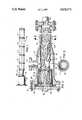
- FIG. 1is a plan view of the module of this invention showing the spaced rings which retain a resilient sheet in a tubular configuration surrounding a bundle of hollow fiber membranes.
- FIG. 2is an enlarged cross-sectional view showing the module in operating position in a shell.
- FIG. 3is a cross-sectional view taken on line 3--3 of FIG. 2 showing the resilient sleeve in an expanded position in contact with the inner surface of the shell.
- a resilient sleeve 11surrounding a plurality of hollow fiber membranes 12 (FIG. 2) which are more permeable to one fluid of the mixture of fluids than other fluids in the mixture.
- the sleeve 11is preferably made from a normally flat, resilient sheet of thin stainless steel which is wrapped around the bundle of fibers 12 to form a slit tube.
- the sleeve of slit tube 11, which is preferably imperforate,is held in this tubular configuration by a plurality of rings 15 which encircle the sleeve 11 and are spaced at intervals therealong as best shown in FIG. 1.
- the resilience of the sleeve 11is such that, if the rings 15 are removed, the sleeve will expand to a substantially larger diameter.
- the rings 15are slideably mounted on the sleeve 11 so that they can be readily pushed to one end of the sleeve or slit tube 11 to allow the sleeve to expand in this manner.
- the term “resilient”we mean that the material from which the sleeve 11 is made has, when in the form of a thin sheet, the capability to substantially recover its original shape or form after being deformed from such original shape or form and then released. With such a resiliency the sleeve will of its own expand from the slit tube configuration essentially back to its original flat sheet configuration, provided that the yield point of the material of the sheet is not exceeded when the original flat sheet is rolled into a tubular configuration.
- One end of the bundle of fibers 12extends through a polymeric tube sheet 16 (FIG. 2) in a known manner.
- the hollow fibersare sealed at the other end of the bundle.
- a metal ring 17 secured to the tube sheet 16 by bolts 18is welded to a tubular distribution element 21 which extends into the end of the slit tube 11.
- a hose clamp of a known type surrounding the slit tube 11 where it overlaps the distribution element 21serves to secure the slit tube to the distribution element 21.
- a metal tube 22 welded to the ring 17surrounds the tube sheet 16 for protecting the tube sheet during handling of the module.
- the module 10is, when the module is in operative position, mounted in a cylindrical steel shell 25 having an enlarged end portion 26 which is provided with an inlet opening 27 for the admission of a mixture of fluids, preferably a mixture of gases, from which one fluid is to be separated by permeation through the hollow fiber membranes to the bores thereof.
- the distribution element 21is provided with ports 28 which allow the fluid mixture to flow into the fiber bundle from the inlet 27.
- the other end of the shell 25is provided with an outlet opening 29 for discharge of the unpermeated fluids.
- the permeated fluidpasses along the bores of the fibers through the tube sheet 16 and exits from the apparatus through an opening 30 in a cover plate 31 which is bolted to the end portion 26 of the shell.
- the permeated fluidcannot exit from the fibers through the sealed ends.
- Gaskets 32 and a seal 33serve to prevent undesired leakage of the fluids.
- the rings 15can be manually moved to the end of the slit tube 11 as the module 21 is inserted in the shell. However, it is preferable to size the rings 15 in such a manner that the shell itself will move the rings to the positions shown in FIG. 2 as the module is slid into the shell.
- the rings 15,which are preferably made of metal or a polymeric material, and have a rectangular cross-sectional configuration, have an inside diameter which is smaller than the inside diameter of the cylindrical shell 25 such that the slit tube 11 is held in a tubular configuration having a diameter less than the inner diameter of the shell 25.
- the outer diameters of the rings 15are greater than the inner diameter of the cylindrical shell 25, such that the end of the cylindrical shell 25, where it is attached to the enlarged end portion 26, will engage the rings 15 and slide these rings along the module 10 as the module is inserted in the shell.
- the ringswill, when the module is fully inserted into the shell, be in the positions shown in FIG. 2, with at least one of the rings being in contact with both the slit tube 11 and the inner surface of the shell in order to provide a seal for preventing the flow of fluids between the slit tube 11 and the shell 25.
- the moduleIn assembling the module 10 in the shell 25 the module is inserted into the shell through the enlarged end portion 26, the cover plate 31 being removed at this time.
- the rings 15may be manually moved down the slit tube 11 as the module is inserted in the shell 25 or the module may be merely slid in the shell, with the end of the cylindrical shell 25 pushing the rings 15 along the slit tube 11 to the positions shown in FIG. 2 when the module is in operative position in the shell.
- Thisfrees the sleeve 11 from confinement and allows it to expand into contact with the inner surface of the shell 25, which in turn allows the fiber bundle to open slightly for an improved flow of the fluid mixture through the bundle.
- the ringsare manually slid along the slit tube 11 to the approximate positions shown in FIG. 1 as the module is withdrawn from the shell. This holds the slit tube 11 in a tubular configuration and prevents it from springing open and spilling the fibers.
Landscapes
- Chemical & Material Sciences (AREA)
- Chemical Kinetics & Catalysis (AREA)
- Engineering & Computer Science (AREA)
- Analytical Chemistry (AREA)
- General Chemical & Material Sciences (AREA)
- Oil, Petroleum & Natural Gas (AREA)
- Mechanical Engineering (AREA)
- Separation Using Semi-Permeable Membranes (AREA)
Abstract
Description
Claims (8)
Priority Applications (1)
| Application Number | Priority Date | Filing Date | Title |
|---|---|---|---|
| US06/525,363US4678573A (en) | 1981-12-21 | 1983-08-22 | Fluid separation module |
Applications Claiming Priority (2)
| Application Number | Priority Date | Filing Date | Title |
|---|---|---|---|
| US33291181A | 1981-12-21 | 1981-12-21 | |
| US06/525,363US4678573A (en) | 1981-12-21 | 1983-08-22 | Fluid separation module |
Related Parent Applications (1)
| Application Number | Title | Priority Date | Filing Date |
|---|---|---|---|
| US33291181AContinuation-In-Part | 1981-12-21 | 1981-12-21 |
Publications (1)
| Publication Number | Publication Date |
|---|---|
| US4678573Atrue US4678573A (en) | 1987-07-07 |
Family
ID=26988459
Family Applications (1)
| Application Number | Title | Priority Date | Filing Date |
|---|---|---|---|
| US06/525,363Expired - Fee RelatedUS4678573A (en) | 1981-12-21 | 1983-08-22 | Fluid separation module |
Country Status (1)
| Country | Link |
|---|---|
| US (1) | US4678573A (en) |
Cited By (8)
| Publication number | Priority date | Publication date | Assignee | Title |
|---|---|---|---|---|
| DE3831786A1 (en)* | 1988-09-19 | 1990-03-29 | Akzo Gmbh | FABRIC AND / OR HEAT EXCHANGER |
| US4975187A (en)* | 1988-11-21 | 1990-12-04 | Lyonnaise Des Eaux | Filter module including a baffle for protecting a bundle of filter fibers |
| US5380433A (en)* | 1993-06-01 | 1995-01-10 | E. I. Du Pont De Nemours And Company | Hollow fiber membrane separation device with a housing made from a flexible material |
| US5604012A (en)* | 1994-01-13 | 1997-02-18 | Teijin Limited | Hollow fiber fabric and process for producing the same |
| US20030178366A1 (en)* | 2000-09-19 | 2003-09-25 | Bo Boye | Device and a method for filtering a fluid |
| US20050184002A1 (en)* | 1995-08-11 | 2005-08-25 | Pedersen Steven K. | Method of potting hollow fiber membranes |
| WO2018077781A1 (en)* | 2016-10-24 | 2018-05-03 | Fresenius Medical Care Deutschland Gmbh | Method for determining a permeation property of hollow fibre membrane bundles |
| US11007486B2 (en)* | 2016-10-24 | 2021-05-18 | Fresenius Medical Care Deutschland Gmbh | Method for determining a permeation property of hollow fibre membranes |
Citations (7)
| Publication number | Priority date | Publication date | Assignee | Title |
|---|---|---|---|---|
| US3339341A (en)* | 1965-12-22 | 1967-09-05 | Du Pont | Fluid separation process and apparatus |
| US3526001A (en)* | 1968-11-26 | 1970-08-25 | Du Pont | Permeation separation device for separating fluids and process relating thereto |
| US3526275A (en)* | 1968-05-27 | 1970-09-01 | Du Pont | Tube bundle assembly having baffle and header seal features for use in plastic tube heat transfer apparatus combinations |
| US3612282A (en)* | 1969-08-14 | 1971-10-12 | Sing Wang Cheng | Supporting structures and containing vessels for reverse osmosis and filtration |
| US4219426A (en)* | 1976-03-19 | 1980-08-26 | Organon Teknika B.V. | Dialysis device |
| US4308654A (en)* | 1979-09-24 | 1982-01-05 | Monsanto Company | Methods for assembling permeators |
| US4380460A (en)* | 1981-12-21 | 1983-04-19 | Monsanto Company | Gas separation apparatus |
- 1983
- 1983-08-22USUS06/525,363patent/US4678573A/ennot_activeExpired - Fee Related
Patent Citations (7)
| Publication number | Priority date | Publication date | Assignee | Title |
|---|---|---|---|---|
| US3339341A (en)* | 1965-12-22 | 1967-09-05 | Du Pont | Fluid separation process and apparatus |
| US3526275A (en)* | 1968-05-27 | 1970-09-01 | Du Pont | Tube bundle assembly having baffle and header seal features for use in plastic tube heat transfer apparatus combinations |
| US3526001A (en)* | 1968-11-26 | 1970-08-25 | Du Pont | Permeation separation device for separating fluids and process relating thereto |
| US3612282A (en)* | 1969-08-14 | 1971-10-12 | Sing Wang Cheng | Supporting structures and containing vessels for reverse osmosis and filtration |
| US4219426A (en)* | 1976-03-19 | 1980-08-26 | Organon Teknika B.V. | Dialysis device |
| US4308654A (en)* | 1979-09-24 | 1982-01-05 | Monsanto Company | Methods for assembling permeators |
| US4380460A (en)* | 1981-12-21 | 1983-04-19 | Monsanto Company | Gas separation apparatus |
Cited By (14)
| Publication number | Priority date | Publication date | Assignee | Title |
|---|---|---|---|---|
| DE3831786A1 (en)* | 1988-09-19 | 1990-03-29 | Akzo Gmbh | FABRIC AND / OR HEAT EXCHANGER |
| US4961464A (en)* | 1988-09-19 | 1990-10-09 | Akzo N.V. | Mass and/or heat exchanger with thermal expansion relief |
| US4975187A (en)* | 1988-11-21 | 1990-12-04 | Lyonnaise Des Eaux | Filter module including a baffle for protecting a bundle of filter fibers |
| US5380433A (en)* | 1993-06-01 | 1995-01-10 | E. I. Du Pont De Nemours And Company | Hollow fiber membrane separation device with a housing made from a flexible material |
| US5604012A (en)* | 1994-01-13 | 1997-02-18 | Teijin Limited | Hollow fiber fabric and process for producing the same |
| US20050184002A1 (en)* | 1995-08-11 | 2005-08-25 | Pedersen Steven K. | Method of potting hollow fiber membranes |
| US20030178366A1 (en)* | 2000-09-19 | 2003-09-25 | Bo Boye | Device and a method for filtering a fluid |
| US7282155B2 (en)* | 2000-09-19 | 2007-10-16 | Fibra Limited | Device and a method for filtering a fluid |
| WO2018077781A1 (en)* | 2016-10-24 | 2018-05-03 | Fresenius Medical Care Deutschland Gmbh | Method for determining a permeation property of hollow fibre membrane bundles |
| CN109890485A (en)* | 2016-10-24 | 2019-06-14 | 费森尤斯医疗护理德国有限责任公司 | Method for determining the permeance property of hollow fiber membrane bundle |
| US11007486B2 (en)* | 2016-10-24 | 2021-05-18 | Fresenius Medical Care Deutschland Gmbh | Method for determining a permeation property of hollow fibre membranes |
| US11052350B2 (en) | 2016-10-24 | 2021-07-06 | Fresenius Medical Care Deutschland Gmbh | Method for determining a permeation property of hollow fibre membrane bundles |
| CN109890485B (en)* | 2016-10-24 | 2021-12-21 | 费森尤斯医疗护理德国有限责任公司 | Method for determining the permeability properties of a bundle of hollow fiber membranes |
| US11541355B2 (en) | 2016-10-24 | 2023-01-03 | Fresenius Medical Care Deutschland Gmbh | Method for determining a permeation property of hollow fibre membrane bundles |
Similar Documents
| Publication | Publication Date | Title |
|---|---|---|
| US4517720A (en) | Method of mounting a fluid separation module in a tubular shell | |
| EP0082835A1 (en) | Gas separation apparatus | |
| US5128037A (en) | Spiral wound filtration membrane cartridge | |
| US4083780A (en) | Fluid purification system | |
| US4548714A (en) | Semipermeable membrane cartridge for use with a pressure container | |
| US5380433A (en) | Hollow fiber membrane separation device with a housing made from a flexible material | |
| US3832830A (en) | Permeation separation device | |
| US4678573A (en) | Fluid separation module | |
| US4666469A (en) | Hollow fiber membrane device with inner wrap | |
| US7758670B2 (en) | Four-port gas separation membrane module assembly | |
| EP1570896A1 (en) | A hollow fiber membrane contactor and method of making same | |
| NZ211144A (en) | Gas filter cartridge:support stays on outer side of filter material pleats | |
| US3953334A (en) | Fluid fractionating apparatus | |
| US4366057A (en) | Oil filter seal membrane | |
| JP3910199B2 (en) | Spiral membrane filter cartridge with chevron seal | |
| JPS6327963B2 (en) | ||
| WO1992000798A1 (en) | Improvements in or relating to flow control | |
| EP0288725A2 (en) | Apparatus and method for protecting gas separation membranes from damage due to a reversal of differential pressure | |
| US5037461A (en) | Filtration apparatus | |
| US4036760A (en) | Fluid fractionating membrane apparatus | |
| EP0443943A1 (en) | Reinforced filtering hose | |
| US5015446A (en) | Catalyst retainer for an elongated tube | |
| JPH06226057A (en) | Hollow fiber membrane type element and hollow fiber membrane module | |
| NO167497B (en) | FLUIDSEPARERINGSMODUL. | |
| JPH0584410A (en) | Reinforced sleeve assembly |
Legal Events
| Date | Code | Title | Description |
|---|---|---|---|
| AS | Assignment | Owner name:MONSANTO COMPANY ST. LOUIS, MO A CORP. OF DE Free format text:ASSIGNMENT OF ASSIGNORS INTEREST.;ASSIGNORS:OTSTOT, ROGER S.;RUNKLE, CHARLES J.;REEL/FRAME:004166/0726 Effective date:19830817 | |
| FEPP | Fee payment procedure | Free format text:PAYOR NUMBER ASSIGNED (ORIGINAL EVENT CODE: ASPN); ENTITY STATUS OF PATENT OWNER: LARGE ENTITY Free format text:PAYER NUMBER DE-ASSIGNED (ORIGINAL EVENT CODE: RMPN); ENTITY STATUS OF PATENT OWNER: LARGE ENTITY | |
| FEPP | Fee payment procedure | Free format text:PAYOR NUMBER ASSIGNED (ORIGINAL EVENT CODE: ASPN); ENTITY STATUS OF PATENT OWNER: LARGE ENTITY | |
| FEPP | Fee payment procedure | Free format text:PAYER NUMBER DE-ASSIGNED (ORIGINAL EVENT CODE: RMPN); ENTITY STATUS OF PATENT OWNER: LARGE ENTITY Free format text:PAYOR NUMBER ASSIGNED (ORIGINAL EVENT CODE: ASPN); ENTITY STATUS OF PATENT OWNER: LARGE ENTITY | |
| FPAY | Fee payment | Year of fee payment:4 | |
| AS | Assignment | Owner name:PERMEA, INC., MISSOURI Free format text:ASSIGNMENT OF ASSIGNORS INTEREST.;ASSIGNOR:MONSANTO COMPANY;REEL/FRAME:005828/0222 Effective date:19910730 | |
| FPAY | Fee payment | Year of fee payment:8 | |
| REMI | Maintenance fee reminder mailed | ||
| LAPS | Lapse for failure to pay maintenance fees | ||
| FP | Lapsed due to failure to pay maintenance fee | Effective date:19990707 | |
| STCH | Information on status: patent discontinuation | Free format text:PATENT EXPIRED DUE TO NONPAYMENT OF MAINTENANCE FEES UNDER 37 CFR 1.362 |