US4678370A - Sewer renovation system - Google Patents
Sewer renovation systemDownload PDFInfo
- Publication number
- US4678370A US4678370AUS06/788,019US78801985AUS4678370AUS 4678370 AUS4678370 AUS 4678370AUS 78801985 AUS78801985 AUS 78801985AUS 4678370 AUS4678370 AUS 4678370A
- Authority
- US
- United States
- Prior art keywords
- liner
- space
- grout
- strip
- sewer
- Prior art date
- Legal status (The legal status is an assumption and is not a legal conclusion. Google has not performed a legal analysis and makes no representation as to the accuracy of the status listed.)
- Expired - Lifetime
Links
Images
Classifications
- E—FIXED CONSTRUCTIONS
- E03—WATER SUPPLY; SEWERAGE
- E03F—SEWERS; CESSPOOLS
- E03F3/00—Sewer pipe-line systems
- E03F3/06—Methods of, or installations for, laying sewer pipes
- F—MECHANICAL ENGINEERING; LIGHTING; HEATING; WEAPONS; BLASTING
- F16—ENGINEERING ELEMENTS AND UNITS; GENERAL MEASURES FOR PRODUCING AND MAINTAINING EFFECTIVE FUNCTIONING OF MACHINES OR INSTALLATIONS; THERMAL INSULATION IN GENERAL
- F16L—PIPES; JOINTS OR FITTINGS FOR PIPES; SUPPORTS FOR PIPES, CABLES OR PROTECTIVE TUBING; MEANS FOR THERMAL INSULATION IN GENERAL
- F16L55/00—Devices or appurtenances for use in, or in connection with, pipes or pipe systems
- F16L55/16—Devices for covering leaks in pipes or hoses, e.g. hose-menders
- F16L55/162—Devices for covering leaks in pipes or hoses, e.g. hose-menders from inside the pipe
- F16L55/165—Devices for covering leaks in pipes or hoses, e.g. hose-menders from inside the pipe a pipe or flexible liner being inserted in the damaged section
- F16L55/1655—Devices for covering leaks in pipes or hoses, e.g. hose-menders from inside the pipe a pipe or flexible liner being inserted in the damaged section a pipe being formed inside the old pipe by winding strip-material
- E—FIXED CONSTRUCTIONS
- E03—WATER SUPPLY; SEWERAGE
- E03F—SEWERS; CESSPOOLS
- E03F3/00—Sewer pipe-line systems
- E03F3/06—Methods of, or installations for, laying sewer pipes
- E03F2003/065—Refurbishing of sewer pipes, e.g. by coating, lining
Definitions
- This inventionrelates to a sewer renovation system.
- Sewerscan become damaged and sometimes blocked due to a number of causes, including earth movement, slime growth, tree root intrusion and pipe erosion due to hydrogen sulphide attacking the material of the sewer pipes.
- the present inventionhas been devised with the general object of providing an efficient but relatively simple and inexpensive method of relining a sewer pipe.
- the inventionresides broadly in a method of lining a sewer pipe including the steps of:
- the lineris pressurised by plugging its ends and introducing fluid thereinto under pressure.
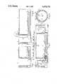
- FIG. 1is a diagrammatic sectional view showing the manner of proving a sewer pipe before renovation commences
- FIG. 2is a diagrammatic sectional view showing the formation and insertion of a liner for the sewer
- FIG. 3is a sectional view, to larger scale, of part of the interlocking strip of which the liner is formed,
- FIG. 4is a diagrammatic sectional and partly brokenaway view of a section of sewer in which the liner has been installed, sealed about its ends and plugged at both ends for pressurizing, and
- FIG. 5is a cross-sectional view along line 5--5 in FIG. 4 to increased scale, and showing the lined sewer pipe after injection of grout.
- the sewer pipe 10 to be renovatedis laid under the ground, indicated at 11, and is accessible at intervals by manholes 12, each normally closed by a cover plate (not shown).
- the seweris normally cleaned by conventional means, and is proved by drawing through it a proving section shown in FIG. 1 at 13. Subsequently a liner 14 is formed and fed through the sewer pipe 10.
- Both the proving section 13 and the liner 14are formed principally of a strip sold under the registered trade mark RIB LOC and shown in section at 15 in FIG. 3, the strip being formed with a number of T-section longitudinal ribs and shaped at its side edges for interlocking engagement of one side edge of a section of the strip with the opposite side edge of an adjacent section of the strip.
- the strip 15can be drawn from a roll 17 and wound to a helix of predetermined diameter, the convolutions of the helix interlocking one with the next as shown in FIG. 3, the form a cylindrical tubular body.
- a solvent cementcan be injected into the interlocking edge portions of the convolutions during the winding process for increased mechanical strength and water-tightness.
- the proving section 13is made at any convenient location by winding a fairly short cylindrical tubular section in this manner and applying to its leading end a nose cone 18.
- the proving sectionis brought into a man hole 12 and is drawn through the sewer pipe 10 by means of a cable 19, which may be passed through the nose cone 18 and tubular section and made fast to a base 20 applied to the trailing end of the section. If the proving section should jam in the pipe 10, it may be removed and a proving section of reduced diameter may be used to determine the required diameter of the liner 14 to be made and installed.
- the winding head 16is installed in a manhole, as shown in FIG. 2, and can be operated to draw the strip 15 from the roll 17 which is located conveniently above ground level.
- a nose cone 21is fitted and secured and the nose cone and formed part of the liner are inserted in the upstream end of the pipe 10.
- the winding head machine 16is then operated to form continuously the liner 14 which is progressively passed through the pipe 10 until it enters a second manhole 12.
- the formed liner 14is then severed so that the winding head 16 may be removed from the manhole.
- FIG. 5a rapid-setting cement fondue 23 (FIG. 4) introduced to the pipe ends 10 about the liner 14 and about the grout inlet pipes.
- the ends of the linerare closed by inflatable plugs 24 and 25.
- Each of these plugsconsists of a resiliently flexible tubular section sealed at its ends about two end discs through the outer one of which water or air may be introduced under pressure to expand the resilient tubular section into firm sealing contact with the interior of the liner.
- Wateris then fed under pressure to the interior of the closed liner by way of a water inlet pipe 26 through the inflatable plug 24 and connected through a valve 27 to any suitable source of water under pressure. Air displaced by the water escapes through an air pipe 28 leading from the upper part of the liner through the plug 24 and by way of a valve 29 to atmosphere, a pressure gauge 30 being connected to the pipe 28. When the liner has been completely filled, water will escape through the air pipe 28, whereupon the valve 29 is closed and, when the water pressure has reached the desired level, for example about 100 kPa, the water valve 27 is closed.
- Groutis then introduced under pressure to the space between the liner 14 and the pipe 10 by way of the grout inlet pipes 22a, 22b, 22c and 22d.
- the groutmay be a constantly agitated mixture of cement, fly ash and water with added plasticizer.
- the groutis fed into the pipe 10 from both ends, by way of a grout feed pipe 31, in or to which are connected a gate valve 32, and overflow pipe 33, a ball valve 34 and a pressure gauge 35.
- Groutis fed from each grout pipe 22 in turn to the two lower grout inlet pipes 22a and 22b, displaced air escaping through the upper grout inlet pipes 22c and 22d.
- the pipes 22a and 22bare then plugged and introduction of grout is continued by way of one of the upper grout inlet pipes 22c and 22d, air escaping from the other.
- the feed of groutis prevented by closing the valves 34 and 32.
- the introduction of groutits pressure can be monitored at the gauges 35. When the predetermined pressure is reached, grout can be quickly bypassed through the pipe 33 by closing the valve 34.
- the grout inlet pipes 22a, 22b, 22c and 22dare of course plugged as soon as their function is completed.
- the plugs 24 and 25are removed and the liner is inspected.
- the length of the RIB LOC stripmay not be sufficient to form the full length of liner between successive manholes, in which case strip from a supplementary roll is added, the two lots of strip 15 being butt-jointed after cutting their ends with a 45° miter and lap-splicing the ends with fast-setting adhesive.
- the lineris wound past the joint and sealed with a rapid setting sealant applied both internally and externally to the joint.
- the sections between manholeswill preferably be lined section by section, tubular liner sections with square-cut ends being winched into position and butt-jointed internally, a joining section being placed in the joint and fixed with solvent cement.
Landscapes
- Engineering & Computer Science (AREA)
- General Engineering & Computer Science (AREA)
- Health & Medical Sciences (AREA)
- Life Sciences & Earth Sciences (AREA)
- Hydrology & Water Resources (AREA)
- Public Health (AREA)
- Water Supply & Treatment (AREA)
- Mechanical Engineering (AREA)
- Lining Or Joining Of Plastics Or The Like (AREA)
- Sewage (AREA)
Abstract
Description
Claims (3)
Applications Claiming Priority (4)
| Application Number | Priority Date | Filing Date | Title |
|---|---|---|---|
| AUPG8408 | 1984-12-04 | ||
| AUPG840884 | 1984-12-04 | ||
| AU42585/85 | 1985-05-16 | ||
| AU42585/85AAU558128B2 (en) | 1984-05-16 | 1985-05-16 | Sewer renovation system |
Publications (1)
| Publication Number | Publication Date |
|---|---|
| US4678370Atrue US4678370A (en) | 1987-07-07 |
Family
ID=25626069
Family Applications (1)
| Application Number | Title | Priority Date | Filing Date |
|---|---|---|---|
| US06/788,019Expired - LifetimeUS4678370A (en) | 1984-12-04 | 1985-10-16 | Sewer renovation system |
Country Status (3)
| Country | Link |
|---|---|
| US (1) | US4678370A (en) |
| EP (1) | EP0184366B1 (en) |
| DE (1) | DE3560841D1 (en) |
Cited By (36)
| Publication number | Priority date | Publication date | Assignee | Title |
|---|---|---|---|---|
| US4767236A (en)* | 1986-06-23 | 1988-08-30 | Nigel Rice | Sewer renovation by expanding a liner within the sewer and placing a new pipe within the expanded liner |
| EP0297385A1 (en)* | 1987-06-30 | 1989-01-04 | Chevron Research And Technology Company | Pipeline rehabilitation method utilizing articulated gasketed joint pipe |
| US4867203A (en)* | 1985-08-23 | 1989-09-19 | Wavin Bv | A method of relining or preparing sewage pipe using a plastic pipe comprising an outer corrugated pipe and a smooth inner wall |
| US4893389A (en)* | 1986-03-25 | 1990-01-16 | Peter Allen | Reinstatement of lateral branch connections in relined sewers or pipes |
| US4954016A (en)* | 1988-04-13 | 1990-09-04 | Oy Wiik & Hoglund Ag | Sewer pipe relining method |
| US4956032A (en)* | 1988-04-28 | 1990-09-11 | Keller Industries Ltd. | Method of grouting using a vacuum |
| US4980116A (en)* | 1989-02-10 | 1990-12-25 | Insituform Of North America, Inc. | Lining of pipelines and passageways |
| US4995929A (en)* | 1986-03-19 | 1991-02-26 | Rib Loc Australia Pty. Ltd. | Method of protecting conduits including helically winding a strip |
| US5002438A (en)* | 1990-01-03 | 1991-03-26 | Strong William A | Method of rehabilitating manholes by custom lining/relining |
| US5063967A (en)* | 1989-12-06 | 1991-11-12 | Stephens Patrick J | Pumpable cement grout |
| US5074943A (en)* | 1987-08-19 | 1991-12-24 | Rib Loc Australia Pty. Ltd. | Slip control for helically wound pipes |
| US5101863A (en)* | 1988-05-02 | 1992-04-07 | Rib Loc Australia Pty. Ltd. | Rehabilitating underground pipes with expanding helically wound liner |
| US5145281A (en)* | 1990-03-29 | 1992-09-08 | Danby Of North America, Inc. | Method of renovating and/or protecting sewers or pipes |
| US5190705A (en)* | 1990-09-14 | 1993-03-02 | Leo Corazza | Method for lining large-diameter pipes |
| US5241993A (en)* | 1989-12-06 | 1993-09-07 | Stephens Patrick J | Method for grouting cavities using a pumpable cement grout |
| US5345971A (en)* | 1990-11-02 | 1994-09-13 | British Gas Plc | Method of replacing branch mains |
| US5386669A (en)* | 1993-03-15 | 1995-02-07 | Almeida; Antonio V. | Corrosion resistant leakproof plastic manhole system |
| WO1996016790A1 (en)* | 1994-12-02 | 1996-06-06 | Sure Grip North America, L.L.C. | A lining system and method for installing a plastic liner |
| US5553971A (en)* | 1988-12-20 | 1996-09-10 | Intelpro Corporation | Double-containment underground piping system |
| WO1998011374A1 (en) | 1996-09-11 | 1998-03-19 | Danby Of North America, Inc. | Material and method for lining pipes |
| US5791378A (en)* | 1993-08-25 | 1998-08-11 | Stephens; Patrick J. | Method for grouting pipe liners |
| US5817200A (en)* | 1994-12-15 | 1998-10-06 | Ameron International Corporation | Surfacing of rehabilitating structures |
| US5865216A (en) | 1995-11-08 | 1999-02-02 | Advanced Polymer Technology, Inc. | System for housing secondarily contained flexible piping |
| US5919002A (en)* | 1997-11-04 | 1999-07-06 | Ramp; Floyd L. | Method of reducing the incursion of storm waters into sanitary sewer systems |
| US5928447A (en)* | 1997-04-03 | 1999-07-27 | Gianfrancisco; Thomas | Conduit repair and interior reconstruction |
| WO2000049322A1 (en)* | 1999-02-17 | 2000-08-24 | Thomas Gianfrancisco | Method and material for repair of conduits and the like |
| USRE37114E1 (en) | 1993-11-01 | 2001-03-27 | Advanced Polymer Technology, Inc. | Secondary containment flexible underground piping system |
| FR2846348A1 (en)* | 2002-10-28 | 2004-04-30 | Marc Gabriel Jean M Dombrowski | Procedure for making sealed channels or chambers in poured, extruded or projected concrete uses plastic film layer coated with adhesive |
| US7137757B1 (en)* | 2005-05-05 | 2006-11-21 | Cosban William C | Method and device for repairing or reinforcing an underground pipe |
| US20080205991A1 (en)* | 2005-04-14 | 2008-08-28 | Ian Roger Bateman | Underground and Partly Submerged Pipe Winding Apparatus and Method |
| US9175798B1 (en)* | 2014-06-05 | 2015-11-03 | Titan CMP Solutions LLC | Trenchless refurbishment of underground pipes |
| JP2016211208A (en)* | 2015-05-07 | 2016-12-15 | 東亜建設工業株式会社 | Manufacturing method of concrete barrier in channel |
| US20170314721A1 (en)* | 2014-10-10 | 2017-11-02 | Ashimori Industry Co., Ltd. | Method for packing filler material |
| US10571065B2 (en) | 2017-03-15 | 2020-02-25 | Fhe Usa Llc | Nondestructive pipe refurbishment using liner pipe sections |
| US20220403970A1 (en)* | 2021-06-01 | 2022-12-22 | Trinity Bay Equipment Holdings, LLC | Bore pressurized pipe handling systems and methods |
| US11892114B2 (en) | 2017-03-15 | 2024-02-06 | Titan CMP Solutions LLC | Expander with accessories to adjust nominal size |
Families Citing this family (12)
| Publication number | Priority date | Publication date | Assignee | Title |
|---|---|---|---|---|
| DE3819657C1 (en)* | 1988-06-09 | 1989-07-20 | Saerbeck-Textil Wagener Kg, 4401 Saerbeck, De | |
| DE3830821A1 (en)* | 1988-09-10 | 1990-03-22 | Niederberg Chemie | Process and apparatus for relining sewer pipes and the like |
| WO1990005873A1 (en)* | 1988-11-21 | 1990-05-31 | Siemens Aktiengesellschaft | Process and device for forming a cylindrical lining in an elongated cavity |
| GB8904227D0 (en)* | 1989-02-24 | 1989-04-12 | Insituform Group Ltd | Improvements relating to the lining of pipelines and passageways(rib-lock modification) |
| JP2511762Y2 (en)* | 1989-12-08 | 1996-09-25 | 積水化学工業株式会社 | Lined existing pipe |
| DE9104682U1 (en)* | 1991-04-17 | 1992-08-20 | Haas, Helmar, 71686 Remseck | Device for sewer rehabilitation |
| DE4139565C2 (en)* | 1991-11-30 | 1995-04-27 | Ecology Engineering Consulting | Liquid-tight lining of sewer pipes |
| DE4213068A1 (en)* | 1992-04-21 | 1993-10-28 | Huels Troisdorf | System and method for relining sewer pipe sections |
| AT400052B (en)* | 1993-05-05 | 1995-09-25 | Klug Kanal Leitungs Und | METHOD FOR LINING A CHANNEL AND INSERTION AND RETURN SLIDE FOR CARRYING OUT THE METHOD ENS |
| AT399184B (en)* | 1993-07-14 | 1995-03-27 | Kuebel Johann | METHOD FOR THE SEALING LINING OF CAVITIES, AND COVERING ELEMENT, IN PARTICULAR FOR IMPLEMENTING THIS METHOD |
| JP2602636B2 (en)* | 1994-12-14 | 1997-04-23 | 積水化学工業株式会社 | Existing pipe lining method |
| GB2302153B (en)* | 1995-06-12 | 1999-10-20 | Wrc Plc | Pipeline renovation |
Citations (16)
| Publication number | Priority date | Publication date | Assignee | Title |
|---|---|---|---|---|
| US2816323A (en)* | 1953-04-22 | 1957-12-17 | Charles G Munger | Method of making plastic lined concrete pipe and joints therein |
| US3123101A (en)* | 1964-03-03 | Method and structure for repairing pipelines | ||
| US3132416A (en)* | 1961-03-14 | 1964-05-12 | Fmc Corp | Method of and apparatus for manufacturing and installing continuous conduit |
| US3422631A (en)* | 1966-11-16 | 1969-01-21 | Daniel Silverman | Method and apparatus for driving and lining an underground conduit |
| US3602263A (en)* | 1968-11-04 | 1971-08-31 | Raymond M Bremner | Pipe relining method and apparatus |
| DE2403044A1 (en)* | 1973-01-22 | 1974-07-25 | Gaz De France | METHOD AND DEVICE FOR REPAIRING OLD PIPELINES |
| DE2317041A1 (en)* | 1973-04-05 | 1974-10-17 | Friedrichsfeld Gmbh | REINFORCED CONCRETE PIPE WITH THERMOPLASTIC INNER SHELL |
| DD115192A1 (en)* | 1974-09-19 | 1975-09-12 | ||
| US3972200A (en)* | 1973-09-20 | 1976-08-03 | Bruno Scarpi | Tunnelling and lining machine |
| DD122129A1 (en)* | 1975-09-29 | 1976-09-12 | ||
| US4209043A (en)* | 1977-10-18 | 1980-06-24 | Rib Loc (Hong Kong) Ltd. | Plastic tubular objects |
| SU785432A1 (en)* | 1977-10-18 | 1980-12-07 | Львовский Ордена Ленина Политехнический Институт | Working member for trencgless laying of pipelines |
| DD146982A5 (en)* | 1977-11-08 | 1981-03-11 | Magyar Tudomanyos Akademia | METHOD FOR INCREASING THE STRENGTH AND WATER-IMPOSSIBLE MATERIALS |
| GB2079805A (en)* | 1980-07-05 | 1982-01-27 | Demco Ltd | Lining underground conduits |
| EP0081983A2 (en)* | 1981-12-14 | 1983-06-22 | Alphacrete Construction Linings (Uk) Limited | Reinforcing member |
| US4566496A (en)* | 1981-10-13 | 1986-01-28 | J-M Manufacturing Company, Inc. | Tubular plastics objects |
- 1985
- 1985-10-16USUS06/788,019patent/US4678370A/ennot_activeExpired - Lifetime
- 1985-11-25DEDE8585308548Tpatent/DE3560841D1/ennot_activeExpired
- 1985-11-25EPEP85308548Apatent/EP0184366B1/ennot_activeExpired
Patent Citations (16)
| Publication number | Priority date | Publication date | Assignee | Title |
|---|---|---|---|---|
| US3123101A (en)* | 1964-03-03 | Method and structure for repairing pipelines | ||
| US2816323A (en)* | 1953-04-22 | 1957-12-17 | Charles G Munger | Method of making plastic lined concrete pipe and joints therein |
| US3132416A (en)* | 1961-03-14 | 1964-05-12 | Fmc Corp | Method of and apparatus for manufacturing and installing continuous conduit |
| US3422631A (en)* | 1966-11-16 | 1969-01-21 | Daniel Silverman | Method and apparatus for driving and lining an underground conduit |
| US3602263A (en)* | 1968-11-04 | 1971-08-31 | Raymond M Bremner | Pipe relining method and apparatus |
| DE2403044A1 (en)* | 1973-01-22 | 1974-07-25 | Gaz De France | METHOD AND DEVICE FOR REPAIRING OLD PIPELINES |
| DE2317041A1 (en)* | 1973-04-05 | 1974-10-17 | Friedrichsfeld Gmbh | REINFORCED CONCRETE PIPE WITH THERMOPLASTIC INNER SHELL |
| US3972200A (en)* | 1973-09-20 | 1976-08-03 | Bruno Scarpi | Tunnelling and lining machine |
| DD115192A1 (en)* | 1974-09-19 | 1975-09-12 | ||
| DD122129A1 (en)* | 1975-09-29 | 1976-09-12 | ||
| US4209043A (en)* | 1977-10-18 | 1980-06-24 | Rib Loc (Hong Kong) Ltd. | Plastic tubular objects |
| SU785432A1 (en)* | 1977-10-18 | 1980-12-07 | Львовский Ордена Ленина Политехнический Институт | Working member for trencgless laying of pipelines |
| DD146982A5 (en)* | 1977-11-08 | 1981-03-11 | Magyar Tudomanyos Akademia | METHOD FOR INCREASING THE STRENGTH AND WATER-IMPOSSIBLE MATERIALS |
| GB2079805A (en)* | 1980-07-05 | 1982-01-27 | Demco Ltd | Lining underground conduits |
| US4566496A (en)* | 1981-10-13 | 1986-01-28 | J-M Manufacturing Company, Inc. | Tubular plastics objects |
| EP0081983A2 (en)* | 1981-12-14 | 1983-06-22 | Alphacrete Construction Linings (Uk) Limited | Reinforcing member |
Non-Patent Citations (11)
| Title |
|---|
| "Sewer Renovation", Second Workshop, Standing Committee on Sewer Systems, (prepared prior to workshop of Sep. 20-23, 1983), pp. 1-8. |
| "Sewer Renovation-Post Conference Papers", Standing Committee on Sewer Systems, Sydney, Australia, Sep. 20-23, 1983 (pp. 67 and 76). |
| Brochure of Hoechst Aktiengesellschaft, "Hoechst Plastics Pipes," pp. 82-87, Apr. 1980. |
| Brochure of Hoechst Aktiengesellschaft, Hoechst Plastics Pipes, pp. 82 87, Apr. 1980.* |
| Sewer Renovation , Second Workshop, Standing Committee on Sewer Systems, (prepared prior to workshop of Sep. 20 23, 1983), pp. 1 8.* |
| Sewer Renovation Post Conference Papers , Standing Committee on Sewer Systems, Sydney, Australia, Sep. 20 23, 1983 (pp. 67 and 76).* |
| Sewerage Rehabilitation Manual, vol. III, Water Research Centre, 1983, pp. III/26 III/28.* |
| Sewerage Rehabilitation Manual, vol. III, Water Research Centre, 1983, pp. III/26-III/28. |
| Spirex Systems, Case History Report No. 83/9, Oct. 1983.* |
| Water Supply and Sewerage, 5th Ed., E. W. Steel and Terence J. McGee, pp. 423 425.* |
| Water Supply and Sewerage, 5th Ed., E. W. Steel and Terence J. McGee, pp. 423-425. |
Cited By (48)
| Publication number | Priority date | Publication date | Assignee | Title |
|---|---|---|---|---|
| US4867203A (en)* | 1985-08-23 | 1989-09-19 | Wavin Bv | A method of relining or preparing sewage pipe using a plastic pipe comprising an outer corrugated pipe and a smooth inner wall |
| US4995929A (en)* | 1986-03-19 | 1991-02-26 | Rib Loc Australia Pty. Ltd. | Method of protecting conduits including helically winding a strip |
| US4893389A (en)* | 1986-03-25 | 1990-01-16 | Peter Allen | Reinstatement of lateral branch connections in relined sewers or pipes |
| US4767236A (en)* | 1986-06-23 | 1988-08-30 | Nigel Rice | Sewer renovation by expanding a liner within the sewer and placing a new pipe within the expanded liner |
| EP0297385A1 (en)* | 1987-06-30 | 1989-01-04 | Chevron Research And Technology Company | Pipeline rehabilitation method utilizing articulated gasketed joint pipe |
| US5074943A (en)* | 1987-08-19 | 1991-12-24 | Rib Loc Australia Pty. Ltd. | Slip control for helically wound pipes |
| US4954016A (en)* | 1988-04-13 | 1990-09-04 | Oy Wiik & Hoglund Ag | Sewer pipe relining method |
| US4956032A (en)* | 1988-04-28 | 1990-09-11 | Keller Industries Ltd. | Method of grouting using a vacuum |
| US5101863A (en)* | 1988-05-02 | 1992-04-07 | Rib Loc Australia Pty. Ltd. | Rehabilitating underground pipes with expanding helically wound liner |
| US5553971A (en)* | 1988-12-20 | 1996-09-10 | Intelpro Corporation | Double-containment underground piping system |
| US6116817A (en)* | 1988-12-20 | 2000-09-12 | Pisces By Opw, Inc. | Hydrocarbon fuel piping system with a flexible inner pipe and an outer pipe |
| US5775842A (en)* | 1988-12-20 | 1998-07-07 | Pisces By Opw, Inc. | Double containment under ground piping system |
| US4980116A (en)* | 1989-02-10 | 1990-12-25 | Insituform Of North America, Inc. | Lining of pipelines and passageways |
| US5427154A (en)* | 1989-12-06 | 1995-06-27 | Stephens; Partick J. | Method for grouting pipe liners |
| US5063967A (en)* | 1989-12-06 | 1991-11-12 | Stephens Patrick J | Pumpable cement grout |
| US5241993A (en)* | 1989-12-06 | 1993-09-07 | Stephens Patrick J | Method for grouting cavities using a pumpable cement grout |
| US5002438A (en)* | 1990-01-03 | 1991-03-26 | Strong William A | Method of rehabilitating manholes by custom lining/relining |
| US5145281A (en)* | 1990-03-29 | 1992-09-08 | Danby Of North America, Inc. | Method of renovating and/or protecting sewers or pipes |
| US5388929A (en)* | 1990-03-29 | 1995-02-14 | Danby Of North America | Method of renovating and/or protecting sewers or pipes |
| US5190705A (en)* | 1990-09-14 | 1993-03-02 | Leo Corazza | Method for lining large-diameter pipes |
| US5433251A (en)* | 1990-11-02 | 1995-07-18 | British Gas Plc | Method of replacing branch mains |
| US5345971A (en)* | 1990-11-02 | 1994-09-13 | British Gas Plc | Method of replacing branch mains |
| US5386669A (en)* | 1993-03-15 | 1995-02-07 | Almeida; Antonio V. | Corrosion resistant leakproof plastic manhole system |
| US5791378A (en)* | 1993-08-25 | 1998-08-11 | Stephens; Patrick J. | Method for grouting pipe liners |
| USRE37114E1 (en) | 1993-11-01 | 2001-03-27 | Advanced Polymer Technology, Inc. | Secondary containment flexible underground piping system |
| WO1996016790A1 (en)* | 1994-12-02 | 1996-06-06 | Sure Grip North America, L.L.C. | A lining system and method for installing a plastic liner |
| US5817200A (en)* | 1994-12-15 | 1998-10-06 | Ameron International Corporation | Surfacing of rehabilitating structures |
| US5865216A (en) | 1995-11-08 | 1999-02-02 | Advanced Polymer Technology, Inc. | System for housing secondarily contained flexible piping |
| US5785456A (en)* | 1996-09-11 | 1998-07-28 | Danby Of North America | Material and method for lining pipes |
| WO1998011374A1 (en) | 1996-09-11 | 1998-03-19 | Danby Of North America, Inc. | Material and method for lining pipes |
| US5928447A (en)* | 1997-04-03 | 1999-07-27 | Gianfrancisco; Thomas | Conduit repair and interior reconstruction |
| US5919002A (en)* | 1997-11-04 | 1999-07-06 | Ramp; Floyd L. | Method of reducing the incursion of storm waters into sanitary sewer systems |
| WO2000049322A1 (en)* | 1999-02-17 | 2000-08-24 | Thomas Gianfrancisco | Method and material for repair of conduits and the like |
| FR2846348A1 (en)* | 2002-10-28 | 2004-04-30 | Marc Gabriel Jean M Dombrowski | Procedure for making sealed channels or chambers in poured, extruded or projected concrete uses plastic film layer coated with adhesive |
| US7476055B2 (en)* | 2005-04-14 | 2009-01-13 | Ian Roger Bateman | Underground and partly submerged pipe winding apparatus and method |
| US20080205991A1 (en)* | 2005-04-14 | 2008-08-28 | Ian Roger Bateman | Underground and Partly Submerged Pipe Winding Apparatus and Method |
| US7241076B1 (en)* | 2005-05-05 | 2007-07-10 | Cosban William C | Method and device for repairing or reinforcing an underground pipe |
| US7137757B1 (en)* | 2005-05-05 | 2006-11-21 | Cosban William C | Method and device for repairing or reinforcing an underground pipe |
| US9175798B1 (en)* | 2014-06-05 | 2015-11-03 | Titan CMP Solutions LLC | Trenchless refurbishment of underground pipes |
| US9322503B2 (en) | 2014-06-05 | 2016-04-26 | Titan CMP Solutions LLC | Nondestructive refurbishment of underground pipes |
| US20170314721A1 (en)* | 2014-10-10 | 2017-11-02 | Ashimori Industry Co., Ltd. | Method for packing filler material |
| US10228087B2 (en)* | 2014-10-10 | 2019-03-12 | Ashimori Industry Co., Ltd. | Method for packing filler material |
| JP2016211208A (en)* | 2015-05-07 | 2016-12-15 | 東亜建設工業株式会社 | Manufacturing method of concrete barrier in channel |
| US10571065B2 (en) | 2017-03-15 | 2020-02-25 | Fhe Usa Llc | Nondestructive pipe refurbishment using liner pipe sections |
| US10746341B2 (en) | 2017-03-15 | 2020-08-18 | Titan CMP Solutions LLC | Pusher box for nondestructive pipe refurbishment in confined spaces |
| US11892114B2 (en) | 2017-03-15 | 2024-02-06 | Titan CMP Solutions LLC | Expander with accessories to adjust nominal size |
| US20220403970A1 (en)* | 2021-06-01 | 2022-12-22 | Trinity Bay Equipment Holdings, LLC | Bore pressurized pipe handling systems and methods |
| US11892112B2 (en)* | 2021-06-01 | 2024-02-06 | Trinity Bay Equipment Holdings, LLC | Bore pressurized pipe handling systems and methods |
Also Published As
| Publication number | Publication date |
|---|---|
| EP0184366A1 (en) | 1986-06-11 |
| EP0184366B1 (en) | 1987-10-28 |
| DE3560841D1 (en) | 1987-12-03 |
Similar Documents
| Publication | Publication Date | Title |
|---|---|---|
| US4678370A (en) | Sewer renovation system | |
| US4954016A (en) | Sewer pipe relining method | |
| GB2041147A (en) | Renovating sewers | |
| US4995761A (en) | Method and apparatus for repairing ruptures in underground conduits | |
| US5049003A (en) | Method and apparatus for repairing ruptures in underground conduits | |
| AU2002328732B2 (en) | Installation assemblies for pipeline liners, pipeline liners and methods for installing the same | |
| US5167258A (en) | Re-lining of sewers | |
| JPS61236994A (en) | Method of sealing joining section or leakage section | |
| US4893389A (en) | Reinstatement of lateral branch connections in relined sewers or pipes | |
| JPS6393991A (en) | Method of repairing existing underground pipe | |
| US20080075538A1 (en) | Method and apparatus for repairing underground pipes | |
| US1949650A (en) | Method of making concrete conduits | |
| JPS6041269B2 (en) | How to repair old pipes | |
| US5785456A (en) | Material and method for lining pipes | |
| EP0078816A1 (en) | Pipe connecting method | |
| EP0101712B1 (en) | A lining hose for restoring or making a conveyor channel | |
| US4889449A (en) | Slipliner grouting method and system | |
| US20250320946A1 (en) | Methods and apparatus for providing access to an underground pipe | |
| US12060963B1 (en) | Method and system for encapsulating in-ground asbestos concrete pipe | |
| JP3889301B2 (en) | Pipe laying device, laying system and laying method | |
| WO2019232566A1 (en) | Expanding packer | |
| JPH01199083A (en) | Old pipe renewing method | |
| Ouellette et al. | Rehabilitation of sanitary sewer pipelines | |
| JPH0814347B2 (en) | Old pipe rehabilitation method | |
| JP2001159476A (en) | Lining construction method for existing pipe passage |
Legal Events
| Date | Code | Title | Description |
|---|---|---|---|
| AS | Assignment | Owner name:DANBY PTY. LTD., 67 RANDOLPH STREET, ROCKLEA, QUEE Free format text:ASSIGNMENT OF ASSIGNORS INTEREST.;ASSIGNOR:ALLEN, PETER;REEL/FRAME:004469/0268 Effective date:19851004 | |
| STCF | Information on status: patent grant | Free format text:PATENTED CASE | |
| FEPP | Fee payment procedure | Free format text:PAYOR NUMBER ASSIGNED (ORIGINAL EVENT CODE: ASPN); ENTITY STATUS OF PATENT OWNER: SMALL ENTITY Free format text:PAT HLDR NO LONGER CLAIMS SMALL ENT STAT AS INDIV INVENTOR (ORIGINAL EVENT CODE: LSM1); ENTITY STATUS OF PATENT OWNER: SMALL ENTITY | |
| AS | Assignment | Owner name:DANBY OF NORTH AMERICA, INC., MARYLAND Free format text:ASSIGNMENT OF ASSIGNORS INTEREST.;ASSIGNOR:DANBY PTY, LTD.;REEL/FRAME:005219/0845 Effective date:19891110 | |
| FPAY | Fee payment | Year of fee payment:4 | |
| FEPP | Fee payment procedure | Free format text:PAT HOLDER CLAIMS SMALL ENTITY STATUS - SMALL BUSINESS (ORIGINAL EVENT CODE: SM02); ENTITY STATUS OF PATENT OWNER: SMALL ENTITY | |
| FEPP | Fee payment procedure | Free format text:PAYER NUMBER DE-ASSIGNED (ORIGINAL EVENT CODE: RMPN); ENTITY STATUS OF PATENT OWNER: SMALL ENTITY | |
| FPAY | Fee payment | Year of fee payment:8 | |
| FPAY | Fee payment | Year of fee payment:12 |