US4676312A - Well casing grip assurance system - Google Patents
Well casing grip assurance systemDownload PDFInfo
- Publication number
- US4676312A US4676312AUS06/937,894US93789486AUS4676312AUS 4676312 AUS4676312 AUS 4676312AUS 93789486 AUS93789486 AUS 93789486AUS 4676312 AUS4676312 AUS 4676312A
- Authority
- US
- United States
- Prior art keywords
- elevator
- spider
- fluid pressure
- valve
- casing
- Prior art date
- Legal status (The legal status is an assumption and is not a legal conclusion. Google has not performed a legal analysis and makes no representation as to the accuracy of the status listed.)
- Expired - Lifetime
Links
- 241000239290AraneaeSpecies0.000claimsabstractdescription77
- 239000012530fluidSubstances0.000claimsabstractdescription59
- 238000009434installationMethods0.000claimsabstract3
- 238000000034methodMethods0.000claimsdescription5
- 238000005553drillingMethods0.000claimsdescription4
- 238000013022ventingMethods0.000claimsdescription4
- 230000003319supportive effectEffects0.000claimsdescription2
- 230000000712assemblyEffects0.000description4
- 238000000429assemblyMethods0.000description4
- 238000010276constructionMethods0.000description1
- 238000012986modificationMethods0.000description1
- 230000004048modificationEffects0.000description1
- 230000035484reaction timeEffects0.000description1
Images

Classifications
- E—FIXED CONSTRUCTIONS
- E21—EARTH OR ROCK DRILLING; MINING
- E21B—EARTH OR ROCK DRILLING; OBTAINING OIL, GAS, WATER, SOLUBLE OR MELTABLE MATERIALS OR A SLURRY OF MINERALS FROM WELLS
- E21B19/00—Handling rods, casings, tubes or the like outside the borehole, e.g. in the derrick; Apparatus for feeding the rods or cables
- E21B19/02—Rod or cable suspensions
- E21B19/06—Elevators, i.e. rod- or tube-gripping devices
- E21B19/07—Slip-type elevators
Definitions
- This inventiongenerally relates to methods and apparatus for installing and removing well bore pipe and more particularly pertains to a fluid operated interlock system for assuring that at least one or both of casing elevator slips and casing spider slips have full and complete grip on a well casing before the other slip can be released from the casing.
- Pneumatic casing toolsare gripping devices used to hold and lower tubular well casing into a pre-drilled hole.
- the toolsare used in sets consisting of one elevator slip assembly and one spider slip assembly.
- the elevator and spider slip assembliesare identical tools except for the accessories used with each tool.
- the first problem associated with the use of these toolsis related to gripping the casing collar which is of a larger diameter than the nominal diameter of the well casing.
- the problemis caused by not lowering the elevator slip assembly far enough below the collar.
- Such slip assembliesare designed such that the gripping forces generated are sufficient for proper gripping only when the slips are lowered sufficiently below a casing collar as to completely grip the nominal diameter of the well casing.
- the slipsare not allowed to go sufficiently deep into the tool body to generate adequate gripping forces. The result is that, when the casing string is lifted with the slips gripping the collar rather than the casing diameter, the drill string will sometimes slip through the slips and drop into well bore below.
- the next problemis caused by improper operation of the gripping tools.
- the person working up in the derrickcalled the "stabber" operates the control valve that closes the elevator slips. Once the elevator slips are closed and the weight of the casing string is on the elevator, the stabber sometimes actuates the control valve to the open direction. However, with the string weight hanging on the elevator, the air pressure alone will not open the slips. The proper time to actuate the control valve is after the string is lowered and the spider assembly slips are closed, and not before.
- the principal object of the present inventionis to assure that one set of slips is closed down on the well casing at all times such that one set of slips may not be released from the well casing until the other set of slips has a firm grip on the will casing.
- Another object of the present inventionis to deactivate the elevator slips and/or the spider slips against inadvertent actuation unless the other set of slips are fully set in gripping position.
- apparatus for installing casing in a well boreincluding a drilling rig having a traveling block and a supportive rig floor, a casing gripping fluid actuated casing elevator assembly carried by the traveling block and a casing gripping fluid actuated casing spider assembly mounted on the rig floor.
- the elevator assembly and the spider assemblyeach has a piston in a pressurable closing chamber to actuate slips into gripping engagement with well casing when the closing chamber is pressurized, and also a pressurable opening chamber also containing a piston to move the slips into release from the casing when the opening chamber is pressurized.
- the improvementis casing grip control apparatus for assuring correct and appropriate gripping of the elevator assembly and the spider assembly onto well casing.
- the apparatusincludes a first two-position control valve respectively connected into the closing chamber and into the opening chamber of the elevator assembly and a second two-position control valve respectively connected into the closing chamber and into the opening chamber of the spider assembly.
- Each of the first and the second control valvesare optionally actuated to admit fluid pressure alternately into a closing chamber and an opening chamber while venting the other chamber to atmosphere.
- a third two-position control valveis connected to be in a first position when the spider is in fully closed gripping position and in a second position when the spider is in position other than fully closed.
- a forth two-way control valveis connected to be in a first position when the elevator is in a fully closed gripping position and in a second position when the elevator is in position other than fully closed.
- the third valveis connected to pass fluid pressure from a pressure source to the first valve only when the third valve is in its first position as caused by the spider being in fully closed gripping position.
- the fourth valveis connected to pass fluid pressure from a pressure source to the second valve only when the fourth valve is in its first position responding to fully closed gripping position of the elevator.
- the improvementalso includes a method of assuring that at least one of the elevator or the spider is fully closed in gripping connection about a well casing before the other may be released from fully closed gripping connection about a well casing with the steps including: (a) passing fluid pressure from a pressure source through a two-position spider position valve to a two-position elevator valve connected to admit fluid pressure into the elevator slips and optionally directing the fluid pressure to open and to close said elevator with the spider position valve being connected to the spider for passing fluid pressure to the elevator valve only when the spider is fully closed into gripping position about well casing and; (b) passing fluid pressure from a pressure source through a two-position elevator position valve to a spider valve which is connected into the spider and optionally directing the fluid pressure to open and close the spider, the elevator position valve being connected to the elevator for passing fluid pressure to the spider valve only when the elevator valve is fully closed into gripping position about well casing.
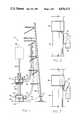
- FIG. 1is a partial elevational view of a drilling rig showing an elevator supported by bales from a traveling block and a spider slip assembly supported by the rig floor;
- FIG. 2illustrates the appropriate and proper setting of slips into a bowl to seat about a well casing
- FIG. 3is an elevational view similar to FIG. 2 but showing the slips incorrectly or improperly seated about the collar of a well casing and not properly seated into the slip bowl;
- FIG. 4is a schematic illustration of the elevator slip assembly and the spider slip assembly along with the fluid pressure connections of the operator actuated valves and the slip position actuated valves of the present invention.
- FIG. 1there is shown the pertinent portion of a drilling rig 10 which is rigged to run well casing with an elevator slip assembly 12 suspended from bales 28 and a traveling block 26 (indicated in dashed lines), and a spider slip assembly 18 supported on the rig floor 24.
- the elevator 12carries a bell guide 14 and a casing guide 16.
- the spider assembly 18carries a bottom guide 20, shown in dashed lines, and a spider top guide 22 as shown.
- the elevator and the spiderare air actuated from an air supply 42 which passes through a conduit or hose 38 to the elevator 12 and through a conduit or hose 40 to the spider 18.
- an air supply 42which passes through a conduit or hose 38 to the elevator 12 and through a conduit or hose 40 to the spider 18.
- conduits or hoses 44 and 46Interconnected between the elevator 12 and the spider 18 are conduits or hoses 44 and 46 which have a purpose made more clear with reference to FIG. 4.
- Air pressureas used herein is sometimes referred to in this specification and claims as fluid pressure and it will be obvious to those skilled in this type of equipment that the equipment is operable with hydraulic fluid which would also be included in the term fluid pressure.
- Airis the preferred media, however, and this description of the preferred embodiment employs air pressure as the actuating media.
- FIG. 2schematically illustrates a slip member 30 seated in a slip bowl 32 and firmly engaged in gripping contact with well casing 34 just below a casing collar 36.
- This FIG. 2illustrates the internal configuration of both the elevator 12 and the spider 18 when the slips 30 are correctly seated.
- FIG. 3schematically illustrates a situation where the slip member 30 has engaged with the casing collar 36, has not been correctly seated in the slip bowl 32, and has not been seated correctly around the casing 34.
- the "cocking" of the slip 30is exaggerated but it can be seen that the gripping action of slip member 30 is pecarious at best and subject to being dislodged with little “bumping" of the casing against some obstruction in the well bore.
- the elevator slip assembly 12 and the slip spider assembly 18are illustrated in FIG. 4 purely for functionality and do not reflect the actual internal construction of the elevator 12 and the spider 18 as appearing in FIG. 1. It will be seen that the schematic representation of elevator 12 and spider 18 is similar to corresponding assemblies as shown in U.S. Pat. No. 3,722,603. Though schematic and functional, the elevator 12 and the spider 18 as shown in FIG. 4 accurately correspond to the function of the same elements or parts thereof as shown in FIGS. 1-3.
- the elevator 12is to include a plurality of slips 30 adapted to be guided into a slip bowl 32 to be engaged and disengaged from the well casing 34.
- the slips 30are pulled up in retracted position so as to be free and clear of the casing 34 and the casing collar 36.
- the elevator 12is equipped with two slip piston cylinder assemblies 48 which form respectively a slip release pressure chamber 50 and a slip closure pressure chamber 52.
- the slip release chambers 50are connected through a conduit 54 into a manually actuated two-position slip actuator valve 58.
- the slip closure chambers 52are connected through a slip closure conduit or line 56 also into the two-position valve 58.
- the valve 58is adapted to admit fluid pressure into slip release chambers 50 while venting fluid pressure from the slip closure chambers 52 through the line 56 to atmosphere. When the valve 58 is shifted to its second position, fluid pressure is admitted to the slip closure chambers 52 while venting pressure from the release chambers 50 through line 54 to atmosphere.
- Fluid pressureis admitted into the control valve 58 through a conduit or line 44 from a slip closure interlock valve 60.
- the interlock valve 60is a two-position valve mechanically connected to the slips 130 and the bowl 132 of the spider assembly 18 as indicated by the dashed lines 70.
- the interlock control valve 60is supplied with fluid pressure through a conduit or line 40 from an air supply source illustrated as a pressure regulator and filter 42.
- the mechanical connection 70is arranged to position valve 60 to pass air from line 40 through valve 60 and line 44 to the valve 58 at such time as the slips 130 are fully seated in the slip bowl 132 into firm gripping engagement with the casing 34. At such time as the slip 130 is in position other than positive engagement with the casing 34, the mechanical linkage 70 has positioned the interlock control valve 60 to block the passage of fluid pressure from the line 40 into the line 44 and thereby to the valve 58.
- valve 58has no air pressure supplied to actuate the elevator 12 in any manner excepting at such time as the slips 130 are fully seated into gripping position about the casing 34.
- the elements and connections of the spider assembly 18are the same as described for elevator 12 such that like elements and conduits or lines bear the same number with a "1" prefix. Accordingly, the spider assembly 18 has slip release chambers 150 connected through a line 154 into a two-position valve 158 and slip closure chambers 152 connected through a line 156 to the valve 158.
- the two-position slip actuator valve 158, the interlock position valve 160is mechanically connected to the slips 30 and the slip bowl 32 of the elevator 12 by mechanical connection 170 indicated by dashed lines as previously described with reference to the mechanical connection 70 for the interlock position valve 60.
- the valve 160is connected through a conduit or line 38 to the fluid supply 42 as previously described.
- the mechanical linkage 170has actuated the interlock position valve 160 to a position preventing fluid pressure from the line 38 to pass through the valve.
- the valve 158is without fluid pressure and fluid pressure cannot be supplied to pressure either the chambers 150 or 152 until the linkage 170 is actuated by seating of the elevator slips 30 within the bowl 32 to firmly grip casing 34 by the elevator assembly 32.
- FIG. 4in view of FIGS. 1 and 2, the spider 18 is set on the rig floor and the elevator 12 is suspended from the traveling block 26 and bales 28 as shown.
- the casing string 34is suspended into the hole from elevator 12 and lowered by the traveling block 26.
- the slips in the spider 18are opened and the pipe 34 travels freely through it.
- the slips of the elevatorare closed and firmly grip casing 34.
- the elevator 12is lowered over the casing to a point below the collar at the top of that last joint.
- the elevator slips 30are then closed and the elevator is used to lift the entire string of casing 34 a very short distance. This short lift is to enable the slips 130 and the spider 18 to be opened. Now the entire casing string 34 is again suspended from the elevator 12, thus allowing the whole string to be lowered to start the sequence again for another single joint of casing.
- the grip assurance interlock system shown in FIG. 4assures that, at all times, one set of the slips 30 or 130 are closed into firm gripping contact with the body of the casing 34. If one set is not closed then the other set will not be able to be energized to be released.
- interlock valves 60 and 160positioning of the interlock valves 60 and 160 by their respective linkages 70 and 170 is critical such that the respective actuating valves 58 and 158 may be actuated only when the other of the respective slips 30 and 130 are closed into firm gripping engagement with the pipe body. Closing either set of slips on a larger diameter such as a collar 36 would not permit the respective position valve 60 or 160 to actuate as described. The system therefore assures that at least one of elevator 12 or spider 18 will be firmly gripping the casing 34 at all times.
- the system described aboveis one that utilized compressed air to open and close the slips as well as a way of transmitting signals from one tool to the other. It is readily seen that the same interlock system herein described could be used in a hydraulic circuit equally well, providing that various components are designed for hydraulic operation. It is also readily apparent that the system as herein described could be an electropnumatic system or an electrohydraulic system with the valves disclosed actuated by electrical solenoids connected through appropriate limits switches.
Landscapes
- Engineering & Computer Science (AREA)
- Life Sciences & Earth Sciences (AREA)
- Geology (AREA)
- Mining & Mineral Resources (AREA)
- Mechanical Engineering (AREA)
- Physics & Mathematics (AREA)
- Environmental & Geological Engineering (AREA)
- Fluid Mechanics (AREA)
- General Life Sciences & Earth Sciences (AREA)
- Geochemistry & Mineralogy (AREA)
- Types And Forms Of Lifts (AREA)
Abstract
Description
Claims (12)
Priority Applications (1)
| Application Number | Priority Date | Filing Date | Title |
|---|---|---|---|
| US06/937,894US4676312A (en) | 1986-12-04 | 1986-12-04 | Well casing grip assurance system |
Applications Claiming Priority (1)
| Application Number | Priority Date | Filing Date | Title |
|---|---|---|---|
| US06/937,894US4676312A (en) | 1986-12-04 | 1986-12-04 | Well casing grip assurance system |
Publications (1)
| Publication Number | Publication Date |
|---|---|
| US4676312Atrue US4676312A (en) | 1987-06-30 |
Family
ID=25470538
Family Applications (1)
| Application Number | Title | Priority Date | Filing Date |
|---|---|---|---|
| US06/937,894Expired - LifetimeUS4676312A (en) | 1986-12-04 | 1986-12-04 | Well casing grip assurance system |
Country Status (1)
| Country | Link |
|---|---|
| US (1) | US4676312A (en) |
Cited By (91)
| Publication number | Priority date | Publication date | Assignee | Title |
|---|---|---|---|---|
| US4793410A (en)* | 1988-06-13 | 1988-12-27 | Bowen Tools, Inc. | Load detection and indicator apparatus for well tubing or the like |
| US4842058A (en)* | 1988-09-26 | 1989-06-27 | Bowen Tools, Inc. | Load detection and indicator apparatus for well tubing or the like |
| EP0589823A1 (en)* | 1992-09-04 | 1994-03-30 | Varco International, Inc. | Safety pipe string elevator |
| US5343962A (en)* | 1992-08-24 | 1994-09-06 | Ingersoll-Rand Company | Double rod cylinder feed system |
| US5595248A (en)* | 1995-08-25 | 1997-01-21 | Den-Con Tool Co. | Pipe alignment apparatus |
| US5653290A (en)* | 1995-05-12 | 1997-08-05 | Campbell Industries Ltd. | Rotating rod string position adjusting device |
| US5765651A (en)* | 1997-04-10 | 1998-06-16 | Sweeney; Gerald T. | Cable-tool casing hammer |
| WO1998031914A1 (en) | 1997-01-17 | 1998-07-23 | Castille Dale J | Apparatus and method for improved tubular grip assurance |
| EP0887510A1 (en)* | 1997-06-25 | 1998-12-30 | Weatherford Oil Tool GmbH | Safety switch system for slip-type elevators |
| GB2357530A (en)* | 2000-11-04 | 2001-06-27 | Weatherford Lamb | Apparatus and method for gripping and releasing tubulars including a grip assurance mechanism |
| WO2002036927A1 (en) | 2000-11-04 | 2002-05-10 | Weatherford/Lamb, Inc. | Combined grip control of elevator and spider slips |
| WO2002092959A1 (en)* | 2001-05-17 | 2002-11-21 | Weatherford/Lamb, Inc. | Apparatus and methods for tubular makeup interlock |
| US20030141111A1 (en)* | 2000-08-01 | 2003-07-31 | Giancarlo Pia | Drilling method |
| US6615931B2 (en) | 2002-01-07 | 2003-09-09 | Boart Longyear Co. | Continuous feed drilling system |
| US6622796B1 (en) | 1998-12-24 | 2003-09-23 | Weatherford/Lamb, Inc. | Apparatus and method for facilitating the connection of tubulars using a top drive |
| US6626238B2 (en) | 2001-12-12 | 2003-09-30 | Offshore Energy Services, Inc. | Remote sensor for determining proper placement of elevator slips |
| US6688398B2 (en) | 1998-08-24 | 2004-02-10 | Weatherford/Lamb, Inc. | Method and apparatus for connecting tubulars using a top drive |
| US6705405B1 (en) | 1998-08-24 | 2004-03-16 | Weatherford/Lamb, Inc. | Apparatus and method for connecting tubulars using a top drive |
| US6725938B1 (en) | 1998-12-24 | 2004-04-27 | Weatherford/Lamb, Inc. | Apparatus and method for facilitating the connection of tubulars using a top drive |
| US20040129456A1 (en)* | 1994-10-14 | 2004-07-08 | Weatherford/Lamb, Inc. | Methods and apparatus for cementing drill strings in place for one pass drilling and completion of oil and gas wells |
| US20040188097A1 (en)* | 2001-10-05 | 2004-09-30 | Van Rijzingen Johannes Wilhelmus Henricus | Non-seize material attachment for a drill slip system |
| US20040251025A1 (en)* | 2003-01-30 | 2004-12-16 | Giroux Richard L. | Single-direction cementing plug |
| US6843463B1 (en)* | 2002-08-30 | 2005-01-18 | Varco I/P/ Inc. | Pressure regulated slip ram on a coil tubing blowout preventer |
| US20050051343A1 (en)* | 1998-07-22 | 2005-03-10 | Weatherford/Lamb, Inc. | Apparatus for facilitating the connection of tubulars using a top drive |
| US20050067168A1 (en)* | 2003-09-29 | 2005-03-31 | Baird Jeffery D. | Method and apparatus for controlling the ascent and descent of pipe in a well bore |
| US6976298B1 (en) | 1998-08-24 | 2005-12-20 | Weatherford/Lamb, Inc. | Methods and apparatus for connecting tubulars using a top drive |
| US20050279507A1 (en)* | 2004-06-07 | 2005-12-22 | Folk Robert A | Tubular clamp apparatus for top drives & methods of use |
| US6994176B2 (en) | 2002-07-29 | 2006-02-07 | Weatherford/Lamb, Inc. | Adjustable rotating guides for spider or elevator |
| US7004264B2 (en) | 2002-03-16 | 2006-02-28 | Weatherford/Lamb, Inc. | Bore lining and drilling |
| US7013997B2 (en) | 1994-10-14 | 2006-03-21 | Weatherford/Lamb, Inc. | Methods and apparatus for cementing drill strings in place for one pass drilling and completion of oil and gas wells |
| US7036610B1 (en) | 1994-10-14 | 2006-05-02 | Weatherford / Lamb, Inc. | Apparatus and method for completing oil and gas wells |
| US7040420B2 (en) | 1994-10-14 | 2006-05-09 | Weatherford/Lamb, Inc. | Methods and apparatus for cementing drill strings in place for one pass drilling and completion of oil and gas wells |
| US7083005B2 (en) | 2002-12-13 | 2006-08-01 | Weatherford/Lamb, Inc. | Apparatus and method of drilling with casing |
| US7090023B2 (en) | 2002-10-11 | 2006-08-15 | Weatherford/Lamb, Inc. | Apparatus and methods for drilling with casing |
| US7096982B2 (en) | 2003-02-27 | 2006-08-29 | Weatherford/Lamb, Inc. | Drill shoe |
| US7100713B2 (en) | 2000-04-28 | 2006-09-05 | Weatherford/Lamb, Inc. | Expandable apparatus for drift and reaming borehole |
| US20060201684A1 (en)* | 2005-03-10 | 2006-09-14 | Throttle Control Tech Inc. | Throttle limiting control box for snubbing units in conjunction with service or drilling rigs |
| US7108084B2 (en) | 1994-10-14 | 2006-09-19 | Weatherford/Lamb, Inc. | Methods and apparatus for cementing drill strings in place for one pass drilling and completion of oil and gas wells |
| US7117957B2 (en) | 1998-12-22 | 2006-10-10 | Weatherford/Lamb, Inc. | Methods for drilling and lining a wellbore |
| US7131505B2 (en) | 2002-12-30 | 2006-11-07 | Weatherford/Lamb, Inc. | Drilling with concentric strings of casing |
| US7140445B2 (en) | 1997-09-02 | 2006-11-28 | Weatherford/Lamb, Inc. | Method and apparatus for drilling with casing |
| US7147068B2 (en) | 1994-10-14 | 2006-12-12 | Weatherford / Lamb, Inc. | Methods and apparatus for cementing drill strings in place for one pass drilling and completion of oil and gas wells |
| US7165634B2 (en) | 1994-10-14 | 2007-01-23 | Weatherford/Lamb, Inc. | Method and apparatus for cementing drill strings in place for one pass drilling and completion of oil and gas wells |
| US7188687B2 (en) | 1998-12-22 | 2007-03-13 | Weatherford/Lamb, Inc. | Downhole filter |
| US7191840B2 (en) | 2003-03-05 | 2007-03-20 | Weatherford/Lamb, Inc. | Casing running and drilling system |
| US7216727B2 (en) | 1999-12-22 | 2007-05-15 | Weatherford/Lamb, Inc. | Drilling bit for drilling while running casing |
| US7228901B2 (en) | 1994-10-14 | 2007-06-12 | Weatherford/Lamb, Inc. | Method and apparatus for cementing drill strings in place for one pass drilling and completion of oil and gas wells |
| US7264067B2 (en) | 2003-10-03 | 2007-09-04 | Weatherford/Lamb, Inc. | Method of drilling and completing multiple wellbores inside a single caisson |
| US7284617B2 (en) | 2004-05-20 | 2007-10-23 | Weatherford/Lamb, Inc. | Casing running head |
| US7303022B2 (en) | 2002-10-11 | 2007-12-04 | Weatherford/Lamb, Inc. | Wired casing |
| US7311148B2 (en) | 1999-02-25 | 2007-12-25 | Weatherford/Lamb, Inc. | Methods and apparatus for wellbore construction and completion |
| US7325610B2 (en) | 2000-04-17 | 2008-02-05 | Weatherford/Lamb, Inc. | Methods and apparatus for handling and drilling with tubulars or casing |
| US7334650B2 (en) | 2000-04-13 | 2008-02-26 | Weatherford/Lamb, Inc. | Apparatus and methods for drilling a wellbore using casing |
| US7360594B2 (en) | 2003-03-05 | 2008-04-22 | Weatherford/Lamb, Inc. | Drilling with casing latch |
| US7370707B2 (en) | 2003-04-04 | 2008-05-13 | Weatherford/Lamb, Inc. | Method and apparatus for handling wellbore tubulars |
| US20080149326A1 (en)* | 2004-07-16 | 2008-06-26 | Frank's Casing Crew & Rental Tools, Inc. | Method and Apparatus for Positioning the Proximal End of a Tubular String Above a Spider |
| US20080174131A1 (en)* | 2007-01-19 | 2008-07-24 | Vernon Joseph Bouligny | Single Joint Elevator Having Deployable Jaws |
| US7413020B2 (en) | 2003-03-05 | 2008-08-19 | Weatherford/Lamb, Inc. | Full bore lined wellbores |
| US20080277108A1 (en)* | 2007-05-09 | 2008-11-13 | Frank's Casing Crew & Rental Tools, Inc. | Single joint elevator with gripping jaws |
| US20090014169A1 (en)* | 2007-07-12 | 2009-01-15 | Frank's Casing Crew & Rental Tools, Inc. | Single joint elevator with jaws secured by a powered door |
| EP2028339A1 (en) | 2005-09-20 | 2009-02-25 | National Oilwell Varco, L.P. | Elevator for handling pipe |
| US7503397B2 (en) | 2004-07-30 | 2009-03-17 | Weatherford/Lamb, Inc. | Apparatus and methods of setting and retrieving casing with drilling latch and bottom hole assembly |
| US7509722B2 (en) | 1997-09-02 | 2009-03-31 | Weatherford/Lamb, Inc. | Positioning and spinning device |
| US20090272542A1 (en)* | 2008-05-03 | 2009-11-05 | Frank's Casing Crew And Rental Tools, Inc. | Tubular Grip Interlock System |
| US7650944B1 (en) | 2003-07-11 | 2010-01-26 | Weatherford/Lamb, Inc. | Vessel for well intervention |
| US7669662B2 (en) | 1998-08-24 | 2010-03-02 | Weatherford/Lamb, Inc. | Casing feeder |
| US7694744B2 (en) | 2005-01-12 | 2010-04-13 | Weatherford/Lamb, Inc. | One-position fill-up and circulating tool and method |
| US7712523B2 (en) | 2000-04-17 | 2010-05-11 | Weatherford/Lamb, Inc. | Top drive casing system |
| US7758746B2 (en) | 2006-10-06 | 2010-07-20 | Vary Petrochem, Llc | Separating compositions and methods of use |
| US7757759B2 (en) | 2006-04-27 | 2010-07-20 | Weatherford/Lamb, Inc. | Torque sub for use with top drive |
| US7845418B2 (en) | 2005-01-18 | 2010-12-07 | Weatherford/Lamb, Inc. | Top drive torque booster |
| US7862709B2 (en) | 2006-10-06 | 2011-01-04 | Vary Petrochem, Llc | Separating compositions and methods of use |
| US7874352B2 (en) | 2003-03-05 | 2011-01-25 | Weatherford/Lamb, Inc. | Apparatus for gripping a tubular on a drilling rig |
| US7882902B2 (en) | 2006-11-17 | 2011-02-08 | Weatherford/Lamb, Inc. | Top drive interlock |
| US20110114308A1 (en)* | 2009-11-16 | 2011-05-19 | Tesco Corporation | Hydraulic Interlock System Between Casing Gripper and Spider |
| WO2011109293A1 (en) | 2010-03-01 | 2011-09-09 | Frank's International , Inc. | Elevator grip assurance |
| USRE42877E1 (en) | 2003-02-07 | 2011-11-01 | Weatherford/Lamb, Inc. | Methods and apparatus for wellbore construction and completion |
| US8062512B2 (en) | 2006-10-06 | 2011-11-22 | Vary Petrochem, Llc | Processes for bitumen separation |
| WO2012091727A1 (en)* | 2010-12-30 | 2012-07-05 | Canrig Drilling Technology Ltd. | Tubular handling device and methods |
| CN102767358A (en)* | 2011-05-05 | 2012-11-07 | 斯纳伯考制造股份有限公司 | System and method for monitoring and controlling snubbing slips |
| CN102877801A (en)* | 2012-09-29 | 2013-01-16 | 济南光先数控机械有限公司 | Hydraulic slip |
| US8356675B2 (en) | 2007-04-27 | 2013-01-22 | Weatherford/Lamb, Inc. | Apparatus and methods for tubular makeup interlock |
| US20130118760A1 (en)* | 2011-11-15 | 2013-05-16 | Canrig Drilling Technology Ltd. | Weight-based interlock apparatus and methods |
| US20130133900A1 (en)* | 2011-11-30 | 2013-05-30 | Herwig Michael Sredensek | Slip Bowl Load Transfer System |
| US8851164B2 (en) | 2008-06-26 | 2014-10-07 | Canrig Drilling Technology Ltd. | Tubular handling device and methods |
| US9303472B2 (en) | 2008-06-26 | 2016-04-05 | Canrig Drilling Technology Ltd. | Tubular handling methods |
| US9404322B2 (en) | 2010-12-17 | 2016-08-02 | Weatherford Technology Holdings, Llc | Electronic control system for a tubular handling tool |
| US9500047B2 (en) | 2013-07-31 | 2016-11-22 | Stingray Offshore Solutions, LLC | Method and apparatus for supporting a tubular |
| US9745804B2 (en) | 2015-03-02 | 2017-08-29 | Full Flow Technologies, Llc | Cylinder assembly for snubbing and drilling applications |
| US10196860B2 (en) | 2014-09-17 | 2019-02-05 | David C. Wright | Telescopic mini-rig |
| US11686179B2 (en) | 2021-11-22 | 2023-06-27 | Saudi Arabian Oil Company | Catching dropped tubulars |
Citations (10)
| Publication number | Priority date | Publication date | Assignee | Title |
|---|---|---|---|---|
| US3096075A (en)* | 1960-12-09 | 1963-07-02 | Brown Oil Tools | Hydraulic pipe snubber for oil wells |
| US3215203A (en)* | 1961-04-17 | 1965-11-02 | Otis Eng Co | Apparatus for moving a well flow conductor into or out of a well |
| US3708020A (en)* | 1971-01-15 | 1973-01-02 | J Adamson | Continuous feed head drill assembly |
| US3722603A (en)* | 1971-09-16 | 1973-03-27 | Brown Oil Tools | Well drilling apparatus |
| US3999610A (en)* | 1974-11-21 | 1976-12-28 | Otis Engineering Corporation | Pipe snubbing method and apparatus |
| US4051988A (en)* | 1975-08-19 | 1977-10-04 | Nitro Nobel Ab | Tube feeding device for use in charging shotholes with explosive through a pipe or tube |
| US4085796A (en)* | 1976-11-16 | 1978-04-25 | Otis Engineering Corporation | Well tubing handling system |
| US4476936A (en)* | 1981-12-21 | 1984-10-16 | Varco International, Inc. | Jacking mechanism supported by a wellhead |
| US4494376A (en)* | 1981-07-20 | 1985-01-22 | Varco International, Inc. | Fluid actuated jack mechanism |
| US4595062A (en)* | 1980-07-17 | 1986-06-17 | Varco International, Inc. | Well casing jack mechanism |
- 1986
- 1986-12-04USUS06/937,894patent/US4676312A/ennot_activeExpired - Lifetime
Patent Citations (10)
| Publication number | Priority date | Publication date | Assignee | Title |
|---|---|---|---|---|
| US3096075A (en)* | 1960-12-09 | 1963-07-02 | Brown Oil Tools | Hydraulic pipe snubber for oil wells |
| US3215203A (en)* | 1961-04-17 | 1965-11-02 | Otis Eng Co | Apparatus for moving a well flow conductor into or out of a well |
| US3708020A (en)* | 1971-01-15 | 1973-01-02 | J Adamson | Continuous feed head drill assembly |
| US3722603A (en)* | 1971-09-16 | 1973-03-27 | Brown Oil Tools | Well drilling apparatus |
| US3999610A (en)* | 1974-11-21 | 1976-12-28 | Otis Engineering Corporation | Pipe snubbing method and apparatus |
| US4051988A (en)* | 1975-08-19 | 1977-10-04 | Nitro Nobel Ab | Tube feeding device for use in charging shotholes with explosive through a pipe or tube |
| US4085796A (en)* | 1976-11-16 | 1978-04-25 | Otis Engineering Corporation | Well tubing handling system |
| US4595062A (en)* | 1980-07-17 | 1986-06-17 | Varco International, Inc. | Well casing jack mechanism |
| US4494376A (en)* | 1981-07-20 | 1985-01-22 | Varco International, Inc. | Fluid actuated jack mechanism |
| US4476936A (en)* | 1981-12-21 | 1984-10-16 | Varco International, Inc. | Jacking mechanism supported by a wellhead |
Cited By (171)
| Publication number | Priority date | Publication date | Assignee | Title |
|---|---|---|---|---|
| US4793410A (en)* | 1988-06-13 | 1988-12-27 | Bowen Tools, Inc. | Load detection and indicator apparatus for well tubing or the like |
| US4842058A (en)* | 1988-09-26 | 1989-06-27 | Bowen Tools, Inc. | Load detection and indicator apparatus for well tubing or the like |
| US5343962A (en)* | 1992-08-24 | 1994-09-06 | Ingersoll-Rand Company | Double rod cylinder feed system |
| EP0589823A1 (en)* | 1992-09-04 | 1994-03-30 | Varco International, Inc. | Safety pipe string elevator |
| US7040420B2 (en) | 1994-10-14 | 2006-05-09 | Weatherford/Lamb, Inc. | Methods and apparatus for cementing drill strings in place for one pass drilling and completion of oil and gas wells |
| US20040129456A1 (en)* | 1994-10-14 | 2004-07-08 | Weatherford/Lamb, Inc. | Methods and apparatus for cementing drill strings in place for one pass drilling and completion of oil and gas wells |
| US7100710B2 (en) | 1994-10-14 | 2006-09-05 | Weatherford/Lamb, Inc. | Methods and apparatus for cementing drill strings in place for one pass drilling and completion of oil and gas wells |
| US7228901B2 (en) | 1994-10-14 | 2007-06-12 | Weatherford/Lamb, Inc. | Method and apparatus for cementing drill strings in place for one pass drilling and completion of oil and gas wells |
| US7013997B2 (en) | 1994-10-14 | 2006-03-21 | Weatherford/Lamb, Inc. | Methods and apparatus for cementing drill strings in place for one pass drilling and completion of oil and gas wells |
| US7165634B2 (en) | 1994-10-14 | 2007-01-23 | Weatherford/Lamb, Inc. | Method and apparatus for cementing drill strings in place for one pass drilling and completion of oil and gas wells |
| US7108084B2 (en) | 1994-10-14 | 2006-09-19 | Weatherford/Lamb, Inc. | Methods and apparatus for cementing drill strings in place for one pass drilling and completion of oil and gas wells |
| US7147068B2 (en) | 1994-10-14 | 2006-12-12 | Weatherford / Lamb, Inc. | Methods and apparatus for cementing drill strings in place for one pass drilling and completion of oil and gas wells |
| US7036610B1 (en) | 1994-10-14 | 2006-05-02 | Weatherford / Lamb, Inc. | Apparatus and method for completing oil and gas wells |
| US5653290A (en)* | 1995-05-12 | 1997-08-05 | Campbell Industries Ltd. | Rotating rod string position adjusting device |
| US5595248A (en)* | 1995-08-25 | 1997-01-21 | Den-Con Tool Co. | Pipe alignment apparatus |
| EP1099824A3 (en)* | 1997-01-17 | 2001-09-05 | Dale J. Castille | An apparatus for optionally gripping and releasing a tube |
| US5791410A (en)* | 1997-01-17 | 1998-08-11 | Frank's Casing Crew & Rental Tools, Inc. | Apparatus and method for improved tubular grip assurance |
| WO1998031914A1 (en) | 1997-01-17 | 1998-07-23 | Castille Dale J | Apparatus and method for improved tubular grip assurance |
| US5765651A (en)* | 1997-04-10 | 1998-06-16 | Sweeney; Gerald T. | Cable-tool casing hammer |
| US6386282B1 (en) | 1997-06-25 | 2002-05-14 | Weatherford/Lamb, Inc. | Safety switching system for clamping devices for pipes |
| WO1999000577A1 (en)* | 1997-06-25 | 1999-01-07 | Weatherford/Lamb, Inc. | Safety switching system for clamping devices for pipes |
| EP0887510A1 (en)* | 1997-06-25 | 1998-12-30 | Weatherford Oil Tool GmbH | Safety switch system for slip-type elevators |
| US7140445B2 (en) | 1997-09-02 | 2006-11-28 | Weatherford/Lamb, Inc. | Method and apparatus for drilling with casing |
| US7509722B2 (en) | 1997-09-02 | 2009-03-31 | Weatherford/Lamb, Inc. | Positioning and spinning device |
| US7137454B2 (en) | 1998-07-22 | 2006-11-21 | Weatherford/Lamb, Inc. | Apparatus for facilitating the connection of tubulars using a top drive |
| US20050051343A1 (en)* | 1998-07-22 | 2005-03-10 | Weatherford/Lamb, Inc. | Apparatus for facilitating the connection of tubulars using a top drive |
| US7665531B2 (en) | 1998-07-22 | 2010-02-23 | Weatherford/Lamb, Inc. | Apparatus for facilitating the connection of tubulars using a top drive |
| US6688398B2 (en) | 1998-08-24 | 2004-02-10 | Weatherford/Lamb, Inc. | Method and apparatus for connecting tubulars using a top drive |
| US7451826B2 (en) | 1998-08-24 | 2008-11-18 | Weatherford/Lamb, Inc. | Apparatus for connecting tubulars using a top drive |
| US7219744B2 (en) | 1998-08-24 | 2007-05-22 | Weatherford/Lamb, Inc. | Method and apparatus for connecting tubulars using a top drive |
| US7353880B2 (en) | 1998-08-24 | 2008-04-08 | Weatherford/Lamb, Inc. | Method and apparatus for connecting tubulars using a top drive |
| US7617866B2 (en) | 1998-08-24 | 2009-11-17 | Weatherford/Lamb, Inc. | Methods and apparatus for connecting tubulars using a top drive |
| US6705405B1 (en) | 1998-08-24 | 2004-03-16 | Weatherford/Lamb, Inc. | Apparatus and method for connecting tubulars using a top drive |
| US7513300B2 (en) | 1998-08-24 | 2009-04-07 | Weatherford/Lamb, Inc. | Casing running and drilling system |
| US7090021B2 (en) | 1998-08-24 | 2006-08-15 | Bernd-Georg Pietras | Apparatus for connecting tublars using a top drive |
| US6976298B1 (en) | 1998-08-24 | 2005-12-20 | Weatherford/Lamb, Inc. | Methods and apparatus for connecting tubulars using a top drive |
| US7669662B2 (en) | 1998-08-24 | 2010-03-02 | Weatherford/Lamb, Inc. | Casing feeder |
| US7117957B2 (en) | 1998-12-22 | 2006-10-10 | Weatherford/Lamb, Inc. | Methods for drilling and lining a wellbore |
| US7188687B2 (en) | 1998-12-22 | 2007-03-13 | Weatherford/Lamb, Inc. | Downhole filter |
| US6622796B1 (en) | 1998-12-24 | 2003-09-23 | Weatherford/Lamb, Inc. | Apparatus and method for facilitating the connection of tubulars using a top drive |
| US7004259B2 (en) | 1998-12-24 | 2006-02-28 | Weatherford/Lamb, Inc. | Apparatus and method for facilitating the connection of tubulars using a top drive |
| US6725938B1 (en) | 1998-12-24 | 2004-04-27 | Weatherford/Lamb, Inc. | Apparatus and method for facilitating the connection of tubulars using a top drive |
| US7128161B2 (en) | 1998-12-24 | 2006-10-31 | Weatherford/Lamb, Inc. | Apparatus and methods for facilitating the connection of tubulars using a top drive |
| US7213656B2 (en) | 1998-12-24 | 2007-05-08 | Weatherford/Lamb, Inc. | Apparatus and method for facilitating the connection of tubulars using a top drive |
| US7311148B2 (en) | 1999-02-25 | 2007-12-25 | Weatherford/Lamb, Inc. | Methods and apparatus for wellbore construction and completion |
| US7216727B2 (en) | 1999-12-22 | 2007-05-15 | Weatherford/Lamb, Inc. | Drilling bit for drilling while running casing |
| US7334650B2 (en) | 2000-04-13 | 2008-02-26 | Weatherford/Lamb, Inc. | Apparatus and methods for drilling a wellbore using casing |
| US7325610B2 (en) | 2000-04-17 | 2008-02-05 | Weatherford/Lamb, Inc. | Methods and apparatus for handling and drilling with tubulars or casing |
| US7918273B2 (en) | 2000-04-17 | 2011-04-05 | Weatherford/Lamb, Inc. | Top drive casing system |
| US7793719B2 (en) | 2000-04-17 | 2010-09-14 | Weatherford/Lamb, Inc. | Top drive casing system |
| US7712523B2 (en) | 2000-04-17 | 2010-05-11 | Weatherford/Lamb, Inc. | Top drive casing system |
| US7654325B2 (en) | 2000-04-17 | 2010-02-02 | Weatherford/Lamb, Inc. | Methods and apparatus for handling and drilling with tubulars or casing |
| US7100713B2 (en) | 2000-04-28 | 2006-09-05 | Weatherford/Lamb, Inc. | Expandable apparatus for drift and reaming borehole |
| US20030141111A1 (en)* | 2000-08-01 | 2003-07-31 | Giancarlo Pia | Drilling method |
| US7093675B2 (en) | 2000-08-01 | 2006-08-22 | Weatherford/Lamb, Inc. | Drilling method |
| GB2377233B (en)* | 2000-11-04 | 2005-05-11 | Weatherford Lamb | Safety mechanism for tubular gripping apparatus |
| EP2273061A2 (en) | 2000-11-04 | 2011-01-12 | Weatherford Lamb, Inc. | Method and apparatus for gripping tubulars |
| US20040188098A1 (en)* | 2000-11-04 | 2004-09-30 | Schulze-Beckinghausen Joerg Erich | Combined grip control of elevator and spider slips |
| US7086461B2 (en) | 2000-11-04 | 2006-08-08 | Weatherford/Lamb, Inc. | Combined grip control of elevator and spider slips |
| GB2357530B (en)* | 2000-11-04 | 2003-09-03 | Weatherford Lamb | Method and apparatus for gripping tubulars |
| NO337759B1 (en)* | 2000-11-04 | 2016-06-13 | Weatherford Tech Holdings Llc | Method and apparatus for gripping pipes |
| GB2377233A (en)* | 2000-11-04 | 2003-01-08 | Weatherford Lamb | Safety mechanism for tubular gripping apparatus |
| NO341734B1 (en)* | 2000-11-04 | 2018-01-15 | Weatherford Tech Holdings Llc | Method and apparatus for gripping pipes |
| WO2002036927A1 (en) | 2000-11-04 | 2002-05-10 | Weatherford/Lamb, Inc. | Combined grip control of elevator and spider slips |
| GB2357530A (en)* | 2000-11-04 | 2001-06-27 | Weatherford Lamb | Apparatus and method for gripping and releasing tubulars including a grip assurance mechanism |
| US20040173358A1 (en)* | 2001-05-17 | 2004-09-09 | Weatherford/Lamb, Inc. | Apparatus and methods for tubular makeup interlock |
| US8517090B2 (en) | 2001-05-17 | 2013-08-27 | Weatherford/Lamb, Inc. | Apparatus and methods for tubular makeup interlock |
| WO2002092959A1 (en)* | 2001-05-17 | 2002-11-21 | Weatherford/Lamb, Inc. | Apparatus and methods for tubular makeup interlock |
| US7896084B2 (en) | 2001-05-17 | 2011-03-01 | Weatherford/Lamb, Inc. | Apparatus and methods for tubular makeup interlock |
| US6938697B2 (en) | 2001-05-17 | 2005-09-06 | Weatherford/Lamb, Inc. | Apparatus and methods for tubular makeup interlock |
| NO335408B1 (en)* | 2001-05-17 | 2014-12-08 | Weatherford Lamb | Device and method for interlocking when assembling pipes |
| US6742596B2 (en) | 2001-05-17 | 2004-06-01 | Weatherford/Lamb, Inc. | Apparatus and methods for tubular makeup interlock |
| AU2002253377B8 (en)* | 2001-05-17 | 2008-09-04 | Weatherford Technology Holdings, Llc | Apparatus and methods for tubular makeup interlock |
| US7281587B2 (en) | 2001-05-17 | 2007-10-16 | Weatherford/Lamb, Inc. | Apparatus and methods for tubular makeup interlock |
| AU2002253377B2 (en)* | 2001-05-17 | 2008-04-17 | Weatherford Technology Holdings, Llc | Apparatus and methods for tubular makeup interlock |
| US20110226486A1 (en)* | 2001-05-17 | 2011-09-22 | Haugen David M | Apparatus and methods for tubular makeup interlock |
| US7073598B2 (en) | 2001-05-17 | 2006-07-11 | Weatherford/Lamb, Inc. | Apparatus and methods for tubular makeup interlock |
| US8251151B2 (en) | 2001-05-17 | 2012-08-28 | Weatherford/Lamb, Inc. | Apparatus and methods for tubular makeup interlock |
| US6915857B2 (en)* | 2001-10-05 | 2005-07-12 | Varco I/P. Inc. | Non-seize material attachment for a drill slip system |
| US20040188097A1 (en)* | 2001-10-05 | 2004-09-30 | Van Rijzingen Johannes Wilhelmus Henricus | Non-seize material attachment for a drill slip system |
| US6626238B2 (en) | 2001-12-12 | 2003-09-30 | Offshore Energy Services, Inc. | Remote sensor for determining proper placement of elevator slips |
| US6615931B2 (en) | 2002-01-07 | 2003-09-09 | Boart Longyear Co. | Continuous feed drilling system |
| US7004264B2 (en) | 2002-03-16 | 2006-02-28 | Weatherford/Lamb, Inc. | Bore lining and drilling |
| US6994176B2 (en) | 2002-07-29 | 2006-02-07 | Weatherford/Lamb, Inc. | Adjustable rotating guides for spider or elevator |
| US7448456B2 (en) | 2002-07-29 | 2008-11-11 | Weatherford/Lamb, Inc. | Adjustable rotating guides for spider or elevator |
| US6843463B1 (en)* | 2002-08-30 | 2005-01-18 | Varco I/P/ Inc. | Pressure regulated slip ram on a coil tubing blowout preventer |
| US7090023B2 (en) | 2002-10-11 | 2006-08-15 | Weatherford/Lamb, Inc. | Apparatus and methods for drilling with casing |
| US7303022B2 (en) | 2002-10-11 | 2007-12-04 | Weatherford/Lamb, Inc. | Wired casing |
| US7083005B2 (en) | 2002-12-13 | 2006-08-01 | Weatherford/Lamb, Inc. | Apparatus and method of drilling with casing |
| US7131505B2 (en) | 2002-12-30 | 2006-11-07 | Weatherford/Lamb, Inc. | Drilling with concentric strings of casing |
| US7128154B2 (en) | 2003-01-30 | 2006-10-31 | Weatherford/Lamb, Inc. | Single-direction cementing plug |
| US20040251025A1 (en)* | 2003-01-30 | 2004-12-16 | Giroux Richard L. | Single-direction cementing plug |
| USRE42877E1 (en) | 2003-02-07 | 2011-11-01 | Weatherford/Lamb, Inc. | Methods and apparatus for wellbore construction and completion |
| US7096982B2 (en) | 2003-02-27 | 2006-08-29 | Weatherford/Lamb, Inc. | Drill shoe |
| US7360594B2 (en) | 2003-03-05 | 2008-04-22 | Weatherford/Lamb, Inc. | Drilling with casing latch |
| US10138690B2 (en) | 2003-03-05 | 2018-11-27 | Weatherford Technology Holdings, Llc | Apparatus for gripping a tubular on a drilling rig |
| US7191840B2 (en) | 2003-03-05 | 2007-03-20 | Weatherford/Lamb, Inc. | Casing running and drilling system |
| US7413020B2 (en) | 2003-03-05 | 2008-08-19 | Weatherford/Lamb, Inc. | Full bore lined wellbores |
| US7874352B2 (en) | 2003-03-05 | 2011-01-25 | Weatherford/Lamb, Inc. | Apparatus for gripping a tubular on a drilling rig |
| US8567512B2 (en) | 2003-03-05 | 2013-10-29 | Weatherford/Lamb, Inc. | Apparatus for gripping a tubular on a drilling rig |
| US7370707B2 (en) | 2003-04-04 | 2008-05-13 | Weatherford/Lamb, Inc. | Method and apparatus for handling wellbore tubulars |
| US7650944B1 (en) | 2003-07-11 | 2010-01-26 | Weatherford/Lamb, Inc. | Vessel for well intervention |
| US20050067168A1 (en)* | 2003-09-29 | 2005-03-31 | Baird Jeffery D. | Method and apparatus for controlling the ascent and descent of pipe in a well bore |
| US6997251B2 (en)* | 2003-09-29 | 2006-02-14 | Baird Jeffery D | Method and apparatus for controlling the ascent and descent of pipe in a well bore |
| US7264067B2 (en) | 2003-10-03 | 2007-09-04 | Weatherford/Lamb, Inc. | Method of drilling and completing multiple wellbores inside a single caisson |
| US7284617B2 (en) | 2004-05-20 | 2007-10-23 | Weatherford/Lamb, Inc. | Casing running head |
| US7228913B2 (en)* | 2004-06-07 | 2007-06-12 | Varco I/P, Inc. | Tubular clamp apparatus for top drives and methods of use |
| US20050279507A1 (en)* | 2004-06-07 | 2005-12-22 | Folk Robert A | Tubular clamp apparatus for top drives & methods of use |
| US20080149326A1 (en)* | 2004-07-16 | 2008-06-26 | Frank's Casing Crew & Rental Tools, Inc. | Method and Apparatus for Positioning the Proximal End of a Tubular String Above a Spider |
| US8051909B2 (en) | 2004-07-16 | 2011-11-08 | Frank's Casing Crew & Rental Tools, Inc. | Method and apparatus for positioning the proximal end of a tubular string above a spider |
| US7503397B2 (en) | 2004-07-30 | 2009-03-17 | Weatherford/Lamb, Inc. | Apparatus and methods of setting and retrieving casing with drilling latch and bottom hole assembly |
| US7694744B2 (en) | 2005-01-12 | 2010-04-13 | Weatherford/Lamb, Inc. | One-position fill-up and circulating tool and method |
| US7845418B2 (en) | 2005-01-18 | 2010-12-07 | Weatherford/Lamb, Inc. | Top drive torque booster |
| US20060201684A1 (en)* | 2005-03-10 | 2006-09-14 | Throttle Control Tech Inc. | Throttle limiting control box for snubbing units in conjunction with service or drilling rigs |
| US7487839B2 (en)* | 2005-03-10 | 2009-02-10 | Throttle Control Tech Inc. | System for controlling the vertical movement of pipe through a stripping ram in conjunction with service or drilling rigs |
| EP2028339A1 (en) | 2005-09-20 | 2009-02-25 | National Oilwell Varco, L.P. | Elevator for handling pipe |
| US7757759B2 (en) | 2006-04-27 | 2010-07-20 | Weatherford/Lamb, Inc. | Torque sub for use with top drive |
| US7862709B2 (en) | 2006-10-06 | 2011-01-04 | Vary Petrochem, Llc | Separating compositions and methods of use |
| US8147681B2 (en) | 2006-10-06 | 2012-04-03 | Vary Petrochem, Llc | Separating compositions |
| US7758746B2 (en) | 2006-10-06 | 2010-07-20 | Vary Petrochem, Llc | Separating compositions and methods of use |
| US8062512B2 (en) | 2006-10-06 | 2011-11-22 | Vary Petrochem, Llc | Processes for bitumen separation |
| US7882902B2 (en) | 2006-11-17 | 2011-02-08 | Weatherford/Lamb, Inc. | Top drive interlock |
| US8678456B2 (en)* | 2007-01-19 | 2014-03-25 | Frank's Casing Crew And Rental Tools, Inc. | Single joint elevator having deployable jaws |
| US8141923B2 (en) | 2007-01-19 | 2012-03-27 | Frank's Casing Crew And Rental Tools, Inc. | Single joint elevator having deployable jaws |
| US20120107083A1 (en)* | 2007-01-19 | 2012-05-03 | Frank's Casing Crew And Rental Tools, Inc. | Single joint elevator having deployable jaws |
| US8393661B2 (en)* | 2007-01-19 | 2013-03-12 | Frank's Casing Crew And Rental Tools, Inc. | Single joint elevator having deployable jaws |
| US9227819B2 (en)* | 2007-01-19 | 2016-01-05 | Frank's International, Llc | Single joint elevator having deployable jaws |
| US8936288B2 (en)* | 2007-01-19 | 2015-01-20 | Frank's International, Llc | Single joint elevator having deployable jaws |
| US20140205421A1 (en)* | 2007-01-19 | 2014-07-24 | Frank's Casing Crew And Rental Tools, Inc. | Single joint elevator having deployable jaws |
| US20080174131A1 (en)* | 2007-01-19 | 2008-07-24 | Vernon Joseph Bouligny | Single Joint Elevator Having Deployable Jaws |
| US20150175389A1 (en)* | 2007-01-19 | 2015-06-25 | Frank's International, Llc | Single joint elevator having deployable jaws |
| US8356675B2 (en) | 2007-04-27 | 2013-01-22 | Weatherford/Lamb, Inc. | Apparatus and methods for tubular makeup interlock |
| US20080277108A1 (en)* | 2007-05-09 | 2008-11-13 | Frank's Casing Crew & Rental Tools, Inc. | Single joint elevator with gripping jaws |
| US8240391B2 (en) | 2007-05-09 | 2012-08-14 | Frank's Casing Crew And Rental Tools, Inc. | Single joint elevator with gripping jaws and method of hoisting a tubular member |
| US20090014169A1 (en)* | 2007-07-12 | 2009-01-15 | Frank's Casing Crew & Rental Tools, Inc. | Single joint elevator with jaws secured by a powered door |
| US7992909B2 (en) | 2007-07-12 | 2011-08-09 | Frank's Casing Crew And Rental Tools, Inc. | Single joint elevator with jaws secured by a powered door |
| US20090272542A1 (en)* | 2008-05-03 | 2009-11-05 | Frank's Casing Crew And Rental Tools, Inc. | Tubular Grip Interlock System |
| WO2009137414A1 (en)* | 2008-05-03 | 2009-11-12 | Frank's International, Inc. | Tubular grip interlock system |
| US10309167B2 (en) | 2008-06-26 | 2019-06-04 | Nabors Drilling Technologies Usa, Inc. | Tubular handling device and methods |
| US9303472B2 (en) | 2008-06-26 | 2016-04-05 | Canrig Drilling Technology Ltd. | Tubular handling methods |
| US9903168B2 (en) | 2008-06-26 | 2018-02-27 | First Subsea Limited | Tubular handling methods |
| US8851164B2 (en) | 2008-06-26 | 2014-10-07 | Canrig Drilling Technology Ltd. | Tubular handling device and methods |
| US8439121B2 (en)* | 2009-11-16 | 2013-05-14 | Tesco Corporation | Hydraulic interlock system between casing gripper and spider |
| US20110114308A1 (en)* | 2009-11-16 | 2011-05-19 | Tesco Corporation | Hydraulic Interlock System Between Casing Gripper and Spider |
| US8733454B2 (en) | 2010-03-01 | 2014-05-27 | Frank's Casing Crew And Rental Tools, Inc. | Elevator grip assurance |
| WO2011109293A1 (en) | 2010-03-01 | 2011-09-09 | Frank's International , Inc. | Elevator grip assurance |
| US9638007B2 (en) | 2010-03-01 | 2017-05-02 | Frank's International, Llc | Elevator grip assurance |
| US9404322B2 (en) | 2010-12-17 | 2016-08-02 | Weatherford Technology Holdings, Llc | Electronic control system for a tubular handling tool |
| US10697256B2 (en) | 2010-12-17 | 2020-06-30 | Weatherford Technology Holdings, Llc | Electronic control system for a tubular handling tool |
| US10801277B2 (en) | 2010-12-17 | 2020-10-13 | Weatherford Technology Holdings, Llc | Electronic control system for a tubular handling tool |
| US10253581B2 (en) | 2010-12-17 | 2019-04-09 | Weatherford Technology Holdings, Llc | Electronic control system for a tubular handling tool |
| CN103380257A (en)* | 2010-12-30 | 2013-10-30 | 坎里格钻探技术有限公司 | Tubular handling device and methods |
| RU2560460C2 (en)* | 2010-12-30 | 2015-08-20 | Канриг Дриллинг Текнолоджи Лтд. | Device and methods of control over tubular elements |
| WO2012091727A1 (en)* | 2010-12-30 | 2012-07-05 | Canrig Drilling Technology Ltd. | Tubular handling device and methods |
| CN103380257B (en)* | 2010-12-30 | 2016-09-07 | 坎里格钻探技术有限公司 | Pipe fitting manipulation device and method |
| US8939219B2 (en)* | 2011-05-05 | 2015-01-27 | Snubco Manufacturing Inc. | System and method for monitoring and controlling snubbing slips |
| CN102767358A (en)* | 2011-05-05 | 2012-11-07 | 斯纳伯考制造股份有限公司 | System and method for monitoring and controlling snubbing slips |
| US20120279726A1 (en)* | 2011-05-05 | 2012-11-08 | Snubco Manufacturing Inc. | System and method for monitoring and controlling snubbing slips |
| CN104024560B (en)* | 2011-11-15 | 2016-11-23 | 坎里格钻探技术有限公司 | Interlock device based on weight and method |
| CN104024560A (en)* | 2011-11-15 | 2014-09-03 | 坎里格钻探技术有限公司 | Weight-based interlock apparatus and methods |
| US20130118760A1 (en)* | 2011-11-15 | 2013-05-16 | Canrig Drilling Technology Ltd. | Weight-based interlock apparatus and methods |
| US9206657B2 (en)* | 2011-11-15 | 2015-12-08 | Canrig Drilling Technology Ltd. | Weight-based interlock apparatus and methods |
| EP2785962B1 (en)* | 2011-11-30 | 2017-06-21 | Halliburton Energy Services, Inc. | Slip bowl load transfer system |
| US20130133900A1 (en)* | 2011-11-30 | 2013-05-30 | Herwig Michael Sredensek | Slip Bowl Load Transfer System |
| US9010443B2 (en)* | 2011-11-30 | 2015-04-21 | Halliburton Energy Services, Inc. | Slip bowl load transfer system |
| CN102877801A (en)* | 2012-09-29 | 2013-01-16 | 济南光先数控机械有限公司 | Hydraulic slip |
| US9500047B2 (en) | 2013-07-31 | 2016-11-22 | Stingray Offshore Solutions, LLC | Method and apparatus for supporting a tubular |
| US10196860B2 (en) | 2014-09-17 | 2019-02-05 | David C. Wright | Telescopic mini-rig |
| US9745804B2 (en) | 2015-03-02 | 2017-08-29 | Full Flow Technologies, Llc | Cylinder assembly for snubbing and drilling applications |
| US11686179B2 (en) | 2021-11-22 | 2023-06-27 | Saudi Arabian Oil Company | Catching dropped tubulars |
| US11939845B2 (en) | 2021-11-22 | 2024-03-26 | Saudi Arabian Oil Company | Catching dropped tubulars |
Similar Documents
| Publication | Publication Date | Title |
|---|---|---|
| US4676312A (en) | Well casing grip assurance system | |
| US5791410A (en) | Apparatus and method for improved tubular grip assurance | |
| EP0589823B1 (en) | Safety pipe string elevator | |
| US5191939A (en) | Casing circulator and method | |
| US4116272A (en) | Subsea test tree for oil wells | |
| US7114571B2 (en) | Device for installation and flow test of subsea completions | |
| US4083401A (en) | Apparatus and methods for testing earth formations | |
| EP0753646B1 (en) | Differential pressure test/bypass valve well tool | |
| US3874634A (en) | Well safety valve system | |
| US4108243A (en) | Apparatus for testing earth formations | |
| US6293344B1 (en) | Retainer valve | |
| US6948565B2 (en) | Slip spool and method of using same | |
| EP0627544B1 (en) | Control module for subsea valve actuation | |
| NO316534B1 (en) | Downhole valve device for well control | |
| EP0349685B1 (en) | Annulus valve for concentric tubing hangers | |
| NO321136B1 (en) | One-lop rises | |
| US5042601A (en) | Triple tool with sliding spider bowl | |
| US4094359A (en) | Apparatus and methods for testing earth formations | |
| WO2014004666A1 (en) | Stabberless elevator assembly with spider interlock control | |
| EP0500343B1 (en) | Downhole tool with hydraulic actuating system | |
| EP3287591A2 (en) | Distibuted control system for well application | |
| US4403655A (en) | Draw works disabling device for use with a well drilling apparatus | |
| WO2005108741A1 (en) | Tool trap assembly and method | |
| CA2414867C (en) | Slip spool and method of using same | |
| GB2295631A (en) | Hydraulically actuated running tool |
Legal Events
| Date | Code | Title | Description |
|---|---|---|---|
| AS | Assignment | Owner name:MOSING, DONALD E., LAFAYETE, LA. Free format text:ASSIGNMENT OF ASSIGNORS INTEREST.;ASSIGNOR:WEBRE, CHARLES M.;REEL/FRAME:004639/0638 Effective date:19861104 Owner name:MOSING, DONALD E.,LOUISIANA Free format text:ASSIGNMENT OF ASSIGNORS INTEREST;ASSIGNOR:WEBRE, CHARLES M.;REEL/FRAME:004639/0638 Effective date:19861104 | |
| STCF | Information on status: patent grant | Free format text:PATENTED CASE | |
| FEPP | Fee payment procedure | Free format text:PAT HLDR NO LONGER CLAIMS SMALL ENT STAT AS SMALL BUSINESS (ORIGINAL EVENT CODE: LSM2); ENTITY STATUS OF PATENT OWNER: LARGE ENTITY | |
| FPAY | Fee payment | Year of fee payment:4 | |
| REMI | Maintenance fee reminder mailed | ||
| FPAY | Fee payment | Year of fee payment:8 | |
| SULP | Surcharge for late payment | ||
| FEPP | Fee payment procedure | Free format text:PAYOR NUMBER ASSIGNED (ORIGINAL EVENT CODE: ASPN); ENTITY STATUS OF PATENT OWNER: LARGE ENTITY | |
| FPAY | Fee payment | Year of fee payment:12 | |
| SULP | Surcharge for late payment | ||
| REMI | Maintenance fee reminder mailed | ||
| AS | Assignment | Owner name:FRANK'S CASING CREWS AND RENTAL TOOLS, INC., LOUIS Free format text:ASSIGNMENT OF ASSIGNORS INTEREST;ASSIGNOR:MOSING, DONALD E.;REEL/FRAME:009980/0458 Effective date:19990401 | |
| AS | Assignment | Owner name:FRANK'S CASING CREWS AND RENTAL TOOLS, INC., LOUIS Free format text:DOCUMENT PREVIOUSLY RECORDED AT REEL 9980, FRAME 0458 CONTAINED ERRORS IN PROPERTY NUMBERS 4,674,312. DOCUMENT RERECORDED TO CORRECT THE ERRORS ON STATED REEL.;ASSIGNOR:MOSING, DONALD E.;REEL/FRAME:010180/0525 Effective date:19990401 |