US4675703A - Multi-electrode ion generating system for electrostatic images - Google Patents
Multi-electrode ion generating system for electrostatic imagesDownload PDFInfo
- Publication number
- US4675703A US4675703AUS06/642,626US64262684AUS4675703AUS 4675703 AUS4675703 AUS 4675703AUS 64262684 AUS64262684 AUS 64262684AUS 4675703 AUS4675703 AUS 4675703A
- Authority
- US
- United States
- Prior art keywords
- deflection
- electrode
- electrodes
- screen
- potential
- Prior art date
- Legal status (The legal status is an assumption and is not a legal conclusion. Google has not performed a legal analysis and makes no representation as to the accuracy of the status listed.)
- Expired - Fee Related
Links
- 150000002500ionsChemical class0.000claimsabstractdescription77
- 238000003384imaging methodMethods0.000claimsabstractdescription32
- 239000007787solidSubstances0.000claimsabstractdescription12
- 239000011159matrix materialSubstances0.000claimsdescription11
- 125000006850spacer groupChemical group0.000claimsdescription6
- 230000001965increasing effectEffects0.000claimsdescription5
- 230000001154acute effectEffects0.000claimsdescription3
- 230000005686electrostatic fieldEffects0.000claimsdescription2
- 238000003491arrayMethods0.000claims2
- 230000015572biosynthetic processEffects0.000abstractdescription3
- 239000004020conductorSubstances0.000abstract1
- 230000000694effectsEffects0.000description7
- 230000015556catabolic processEffects0.000description5
- 238000000605extractionMethods0.000description4
- 238000000034methodMethods0.000description4
- 239000010410layerSubstances0.000description3
- 230000008602contractionEffects0.000description2
- 230000008021depositionEffects0.000description2
- 230000005684electric fieldEffects0.000description2
- 230000002730additional effectEffects0.000description1
- 238000013459approachMethods0.000description1
- 239000000470constituentSubstances0.000description1
- 230000003247decreasing effectEffects0.000description1
- 238000005516engineering processMethods0.000description1
- 230000005284excitationEffects0.000description1
- 230000001939inductive effectEffects0.000description1
- 239000012212insulatorSubstances0.000description1
- 238000010884ion-beam techniqueMethods0.000description1
- 238000012423maintenanceMethods0.000description1
- 230000001105regulatory effectEffects0.000description1
- 238000006467substitution reactionMethods0.000description1
- 239000002344surface layerSubstances0.000description1
Images


Classifications
- B—PERFORMING OPERATIONS; TRANSPORTING
- B41—PRINTING; LINING MACHINES; TYPEWRITERS; STAMPS
- B41J—TYPEWRITERS; SELECTIVE PRINTING MECHANISMS, i.e. MECHANISMS PRINTING OTHERWISE THAN FROM A FORME; CORRECTION OF TYPOGRAPHICAL ERRORS
- B41J2/00—Typewriters or selective printing mechanisms characterised by the printing or marking process for which they are designed
- B41J2/385—Typewriters or selective printing mechanisms characterised by the printing or marking process for which they are designed characterised by selective supply of electric current or selective application of magnetism to a printing or impression-transfer material
- B41J2/41—Typewriters or selective printing mechanisms characterised by the printing or marking process for which they are designed characterised by selective supply of electric current or selective application of magnetism to a printing or impression-transfer material for electrostatic printing
- B41J2/415—Typewriters or selective printing mechanisms characterised by the printing or marking process for which they are designed characterised by selective supply of electric current or selective application of magnetism to a printing or impression-transfer material for electrostatic printing by passing charged particles through a hole or a slit
- G—PHYSICS
- G03—PHOTOGRAPHY; CINEMATOGRAPHY; ANALOGOUS TECHNIQUES USING WAVES OTHER THAN OPTICAL WAVES; ELECTROGRAPHY; HOLOGRAPHY
- G03G—ELECTROGRAPHY; ELECTROPHOTOGRAPHY; MAGNETOGRAPHY
- G03G15/00—Apparatus for electrographic processes using a charge pattern
- G03G15/22—Apparatus for electrographic processes using a charge pattern involving the combination of more than one step according to groups G03G13/02 - G03G13/20
- G03G15/32—Apparatus for electrographic processes using a charge pattern involving the combination of more than one step according to groups G03G13/02 - G03G13/20 in which the charge pattern is formed dotwise, e.g. by a thermal head
- G03G15/321—Apparatus for electrographic processes using a charge pattern involving the combination of more than one step according to groups G03G13/02 - G03G13/20 in which the charge pattern is formed dotwise, e.g. by a thermal head by charge transfer onto the recording material in accordance with the image
- G03G15/323—Apparatus for electrographic processes using a charge pattern involving the combination of more than one step according to groups G03G13/02 - G03G13/20 in which the charge pattern is formed dotwise, e.g. by a thermal head by charge transfer onto the recording material in accordance with the image by modulating charged particles through holes or a slit
Definitions
- the present inventionrelates to ion generators, and more particularly, to ion generators employed for electrostatic imaging.
- a wide variety of techniquesare commonly used to generate ions for electrostatic imaging.
- Conventional approachesinclude air gap breakdown, corona discharges, spark discharges, and others.
- the use of air gap breakdownrequires close control of gap spacing, and typically results in nonuniform latent charge images.
- Corona dischargeswhich are widely favored in electrostatic copiers, provide limited currents and entail considerable maintenance efforts.
- Electrical spark discharge methodsare unsuitable for applications requiring uniform ion currents, and provide limited service life. Other methods suffer comparable difficulties.
- the ion generator of this inventionshown in one embodiment at 10 in FIG. 1, includes two conducting electrodes 12 and 13 separated by a solid insulator 11. When a high frequency electric field is applied between these electrodes by source 14, a pool of negative and positive ions is generated in the area of proximity of the edge of electrode 13 and the surface of dielectric 11. Thus, in FIG. 1, an air gap breakdown occurs relative to a region 11-r of dielectric 11, creating an ion pool in hole 13-h, which is formed in electrode 13.
- This air breakdownis characterized by a faint blue glow in the discharge region, and occurs at an inception voltage of around 400-600 volts.
- Such devicesenjoy a self-limiting discharge characteristic, and enjoy extended and reliable service as compared with ion generators depending upon spark discharges.
- the ions generated by these devicesmay be used, for example, to create an electrostatic latent image on a dielectric member 100 with a conducting backing layer 105.
- a switch 18When a switch 18 is switched to position X and is grounded as shown, the electrode 13 is also at ground potential and little or no electric field is present in the region between the ion generator 10 and the dielectric member 100. However, when switch 18 is switched to position Y, the potential of the source 17 is applied to the electrode 13. This provides an accelerating electrostatic field between the ion reservoir 11-r and the backing electrode 16. Ions of a given polarity (in the generator of FIG. 1, negative ions) are extracted from the air gap breakdown region and charge the surface of the dielectric member 100.
- the charge formed on dielectric 100is seen to increase generally in proportion to the number of excitation cycles of drive potential 14. Because it is necessary in order to form an electrostatic image on dielectric 100 to have a coincident drive voltage 14 and extraction voltage 17, this device is amenable to multiplexing.
- the ion generator 20includes in addition to the above-disclosed elements an apertured screen electrode 21, which is separated from the control electrode 13 and solid dielectric member 11 by a dielectric spacer 23. This additional electrode was found necessary to cure the problem of accidental erasure of a latent electrostatic image previously formed on the dielectric surface 100. This would occur in the apparatus of FIG.
- a principal related objectis to improve the imaging capabilities of such systems while increasing the efficiency thereof.
- Another object of the inventionis to simplify the requirements of the driving electronics for such systems. This plays an important practical role, by reducing the cost of these systems.
- a further objectis to broaden the imaging capabilities of such electrostatic imaging systems. Specifically, it is desirable to be able to provide a variety of character fonts as well as a broadened tonal range.
- the electrostatic imaging devices of the inventionwhich include two electrodes (herein termed “control” and “driver” electrodes) on opposite faces of a solid dielectric member, and further include an apertured screen electrode, as well as a deflection electrode downstream of the screen electrode. Ions are generated in an air region adjacent the control electrode and solid dielectric member using high amplitude time-varying potentials between the control and driver electrodes, and ions of a particular polarity are attracted toward the imaging surface due to a direct current potential of the control electrode. The resulting ion flow is modulated by the screen and deflection electrodes.
- the screen electrodeprovides gating and electrostatic lensing functions as disclosed in U.S. Pat. No. 4,160,257, while the deflection electrode acts primarily to selectively induce a desired transverse redirection of the ion flow.
- the deflection electrodein certain instances, also modifies the size and possibly the shape of the resulting electrostatic image.
- a single deflection electrode located at one side of the ion pathacts either to attract, repel, or leave uncharged the ion stream, in accordance with the deflection potential.
- the screen potential and deflection potentialcomprise direct current voltages of the same polarity as the control potential. Relative to a reference level established at a counterelectrode, the deflection potential, screen potential, and control potentials assume respectively increasing absolute values in order to achieve a "print" condition. The degree of attraction or repulsion exerted by the deflection electrode depends on the relative magnitudes of the deflection and screen potentials, and there exists at least one critical value of the deflection voltage at which it will have essentially no effect on th flow of ions.
- Another aspect of the inventionrelates to the effect of the deflection potential on the size of the electrostatic image.
- the image diameterwill tend to decrease at greater degrees of repulsion, due to a reduction of the net extraction field. This may be overcome by providing a compensating adjustment of the control potential.
- a pair of deflection electrodes with independent potentialsstraddle the ion stream to achieve a "push-pull" effect. Deflection of the ion stream toward one of the deflection electrodes is achieved by the combination of the attraction potential of that electrode and the repulsion potential of the opposite electrode. This arrangement reduces or eliminates undesirable variations in the size of the electrostatic image due to reduction of the ion accelerating field.
- This embodimentmay be extended to more than two deflection electrodes, each having a separate potential source, thereby providing an additional dimension of deflection.
- control and driver electrodesadvantageously take the form of transversely-oriented line electrodes, with an array of ion generation sites at electrode crossover locations.
- these line electrodesare typically oriented at an acute angle relative to each other.
- the deflection electrodesmay be given a stepped profile in order to provide an orthogonal deflection characteristic.
- a further aspect of the inventionis the mode of operation of the deflection electrode.
- This electrodemay operate in an analog mode, i.e. over a continuous range of deflection potentials with commensurate control over image location.
- this devicemay be utilized in a switching mode, by establishing two or more reference levels of the deflection potential corresponding to a plurality of predetermined imaging states.
- the apparatus of the inventionconsiderably simplifies the requirements of the driving electronics needed to achieve a desired image raster.
- a further embodiment of the inventionincorporates the same ion generation structures (i.e. control and driver electrodes and solid dielectric member) but utilizes a split screen electrode to provide a multiplicity of deflection states.
- the screen electrode of U.S. Pat. No. 4,160,257is repalced by two independent electrodes which are separated by a slot to permit passage of ions.
- a potential difference between the split screen electrodesinduces a deflection of the ion stream emerging from the screen aperture.
- This apparatusmay be operated in a switching mode by alternating the first and second screen potentials to the split electrodes.
- FIG. 1is a sectional schematic view of an ionemitting printing head as used for electrostatic imaging, as known in the prior art;
- FIG. 2is a sectional schematic view of a threeelectrode ion-emitting printing head as known in the prior art, representing an improved version of the printing device of FIG. 1;
- FIG. 3is a sectional schematic view of an ionemitting printing head in accordance with a preferred embodiment of the invention, as utilized for electrostatic imaging;
- FIG. 4is a partial sectional view of an electrographic printing head according to a further embodiment of the invention.
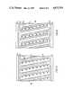
- FIG. 5is a plan view of a dot matrix printing head of the type shown in FIG. 3;
- FIG. 6is a plan view of a dot matrix printing head of the type shown in FIG. 4;
- FIG. 7is a partial sectional schematic view of an electrostatic printing head according to yet another embodiment of the invention.
- FIG. 8is a plan view of the printing head of FIG. 7.
- FIG. 3shows in somewhat schematic form a single ion projection site of a printing head 30, located adjacent an imaging member 100 to form latent electrostatic images on a dielectric surface layer 110.
- the printing head 30includes a control electrode 13 and driver electrode 12, placed on opposite sides of a solid dielectric member 11; a screen electrode 21 which is separated from the control electrode 13 by dielectric spacer layer 23; and a deflection electrode 31 which is electrically isolated from screen electrode 21 by dielectric spacer layer 33.
- Ionsare formed in the air region 13-h defined by control electrode 13 and dielectric 11 by virtue of a high voltage timevarying potential 14 imposed between the control electrode 13 and driver electrode 12.
- ions of a predetermined polarityare attracted from air region 13-h toward imaging surface 110 due to the direct current "control potential" 17 placed between control electrode 13 and counterelectrode 105.
- ion flowis modulated by the influence of screen electrode 21 (which receives screen potential 28) as is the case in the apparatus of U.S. Pat. No. 4,160,257; and in the device of FIG. 3 is subject to the further electrostatic influence of deflection electrode 31 which is located at one side of the ion path.
- Deflection electrode 31receives the direct current "deflection potential" 37, which provides a number of significant effects in determining the electrographic imaging characteristics of the device 30.
- V C , V S , and V Dto signify respectively the control, screen, and deflection potentials, it is generally advantageous that these potentials be of like polarity and of respectively decreasing amplitude (considering the counterelectrode 105 as grounded) in order to permit passage of the ion stream to the dielectric receptor surface 110.
- the deflection potential 37may be regulated so that the deflection electrode 31 repels, attracts, or acts neutrally toward the ion stream emerging from screen aperture 22.
- the deflection field arising from electrode 31produces additional effects which must be taken into consideration in the operation of this device.
- This fieldmay cause a net increase or decrease of the accelerating field which attracts ions toward dielectric surface 110, and accordingly may cause an enlargement or contraction of the resulting electrostatic iamging.
- the control voltage V Cmay be increased to restore the image to its desired size.
- the deflection electrodemay totally cut off the flow of ions.
- the apparatus of the inventionmay be operated in an analog mode, to provide a continuous range of image locations, or a switching mode, to provide two, or a limited number, of alternative image locations.
- these electrographic printing headsWhen operated in the latter arrangement, these electrographic printing heads generate predefined digital rasters with simplified, economical requirements for the control electronics, due to the additional level of multiplexing achieved by the deflection electrodes.
- FIG. 4gives a partial schematic sectional view of an ion-emitting print head 40 according to a further embodiment of the invention.
- that of FIG. 4adds an additional deflection electrode on the opposite side of the ion path; electrodes 41 and 43 each receive and independent deflection potential, respectively provided by sources 46, 48.
- Deflection potentials V D1 and V D2create a push-pull electrostatic effect on the intervening ion stream, whereby any deflection of the ions is attributable to the influence of both electrodes.
- This embodimentthereby reduces or eliminates the tendency toward enlargement or contraction of the electrostatic image as a function of the image placement.
- FIG. 5shows in a partial plan view an advantageous design of dot matrix printing head 30' utilizing the electrode arrangement of FIG. 3.
- Printing head 30'here viewed from the direction of ion projection, includes columns of screen apertures 22 in an array of screen electrodes 21, which are seen within elongated slots 39 defined by an integral deflection electrode 31.
- FIG. 6is a partial plan view of a dot matrix printing head 40' of the type shown in section in FIG. 4.
- Printing head 40'includes an array of interleaved deflection electrodes 41 and 43, placed astride columns of screen apertures 22.
- FIGS. 7 and 8illustrate an alternative ion-deflection scheme according to the invention.
- ion projection device 50includes the same control electrode 13, driver electrodes 12, and solid dielectric 11 as incorporated in the apparatus discussed above.
- Ion generator 50substitutes for the single screen electrode 22 of FIGS. 2-6, split electrodes 51, 53. Electrodes A given pair of split screen electrodes 51c, 53c are electrically isolated from each other and receive distinct screen potentials V S1 V S2 respectively provided by sources 56 and 58. Ions generaed in the air region 56 are extracted due to the accelerating field generated by the control potential V C , subject to the influence of opposing screen electrodes 53b, 51c. Providing a potential difference between the opposing screen potentials creates a net deflection field, thereby inducing a transverse component B or C in the ion projection course.
- FIG. 8shows in a plan view a matrix printing head 50' utilizing the electrode geometry of FIG. 7.
- Printing head 50'icorporates an array of interleaved screen fingers 51, 53 supported by dielectric spacer blocks 59a, 59b, etc. Ions are generated at selected crossover sites of control lines 13 and drive lines 12, and extracted subject to the moderating influence of a pair of opposing screen electrodes 51, 53, as discussed above.
- FIG. 9illustrates an alternative deflection electrode geometry in a partial plan view of a printing head 60', of particularly utility in connection with the digital raster scan arrangement of commonly assigned U.S. Ser. No. 446,821.
- Printing head 60'incorporates an array of stepped deflection electrodes 61. Individual steps 69 of deflection electrodes 61 are oriented perpendicularly to corresponding drive lines 12 (shown in phantom) on the opposite face of printing head 60. The ion generation sites of a given drive line 12 are energized simultaneously to effect ion deposition on the dielectric surface 100 (FIG. 2).
- Control electrodes 13are oriented at an acute angle with respect to drive lines 12 inasmuch as printing head 60 moves relative to the imaging surface 100 to provide a compensating offset of the ion deposition locations, as described in Ser. No. 446,821. It is therefore desirable to provide a stepped profile of deflection electrodes 61 in order that individual steps 69 will be perpendicular to the raster axes defined by drive lines 12.
Landscapes
- Physics & Mathematics (AREA)
- General Physics & Mathematics (AREA)
- Printers Or Recording Devices Using Electromagnetic And Radiation Means (AREA)
- Electrophotography Using Other Than Carlson'S Method (AREA)
Abstract
Description
Claims (12)
Priority Applications (1)
| Application Number | Priority Date | Filing Date | Title |
|---|---|---|---|
| US06/642,626US4675703A (en) | 1984-08-20 | 1984-08-20 | Multi-electrode ion generating system for electrostatic images |
Applications Claiming Priority (1)
| Application Number | Priority Date | Filing Date | Title |
|---|---|---|---|
| US06/642,626US4675703A (en) | 1984-08-20 | 1984-08-20 | Multi-electrode ion generating system for electrostatic images |
Publications (1)
| Publication Number | Publication Date |
|---|---|
| US4675703Atrue US4675703A (en) | 1987-06-23 |
Family
ID=24577356
Family Applications (1)
| Application Number | Title | Priority Date | Filing Date |
|---|---|---|---|
| US06/642,626Expired - Fee RelatedUS4675703A (en) | 1984-08-20 | 1984-08-20 | Multi-electrode ion generating system for electrostatic images |
Country Status (1)
| Country | Link |
|---|---|
| US (1) | US4675703A (en) |
Cited By (52)
| Publication number | Priority date | Publication date | Assignee | Title |
|---|---|---|---|---|
| EP0243348A4 (en)* | 1985-10-15 | 1989-07-25 | Dennison Mfg Co | Multi-electrode ion generating system for electrostatic images. |
| US4875062A (en)* | 1988-12-27 | 1989-10-17 | Eastman Kodak Company | Ion projection print head |
| EP0340998A3 (en)* | 1988-05-02 | 1990-09-05 | Xerox Corporation | Highlight color imaging by depositing positive and negative ions on a substrate |
| US4972212A (en)* | 1989-06-22 | 1990-11-20 | Xerox Corporation | Method and apparatus for controlling ion trajectory perturbations in ionographic devices |
| US4973994A (en)* | 1989-10-30 | 1990-11-27 | Xerox Corporation | Method and apparatus for controlling ion trajectory perturbations in ionographic devices |
| US5170189A (en)* | 1990-08-07 | 1992-12-08 | Fuji Xerox Co., Ltd. | Electrostatic latent image forming device with integral feeder terminal connection |
| US5206670A (en)* | 1990-11-28 | 1993-04-27 | Olympus Optical Co., Ltd. | Ion current control head |
| US5257045A (en)* | 1992-05-26 | 1993-10-26 | Xerox Corporation | Ionographic printing with a focused ion stream |
| US5278588A (en)* | 1991-05-17 | 1994-01-11 | Delphax Systems | Electrographic printing device |
| US5325121A (en)* | 1992-12-18 | 1994-06-28 | Xerox Corporation | Method and apparatus for correction of focusing artifacts in ionographic devices |
| US5450115A (en)* | 1994-10-31 | 1995-09-12 | Xerox Corporation | Apparatus for ionographic printing with a focused ion stream |
| US5508727A (en)* | 1991-05-08 | 1996-04-16 | Imagine, Ltd. | Apparatus and method for pattern generation on a dielectric substrate |
| US5617129A (en)* | 1994-10-27 | 1997-04-01 | Xerox Corporation | Ionographic printing with a focused ion stream controllable in two dimensions |
| WO1997035725A1 (en)* | 1996-03-22 | 1997-10-02 | Array Printers Ab | Method for improving the printing quality of an image recording apparatus and device for accomplishing the method |
| WO1998024634A1 (en)* | 1996-12-05 | 1998-06-11 | Array Printers Ab | Direct electrostatic printing method (dep) utilizing toner particle deflection and a printhead structure for accomplishing the method |
| US5818480A (en)* | 1995-02-14 | 1998-10-06 | Array Printers Ab | Method and apparatus to control electrodes in a print unit |
| US5818490A (en)* | 1996-05-02 | 1998-10-06 | Array Printers Ab | Apparatus and method using variable control signals to improve the print quality of an image recording apparatus |
| US5841457A (en)* | 1996-06-24 | 1998-11-24 | Xerox Corporation | Ion stream splitting and pre-focusing |
| US5889542A (en)* | 1996-11-27 | 1999-03-30 | Array Printers Publ. Ab | Printhead structure for direct electrostatic printing |
| US5933177A (en)* | 1992-12-07 | 1999-08-03 | Moore Business Forms, Inc. | Erase unit for ion deposition web-fed print engine |
| US5956064A (en)* | 1996-10-16 | 1999-09-21 | Array Printers Publ. Ab | Device for enhancing transport of proper polarity toner in direct electrostatic printing |
| US5959648A (en)* | 1996-11-27 | 1999-09-28 | Array Printers Ab | Device and a method for positioning an array of control electrodes in a printhead structure for direct electrostatic printing |
| US5966152A (en)* | 1996-11-27 | 1999-10-12 | Array Printers Ab | Flexible support apparatus for dynamically positioning control units in a printhead structure for direct electrostatic printing |
| US5971526A (en)* | 1996-04-19 | 1999-10-26 | Array Printers Ab | Method and apparatus for reducing cross coupling and dot deflection in an image recording apparatus |
| US6000786A (en)* | 1995-09-19 | 1999-12-14 | Array Printers Publ. Ab | Method and apparatus for using dual print zones to enhance print quality |
| US6011944A (en)* | 1996-12-05 | 2000-01-04 | Array Printers Ab | Printhead structure for improved dot size control in direct electrostatic image recording devices |
| US6012801A (en)* | 1997-02-18 | 2000-01-11 | Array Printers Ab | Direct printing method with improved control function |
| US6017115A (en)* | 1997-06-09 | 2000-01-25 | Array Printers Ab | Direct printing method with improved control function |
| US6017116A (en)* | 1994-09-19 | 2000-01-25 | Array Printers Ab | Method and device for feeding toner particles in a printer unit |
| US6028615A (en)* | 1997-05-16 | 2000-02-22 | Sarnoff Corporation | Plasma discharge emitter device and array |
| US6027206A (en)* | 1997-12-19 | 2000-02-22 | Array Printers Ab | Method and apparatus for cleaning the printhead structure during direct electrostatic printing |
| US6030070A (en)* | 1997-12-19 | 2000-02-29 | Array Printers Ab | Direct electrostatic printing method and apparatus |
| US6062676A (en)* | 1994-12-15 | 2000-05-16 | Array Printers Ab | Serial printing system with direct deposition of powder particles |
| US6070967A (en)* | 1997-12-19 | 2000-06-06 | Array Printers Ab | Method and apparatus for stabilizing an intermediate image receiving member during direct electrostatic printing |
| US6074045A (en)* | 1998-03-04 | 2000-06-13 | Array Printers Ab | Printhead structure in an image recording device |
| US6081283A (en)* | 1998-03-19 | 2000-06-27 | Array Printers Ab | Direct electrostatic printing method and apparatus |
| US6082850A (en)* | 1998-03-19 | 2000-07-04 | Array Printers Ab | Apparatus and method for controlling print density in a direct electrostatic printing apparatus by adjusting toner flow with regard to relative positioning of rows of apertures |
| US6086186A (en)* | 1997-12-19 | 2000-07-11 | Array Printers Ab | Apparatus for positioning a control electrode array in a direct electrostatic printing device |
| US6102526A (en)* | 1997-12-12 | 2000-08-15 | Array Printers Ab | Image forming method and device utilizing chemically produced toner particles |
| US6102525A (en)* | 1998-03-19 | 2000-08-15 | Array Printers Ab | Method and apparatus for controlling the print image density in a direct electrostatic printing apparatus |
| US6109730A (en)* | 1997-03-10 | 2000-08-29 | Array Printers Ab Publ. | Direct printing method with improved control function |
| US6132029A (en)* | 1997-06-09 | 2000-10-17 | Array Printers Ab | Direct printing method with improved control function |
| US6174048B1 (en) | 1998-03-06 | 2001-01-16 | Array Printers Ab | Direct electrostatic printing method and apparatus with apparent enhanced print resolution |
| US6199971B1 (en) | 1998-02-24 | 2001-03-13 | Arrray Printers Ab | Direct electrostatic printing method and apparatus with increased print speed |
| US6209990B1 (en) | 1997-12-19 | 2001-04-03 | Array Printers Ab | Method and apparatus for coating an intermediate image receiving member to reduce toner bouncing during direct electrostatic printing |
| US6257708B1 (en) | 1997-12-19 | 2001-07-10 | Array Printers Ab | Direct electrostatic printing apparatus and method for controlling dot position using deflection electrodes |
| US6260955B1 (en) | 1996-03-12 | 2001-07-17 | Array Printers Ab | Printing apparatus of toner-jet type |
| EP1145275A1 (en)* | 1999-01-05 | 2001-10-17 | Applied Materials, Inc. | Apparatus and method for monitoring and tuning an ion beam in ion implantation apparatus |
| US6361147B1 (en) | 1998-06-15 | 2002-03-26 | Array Printers Ab | Direct electrostatic printing method and apparatus |
| US6361148B1 (en) | 1998-06-15 | 2002-03-26 | Array Printers Ab | Direct electrostatic printing method and apparatus |
| US6406132B1 (en) | 1996-03-12 | 2002-06-18 | Array Printers Ab | Printing apparatus of toner jet type having an electrically screened matrix unit |
| WO2012017268A1 (en) | 2010-08-04 | 2012-02-09 | Triakon Nv | Print head element, print head and ionographic printing apparatus |
Citations (2)
| Publication number | Priority date | Publication date | Assignee | Title |
|---|---|---|---|---|
| US4365549A (en)* | 1978-12-14 | 1982-12-28 | Dennison Manufacturing Company | Electrostatic transfer printing |
| US4495508A (en)* | 1980-11-05 | 1985-01-22 | Konishiroku Photo Industry Co., Ltd. | Electrostatic reproducing apparatus |
- 1984
- 1984-08-20USUS06/642,626patent/US4675703A/ennot_activeExpired - Fee Related
Patent Citations (2)
| Publication number | Priority date | Publication date | Assignee | Title |
|---|---|---|---|---|
| US4365549A (en)* | 1978-12-14 | 1982-12-28 | Dennison Manufacturing Company | Electrostatic transfer printing |
| US4495508A (en)* | 1980-11-05 | 1985-01-22 | Konishiroku Photo Industry Co., Ltd. | Electrostatic reproducing apparatus |
Cited By (56)
| Publication number | Priority date | Publication date | Assignee | Title |
|---|---|---|---|---|
| EP0243348A4 (en)* | 1985-10-15 | 1989-07-25 | Dennison Mfg Co | Multi-electrode ion generating system for electrostatic images. |
| EP0340998A3 (en)* | 1988-05-02 | 1990-09-05 | Xerox Corporation | Highlight color imaging by depositing positive and negative ions on a substrate |
| US4875062A (en)* | 1988-12-27 | 1989-10-17 | Eastman Kodak Company | Ion projection print head |
| US4972212A (en)* | 1989-06-22 | 1990-11-20 | Xerox Corporation | Method and apparatus for controlling ion trajectory perturbations in ionographic devices |
| US4973994A (en)* | 1989-10-30 | 1990-11-27 | Xerox Corporation | Method and apparatus for controlling ion trajectory perturbations in ionographic devices |
| US5170189A (en)* | 1990-08-07 | 1992-12-08 | Fuji Xerox Co., Ltd. | Electrostatic latent image forming device with integral feeder terminal connection |
| US5206670A (en)* | 1990-11-28 | 1993-04-27 | Olympus Optical Co., Ltd. | Ion current control head |
| US5508727A (en)* | 1991-05-08 | 1996-04-16 | Imagine, Ltd. | Apparatus and method for pattern generation on a dielectric substrate |
| US5278588A (en)* | 1991-05-17 | 1994-01-11 | Delphax Systems | Electrographic printing device |
| US5257045A (en)* | 1992-05-26 | 1993-10-26 | Xerox Corporation | Ionographic printing with a focused ion stream |
| US5933177A (en)* | 1992-12-07 | 1999-08-03 | Moore Business Forms, Inc. | Erase unit for ion deposition web-fed print engine |
| US5325121A (en)* | 1992-12-18 | 1994-06-28 | Xerox Corporation | Method and apparatus for correction of focusing artifacts in ionographic devices |
| US6017116A (en)* | 1994-09-19 | 2000-01-25 | Array Printers Ab | Method and device for feeding toner particles in a printer unit |
| US5617129A (en)* | 1994-10-27 | 1997-04-01 | Xerox Corporation | Ionographic printing with a focused ion stream controllable in two dimensions |
| US5450115A (en)* | 1994-10-31 | 1995-09-12 | Xerox Corporation | Apparatus for ionographic printing with a focused ion stream |
| US6062676A (en)* | 1994-12-15 | 2000-05-16 | Array Printers Ab | Serial printing system with direct deposition of powder particles |
| US5818480A (en)* | 1995-02-14 | 1998-10-06 | Array Printers Ab | Method and apparatus to control electrodes in a print unit |
| US6000786A (en)* | 1995-09-19 | 1999-12-14 | Array Printers Publ. Ab | Method and apparatus for using dual print zones to enhance print quality |
| US6260955B1 (en) | 1996-03-12 | 2001-07-17 | Array Printers Ab | Printing apparatus of toner-jet type |
| US6406132B1 (en) | 1996-03-12 | 2002-06-18 | Array Printers Ab | Printing apparatus of toner jet type having an electrically screened matrix unit |
| CN1083344C (en)* | 1996-03-22 | 2002-04-24 | 排列印刷机Ab | Method for improving printing quality of image recording apparatus and device for accomplishing same method |
| US5847733A (en)* | 1996-03-22 | 1998-12-08 | Array Printers Ab Publ. | Apparatus and method for increasing the coverage area of a control electrode during direct electrostatic printing |
| WO1997035725A1 (en)* | 1996-03-22 | 1997-10-02 | Array Printers Ab | Method for improving the printing quality of an image recording apparatus and device for accomplishing the method |
| US5971526A (en)* | 1996-04-19 | 1999-10-26 | Array Printers Ab | Method and apparatus for reducing cross coupling and dot deflection in an image recording apparatus |
| US5818490A (en)* | 1996-05-02 | 1998-10-06 | Array Printers Ab | Apparatus and method using variable control signals to improve the print quality of an image recording apparatus |
| US5841457A (en)* | 1996-06-24 | 1998-11-24 | Xerox Corporation | Ion stream splitting and pre-focusing |
| US5956064A (en)* | 1996-10-16 | 1999-09-21 | Array Printers Publ. Ab | Device for enhancing transport of proper polarity toner in direct electrostatic printing |
| US5966152A (en)* | 1996-11-27 | 1999-10-12 | Array Printers Ab | Flexible support apparatus for dynamically positioning control units in a printhead structure for direct electrostatic printing |
| US5959648A (en)* | 1996-11-27 | 1999-09-28 | Array Printers Ab | Device and a method for positioning an array of control electrodes in a printhead structure for direct electrostatic printing |
| US5889542A (en)* | 1996-11-27 | 1999-03-30 | Array Printers Publ. Ab | Printhead structure for direct electrostatic printing |
| US5984456A (en)* | 1996-12-05 | 1999-11-16 | Array Printers Ab | Direct printing method utilizing dot deflection and a printhead structure for accomplishing the method |
| US6011944A (en)* | 1996-12-05 | 2000-01-04 | Array Printers Ab | Printhead structure for improved dot size control in direct electrostatic image recording devices |
| WO1998024634A1 (en)* | 1996-12-05 | 1998-06-11 | Array Printers Ab | Direct electrostatic printing method (dep) utilizing toner particle deflection and a printhead structure for accomplishing the method |
| US6012801A (en)* | 1997-02-18 | 2000-01-11 | Array Printers Ab | Direct printing method with improved control function |
| US6176568B1 (en) | 1997-02-18 | 2001-01-23 | Array Printers Ab | Direct printing method with improved control function |
| US6109730A (en)* | 1997-03-10 | 2000-08-29 | Array Printers Ab Publ. | Direct printing method with improved control function |
| US6028615A (en)* | 1997-05-16 | 2000-02-22 | Sarnoff Corporation | Plasma discharge emitter device and array |
| US6017115A (en)* | 1997-06-09 | 2000-01-25 | Array Printers Ab | Direct printing method with improved control function |
| US6132029A (en)* | 1997-06-09 | 2000-10-17 | Array Printers Ab | Direct printing method with improved control function |
| US6102526A (en)* | 1997-12-12 | 2000-08-15 | Array Printers Ab | Image forming method and device utilizing chemically produced toner particles |
| US6027206A (en)* | 1997-12-19 | 2000-02-22 | Array Printers Ab | Method and apparatus for cleaning the printhead structure during direct electrostatic printing |
| US6257708B1 (en) | 1997-12-19 | 2001-07-10 | Array Printers Ab | Direct electrostatic printing apparatus and method for controlling dot position using deflection electrodes |
| US6086186A (en)* | 1997-12-19 | 2000-07-11 | Array Printers Ab | Apparatus for positioning a control electrode array in a direct electrostatic printing device |
| US6070967A (en)* | 1997-12-19 | 2000-06-06 | Array Printers Ab | Method and apparatus for stabilizing an intermediate image receiving member during direct electrostatic printing |
| US6030070A (en)* | 1997-12-19 | 2000-02-29 | Array Printers Ab | Direct electrostatic printing method and apparatus |
| US6209990B1 (en) | 1997-12-19 | 2001-04-03 | Array Printers Ab | Method and apparatus for coating an intermediate image receiving member to reduce toner bouncing during direct electrostatic printing |
| US6199971B1 (en) | 1998-02-24 | 2001-03-13 | Arrray Printers Ab | Direct electrostatic printing method and apparatus with increased print speed |
| US6074045A (en)* | 1998-03-04 | 2000-06-13 | Array Printers Ab | Printhead structure in an image recording device |
| US6174048B1 (en) | 1998-03-06 | 2001-01-16 | Array Printers Ab | Direct electrostatic printing method and apparatus with apparent enhanced print resolution |
| US6081283A (en)* | 1998-03-19 | 2000-06-27 | Array Printers Ab | Direct electrostatic printing method and apparatus |
| US6102525A (en)* | 1998-03-19 | 2000-08-15 | Array Printers Ab | Method and apparatus for controlling the print image density in a direct electrostatic printing apparatus |
| US6082850A (en)* | 1998-03-19 | 2000-07-04 | Array Printers Ab | Apparatus and method for controlling print density in a direct electrostatic printing apparatus by adjusting toner flow with regard to relative positioning of rows of apertures |
| US6361147B1 (en) | 1998-06-15 | 2002-03-26 | Array Printers Ab | Direct electrostatic printing method and apparatus |
| US6361148B1 (en) | 1998-06-15 | 2002-03-26 | Array Printers Ab | Direct electrostatic printing method and apparatus |
| EP1145275A1 (en)* | 1999-01-05 | 2001-10-17 | Applied Materials, Inc. | Apparatus and method for monitoring and tuning an ion beam in ion implantation apparatus |
| WO2012017268A1 (en) | 2010-08-04 | 2012-02-09 | Triakon Nv | Print head element, print head and ionographic printing apparatus |
Similar Documents
| Publication | Publication Date | Title |
|---|---|---|
| US4675703A (en) | Multi-electrode ion generating system for electrostatic images | |
| US4409604A (en) | Electrostatic imaging device | |
| US4160257A (en) | Three electrode system in the generation of electrostatic images | |
| EP0752317B1 (en) | Toner projection printer with means to reduce toner spreading | |
| US5818490A (en) | Apparatus and method using variable control signals to improve the print quality of an image recording apparatus | |
| US4155093A (en) | Method and apparatus for generating charged particles | |
| US4558334A (en) | Electrostatic imaging device | |
| JPH0635274A (en) | Ionographic printing by focused ion corrent | |
| US4763141A (en) | Printing apparatus with improved ion focus | |
| US4495508A (en) | Electrostatic reproducing apparatus | |
| US4875062A (en) | Ion projection print head | |
| US4899186A (en) | Ionographic device with pin array coronode | |
| US4996425A (en) | Method and apparatus for increasing corona efficiency in an ionographic imaging device | |
| US5245502A (en) | Semi-conductor corona generator for production of ions to charge a substrate | |
| WO1987002452A1 (en) | Multi-electrode ion generating system for electrostatic images | |
| US4819013A (en) | Ion generation compensation | |
| US4794254A (en) | Distributed resistance corona charging device | |
| JPH0262862B2 (en) | ||
| US4068585A (en) | Electrostatic printer support with controlled electrostatic surface voltage | |
| US5083145A (en) | Non-arcing blade printer | |
| EP0753412B1 (en) | Toner projection printer with improved address electrode structure | |
| US4951071A (en) | Resistive nib ionographic imaging head | |
| US6176568B1 (en) | Direct printing method with improved control function | |
| US5912692A (en) | Printing device with M-tunnel write head | |
| US4879569A (en) | Multiple source charged particle generation |
Legal Events
| Date | Code | Title | Description |
|---|---|---|---|
| AS | Assignment | Owner name:DENNISON MANUFACTURING COMPANY FRAMINGHAM, MA A CO Free format text:ASSIGNMENT OF ASSIGNORS INTEREST.;ASSIGNOR:FOTLAND, RICHARD A.;REEL/FRAME:004303/0718 Effective date:19840817 | |
| AS | Assignment | Owner name:DELPHAX SYSTEMS, RANDOLPH, MASSACHUSETTS A PARTNER Free format text:ASSIGNMENT OF ASSIGNORS INTEREST.;ASSIGNOR:DENNISON MANUFACTURING COMPANY;REEL/FRAME:004841/0517 Effective date:19870828 Owner name:DELPHAX SYSTEMS, A PARTNERSHIP OF MA,MASSACHUSET Free format text:ASSIGNMENT OF ASSIGNORS INTEREST;ASSIGNOR:DENNISON MANUFACTURING COMPANY;REEL/FRAME:004841/0517 Effective date:19870828 | |
| FEPP | Fee payment procedure | Free format text:PAYOR NUMBER ASSIGNED (ORIGINAL EVENT CODE: ASPN); ENTITY STATUS OF PATENT OWNER: LARGE ENTITY | |
| REMI | Maintenance fee reminder mailed | ||
| LAPS | Lapse for failure to pay maintenance fees | ||
| STCH | Information on status: patent discontinuation | Free format text:PATENT EXPIRED DUE TO NONPAYMENT OF MAINTENANCE FEES UNDER 37 CFR 1.362 | |
| FP | Lapsed due to failure to pay maintenance fee | Effective date:19910623 |