US4674500A - Sheathed knife instrument - Google Patents
Sheathed knife instrumentDownload PDFInfo
- Publication number
- US4674500A US4674500AUS06/780,895US78089585AUS4674500AUS 4674500 AUS4674500 AUS 4674500AUS 78089585 AUS78089585 AUS 78089585AUS 4674500 AUS4674500 AUS 4674500A
- Authority
- US
- United States
- Prior art keywords
- blade
- sheath
- end portion
- instrument
- elongate
- Prior art date
- Legal status (The legal status is an assumption and is not a legal conclusion. Google has not performed a legal analysis and makes no representation as to the accuracy of the status listed.)
- Expired - Lifetime
Links
- 239000012530fluidSubstances0.000claimsdescription23
- 230000000717retained effectEffects0.000claimsdescription7
- 230000004308accommodationEffects0.000claimsdescription3
- 230000007246mechanismEffects0.000claimsdescription3
- 230000004044responseEffects0.000claimsdescription3
- 238000005520cutting processMethods0.000description15
- 210000003811fingerAnatomy0.000description7
- 238000000034methodMethods0.000description6
- 238000001356surgical procedureMethods0.000description6
- 230000000712assemblyEffects0.000description3
- 238000000429assemblyMethods0.000description3
- 230000000694effectsEffects0.000description3
- 230000006870functionEffects0.000description3
- 210000003813thumbAnatomy0.000description3
- 238000003780insertionMethods0.000description2
- 230000037431insertionEffects0.000description2
- 230000014759maintenance of locationEffects0.000description2
- 230000001681protective effectEffects0.000description2
- 239000000523sampleSubstances0.000description2
- 238000007789sealingMethods0.000description2
- 230000006978adaptationEffects0.000description1
- 238000010276constructionMethods0.000description1
- 239000000463materialSubstances0.000description1
- 239000002184metalSubstances0.000description1
- 210000002445nippleAnatomy0.000description1
- 230000009993protective functionEffects0.000description1
- 230000008719thickeningEffects0.000description1
- 238000009966trimmingMethods0.000description1
Images

Classifications
- A—HUMAN NECESSITIES
- A61—MEDICAL OR VETERINARY SCIENCE; HYGIENE
- A61B—DIAGNOSIS; SURGERY; IDENTIFICATION
- A61B17/00—Surgical instruments, devices or methods
- A61B17/32—Surgical cutting instruments
- A—HUMAN NECESSITIES
- A61—MEDICAL OR VETERINARY SCIENCE; HYGIENE
- A61B—DIAGNOSIS; SURGERY; IDENTIFICATION
- A61B17/00—Surgical instruments, devices or methods
- A61B17/32—Surgical cutting instruments
- A61B17/3209—Incision instruments
- A61B17/3211—Surgical scalpels, knives; Accessories therefor
- A—HUMAN NECESSITIES
- A61—MEDICAL OR VETERINARY SCIENCE; HYGIENE
- A61B—DIAGNOSIS; SURGERY; IDENTIFICATION
- A61B17/00—Surgical instruments, devices or methods
- A61B17/32—Surgical cutting instruments
- A61B17/320016—Endoscopic cutting instruments, e.g. arthroscopes, resectoscopes
Definitions
- the present inventionis broadly directed to surgical instruments, and more specifically to instruments useful in arthroscopic surgery and similar surgical procedures wherein access to the surgical site is limited and/or difficult.
- the surgical environment of the inventionnormally involves performance of surgical procedures through small incisions through which the instruments are introduced and subsequently manipulated.
- surgical cutting instrumentsfor example cutting blades
- substantial caremust be taken not only in the cutting manipulation thereof, but also in the actual introduction of the cutting blade to the cutting site and the subsequent removal therefrom.
- the instrument in Roberts et alis limited in its use in that the guided nature of the blade enables use of the blade only for a removal or slicing of material from a surface. It cannot be used to make a perpendicular cut. Further, the instrument itself is rather cumbersome, requiring the use of two handles to adjust the wire shape and position, after which the blade has to be moved forward in a separate motion.
- the Le Noir instrumenthas been devised for a specific procedure, and is not readily adaptable for general cutting purposes in either arthroscopic surgery or other surgery. Further, the tool itself is rather cumbersome and utilizes two insertions to position and align the opposed guide grooves to carry the flexible blade therebetween.
- the surgical instrument of the present inventionis unique in its provision of a sheath protected blade wherein the sheath, in addition to performing its protective function, is configured, along the distal end portion, to both guide and direct a received blade along a preselected laterally curving path.
- the guided leading tip and end portion of the bladebe extended and operable beyond the confines of the guide structure of the sheath while maintaining the preselected guided path defined by the distal end portion of the sheath.
- the operative end of the bladeis completely exposed for free use of its tip and/or edge as required by the particular procedure.
- the complete exposure of the operating end portion of the bladewhile providing for a positive guidance thereof along for example an arcuate path, provides for not only an exact positioning of the blade, but also, as desired, a guided cutting motion as the blade is slid out of the sheath and along the guided path.
- the sheathed knife instrument of the inventionprovides a reusable handle and actuation mechanism in conjunction with removable, disposable single use sheathed knife blades.
- the sheathed bladesare easily interchangeable and can be provided with a variety of different blade guiding curvatures at the distal ends of the sheaths. Similarly, variations in blade widths and tip shapes can be easily provided by provision of appropriately configured sheath and blade combination assemblies interchangeably mountable on the handle.
- the construction of the surgical instrumentinvolves two basic modules, the reusable handle and the disposable combination sheath and blade.
- the reusable handleis a small, round elongate cylindrical tube easily grasped and manipulated by one hand.
- An elongate cylindrical tubular slideris mounted for reciprocation within the main cylindrical body of the tube.
- the internal slideris connected to an external slide button whereby the handle can be held in one hand and the external button actuated either by the thumb or an index finger for a selective reciprocation of the internal slider.
- a valve and tube fittingwill be incorporated in the rear section of the handle.
- the desired flowwill be effected through the tubular handle and tubular internal slider. Appropriate seals will of course be provided.
- the handle assembly or modulealso includes a retaining cap mounted on the front or forward section thereof and used to removably retain the disposable sheathed blade.
- the disposable sheathed bladeis a two-part assembly comprising the blade and the surrounding sheath.
- the rear or proximal portion of the sheathis configured for positioning within the front or forward section of the handle for retention by the retaining cap.
- the forward or distal portion of the sheathwill preferably be of either a flattened or a tubular configuration, in each instance following a lateral arcuate curvature corresponding to the guided direction desired for the blade.
- the flattened end configurationallows for access to smaller areas along with higher fluid velocities.
- the tubular or unflattened cylindrical end portionprovides for higher fluid flows. Either configuration can be given any curvature.
- the elongate flexible bladeis slidably received within the sheath and, when extended, follows the sheath curvature.
- the flexible nature of the bladeenables the blade to assume the curvature of the sheath and retain this curvature as the leading end portion of the blade is extended from the sheath.
- the blademay be formed with a predisposition to assume the particular curvature of the sheath with which it is associated.
- the bladeat the rear or proximal end thereof, includes a laterally directed tab which is removably positioned within the leading end of the slider for a manipulation of the blade in response to sliding movement of the slider.
- the rear or proximal end of the sheathis, in turn, retained to the leading end of the handle by the retaining cap with the blade movable relative thereto.
- Replacement of the blade and sheath combinationrequires only a removal of the retaining cap and a disengagement of the blade. A new assembly is then inserted into place and the retaining cap remounted.
- the leading portion of the blade or blade tipcan be provided with any appropriate surgical configuration.
- the blade and sheath assembliescan be made to any necessary blade width and any desired operating curvature.
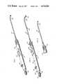
- FIG. 1is a perspective view of the sheathed knife instrument of the present invention with the blade retracted;
- FIG. 2is a perspective view similar to FIG. 1 with the blade extended;
- FIG. 3is a partial perspective view of the forward portion of the instrument wherein the sheath is provided with a cylindrical forward guide portion;
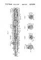
- FIG. 4is an enlarged longitudinal cross-section through the instrument with forward portions of the sheath and blade broken away;
- FIG. 5is a cross-sectional detail taken substantially on a plane passing along line 5--5 in FIG. 4;
- FIG. 6is a cross-sectional detail taken substantially on a plane passing along line 6--6 in FIG. 4;
- FIG. 7is a cross-sectional detail taken substantially on a plane passing along line 7--7 in FIG. 4;
- FIG. 8is a cross-sectional detail taken substantially on a plane passing along line 8--8 in FIG. 4;
- FIG. 9is a longitudinal cross-sectional view through the instrument rotated 90 degrees from the showing in FIG. 4 with the blade in its retracted position;
- FIG. 10is a longitudinal cross-sectional view rotated relative to FIG. 9 with the blade in the extended position with the valve open and the slide button locked, the button connector, for purposes of clarity, is shown in elevation;
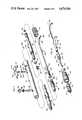
- FIG. 11is an exploded perspective view of the components of the instrument.
- FIG. 12is an exploded perspective detail of the sheath and blade module and the mounting portions of the handle module.
- reference numeral 20is used to generally designate the surgical instrument comprising the present invention.
- the instrumentprincipally a sheathed blade knife, comprises two basic modules, a reusable handle 22 and a disposable sheathed blade or combination sheath and blade 24.
- the sheathed blade 24as shall be detailed subsequently, is operably mountable to the handle for manipulation thereby. After use, the sheathed blade is removed and disposed of, while the handle is retained for reuse.
- the handle 22comprises an elongate main cylindrical tubular body 26 having rear and forward tubular sections 28 and 30 longitudinally aligned with and telescopically press fit within the rear and forward portions respectively of the main body 26.
- the press fit engagementis such as to provide a fluid tight seal, this being particularly significant in those instances wherein the instrument is also to perform an aspirator/irrigator function.
- the rear section 28will be provided with a coaxial rearwardly directed nipple 32 for engagement, through appropriate tubing, with a fluid source, vacuum chamber, or the like.
- an appropriate valvesuch as plug valve 34
- the valveis rotatably retained by a threaded retaining ring 38 engaged about the stem of the valve and threaded within an internally threaded bore in the main body 26 through which the valve 34 is introduced.
- the valve stemprojects externally of the body and mounts an appropriate valve manipulating knob 40, configured for easy grasping between the fingers of a user for rotation of the valve, in either direction, between an open and closed position.
- the gripping configuration thereofactually defines an elongate projecting rib which can be oriented on the stem of the valve to visually indicate the open and closed positions thereof.
- the proper positioning of the rear section 28 within the main body 26is provided for by interengaging or seating annular shoulder portions exteriorly about the rear section 28 and interiorly about the hollow bore of the body 26 as illustrated at 42 and 44.
- the forward or front section 30is also of a tubular open ended configuration, the hollow interior of which, designated at 46, may define a fluid passage.
- An integral annular collar 48surrounds the front section 30 at approximately midpoint along the length thereof.
- the proximal portion 50, rearward of the collar 48,is press fit within the forward end portion of the main body 26 with the rear portion of the collar 48 seated within an annular seat at the forward end of the body 26.
- the engagement of the forward section within the forward portion of the bodypreferably provides a fluid tight seal.
- the collar 48forward of the front end of the main body 26, is provided with an annular O-ring seal 52 appropriately seated within an annular retaining groove.
- the front section 30includes an exteriorly threaded portion 54.
- the front section 30, forward of the threaded portion 54includes a smooth tubular integral extension 56 terminating in an end wall with a central aperture 58 of slightly less diameter than the internal bore 46 resulting from an integral collar-like internal enlargement 60 at the forward end of front section 30.
- the tubular forward portion 56 of the front section 30includes a slot 62 extending longitudinally therein from the outer forward end and terminating in a transverse or laterally directed inner end portion immediately forward of the externally threaded portion 54, providing in effect an L-shaped slot communicating with the longitudinal interior bore 46 of the forward section 30 throughout the length of the slot.
- the slotextends through the internal thickening or collar 60 defining the forward aperture 58.
- the handle 22includes an elongate internal tubular slider 64 preferably having a hollow open-ended full length axial bore 66 adapted to accommodate fluid flow in those instances wherein the instrument is structured to provide for such flow.
- This axial bore 66will provide continuity between the passages or bores 36 and 46 of the rear and forward sections 28 and 30.
- the internal slider 64includes an elongate central portion 68 closely received within and slidable along the internal bore of the main body section 26.
- This central slider portion 68is suitably sealed to the bore wall by an appropriate O-ring seal seated within a retaining groove about the outer periphery of the central portion 68.
- the internal slider 64includes elongate reduced diameter integral and coaxial rear and forward portions 72 and 74. Each of these portions 72 and 74 define, at the corresponding end of the central portion 68, an annular external shoulder 76 and 78 respectively.
- the rear portion 72 of the internal slider 64is telescopically received within the forward portion of the fluid passage or bore 36 through the rear section 28 and is adapted for free longitudinal movement therein with rearward movement of the slider limited only by engagement of the annular shoulder 76 against the forward end 80 of the rear section 28. Such an engagement will be noted in FIGS. 4 and 9, and constitutes the innermost position of the internal slider 64.
- the rear portion 72 of the internal slider 64within the forward section of the bore 36, is surrounded by a coiled torsion spring 82 having a rear laterally directed end 84 engaged within a socket in the internal wall of the bore 36 for a positioning and retention of the spring 82.
- the second end 86 of the spring 82is laterally inwardly directed and received within an elongate slot or groove 88 in the rear portion 72 in a manner whereby the internal slider, while freely longitudinally slidable relative to the spring 82, is rotatably biased, when viewed from the rear thereof, in a clockwise direction relative to the central portion 26 of the handle.
- the forward portion 74 of the internal slider 64is telescopically receivable within the internal bore 46 of the front section 30 with forward sliding movement of the internal slider 64 being limited by engagement of the forward annular shoulder 78 against the annular inner or rear end 90 of the front section 30. This engagement will be noted in FIG. 10.
- An appropriate sealing O-ring 92is provided, within an annular recess about the forward portion 74, between the forward portion 74 and the internal wall of the bore 46 of the front section 30. This sealed relationship is maintained throughout the full longitudinal movement of the internal slider 64.
- the leading end of the forward portion 74 of the internal slider 64has a slot 94 defined therein.
- This slot 94which may communicate with the hollow interior or the interior bore 66 through the internal slider 64, extends longitudinally inward from the extreme end of the forward portion 74 and terminates, inward or rearward of the forward end, in a laterally directed extent or length 96, best noted in FIGS. 10 and 12.
- the laterally directed extent 96 of the slot 94may extend to either or both sides of the main or longitudinal extent of the slot 94.
- the slot 94upon a forward extension of the slider 64 to its extended position wherein annular shoulder 78 engages against abutment end 90 of the front section 3 , aligns with the slot 62, in front section 30, laterally inward thereof. This alignment will be noted in FIG. 10.
- Movement of the internal slider 64is achieved by a single thumb or finger manipulation of an external slider or slide button 98 overlying and conforming to the external configuration of the main handle body 26.
- an appropriate integral transverse rib 100is preferably defined thereon.
- the external button 98is rigidly coupled to the internal slider 64 by an elongate connector or connector pin 102 having the inner end portion thereof provided with external threads and threadedly engaged within an internally threaded socket within the wall of the internal slider, normally immediately rearward of the annular shoulder 78.
- the connector 102immediately outward of the internal slider, extends transversely through a longitudinally elongate slot 104 through the main body 26 of the handle 22.
- the connector 102, within the slot 104is surrounded by a bushing 106 which facilitates free sliding movement of the connector 102 along the slot 104.
- the upper or outer end of the connector 102includes an annular groove or undercut portion 108 for the reception of the inner end of an appropriate locking or set screw 110 engaged through the slide button 98 for a locking of the button 98 to the connector 102.
- the internal slider 64 and the external manipulating button 98are movable as a unit through manipulation of the button 98.
- the forward end of the connector-accommodating slot 104includes a laterally directed extent or length 112 whereby, upon a full forward extension of the button 98 and internal slider therewith, a lateral or rotational movement of the button 98 will result in a movement of the bushing-surrounded connector 102 into the lateral extent 112 and a locking of the internal slider in its forwardmost position.
- a laterally directed extent or length 112whereby, upon a full forward extension of the button 98 and internal slider therewith, a lateral or rotational movement of the button 98 will result in a movement of the bushing-surrounded connector 102 into the lateral extent 112 and a locking of the internal slider in its forwardmost position.
- the previously described torsion spring 82specifically functions to rotatably bias the internal slider 64 for movement of the connector 102 into the lateral extent 112 of the slot 104 and thus effect an automatic locking of the internal slider 64 in its forward or extended position. It is to be appreciated that this biasing force can be easily overridden by finger pressure on the slider button 98 as desired, both during actual manipulation of the instrument or at such time as a retraction of the blade is desired.
- the final component of the handle module 22is the retaining cap 114 received over and enclosing the forward projecting end portion of the front section 30.
- the capincludes an intermediate internal portion 116 internally threaded for threaded engagement with the externally threaded portion 54.
- the retaining cap 114is provided with a skirt which engages over and about the O-ring seal 52 for an internal sealing of the cap.
- the forward or outer end 118 of the cap 114has a central aperture 120 defined therethrough for an accommodation of the sheathed blade module 24.
- a positioning pin 122is engaged through the enlarged leading end of the front section 30 and projects radially into the end opening 58 for cooperation with the slider slot 94 in properly orienting the sheathed blade module 24.
- the sheathed blade module 24is a two-part assembly comprising an elongate blade 124 and a tubular sheath 126.
- the blade 124at the distal or leading end portion 128 thereof, will be of any appropriate surgical configuration, for example, a knife edge as suggested in FIGS. 2 and 11, or a transverse cutting tip as suggested in FIG. 12.
- the proximal or rear end portion 130 of the blade 124includes a gripping tab 132 defined by a lateral turning or directing of the proximal end.
- This end portion 130is particularly configured for introduction through the angled slot 62 in the front section of the handle for subsequent seated reception within the aligned angled slot or notch 94 of the forward portion 74 of the slider 64.
- the positioning of the proximal end portion 130 of the blade 124 into the slider slot 94requires a positioning of the internal slider at its forwardmost location and prior to the rotational locking thereof into the extension 112 of the slot 104 in the main body section 26.
- the tubular sheath 126will normally be of a cylindrical configuration provided with a proximal end portion 134 including a mounting end 136 and an integral seating or positioning collar 138 immediately forward thereof.
- the mounting end 136constituting an integral rearward extension of the sheath, will include one or more positioning slots 140 extending longitudinally therein and opening through the rear of the sheath 126.
- the forward or distal end portion 142 of the sheath 126is laterally arced along a predetermined curvature defining the path to be taken by the blade during extension thereof.
- This arcuate leading portion 142 of the sheath 126can, as illustrated in FIGS. 1 and 2, be flattened or, as illustrated in FIG. 3, be retained cylindrical throughout the extent thereof.
- the particular cross-sectional configuration of the leading portion 142 of the sheath 126will be determined by the circumstances and procedures involved.
- Each configurationincorporates particular advantages and will be chosen accordingly. For example, the flattened, oblong configuration, more clearly illustrated in FIGS.
- the sheathed blade assembly 24is a disposable unit with the blade 124 normally initially introduced into the sheath 126 through the rear of the sheath 126.
- the blade 124is receiprocal within the sheath for a selective complete retraction of the leading forward operational portion of the blade and a corresponding extension thereof.
- the curved leading portion 142 of the sheath 126is configured, in accord with the particular procedure, to both particularly position the extended blade and to guide the blade during the extension thereof beyond the sheath.
- the guidance of the blade during the extension thereofinsures movement of the blade along a predetermined path beyond the sheath while at the same time freely exposing the blade for cutting, trimming, etc. in a controlled manner by a finger operated manipulation of the blade and a hand manipulation of the handle.
- the sheathed blade assemblyis, in its entirety, intended to be a disposable item, readily interchangeable as desired. It is contemplated that sheathed blade assemblies, in different widths, curvatures and blade tip configurations be provided, enabling, through the interchangeable nature of the sheathed blades, a ready adaptation of the instrument as required to any particular procedure involved. As suggested in the drawings, the rear or proximal mounting end portions of the sheaths and blades will be standardized for all sheath and blade sizes to enable accommodation within single size reusable handles. Note the mounting end portion of the illustrated sheath is of a slightly greater cross-section than the cross-section of the remainder of the sheath. Similarly, the mounting end portion of the illustrated blade is of a slightly less height.
- the bladesbe of a flexible surgical metal capable of following the curvature of the leading portion 142 of the sheath and maintaining the directional orientation as the leading tip portion of the blade moves outward into operational position beyond the sheath.
- the flexible nature of the blade 124allows for a complete retraction of the blade into the sheath for a complete protective enclosing of the blade, protecting both the blade and the body tissue during both the insertion and removal of the instrument.
- the internal slider 64In mounting the removable sheathed blade assembly 24 on the handle 22, the internal slider 64 is moved to its forward position, orienting the slot or notch 94 in the leading end beneath and in alignment with the slot 62 in the leading end of the front section 50.
- the rear portion 130 of the blade 124, extended rearward of the sheath 126,is then moved through the slot 62 and into retained position within slot 94.
- the lateral tab 132 of the rear portion 130 of the blade 124seats within the lateral extent 96 of slot 94.
- the width of the tabbed rear portion of the bladeis such as to move completely through the slot 62 and seat within the slot 94 of the leading end of the internal slider 64.
- the engagement with the slideris such whereby the blade 124 will both longitudinally reciprocate and rotate with the internal slider in response to movement of the internal slider.
- the notched seat defined by the slot 94precludes all relative movement between the blade 124 and the internal slider 64 other than for a complete disengagement of the blade and a removal thereof upon an alignment of the outer slot 62 therewith.
- the mounting end 136 of the sheath 126is moved rearwardly through the aperture 58 in the front section 30 with one of the aligning notches 140, in the mounting end 136, receiving the aligning or positioning pin 122 therein. In this manner, the rotational position of the sheath 126 is fixed. Inward movement of the mounting end terminates with the positioning collar 138 seated against the end wall of the front section 30.
- the retaining cap 114either previously positioned on the sheath 126 or at this point introduced over the arcuate forward end portion 142 thereof, is moved rearwardly and threaded onto the front section 30 with the forward wall or end 118 of the cap engaging the sheath collar 138 and clamping the collar 138, and hence the sheath itself, into fixed position on the forward end of the handle assembly 22.
- the aperture 120 through the front wall of the cap 114is such as to allow for free movement over the length of the sheath, while at the same time being sufficiently restrictive to positively engage against and confine the sheath collar 138.
- the blade 124When fully assembled, the blade 124 can be readily manipulated by either the thumb or index finger of a user while the instrument is held in one hand. A retraction of the internal slider 64, through a rearward sliding of the slide button 98, retracts the blade into a protected position completely within the sheath 126. Similarly, a forward movement of the slide button 98 effects a corresponding forward movement of the internal slider 64 and an extension of the blade to project beyond the leading end of the sheath and along a path determined by the curvature of the leading portion of the sheath.
- the sheathnot only protects the blade but also guides and directs the blade whereby the extension of the blade from the sheath can actually comprise a cutting movement of the guided blade rather than merely a means for exposing the blade for subsequent manipulation.
- the userupon selection of the appropriated sheathed blade assembly with the curvature desired, properly orients the mounted sheath and then extends the blade with the blade cutting or slicing the tissue along the path of outward movement of the blade.
- the bladeitself is completely exposed, allowing for complete access thereto for use of the tip and/or edge as required and without interference from the guide structure provided by the sheath inward thereof.
- the instrumentis particularly adapted for use as a multi-functional probe, knife and aspirator/irrigator.
- the cap retained engagement of the collar 138 of the sheath 126provides a fluid seal with the sheath 126 providing an internal flow path which combines and directly communicates with the aligned flow paths through the handle assembly itself.
Landscapes
- Health & Medical Sciences (AREA)
- Life Sciences & Earth Sciences (AREA)
- Surgery (AREA)
- Heart & Thoracic Surgery (AREA)
- Engineering & Computer Science (AREA)
- Biomedical Technology (AREA)
- Nuclear Medicine, Radiotherapy & Molecular Imaging (AREA)
- Medical Informatics (AREA)
- Molecular Biology (AREA)
- Animal Behavior & Ethology (AREA)
- General Health & Medical Sciences (AREA)
- Public Health (AREA)
- Veterinary Medicine (AREA)
- Orthopedic Medicine & Surgery (AREA)
- Surgical Instruments (AREA)
Abstract
Description
Claims (22)
Priority Applications (8)
| Application Number | Priority Date | Filing Date | Title |
|---|---|---|---|
| US06/780,895US4674500A (en) | 1985-09-27 | 1985-09-27 | Sheathed knife instrument |
| CA000514539ACA1252363A (en) | 1985-09-27 | 1986-07-24 | Sheathed knife instrument |
| AU60786/86AAU589663B2 (en) | 1985-09-27 | 1986-08-01 | Sheathed knife instrument |
| JP1986128317UJPS6256014U (en) | 1985-09-27 | 1986-08-21 | |
| DE8686307371TDE3687940T2 (en) | 1985-09-27 | 1986-09-25 | CUTTER WITH SHEATH. |
| EP86307371AEP0217638B1 (en) | 1985-09-27 | 1986-09-25 | Sheathed knife instrument |
| KR1019860008063AKR940001844B1 (en) | 1985-09-27 | 1986-09-26 | Sheathed knife instrument |
| HK64395AHK64395A (en) | 1985-09-27 | 1995-04-27 | Sheathed knife instrument |
Applications Claiming Priority (1)
| Application Number | Priority Date | Filing Date | Title |
|---|---|---|---|
| US06/780,895US4674500A (en) | 1985-09-27 | 1985-09-27 | Sheathed knife instrument |
Publications (1)
| Publication Number | Publication Date |
|---|---|
| US4674500Atrue US4674500A (en) | 1987-06-23 |
Family
ID=25121022
Family Applications (1)
| Application Number | Title | Priority Date | Filing Date |
|---|---|---|---|
| US06/780,895Expired - LifetimeUS4674500A (en) | 1985-09-27 | 1985-09-27 | Sheathed knife instrument |
Country Status (8)
| Country | Link |
|---|---|
| US (1) | US4674500A (en) |
| EP (1) | EP0217638B1 (en) |
| JP (1) | JPS6256014U (en) |
| KR (1) | KR940001844B1 (en) |
| AU (1) | AU589663B2 (en) |
| CA (1) | CA1252363A (en) |
| DE (1) | DE3687940T2 (en) |
| HK (1) | HK64395A (en) |
Cited By (55)
| Publication number | Priority date | Publication date | Assignee | Title |
|---|---|---|---|---|
| US4790819A (en)* | 1987-08-24 | 1988-12-13 | American Cyanamid Company | Fibrin clot delivery device and method |
| US4880000A (en)* | 1987-12-15 | 1989-11-14 | Iolab Corporation | Lens insertion instrument |
| US4934363A (en)* | 1987-12-15 | 1990-06-19 | Iolab Corporation | Lens insertion instrument |
| US5141517A (en)* | 1990-01-16 | 1992-08-25 | Zimmer Inc. | Retractable instrument |
| US5154694A (en)* | 1989-06-06 | 1992-10-13 | Kelman Charles D | Tissue scraper device for medical use |
| DE4140402A1 (en)* | 1991-12-07 | 1993-06-09 | Dieter Prof. Dr.Med. 7700 Singen De Ruehland | Instrument for surgical intervention in stomach cavity - has sleeve tube for at least one axially movable rod with blade at operation end of instrument being controlled by rod |
| US5250065A (en)* | 1990-09-11 | 1993-10-05 | Mectra Labs, Inc. | Disposable lavage tip assembly |
| US5282816A (en)* | 1991-09-20 | 1994-02-01 | Milres Corporation | Apparatus for subligamentous endoscopic transverse carpal ligament release surgery |
| US5292330A (en)* | 1990-05-31 | 1994-03-08 | Linvatec Corporation | Retractable surgical instrument with curved operative element |
| US5306237A (en)* | 1989-11-06 | 1994-04-26 | Mectra Labs, Inc. | Disposable lavage |
| US5322055A (en)* | 1993-01-27 | 1994-06-21 | Ultracision, Inc. | Clamp coagulator/cutting system for ultrasonic surgical instruments |
| US5335671A (en)* | 1989-11-06 | 1994-08-09 | Mectra Labs, Inc. | Tissue removal assembly with provision for an electro-cautery device |
| US5338292A (en)* | 1989-11-06 | 1994-08-16 | Mectra Labs, Inc. | Disposable lavage with instrument shield |
| US5350390A (en)* | 1992-03-25 | 1994-09-27 | Arieh Sher | Device for removal of intraluminal occlusions |
| US5391177A (en)* | 1993-02-12 | 1995-02-21 | Schwartz; Daniel M. | Ophthalmic lance |
| US5403277A (en)* | 1993-01-12 | 1995-04-04 | Minnesota Mining And Manufacturing Company | Irrigation system with tubing cassette |
| US5409013A (en)* | 1989-11-06 | 1995-04-25 | Mectra Labs, Inc. | Tissue removal assembly |
| US5417654A (en)* | 1994-02-02 | 1995-05-23 | Alcon Laboratories, Inc. | Elongated curved cavitation-generating tip for disintegrating tissue |
| US5443474A (en)* | 1994-03-07 | 1995-08-22 | Implemed, Inc. | Meniscectomy knife |
| US5467684A (en)* | 1992-03-25 | 1995-11-21 | Sher; Arieh | Rotary piston driving mechanism |
| US5505210A (en)* | 1989-11-06 | 1996-04-09 | Mectra Labs, Inc. | Lavage with tissue cutting cannula |
| US5527332A (en)* | 1994-11-02 | 1996-06-18 | Mectra Labs, Inc. | Tissue cutter for surgery |
| US5571128A (en)* | 1995-07-24 | 1996-11-05 | Shapiro; Henry | Safety surgical instrument |
| EP0622050B1 (en)* | 1993-04-30 | 1997-03-05 | Eagle Vision Inc. | Microsurgical scalpel assembly |
| US5626596A (en)* | 1995-02-15 | 1997-05-06 | Questus Corporation | Tool support assembly with bidirectional position control |
| US5626563A (en)* | 1993-01-12 | 1997-05-06 | Minnesota Mining And Manufacturing Company | Irrigation system with tubing cassette |
| US5755732A (en)* | 1994-03-16 | 1998-05-26 | United States Surgical Corporation | Surgical instruments useful for endoscopic spinal procedures |
| US5776156A (en)* | 1995-09-05 | 1998-07-07 | United States Surgical Corporation | Endoscopic cutting instrument |
| US5797907A (en)* | 1989-11-06 | 1998-08-25 | Mectra Labs, Inc. | Electrocautery cutter |
| US5830226A (en)* | 1993-04-30 | 1998-11-03 | Eagle Vision, Inc. | Microsurgical scalpel assembly |
| WO1999022654A1 (en) | 1997-11-04 | 1999-05-14 | Karl Storz Gmbh & Co. | Endoscopic instrument with a cutting tool |
| DE19754781A1 (en)* | 1997-12-10 | 1999-06-24 | Premysl Dr Med Pavlicek | Surgical instrument for removing varicose veins |
| US5993409A (en)* | 1996-11-27 | 1999-11-30 | Surgin Surgical Instrumentation, Inc. | Needle for surgical use |
| US6193672B1 (en) | 1993-05-11 | 2001-02-27 | Mectra Labs, Inc. | Lavage |
| US20040102801A1 (en)* | 2002-06-04 | 2004-05-27 | Cimino William W. | Ultrasonic device and method for tissue coagulation |
| US20050033338A1 (en)* | 2003-06-19 | 2005-02-10 | Ferree Bret A. | Surgical instruments particularly suited to severing ligaments and fibrous tissues |
| US20050171470A1 (en)* | 2004-01-29 | 2005-08-04 | Cannuflow Incorporated | Atraumatic arthroscopic instrument sheath |
| US20050192532A1 (en)* | 2004-01-29 | 2005-09-01 | Kucklick Theodore R. | Atraumatic arthroscopic instrument sheath |
| US20050203342A1 (en)* | 2004-01-29 | 2005-09-15 | Cannuflow Incorporated | Atraumatic arthroscopic instrument sheath |
| US20050234298A1 (en)* | 2004-01-29 | 2005-10-20 | Cannuflow Incorporated | Atraumatic arthroscopic instrument sheath |
| US20060053640A1 (en)* | 2004-09-13 | 2006-03-16 | Huang Chun P | Windshield glue penetration device |
| US20070010823A1 (en)* | 2005-07-11 | 2007-01-11 | Cannuflow, Inc. | Arthroscopic shaver system |
| US20100125290A1 (en)* | 2008-11-20 | 2010-05-20 | Gregory Allen Auchter | Guarded surgical knife handle |
| US20100125293A1 (en)* | 2008-11-20 | 2010-05-20 | Gregory Allen Auchter | Guarded surgical knife handle |
| US20110034851A1 (en)* | 2009-02-26 | 2011-02-10 | Pierce Javin C | System for harvesting and dispensing a fibrin clot |
| US20110092919A1 (en)* | 2009-02-26 | 2011-04-21 | Pierce Javin C | Method and apparatus for harvesting and dispensing a fibrin clot |
| US20140221909A1 (en)* | 2013-01-14 | 2014-08-07 | R. Ashley Burrow | Surgical Aspiration and Irrigation |
| US20150032207A1 (en)* | 2011-04-29 | 2015-01-29 | Mark Humayun | Instruments and methods for the implantation of cell-seeded substrates |
| US9232958B2 (en) | 2012-05-16 | 2016-01-12 | Smith & Nephew, Inc. | Reusable blade hub assembly |
| US9308013B2 (en) | 2010-11-03 | 2016-04-12 | Gyrus Ent, L.L.C. | Surgical tool with sheath |
| JP2020528332A (en)* | 2017-07-22 | 2020-09-24 | リダ,ヘイダー | Suction resection device for tonsillectomy |
| US20220160220A1 (en)* | 2020-11-23 | 2022-05-26 | Medos International Sárl | Arthroscopic medical implements and assemblies |
| US11413051B2 (en) | 2017-07-25 | 2022-08-16 | Stryker European Holdings I Llc | Irrigation sleeves for use with surgical systems |
| US12070196B2 (en) | 2020-11-23 | 2024-08-27 | Medos International Sarl | Arthroscopic medical implements and assemblies |
| US20240423842A1 (en)* | 2023-06-22 | 2024-12-26 | Alcon Inc. | Surgical knife with retractable blade |
Families Citing this family (7)
| Publication number | Priority date | Publication date | Assignee | Title |
|---|---|---|---|---|
| US4791913A (en)* | 1987-12-14 | 1988-12-20 | Baxter Travenol Laboratories, Inc. | Optical valvulotome |
| US5071426A (en)* | 1989-04-06 | 1991-12-10 | Stuart Dolgin | Surgical scalpel with retractable blade guard |
| US5224949A (en)* | 1992-01-13 | 1993-07-06 | Interventional Technologies, Inc. | Camming device |
| IT1278627B1 (en)* | 1992-06-18 | 1997-11-27 | Flumene Antonio Giovanni | SAFETY SCALPEL FOR MEDICAL USE WITH AUTOMATIC RETRACTABLE BLADE INSIDE A SHEATH - PROTECTIVE HANDLE. |
| IT1276991B1 (en)* | 1995-10-24 | 1997-11-03 | Giuseppe Pilo | DISPOSABLE SURGICAL SCALPEL FOR SAFETY |
| DE102004049848A1 (en)* | 2004-10-13 | 2006-04-27 | Bettina Lingenfelder | Handle arrangement for a surgical hand instrument, in particular a scalpel |
| KR101236677B1 (en) | 2012-10-26 | 2013-02-22 | 전성하 | Surgical instrument for nasal hump removal |
Citations (9)
| Publication number | Priority date | Publication date | Assignee | Title |
|---|---|---|---|---|
| US1339692A (en)* | 1919-10-17 | 1920-05-11 | Diamant Sidney | Adenotome |
| CH114998A (en)* | 1924-07-31 | 1926-05-17 | Reiniger Gebbert & Schall Akti | Electromagnetically driven chisels, in particular for surgical purposes. |
| US2131780A (en)* | 1937-06-03 | 1938-10-04 | Charles R Storz | Adenotome |
| FR853410A (en)* | 1938-11-07 | 1940-03-19 | tonsillar enucleator by pressure, mechanically returning the tonsil to the telescope of the device, without the intervention of the operator's index finger | |
| US2258287A (en)* | 1940-05-23 | 1941-10-07 | Martha R Grieshaber | Adenotome |
| US2843128A (en)* | 1957-03-18 | 1958-07-15 | Storz Instr Co | Adenotome |
| US3835859A (en)* | 1973-02-22 | 1974-09-17 | R Roberts | Surgical instrument |
| US4067340A (en)* | 1976-03-19 | 1978-01-10 | Le Noir James L | Surgical instrument for meniscectomy and method of using the same |
| US4491132A (en)* | 1982-08-06 | 1985-01-01 | Zimmer, Inc. | Sheath and retractable surgical tool combination |
Family Cites Families (3)
| Publication number | Priority date | Publication date | Assignee | Title |
|---|---|---|---|---|
| GB888836A (en)* | 1959-11-03 | 1962-02-07 | Messines Developments Ltd | An improved surgical instrument |
| SE411703B (en)* | 1977-11-29 | 1980-02-04 | Mo Och Domsjoe Ab | INSTRUMENTS FOR SURGICAL INTERVENTIONS IN A LED |
| AU519691B2 (en)* | 1978-02-06 | 1981-12-17 | University Of Melbourne, The | Microsurgical instruments |
- 1985
- 1985-09-27USUS06/780,895patent/US4674500A/ennot_activeExpired - Lifetime
- 1986
- 1986-07-24CACA000514539Apatent/CA1252363A/ennot_activeExpired
- 1986-08-01AUAU60786/86Apatent/AU589663B2/ennot_activeCeased
- 1986-08-21JPJP1986128317Upatent/JPS6256014U/jaactivePending
- 1986-09-25EPEP86307371Apatent/EP0217638B1/ennot_activeExpired - Lifetime
- 1986-09-25DEDE8686307371Tpatent/DE3687940T2/ennot_activeExpired - Fee Related
- 1986-09-26KRKR1019860008063Apatent/KR940001844B1/ennot_activeExpired - Fee Related
- 1995
- 1995-04-27HKHK64395Apatent/HK64395A/ennot_activeIP Right Cessation
Patent Citations (9)
| Publication number | Priority date | Publication date | Assignee | Title |
|---|---|---|---|---|
| US1339692A (en)* | 1919-10-17 | 1920-05-11 | Diamant Sidney | Adenotome |
| CH114998A (en)* | 1924-07-31 | 1926-05-17 | Reiniger Gebbert & Schall Akti | Electromagnetically driven chisels, in particular for surgical purposes. |
| US2131780A (en)* | 1937-06-03 | 1938-10-04 | Charles R Storz | Adenotome |
| FR853410A (en)* | 1938-11-07 | 1940-03-19 | tonsillar enucleator by pressure, mechanically returning the tonsil to the telescope of the device, without the intervention of the operator's index finger | |
| US2258287A (en)* | 1940-05-23 | 1941-10-07 | Martha R Grieshaber | Adenotome |
| US2843128A (en)* | 1957-03-18 | 1958-07-15 | Storz Instr Co | Adenotome |
| US3835859A (en)* | 1973-02-22 | 1974-09-17 | R Roberts | Surgical instrument |
| US4067340A (en)* | 1976-03-19 | 1978-01-10 | Le Noir James L | Surgical instrument for meniscectomy and method of using the same |
| US4491132A (en)* | 1982-08-06 | 1985-01-01 | Zimmer, Inc. | Sheath and retractable surgical tool combination |
Cited By (91)
| Publication number | Priority date | Publication date | Assignee | Title |
|---|---|---|---|---|
| US4790819A (en)* | 1987-08-24 | 1988-12-13 | American Cyanamid Company | Fibrin clot delivery device and method |
| US4880000A (en)* | 1987-12-15 | 1989-11-14 | Iolab Corporation | Lens insertion instrument |
| US4934363A (en)* | 1987-12-15 | 1990-06-19 | Iolab Corporation | Lens insertion instrument |
| US5154694A (en)* | 1989-06-06 | 1992-10-13 | Kelman Charles D | Tissue scraper device for medical use |
| US5338292A (en)* | 1989-11-06 | 1994-08-16 | Mectra Labs, Inc. | Disposable lavage with instrument shield |
| US5306237A (en)* | 1989-11-06 | 1994-04-26 | Mectra Labs, Inc. | Disposable lavage |
| US5335671A (en)* | 1989-11-06 | 1994-08-09 | Mectra Labs, Inc. | Tissue removal assembly with provision for an electro-cautery device |
| US5409013A (en)* | 1989-11-06 | 1995-04-25 | Mectra Labs, Inc. | Tissue removal assembly |
| US5797907A (en)* | 1989-11-06 | 1998-08-25 | Mectra Labs, Inc. | Electrocautery cutter |
| US5374244A (en)* | 1989-11-06 | 1994-12-20 | Mectra Labs, Inc. | Disposable lavage |
| US5505210A (en)* | 1989-11-06 | 1996-04-09 | Mectra Labs, Inc. | Lavage with tissue cutting cannula |
| US5141517A (en)* | 1990-01-16 | 1992-08-25 | Zimmer Inc. | Retractable instrument |
| US5292330A (en)* | 1990-05-31 | 1994-03-08 | Linvatec Corporation | Retractable surgical instrument with curved operative element |
| US5250065A (en)* | 1990-09-11 | 1993-10-05 | Mectra Labs, Inc. | Disposable lavage tip assembly |
| US5282816A (en)* | 1991-09-20 | 1994-02-01 | Milres Corporation | Apparatus for subligamentous endoscopic transverse carpal ligament release surgery |
| US5651790A (en)* | 1991-09-20 | 1997-07-29 | Milres Corporation | Method and apparatus for subligamentous endoscopic transverse carpal ligament release surgery |
| DE4140402A1 (en)* | 1991-12-07 | 1993-06-09 | Dieter Prof. Dr.Med. 7700 Singen De Ruehland | Instrument for surgical intervention in stomach cavity - has sleeve tube for at least one axially movable rod with blade at operation end of instrument being controlled by rod |
| US5806404A (en)* | 1992-03-25 | 1998-09-15 | Sher; Arieh | Rotary piston driving mechanism |
| US5350390A (en)* | 1992-03-25 | 1994-09-27 | Arieh Sher | Device for removal of intraluminal occlusions |
| US5592866A (en)* | 1992-03-25 | 1997-01-14 | Sher; Arieh | Rotary piston driving mechanism |
| US5467684A (en)* | 1992-03-25 | 1995-11-21 | Sher; Arieh | Rotary piston driving mechanism |
| US5403277A (en)* | 1993-01-12 | 1995-04-04 | Minnesota Mining And Manufacturing Company | Irrigation system with tubing cassette |
| US5626563A (en)* | 1993-01-12 | 1997-05-06 | Minnesota Mining And Manufacturing Company | Irrigation system with tubing cassette |
| US5628731A (en)* | 1993-01-12 | 1997-05-13 | Minnesota Mining And Manufacturing Company | Irrigation system with tubing cassette |
| US5322055A (en)* | 1993-01-27 | 1994-06-21 | Ultracision, Inc. | Clamp coagulator/cutting system for ultrasonic surgical instruments |
| US5391177A (en)* | 1993-02-12 | 1995-02-21 | Schwartz; Daniel M. | Ophthalmic lance |
| EP0622050B1 (en)* | 1993-04-30 | 1997-03-05 | Eagle Vision Inc. | Microsurgical scalpel assembly |
| US5830226A (en)* | 1993-04-30 | 1998-11-03 | Eagle Vision, Inc. | Microsurgical scalpel assembly |
| US6193672B1 (en) | 1993-05-11 | 2001-02-27 | Mectra Labs, Inc. | Lavage |
| US5417654A (en)* | 1994-02-02 | 1995-05-23 | Alcon Laboratories, Inc. | Elongated curved cavitation-generating tip for disintegrating tissue |
| US5443474A (en)* | 1994-03-07 | 1995-08-22 | Implemed, Inc. | Meniscectomy knife |
| US5755732A (en)* | 1994-03-16 | 1998-05-26 | United States Surgical Corporation | Surgical instruments useful for endoscopic spinal procedures |
| US5527332A (en)* | 1994-11-02 | 1996-06-18 | Mectra Labs, Inc. | Tissue cutter for surgery |
| US5626596A (en)* | 1995-02-15 | 1997-05-06 | Questus Corporation | Tool support assembly with bidirectional position control |
| US5571128A (en)* | 1995-07-24 | 1996-11-05 | Shapiro; Henry | Safety surgical instrument |
| US5776156A (en)* | 1995-09-05 | 1998-07-07 | United States Surgical Corporation | Endoscopic cutting instrument |
| US5993409A (en)* | 1996-11-27 | 1999-11-30 | Surgin Surgical Instrumentation, Inc. | Needle for surgical use |
| WO1999022654A1 (en) | 1997-11-04 | 1999-05-14 | Karl Storz Gmbh & Co. | Endoscopic instrument with a cutting tool |
| DE19748579C2 (en)* | 1997-11-04 | 2000-02-03 | Storz Karl Gmbh & Co | Endoscopic instrument |
| DE19748579A1 (en)* | 1997-11-04 | 1999-05-20 | Storz Karl Gmbh & Co | Endoscopic instrument |
| US6245011B1 (en) | 1997-11-04 | 2001-06-12 | Karl Storz Gmbh & Co. Kg | Endoscopic instrument with cutting tool |
| DE19754781A1 (en)* | 1997-12-10 | 1999-06-24 | Premysl Dr Med Pavlicek | Surgical instrument for removing varicose veins |
| DE19754781B4 (en)* | 1997-12-10 | 2005-08-18 | Pavlicek, Premysl, Dr.med. | Surgical instrument for removing a varicose vein |
| US20040102801A1 (en)* | 2002-06-04 | 2004-05-27 | Cimino William W. | Ultrasonic device and method for tissue coagulation |
| US7361172B2 (en) | 2002-06-04 | 2008-04-22 | Sound Surgical Technologies Llc | Ultrasonic device and method for tissue coagulation |
| US20050033338A1 (en)* | 2003-06-19 | 2005-02-10 | Ferree Bret A. | Surgical instruments particularly suited to severing ligaments and fibrous tissues |
| US20090082628A1 (en)* | 2004-01-29 | 2009-03-26 | Cannuflow, Inc. | Atraumatic Arthroscopic Instrument Sheath |
| US20090062607A1 (en)* | 2004-01-29 | 2009-03-05 | Cannuflow Incorporated | Atraumatic Arthroscopic Instrument Sheath |
| US20050234298A1 (en)* | 2004-01-29 | 2005-10-20 | Cannuflow Incorporated | Atraumatic arthroscopic instrument sheath |
| US20090043165A1 (en)* | 2004-01-29 | 2009-02-12 | Cannuflow Incorporated | Atraumatic Arthroscopic Instrument Sheath |
| US7998061B2 (en) | 2004-01-29 | 2011-08-16 | Cannuflow, Inc. | Atraumatic arthroscopic instrument sheath and method |
| US20050171470A1 (en)* | 2004-01-29 | 2005-08-04 | Cannuflow Incorporated | Atraumatic arthroscopic instrument sheath |
| US7413542B2 (en) | 2004-01-29 | 2008-08-19 | Cannuflow, Inc. | Atraumatic arthroscopic instrument sheath |
| US7435214B2 (en) | 2004-01-29 | 2008-10-14 | Cannuflow, Inc. | Atraumatic arthroscopic instrument sheath |
| US20050203342A1 (en)* | 2004-01-29 | 2005-09-15 | Cannuflow Incorporated | Atraumatic arthroscopic instrument sheath |
| US7445596B2 (en) | 2004-01-29 | 2008-11-04 | Cannuflow, Inc. | Atraumatic arthroscopic instrument sheath |
| US8118731B2 (en) | 2004-01-29 | 2012-02-21 | Cannuflow, Inc. | Atraumatic arthroscopic instrument sheath |
| US7500947B2 (en) | 2004-01-29 | 2009-03-10 | Cannonflow, Inc. | Atraumatic arthroscopic instrument sheath |
| US8012083B2 (en) | 2004-01-29 | 2011-09-06 | Cannuflow, Inc. | Atraumatic arthroscopic instrument sheath |
| US20090182201A1 (en)* | 2004-01-29 | 2009-07-16 | Cannuflow Incorporated | Atraumatic Arthroscopic Instrument Sheath |
| US9186044B2 (en) | 2004-01-29 | 2015-11-17 | Cannuflow, Inc. | Atraumatic arthroscopic instrument sheath |
| US20050192532A1 (en)* | 2004-01-29 | 2005-09-01 | Kucklick Theodore R. | Atraumatic arthroscopic instrument sheath |
| US8167790B2 (en) | 2004-01-29 | 2012-05-01 | Cannuflow, Inc. | Atraumatic arthroscopic instrument sheath |
| US20060053640A1 (en)* | 2004-09-13 | 2006-03-16 | Huang Chun P | Windshield glue penetration device |
| US20070010823A1 (en)* | 2005-07-11 | 2007-01-11 | Cannuflow, Inc. | Arthroscopic shaver system |
| US8256331B2 (en) | 2008-11-20 | 2012-09-04 | Alcon Research, Ltd. | Guarded surgical knife handle |
| US8992554B2 (en) | 2008-11-20 | 2015-03-31 | Alcon Research, Ltd. | Guarded surgical knife handle |
| US20100125293A1 (en)* | 2008-11-20 | 2010-05-20 | Gregory Allen Auchter | Guarded surgical knife handle |
| US8256330B2 (en) | 2008-11-20 | 2012-09-04 | Alcon Research, Ltd. | Guarded surgical knife handle |
| US8764781B2 (en) | 2008-11-20 | 2014-07-01 | Alcon Research, Ltd. | Guarded surgical knife handle |
| US20100125290A1 (en)* | 2008-11-20 | 2010-05-20 | Gregory Allen Auchter | Guarded surgical knife handle |
| US20110034851A1 (en)* | 2009-02-26 | 2011-02-10 | Pierce Javin C | System for harvesting and dispensing a fibrin clot |
| US8679076B2 (en) | 2009-02-26 | 2014-03-25 | Javin C. Pierce | Method and apparatus for harvesting and dispensing a fibrin clot |
| US8708944B2 (en) | 2009-02-26 | 2014-04-29 | Javin C. Pierce | System for harvesting and dispensing a fibrin clot |
| US20110092919A1 (en)* | 2009-02-26 | 2011-04-21 | Pierce Javin C | Method and apparatus for harvesting and dispensing a fibrin clot |
| US9308013B2 (en) | 2010-11-03 | 2016-04-12 | Gyrus Ent, L.L.C. | Surgical tool with sheath |
| US11751897B2 (en) | 2010-11-03 | 2023-09-12 | Gyrus Acmi, Inc. | Method of performing a surgical procedure with a surgical tool assembly |
| US10646244B2 (en) | 2010-11-03 | 2020-05-12 | Gyrus Acmi, Inc. | Surgical tool with sheath |
| US20150032207A1 (en)* | 2011-04-29 | 2015-01-29 | Mark Humayun | Instruments and methods for the implantation of cell-seeded substrates |
| US10478206B2 (en)* | 2011-04-29 | 2019-11-19 | University Of Southern California | Instruments and methods for the implantation of cell-seeded substrates |
| US11701137B2 (en) | 2012-05-16 | 2023-07-18 | Smith & Nephew, Inc. | Reusable blade hub assembly |
| US9232958B2 (en) | 2012-05-16 | 2016-01-12 | Smith & Nephew, Inc. | Reusable blade hub assembly |
| US10575866B2 (en) | 2012-05-16 | 2020-03-03 | Smith & Nephew, Inc. | Reusable blade hub assembly |
| US9480782B2 (en)* | 2013-01-14 | 2016-11-01 | R. Ashley Burrow | Surgical aspiration and irrigation |
| US20140221909A1 (en)* | 2013-01-14 | 2014-08-07 | R. Ashley Burrow | Surgical Aspiration and Irrigation |
| JP2020528332A (en)* | 2017-07-22 | 2020-09-24 | リダ,ヘイダー | Suction resection device for tonsillectomy |
| US11413051B2 (en) | 2017-07-25 | 2022-08-16 | Stryker European Holdings I Llc | Irrigation sleeves for use with surgical systems |
| US12121242B2 (en) | 2017-07-25 | 2024-10-22 | Stryker European Operations Holdings Llc | Surgical instrument system and irrigation sleeve |
| US20220160220A1 (en)* | 2020-11-23 | 2022-05-26 | Medos International Sárl | Arthroscopic medical implements and assemblies |
| US12070196B2 (en) | 2020-11-23 | 2024-08-27 | Medos International Sarl | Arthroscopic medical implements and assemblies |
| US20240423842A1 (en)* | 2023-06-22 | 2024-12-26 | Alcon Inc. | Surgical knife with retractable blade |
Also Published As
| Publication number | Publication date |
|---|---|
| HK64395A (en) | 1995-05-05 |
| EP0217638A2 (en) | 1987-04-08 |
| EP0217638B1 (en) | 1993-03-10 |
| DE3687940T2 (en) | 1993-09-16 |
| KR870002816A (en) | 1987-04-13 |
| DE3687940D1 (en) | 1993-04-15 |
| AU6078686A (en) | 1987-04-02 |
| CA1252363A (en) | 1989-04-11 |
| EP0217638A3 (en) | 1989-04-05 |
| AU589663B2 (en) | 1989-10-19 |
| JPS6256014U (en) | 1987-04-07 |
| KR940001844B1 (en) | 1994-03-09 |
Similar Documents
| Publication | Publication Date | Title |
|---|---|---|
| US4674500A (en) | Sheathed knife instrument | |
| US4733662A (en) | Tissue gripping and cutting assembly for surgical instrument | |
| US5478351A (en) | Endoscopic surgical tool with handle and detachable tool assembly | |
| US5306237A (en) | Disposable lavage | |
| US5286255A (en) | Surgical forceps | |
| US5499998A (en) | Endoscoptic surgical instrument with guided jaws and ratchet control | |
| US4178920A (en) | Urological instrument with deflecting element | |
| US5358508A (en) | Laparoscopic device | |
| US5628757A (en) | Surgical instrument for holding a needle | |
| US5250065A (en) | Disposable lavage tip assembly | |
| US5338292A (en) | Disposable lavage with instrument shield | |
| US5665099A (en) | Surgical scalpel with automatically retractable blade | |
| US5792139A (en) | Electrosurgical instrument with interchangeable surgical tools | |
| US7217264B2 (en) | Multi-function surgical instrument tool actuator assembly | |
| JP4069027B2 (en) | Handle assembly | |
| CA2641714C (en) | Transbuccal plate holding cannula | |
| US5281235A (en) | Needle manipulator | |
| US4109735A (en) | Rotary surgical driver | |
| JPS60249930A (en) | Canula assembly | |
| JPH07204206A (en) | Reusable surgical equipment with rotatable internal shaft | |
| US4705023A (en) | Endoscope having rotatable clamp inserting section | |
| EP0549712A4 (en) | ||
| AU686288B2 (en) | Surgical instrument with attached laser instrument | |
| US6102910A (en) | Medical instrument | |
| JP2664245B2 (en) | Rigid endoscope device |
Legal Events
| Date | Code | Title | Description |
|---|---|---|---|
| AS | Assignment | Owner name:MINNESOTA MINING AND MANUFACTURING COMPANY ST PAU Free format text:ASSIGNMENT OF 1/2 OF ASSIGNORS INTEREST;ASSIGNOR:DE SATNICK, ALLEN H.;REEL/FRAME:004463/0347 Effective date:19850926 Owner name:MINNESOTA MINING AND MANUFACTURING COMPANY A CORP Free format text:ASSIGNMENT OF 1/2 OF ASSIGNORS INTEREST;ASSIGNOR:DE SATNICK, ALLEN H.;REEL/FRAME:004463/0347 Effective date:19850926 | |
| STCF | Information on status: patent grant | Free format text:PATENTED CASE | |
| AS | Assignment | Owner name:MINNESOTA MINING AND MANUFACTURING COMPANY, MINNES Free format text:ASSIGNMENT OF ASSIGNORS INTEREST.;ASSIGNOR:DE SATNICK, ALLEN H.;REEL/FRAME:005025/0679 Effective date:19890111 | |
| FPAY | Fee payment | Year of fee payment:4 | |
| FPAY | Fee payment | Year of fee payment:8 | |
| FPAY | Fee payment | Year of fee payment:12 | |
| AS | Assignment | Owner name:LINVATEC CORPORATION, FLORIDA Free format text:ASSIGNMENT OF ASSIGNORS INTEREST;ASSIGNOR:MINNESOTA MINING AND MANUFACTURING COMPANY;REEL/FRAME:009689/0752 Effective date:19981114 | |
| AS | Assignment | Owner name:CHASE MANHATTAN BANK, AS ADMINISTRATIVE AGENT, THE Free format text:ASSIGNMENT OF ASSIGNORS INTEREST;ASSIGNOR:LINVATEC CORPORATION (FL CORPORATION);REEL/FRAME:009857/0089 Effective date:19990211 Owner name:LINVATEC CORPORATION, A FLORIDA CORPORATION, FLORI Free format text:ASSIGNMENT OF ASSIGNORS INTEREST;ASSIGNOR:MINNESOTA MINING AND MANUFACTURING COMPANY, (DE CORPORATION);REEL/FRAME:009833/0954 Effective date:19981008 |