US4674351A - Compliant gear - Google Patents
Compliant gearDownload PDFInfo
- Publication number
- US4674351A US4674351AUS06/812,255US81225585AUS4674351AUS 4674351 AUS4674351 AUS 4674351AUS 81225585 AUS81225585 AUS 81225585AUS 4674351 AUS4674351 AUS 4674351A
- Authority
- US
- United States
- Prior art keywords
- gear
- shim
- laminar
- compliant
- elastomer layers
- Prior art date
- Legal status (The legal status is an assumption and is not a legal conclusion. Google has not performed a legal analysis and makes no representation as to the accuracy of the status listed.)
- Expired - Lifetime
Links
Images
Classifications
- F—MECHANICAL ENGINEERING; LIGHTING; HEATING; WEAPONS; BLASTING
- F16—ENGINEERING ELEMENTS AND UNITS; GENERAL MEASURES FOR PRODUCING AND MAINTAINING EFFECTIVE FUNCTIONING OF MACHINES OR INSTALLATIONS; THERMAL INSULATION IN GENERAL
- F16H—GEARING
- F16H57/00—General details of gearing
- F16H57/0018—Shaft assemblies for gearings
- F16H57/0025—Shaft assemblies for gearings with gearing elements rigidly connected to a shaft, e.g. securing gears or pulleys by specially adapted splines, keys or methods
- F—MECHANICAL ENGINEERING; LIGHTING; HEATING; WEAPONS; BLASTING
- F16—ENGINEERING ELEMENTS AND UNITS; GENERAL MEASURES FOR PRODUCING AND MAINTAINING EFFECTIVE FUNCTIONING OF MACHINES OR INSTALLATIONS; THERMAL INSULATION IN GENERAL
- F16D—COUPLINGS FOR TRANSMITTING ROTATION; CLUTCHES; BRAKES
- F16D3/00—Yielding couplings, i.e. with means permitting movement between the connected parts during the drive
- F16D3/50—Yielding couplings, i.e. with means permitting movement between the connected parts during the drive with the coupling parts connected by one or more intermediate members
- F16D3/76—Yielding couplings, i.e. with means permitting movement between the connected parts during the drive with the coupling parts connected by one or more intermediate members shaped as an elastic ring centered on the axis, surrounding a portion of one coupling part and surrounded by a sleeve of the other coupling part
- F—MECHANICAL ENGINEERING; LIGHTING; HEATING; WEAPONS; BLASTING
- F16—ENGINEERING ELEMENTS AND UNITS; GENERAL MEASURES FOR PRODUCING AND MAINTAINING EFFECTIVE FUNCTIONING OF MACHINES OR INSTALLATIONS; THERMAL INSULATION IN GENERAL
- F16F—SPRINGS; SHOCK-ABSORBERS; MEANS FOR DAMPING VIBRATION
- F16F15/00—Suppression of vibrations in systems; Means or arrangements for avoiding or reducing out-of-balance forces, e.g. due to motion
- F16F15/10—Suppression of vibrations in rotating systems by making use of members moving with the system
- F16F15/12—Suppression of vibrations in rotating systems by making use of members moving with the system using elastic members or friction-damping members, e.g. between a rotating shaft and a gyratory mass mounted thereon
- F16F15/121—Suppression of vibrations in rotating systems by making use of members moving with the system using elastic members or friction-damping members, e.g. between a rotating shaft and a gyratory mass mounted thereon using springs as elastic members, e.g. metallic springs
- F16F15/124—Elastomeric springs
- F16F15/126—Elastomeric springs consisting of at least one annular element surrounding the axis of rotation
- F—MECHANICAL ENGINEERING; LIGHTING; HEATING; WEAPONS; BLASTING
- F16—ENGINEERING ELEMENTS AND UNITS; GENERAL MEASURES FOR PRODUCING AND MAINTAINING EFFECTIVE FUNCTIONING OF MACHINES OR INSTALLATIONS; THERMAL INSULATION IN GENERAL
- F16H—GEARING
- F16H55/00—Elements with teeth or friction surfaces for conveying motion; Worms, pulleys or sheaves for gearing mechanisms
- F16H55/02—Toothed members; Worms
- F16H55/14—Construction providing resilience or vibration-damping
- Y—GENERAL TAGGING OF NEW TECHNOLOGICAL DEVELOPMENTS; GENERAL TAGGING OF CROSS-SECTIONAL TECHNOLOGIES SPANNING OVER SEVERAL SECTIONS OF THE IPC; TECHNICAL SUBJECTS COVERED BY FORMER USPC CROSS-REFERENCE ART COLLECTIONS [XRACs] AND DIGESTS
- Y10—TECHNICAL SUBJECTS COVERED BY FORMER USPC
- Y10T—TECHNICAL SUBJECTS COVERED BY FORMER US CLASSIFICATION
- Y10T74/00—Machine element or mechanism
- Y10T74/19—Gearing
- Y10T74/19023—Plural power paths to and/or from gearing
- Y10T74/19051—Single driven plural drives
- Y10T74/19056—Parallel
- Y—GENERAL TAGGING OF NEW TECHNOLOGICAL DEVELOPMENTS; GENERAL TAGGING OF CROSS-SECTIONAL TECHNOLOGIES SPANNING OVER SEVERAL SECTIONS OF THE IPC; TECHNICAL SUBJECTS COVERED BY FORMER USPC CROSS-REFERENCE ART COLLECTIONS [XRACs] AND DIGESTS
- Y10—TECHNICAL SUBJECTS COVERED BY FORMER USPC
- Y10T—TECHNICAL SUBJECTS COVERED BY FORMER US CLASSIFICATION
- Y10T74/00—Machine element or mechanism
- Y10T74/19—Gearing
- Y10T74/19633—Yieldability in gear trains
- Y—GENERAL TAGGING OF NEW TECHNOLOGICAL DEVELOPMENTS; GENERAL TAGGING OF CROSS-SECTIONAL TECHNOLOGIES SPANNING OVER SEVERAL SECTIONS OF THE IPC; TECHNICAL SUBJECTS COVERED BY FORMER USPC CROSS-REFERENCE ART COLLECTIONS [XRACs] AND DIGESTS
- Y10—TECHNICAL SUBJECTS COVERED BY FORMER USPC
- Y10T—TECHNICAL SUBJECTS COVERED BY FORMER US CLASSIFICATION
- Y10T74/00—Machine element or mechanism
- Y10T74/19—Gearing
- Y10T74/1987—Rotary bodies
- Y10T74/19893—Sectional
- Y10T74/19907—Sound deadening
- Y—GENERAL TAGGING OF NEW TECHNOLOGICAL DEVELOPMENTS; GENERAL TAGGING OF CROSS-SECTIONAL TECHNOLOGIES SPANNING OVER SEVERAL SECTIONS OF THE IPC; TECHNICAL SUBJECTS COVERED BY FORMER USPC CROSS-REFERENCE ART COLLECTIONS [XRACs] AND DIGESTS
- Y10—TECHNICAL SUBJECTS COVERED BY FORMER USPC
- Y10T—TECHNICAL SUBJECTS COVERED BY FORMER US CLASSIFICATION
- Y10T74/00—Machine element or mechanism
- Y10T74/19—Gearing
- Y10T74/1987—Rotary bodies
- Y10T74/19893—Sectional
- Y10T74/19921—Separate rim
Definitions
- This inventiongenerally relates to gearing and particularly to an improved compliant, shock absorbing and noise dissipating gear.
- Compliant gearshave been used in various applications for shock absorbing purposes, for accommodating tolerance problems between meshing gear teeth and for reducing sound-generating vibrations caused by the meshing gear teeth.
- a yieldable materialhas been employed between a hub portion of the gear and a toothed ring portion of the gear.
- the yieldable materialsuch as rubber or other elastomer material, permits the gear teeth to move radially and torsionally relative to the rigid gear hub.
- Gear meshing problemsare particularly prevalent in gear systems which employ parallel gear paths which require precise angular positioning of the gear teeth of a pair of gears on opposite sides of an output gear, for instance.
- compliant gearsconventionally have incorporated a single layer of elastomer material between a hub portion and a rim or ring gear portion of the gear.
- Elastomeric materialsuch as rubber
- the torsional or radial stiffness thereofnormally is a function of the thickness of the elastomer layer. Therefore, if a given torsional or sheer stiffness is desired, any change in the thickness of the elastomer layer for changing the radial stiffness would, of necessity, also change the torsional stiffness. Any change in the durometer of the elastomer layer also would change the torsional stiffness.
- An object, therefore, of the inventionis to provide a gear system with a new and improved compliant gear.
- a compliant gearin the exemplary embodiment of the invention, includes a hub portion and a power transmitting rim portion.
- the rim portioncomprises an outer toothed ring gear.
- a compliant laminateis disposed between the hub and rim portions.
- the laminateincludes a rigid laminar shim sandwiched between a pair of elastomer layers.
- the laminar shim and the elastomer layersare of generally uniform thickness and extend generally parallel to the axis of rotation of the gear.
- the parallel elastomer layers and shimscould be cone-shaped, or the like, and not be parallel to the gear axis itself.
- the elastomer layersare of greater thickness than the laminar shim.
- the elastomer layersare bonded to the laminar shim as well as to the respective hub portion or ring gear portion.
- the laminar shimmay be fabricated of metal or like material, and the elastomer layers may be fabricated of rubber or like material.
- the inventionis illustrated herein in a gear system which includes parallel power paths, with one of the compliant gears coupled in each path and in mesh directly or indirectly with a common driven gear.
- the compliant gear of this inventionhas a wide range of applications, including planetary gear systems or the like.
- the internal compliant laminatenot only provides shock absorbing and noise dissipating characteristics, but the compliant gear has very high radial stiffness without additional metallic supports and results in a gear component with desirable running center displacement.
- FIG. 1is a fragmented perspective view of a gear system employing a pair of compliant gears according to the invention
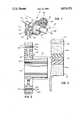
- FIG. 2is a vertical section, on an enlarged scale, taken general line 2--2 of FIG. 1, through one of the gears of the invention.
- FIG. 3is an enlarged fragmented section through the area of the gear incorporating the compliant laminate.
- gear system 10which may be part of a parallel shaft gear box, including two parallel power paths 12.
- gear systemis designed to divide power and reduce loads on the bearings of the system. With such arrangements, it is difficult to maintain tolerances and/or precise gear meshing in order to prevent an undue share of the load from being transmitted by one path.
- an inputis directed to a shaft 16 which carries a drive gear 18.
- a shaft 20provides an output, as indicated by arrow 22.
- a driven gear 24is coupled to output shaft 20.
- a pair of power transmitting gears 26, on parallel power paths 12,are in mesh with drive gear 18.
- Each power transmitting gear 26includes an integral, smaller pinion gear 28 conjointly rotatable therewith and in mesh with driven gear 24. Therefore, it can be seen that the power is divided down paths 12 through gears 26, 28 which establish a driving relationship between drive gear 18 and driven gear 24.
- the inventionis illustrated as incorporated in power transmitting gears 26 as described above in relation to FIG. 1. However, it should be understood that the compliant gear concept of this invention is equally applicable for a wide range of gear systems, including planetary gear systems or other suitable applications.
- each compliant gear 26includes a hub portion 30, a web portion 32, and a rim portion 34.
- Rim portion 34forms a ring gear including gear teeth 36 for the compliant gear.
- compliant gear 26is shown herein as being formed integrally with pinion gear 28.
- hub portion 30actually comprises the hub for the compliant gear as well as the hub for the respective pinion gear.
- hub portionshould be understood within the inventive concept and claims hereof as to include any type of gear which might have the hub portion, along with web portion 32, as a singular structural component or any other supporting structure.
- the inventioncontemplates a compliant laminate, generally designated 36, between hub or web portion 32 and rim or ring gear portion 34.
- the laminateincludes a rigid laminar shim 38 sandwiched between a pair of elastomer layers 40a and 40b.
- elastomer layers 40a and 40bare contemplated.
- the laminar shim and the elastomer layerseach is of generally uniform thickness and extends generally parallel to the axis of rotation 42 of the gear.
- the elastomer layers and shimsmay be generally parallel to each other but not to the axis of the gear.
- cone-shaped (frusto-conical) elastomers and shimsare contemplated.
- elastomer layers 40a, 40bgenerally are of greater thickness than laminar shim 38.
- compliant gear 26An exemplary dimensional arrangement of compliant gear 26 would be to provide the gear with an outside diameter of approximately four inches, with elastomer layers 40a, 40b having a thickness on the order of 0.05 inch and laminar shim 38 having a thickness on the order of 0.02 inch.
- the laminar shimmay be fabricated of metal or like rigid material, and elastomer layers 40a, 40b may be fabricated of rubber or like material.
- Elastomer layer 40ais bonded to hub or web portion 32 as well as to the inside annular surface of laminar shim 38.
- Elastomer layer 40bis bonded to rim or ring gear portion 34 as well as to the outside annular surface of laminar shim 38.
- the inter-laminar shim 38provides very high radial stiffness, in the range of a journal bearing, which heretofore has not been available with simple elastomer inserts in compliant gears.
- the stiffnessallows for the use of an independent elastomeric construction without additional metallic supports and results in a gear element with desirable running center displacement.
- compliant laminate 36can best be understood by envisioning a design wherein a given sheer or torsional stiffness is desired. This stiffness is a function of the thickness of any elastomer material disposed between hub portion 32 and rim portion 34 of the gear. The durometer of the elastomer material could be changed to increase the radial stiffness, but this, in turn, would change the sheer or torsional stiffness By using laminar shim 38, a considerably greater radial stiffness is provided without changing the sheer or torsional stiffness of the gear element.
- the layered structure of compliant laminate 36provides greater frequency dispersal of sound wave lengths as the waves must travel through the different layers of different material.
Landscapes
- Engineering & Computer Science (AREA)
- General Engineering & Computer Science (AREA)
- Mechanical Engineering (AREA)
- Physics & Mathematics (AREA)
- Acoustics & Sound (AREA)
- Aviation & Aerospace Engineering (AREA)
- Gears, Cams (AREA)
Abstract
Description
This invention generally relates to gearing and particularly to an improved compliant, shock absorbing and noise dissipating gear.
Compliant gears have been used in various applications for shock absorbing purposes, for accommodating tolerance problems between meshing gear teeth and for reducing sound-generating vibrations caused by the meshing gear teeth.
In designing such a gear or gear systems, a yieldable material has been employed between a hub portion of the gear and a toothed ring portion of the gear. In essence, the yieldable material, such as rubber or other elastomer material, permits the gear teeth to move radially and torsionally relative to the rigid gear hub. Gear meshing problems are particularly prevalent in gear systems which employ parallel gear paths which require precise angular positioning of the gear teeth of a pair of gears on opposite sides of an output gear, for instance.
In designing compliant gears, it most often is desirable to have a fixed torsional stiffness for proper gear teeth meshing and power transmission. In other words, the gear teeth cannot twist beyond certain parameters based upon timing with other gears. On the other hand, the design must provide for radial stiffness to maintain center-line distances between the meshing gears as well as maintaining proper meshing geometry. The interrelationship between these parameters have constantly caused problems in gear design.
For instance, compliant gears conventionally have incorporated a single layer of elastomer material between a hub portion and a rim or ring gear portion of the gear. Elastomeric material, such as rubber, is an "incompressible fluid" and the torsional or radial stiffness thereof normally is a function of the thickness of the elastomer layer. Therefore, if a given torsional or sheer stiffness is desired, any change in the thickness of the elastomer layer for changing the radial stiffness would, of necessity, also change the torsional stiffness. Any change in the durometer of the elastomer layer also would change the torsional stiffness. Consequently, it is readily apparent that the simple use of an elastomer layer to provide a compliant gear has definite limitations This invention has solved many of these problems by providing a compliant laminate between the hub portion and the rim portion of the gear, the laminate including a rigid laminar shim sandwiched between a pair of elastomer layers. Such a novel construction provides considerably more radial stiffness but does not change the desired torsional stiffness in any given thickness of laminate between the hub and rim portions of the gear.
Much consideration also has been given in the past to reducing the sound-generating vibrations which accompany the meshing of gear teeth. Although the reduction of noise is desirable in any gear system which is intended to operate in the vicinity of human or animal hearing, the problem becomes particularly critical in designing apparatus, such as torpedos or other marine vessels, where noiseless and smooth operation is essential. Sound-generating vibrations are caused by the point where gears engage when the driving gear imposes a torque on the driven gear through contact between the mutually extending gear teeth. As successive gear teeth engage and disengage, it is apparent that a series of periodic compressive impulses are transmitted radially to the gear hub. These impulses are transmitted as vibrations from the hub to the gear shaft, from the shaft to the bearings, and to the supporting structure, where they emanate as sound from the larger gear casing surfaces. The sound is transmitted by waves through these components of the apparatus. Again, internal elastomer layers or structures have been employed for reducing the noise and undesirable vibrations caused by the meshing of the teeth in a pair of gears.
With the invention, by providing a laminate with an interior rigid laminar shim, the sound waves are broken to a considerably greater extent than prior compliant gears described above.
An object, therefore, of the invention is to provide a gear system with a new and improved compliant gear.
In the exemplary embodiment of the invention, a compliant gear includes a hub portion and a power transmitting rim portion. The rim portion comprises an outer toothed ring gear. A compliant laminate is disposed between the hub and rim portions. The laminate includes a rigid laminar shim sandwiched between a pair of elastomer layers. Of course, there may be multiple layers of elastomers and shims.
As shown herein, the laminar shim and the elastomer layers are of generally uniform thickness and extend generally parallel to the axis of rotation of the gear. However, the parallel elastomer layers and shims could be cone-shaped, or the like, and not be parallel to the gear axis itself. Generally, the elastomer layers are of greater thickness than the laminar shim. The elastomer layers are bonded to the laminar shim as well as to the respective hub portion or ring gear portion. The laminar shim may be fabricated of metal or like material, and the elastomer layers may be fabricated of rubber or like material.
The invention is illustrated herein in a gear system which includes parallel power paths, with one of the compliant gears coupled in each path and in mesh directly or indirectly with a common driven gear. Of course, it should be understood that the compliant gear of this invention has a wide range of applications, including planetary gear systems or the like. The internal compliant laminate not only provides shock absorbing and noise dissipating characteristics, but the compliant gear has very high radial stiffness without additional metallic supports and results in a gear component with desirable running center displacement.
Other objects, features and advantages of the invention will be apparent from the following detailed description taken in connection with the accompanying drawings.
The features of this invention which are believed to be novel are set forth with particularity in the appended claims. The invention, together with its objects and the advantages thereof, may be best understood by reference to the following description taken in conjunction with the accompanying drawings, in which like reference numerals identify like elements in the figures and in which:
FIG. 1 is a fragmented perspective view of a gear system employing a pair of compliant gears according to the invention;
FIG. 2 is a vertical section, on an enlarged scale, takengeneral line 2--2 of FIG. 1, through one of the gears of the invention; and
FIG. 3 is an enlarged fragmented section through the area of the gear incorporating the compliant laminate.
Referring to the drawings in greater detail, and first to FIG. 1, the invention is illustrated in a gear system, generally designated 10, which may be part of a parallel shaft gear box, including twoparallel power paths 12. Such a gearing system is designed to divide power and reduce loads on the bearings of the system. With such arrangements, it is difficult to maintain tolerances and/or precise gear meshing in order to prevent an undue share of the load from being transmitted by one path.
More particularly, an input, indicated byarrow 14, is directed to ashaft 16 which carries adrive gear 18. Ashaft 20 provides an output, as indicated byarrow 22. A drivengear 24 is coupled tooutput shaft 20. A pair of power transmittinggears 26, onparallel power paths 12, are in mesh withdrive gear 18. Each power transmittinggear 26 includes an integral,smaller pinion gear 28 conjointly rotatable therewith and in mesh with drivengear 24. Therefore, it can be seen that the power is divided downpaths 12 throughgears drive gear 18 and drivengear 24.
The invention is illustrated as incorporated in power transmittinggears 26 as described above in relation to FIG. 1. However, it should be understood that the compliant gear concept of this invention is equally applicable for a wide range of gear systems, including planetary gear systems or other suitable applications.
More particularly, referring to FIGS. 2 and 3, eachcompliant gear 26 includes ahub portion 30, aweb portion 32, and arim portion 34.Rim portion 34 forms a ring gear includinggear teeth 36 for the compliant gear.
It should be understood thatcompliant gear 26 is shown herein as being formed integrally withpinion gear 28. In other words,hub portion 30 actually comprises the hub for the compliant gear as well as the hub for the respective pinion gear. The term "hub portion" should be understood within the inventive concept and claims hereof as to include any type of gear which might have the hub portion, along withweb portion 32, as a singular structural component or any other supporting structure.
The invention contemplates a compliant laminate, generally designated 36, between hub orweb portion 32 and rim orring gear portion 34. The laminate includes a rigidlaminar shim 38 sandwiched between a pair ofelastomer layers rotation 42 of the gear. However, the elastomer layers and shims may be generally parallel to each other but not to the axis of the gear. For instance, cone-shaped (frusto-conical) elastomers and shims are contemplated. As illustrated,elastomer layers laminar shim 38.
An exemplary dimensional arrangement ofcompliant gear 26 would be to provide the gear with an outside diameter of approximately four inches, withelastomer layers laminar shim 38 having a thickness on the order of 0.02 inch.
The laminar shim may be fabricated of metal or like rigid material, andelastomer layers Elastomer layer 40a is bonded to hub orweb portion 32 as well as to the inside annular surface oflaminar shim 38.Elastomer layer 40b is bonded to rim orring gear portion 34 as well as to the outside annular surface oflaminar shim 38.
Theinter-laminar shim 38 provides very high radial stiffness, in the range of a journal bearing, which heretofore has not been available with simple elastomer inserts in compliant gears. The stiffness allows for the use of an independent elastomeric construction without additional metallic supports and results in a gear element with desirable running center displacement.
The uniqueness ofcompliant laminate 36 can best be understood by envisioning a design wherein a given sheer or torsional stiffness is desired. This stiffness is a function of the thickness of any elastomer material disposed betweenhub portion 32 andrim portion 34 of the gear. The durometer of the elastomer material could be changed to increase the radial stiffness, but this, in turn, would change the sheer or torsional stiffness By usinglaminar shim 38, a considerably greater radial stiffness is provided without changing the sheer or torsional stiffness of the gear element.
Furthermore, in those applications where noise dissipation is a premium, the layered structure ofcompliant laminate 36 provides greater frequency dispersal of sound wave lengths as the waves must travel through the different layers of different material.
It will be understood that the invention may be embodied in other specific forms without departing from the spirit or central characteristics thereof. The present examples and embodiments, therefore, are to be considered in all respects as illustrative and not restrictive, and the invention is not to be limited to the details given herein.
Claims (19)
1. In a gear system, a gear comprising:
a gear hub portion;
a gear power transmitting rim portion; and
a compliant laminate between the gear hub and gear rim portions, the laminate including radial stiffness means for the gear in the form of a rigid laminar shim sandwiched between a pair of elastomer layers.
2. The gear system of claim 1 wherein said elastomer layers generally are of greater thickness than the laminar shim.
3. The gear system of claim 1 wherein said hub portion includes a gear web.
4. The gear system of claim 1 wherein said rim portion comprises a ring gear.
5. The gear system of claim 1 wherein said laminar shim is of generally uniform thickness and extends generally parallel to the axis of rotation of the gear.
6. The gear system of claim 5 wherein each of said elastomer layers is of generally uniform thickness and extends generally parallel to the axis of rotation of the gear.
7. The gear system of claim 6 wherein at least one of said elastomer layers is of greater thickness than the laminar shim.
8. The gear system of claim 1 wherein said elastomer layers are fabricated of rubber or like material.
9. The gear system of claim 1 wherein said laminar shim is fabricated of metal or like material.
10. The gear system of claim 1 wherein said elastomer layers are bonded to the laminar shim and to the respective hub portion or rim portion.
11. The gear system of claim 1 wherein the system includes parallel power paths, with one of said gears in each path and in mesh with a common driven gear.
12. A compliant gear, comprising:
an inner gear hub portion;
an outer ring gear portion; and
a compliant laminate between the gear hub portion and the ring gear portion, the laminate including radial stiffness means for the gear in the form of a rigid laminar shim of generally uniform thickness sandwiched between a pair of elastomer layers of generally uniform thickness, the elastomer layers being bonded to the laminar shim and to the respective hub portion or ring gear portion.
13. The compliant gear of claim 12 wherein said elastomer layers generally are of greater thickness than the laminar shim.
14. The compliant gear of claim 12 wherein said hub portion includes a gear web.
15. The compliant gear of claim 12 wherein said laminar shim extends generally parallel to the axis of rotation of the gear.
16. The compliant gear of claim 15 wherein said elastomer layers extend generally parallel to the axis of rotation of the gear.
17. The compliant gear of claim 16 wherein at least one of said elastomer layers is of greater thickness than the laminar shim.
18. The compliant gear of claim 12 wherein said elastomer layers are fabricated of rubber or like material.
19. The compliant gear of claim 12 wherein said laminar shim is fabricated of metal or like material.
Priority Applications (1)
| Application Number | Priority Date | Filing Date | Title |
|---|---|---|---|
| US06/812,255US4674351A (en) | 1985-12-23 | 1985-12-23 | Compliant gear |
Applications Claiming Priority (1)
| Application Number | Priority Date | Filing Date | Title |
|---|---|---|---|
| US06/812,255US4674351A (en) | 1985-12-23 | 1985-12-23 | Compliant gear |
Publications (1)
| Publication Number | Publication Date |
|---|---|
| US4674351Atrue US4674351A (en) | 1987-06-23 |
Family
ID=25209019
Family Applications (1)
| Application Number | Title | Priority Date | Filing Date |
|---|---|---|---|
| US06/812,255Expired - LifetimeUS4674351A (en) | 1985-12-23 | 1985-12-23 | Compliant gear |
Country Status (1)
| Country | Link |
|---|---|
| US (1) | US4674351A (en) |
Cited By (72)
| Publication number | Priority date | Publication date | Assignee | Title |
|---|---|---|---|---|
| US4796488A (en)* | 1986-03-18 | 1989-01-10 | Man Nutzfahrzeuge Gmbh | Differential whose a ring gear is mounted in sound damping manner on its carrier |
| US4831897A (en)* | 1987-10-05 | 1989-05-23 | Sundstrand Corporation | Torsionally compliant gear for use in multiple load path transmissions |
| US4843912A (en)* | 1988-06-24 | 1989-07-04 | Sundstrand Corp. | Variable stiffness support ring |
| US4912998A (en)* | 1986-04-11 | 1990-04-03 | Honda Giken Kogyo Kabushiki Kaisha | Gear arrangement |
| EP0457711A1 (en)* | 1990-05-16 | 1991-11-21 | United Technologies Corporation | Split torque helicopter main rotor drive including an elastomeric torsional vibration damper |
| US5113713A (en)* | 1991-02-11 | 1992-05-19 | United Technologies Corporation | Elastomeric load sharing device |
| US5214975A (en)* | 1990-11-20 | 1993-06-01 | New Venture Gear, Inc. | Transmission vibration damping |
| US5301073A (en)* | 1991-05-29 | 1994-04-05 | Hitachi, Ltd. | Take-up pulley with torque-limiting mechanism for magnetic recording and reproducing apparatus |
| US5307705A (en)* | 1993-02-09 | 1994-05-03 | Fenelon Paul J | Stress dissipation gear and method of making same |
| US5372215A (en)* | 1991-01-16 | 1994-12-13 | Yamaha Hatsudoki Kabushiki Kaisha | Split engine for a snowmobile having an angular motion accommodating connection between the two engine output shafts |
| US5452622A (en)* | 1993-02-09 | 1995-09-26 | Magi, L.P. | Stress dissipation gear |
| EP0761271A1 (en)* | 1995-08-08 | 1997-03-12 | NIKKO Co., Ltd. | Improved counter gear for a radio controlled toy car |
| US5653144A (en) | 1993-02-09 | 1997-08-05 | Fenelon; Paul J. | Stress dissipation apparatus |
| US5878843A (en)* | 1997-09-24 | 1999-03-09 | Hayes Lemmerz International, Inc. | Laminated brake rotor |
| US5911788A (en)* | 1998-02-20 | 1999-06-15 | Sundstrand Corporation | Compliant gear |
| US5956998A (en) | 1996-06-06 | 1999-09-28 | Fenelon; Paul J. | Stress reduction gear and apparatus using same |
| WO2001053044A1 (en)* | 2000-01-18 | 2001-07-26 | Buck David A | Load equalizing power tong gear train |
| US20020078777A1 (en)* | 2000-12-27 | 2002-06-27 | Witucki David E. | Gear assembly |
| US6428443B1 (en) | 2001-01-29 | 2002-08-06 | Delphi Oracle Corp. | Split torque epicyclic gearing |
| EP1321696A1 (en)* | 2001-12-20 | 2003-06-25 | Renault s.a.s. | Balancing system for internal combustion engine |
| US20040084865A1 (en)* | 2002-01-11 | 2004-05-06 | Koyo Seiko Co.,Ltd. | Gear, reduction gear combination and electric power steering apparatus |
| US20040261273A1 (en)* | 2003-06-24 | 2004-12-30 | Griep David B. | Drive mechanism and power tool |
| US20050085331A1 (en)* | 2003-10-21 | 2005-04-21 | Prucher Stephen L. | Over-molded net-shaped gear and manufacturing method |
| US20080041177A1 (en)* | 2006-07-27 | 2008-02-21 | Brosowske Thomas A | Compliant gear assembly and work machine using same |
| WO2008062192A1 (en)* | 2006-11-22 | 2008-05-29 | Zeroshift Limited | Transmission system |
| US20080243265A1 (en)* | 2007-02-06 | 2008-10-02 | Deka Products Limited Partnership | Method and apparatus for control of a prosthetic |
| US20080236933A1 (en)* | 2007-04-02 | 2008-10-02 | Jtekt Corporation | Vehicle steering system |
| US20080288088A1 (en)* | 2007-02-06 | 2008-11-20 | Deka Products Limited Partnership | Arm prosthetic device |
| US20090217779A1 (en)* | 2006-07-27 | 2009-09-03 | Caterpillar, Inc. | Compliant gear assembly, engine and gear train operating method |
| US20090255357A1 (en)* | 2005-05-18 | 2009-10-15 | Zeroshift Limited | Transmission layout |
| US20090271000A1 (en)* | 2007-02-06 | 2009-10-29 | Deka Products Limited Partnership | Dynamic support apparatus |
| US20100005914A1 (en)* | 2008-07-10 | 2010-01-14 | Delphi Technologies Inc. | Power steering device including a compliant gear |
| FR2938031A1 (en)* | 2008-11-04 | 2010-05-07 | Renault Sas | ABSORPTION OF TORQUE OSCILLATIONS FOR DEVICE FOR COUPLING A GEARBOX SHAFT WITH AN IDLE PINION MOUNTED ON THIS TREE |
| US20100268351A1 (en)* | 2007-02-06 | 2010-10-21 | Deka Products Limited Partnership | System, method and apparatus for control of a prosthetic device |
| US20100274365A1 (en)* | 2007-02-06 | 2010-10-28 | Deka Products Limited Partnership | Arm prosthetic device |
| US20100326224A1 (en)* | 2008-03-21 | 2010-12-30 | Toyota Jidosha Kabushiki Kaisha | Gear device and power transmission apparatus |
| US20110140172A1 (en)* | 2009-12-10 | 2011-06-16 | Transphorm Inc. | Reverse side engineered iii-nitride devices |
| US20110250070A1 (en)* | 2008-12-10 | 2011-10-13 | Vestas Wind Systems A/S | Composite gear part for a gear arrangement and a method of forming a composite gear part |
| US8453340B2 (en) | 2007-02-06 | 2013-06-04 | Deka Products Limited Partnership | System, method and apparatus for orientation control |
| WO2014210462A1 (en)* | 2013-06-28 | 2014-12-31 | General Electric Company | Lightweight gear assembly for epicyclic gearbox |
| US8956421B2 (en) | 2007-02-06 | 2015-02-17 | Deka Products Limited Partnership | Dynamic support apparatus and system |
| US8979943B2 (en) | 2007-02-06 | 2015-03-17 | Deka Products Limited Partnership | Arm prosthetic device |
| DE102014225990A1 (en) | 2014-02-13 | 2015-08-13 | Metaldyne International Deutschland Gmbh | gear |
| US20150226303A1 (en)* | 2014-02-13 | 2015-08-13 | Miba Sinter Austria Gmbh | Gear |
| US9114030B2 (en) | 2007-02-06 | 2015-08-25 | Deka Products Limited Partnership | System for control of a prosthetic device |
| US9296157B1 (en)* | 2011-07-08 | 2016-03-29 | The United States Of America As Represented By The Administrator Of National Aeronautics And Space Administration | Hybrid gear |
| US9605744B2 (en) | 2012-04-24 | 2017-03-28 | Gkn Sinter Metals, Llc | Dampening assembly and related method of making same |
| EP3147538A1 (en) | 2015-09-23 | 2017-03-29 | Inovacor Ab | Compound planet gear arrangement and drive train arrangement |
| US20170227116A1 (en)* | 2016-02-05 | 2017-08-10 | Ford Global Technologies, Llc | Gear assembly |
| EP2706268A3 (en)* | 2012-09-07 | 2017-09-06 | Bayerische Motoren Werke Aktiengesellschaft | Gear transmission |
| US20170261087A1 (en)* | 2016-03-11 | 2017-09-14 | Deere & Company | Composite gears and methods of manufacturing such gears |
| US9844447B2 (en) | 2010-04-09 | 2017-12-19 | Deka Products Limited Partnership | System and apparatus for robotic device and methods of using thereof |
| US20180016938A1 (en)* | 2016-07-12 | 2018-01-18 | Rolls-Royce Plc | Geared gas turbine engine and a gearbox |
| US9909642B2 (en)* | 2015-04-08 | 2018-03-06 | Vibracoustic Gmbh | Damper for a drive train |
| EP3379106A1 (en) | 2017-03-23 | 2018-09-26 | Cordrive Ab | Compound planet gear arrangement and gear wheel arrangement |
| EP3379108A1 (en) | 2017-03-23 | 2018-09-26 | Cordrive Ab | Compound planet gear arrangement and gear wheel arrangement |
| EP3379107A1 (en) | 2017-03-23 | 2018-09-26 | Cordrive Ab | Compound planet gear arrangement and gear wheel arrangement |
| EP3379109A1 (en) | 2017-03-23 | 2018-09-26 | Cordrive Ab | Compound planet gear arrangment and gear wheel arrangement |
| WO2018172479A2 (en) | 2017-03-23 | 2018-09-27 | Cordrive Ab | Compound planet gear arrangement and gear wheel arrangement |
| DE102017106699A1 (en)* | 2017-03-29 | 2018-10-04 | Schaeffler Technologies AG & Co. KG | Multiple gear and gear arrangement with the multiple gear |
| US10408134B2 (en)* | 2015-06-11 | 2019-09-10 | Rolls-Royce Plc | Gears, gear arrangements and gas turbine engines |
| AT521377B1 (en)* | 2018-11-28 | 2020-01-15 | Metaldyne Int Deutschland Gmbh | gear drive |
| DE102019134083A1 (en) | 2019-01-04 | 2020-07-09 | Miba Sinter Austria Gmbh | gear |
| AT522070B1 (en)* | 2019-03-13 | 2020-08-15 | Miba Sinter Austria Gmbh | gear |
| US11041559B2 (en) | 2018-04-13 | 2021-06-22 | 1-Up Design and Consulting, LLC | Device and method of gear noise reduction |
| US20210231206A1 (en)* | 2018-06-21 | 2021-07-29 | Showa Denko Materials Co., Ltd. | Resin gear |
| US11125301B1 (en) | 2020-03-31 | 2021-09-21 | Circular Wave Drive Partners Inc. | Circular wave drive |
| US11464655B2 (en) | 2007-02-06 | 2022-10-11 | Deka Products Limited Partnership | Arm prosthetic device |
| US11473663B1 (en) | 2018-02-23 | 2022-10-18 | United States Of America As Represented By The Administrator Of National Aeronautics And Space Administration | Continuous fiber composite power transfer structures |
| US11525502B2 (en) | 2019-06-13 | 2022-12-13 | Circular Wave Drive Partners Inc. | Circular wave drive |
| US11779476B2 (en) | 2007-02-06 | 2023-10-10 | Deka Products Limited Partnership | Arm prosthetic device |
| US12011375B2 (en) | 2007-02-06 | 2024-06-18 | Deka Products Limited Partnership | Arm prosthetic device |
Citations (19)
| Publication number | Priority date | Publication date | Assignee | Title |
|---|---|---|---|---|
| US1424203A (en)* | 1920-11-04 | 1922-08-01 | Katharina Keller | Gear wheel |
| US1928763A (en)* | 1931-02-12 | 1933-10-03 | Budd Wheel Co | Gear |
| US2187706A (en)* | 1936-01-25 | 1940-01-16 | Julien Maurice Franc Alexandre | Power transmitting coupling |
| US2307129A (en)* | 1940-04-05 | 1943-01-05 | Int Projector Corp | Shockproof gear |
| US2460630A (en)* | 1945-04-12 | 1949-02-01 | Thomas L Fawick | Multicushioned gear |
| US2702995A (en)* | 1953-12-31 | 1955-03-01 | Goodman Mfg Co | Shock absorbing gearing |
| US2753731A (en)* | 1953-01-15 | 1956-07-10 | Admiral Corp | Power transmission mechanism |
| US2939331A (en)* | 1959-03-25 | 1960-06-07 | Gen Electric | Quiet gear |
| US3020036A (en)* | 1958-02-21 | 1962-02-06 | Gelenkwellenbau Gmbh | Rubber spring |
| US3071850A (en)* | 1960-08-18 | 1963-01-08 | Fred L Haushalter | Method of making a composite assembly for use between concentric sections of a torsional shaft |
| US3076352A (en)* | 1958-10-13 | 1963-02-05 | Everett P Larsh | Gear members and method of producing same |
| US3167975A (en)* | 1962-05-12 | 1965-02-02 | Francois Durand | Device for transmitting motion to a gear |
| US3216267A (en)* | 1963-02-15 | 1965-11-09 | Dolza John | Rotary motion transmitting mechanism for internal combustion engines and the like |
| US3304795A (en)* | 1966-02-28 | 1967-02-21 | William S Rouverol | Nonlubricated formed gearing |
| US3667317A (en)* | 1970-08-26 | 1972-06-06 | Int Harvester Co | Balancer |
| US3757608A (en)* | 1970-11-21 | 1973-09-11 | Bhs Bayerische Berg | Solar and planetary gear system with load pressure compensation |
| US3943788A (en)* | 1973-08-22 | 1976-03-16 | Firma Zahnraderfabrik Renk Aktiengesellschaft | Planar gear train |
| US3952546A (en)* | 1974-08-23 | 1976-04-27 | Kawasaki Jukogyo Kabushiki Kaisha | Elastic coupling |
| US4178811A (en)* | 1977-06-15 | 1979-12-18 | Wallace Murray Corporation | Meta reinforced plastic damper hub |
- 1985
- 1985-12-23USUS06/812,255patent/US4674351A/ennot_activeExpired - Lifetime
Patent Citations (19)
| Publication number | Priority date | Publication date | Assignee | Title |
|---|---|---|---|---|
| US1424203A (en)* | 1920-11-04 | 1922-08-01 | Katharina Keller | Gear wheel |
| US1928763A (en)* | 1931-02-12 | 1933-10-03 | Budd Wheel Co | Gear |
| US2187706A (en)* | 1936-01-25 | 1940-01-16 | Julien Maurice Franc Alexandre | Power transmitting coupling |
| US2307129A (en)* | 1940-04-05 | 1943-01-05 | Int Projector Corp | Shockproof gear |
| US2460630A (en)* | 1945-04-12 | 1949-02-01 | Thomas L Fawick | Multicushioned gear |
| US2753731A (en)* | 1953-01-15 | 1956-07-10 | Admiral Corp | Power transmission mechanism |
| US2702995A (en)* | 1953-12-31 | 1955-03-01 | Goodman Mfg Co | Shock absorbing gearing |
| US3020036A (en)* | 1958-02-21 | 1962-02-06 | Gelenkwellenbau Gmbh | Rubber spring |
| US3076352A (en)* | 1958-10-13 | 1963-02-05 | Everett P Larsh | Gear members and method of producing same |
| US2939331A (en)* | 1959-03-25 | 1960-06-07 | Gen Electric | Quiet gear |
| US3071850A (en)* | 1960-08-18 | 1963-01-08 | Fred L Haushalter | Method of making a composite assembly for use between concentric sections of a torsional shaft |
| US3167975A (en)* | 1962-05-12 | 1965-02-02 | Francois Durand | Device for transmitting motion to a gear |
| US3216267A (en)* | 1963-02-15 | 1965-11-09 | Dolza John | Rotary motion transmitting mechanism for internal combustion engines and the like |
| US3304795A (en)* | 1966-02-28 | 1967-02-21 | William S Rouverol | Nonlubricated formed gearing |
| US3667317A (en)* | 1970-08-26 | 1972-06-06 | Int Harvester Co | Balancer |
| US3757608A (en)* | 1970-11-21 | 1973-09-11 | Bhs Bayerische Berg | Solar and planetary gear system with load pressure compensation |
| US3943788A (en)* | 1973-08-22 | 1976-03-16 | Firma Zahnraderfabrik Renk Aktiengesellschaft | Planar gear train |
| US3952546A (en)* | 1974-08-23 | 1976-04-27 | Kawasaki Jukogyo Kabushiki Kaisha | Elastic coupling |
| US4178811A (en)* | 1977-06-15 | 1979-12-18 | Wallace Murray Corporation | Meta reinforced plastic damper hub |
Cited By (112)
| Publication number | Priority date | Publication date | Assignee | Title |
|---|---|---|---|---|
| US4796488A (en)* | 1986-03-18 | 1989-01-10 | Man Nutzfahrzeuge Gmbh | Differential whose a ring gear is mounted in sound damping manner on its carrier |
| US4912998A (en)* | 1986-04-11 | 1990-04-03 | Honda Giken Kogyo Kabushiki Kaisha | Gear arrangement |
| US4831897A (en)* | 1987-10-05 | 1989-05-23 | Sundstrand Corporation | Torsionally compliant gear for use in multiple load path transmissions |
| US4843912A (en)* | 1988-06-24 | 1989-07-04 | Sundstrand Corp. | Variable stiffness support ring |
| EP0457711A1 (en)* | 1990-05-16 | 1991-11-21 | United Technologies Corporation | Split torque helicopter main rotor drive including an elastomeric torsional vibration damper |
| US5117704A (en)* | 1990-05-16 | 1992-06-02 | United Technologies, Corporation | Elastomeric torsional isolator |
| US5214975A (en)* | 1990-11-20 | 1993-06-01 | New Venture Gear, Inc. | Transmission vibration damping |
| US5372215A (en)* | 1991-01-16 | 1994-12-13 | Yamaha Hatsudoki Kabushiki Kaisha | Split engine for a snowmobile having an angular motion accommodating connection between the two engine output shafts |
| US5113713A (en)* | 1991-02-11 | 1992-05-19 | United Technologies Corporation | Elastomeric load sharing device |
| US5301073A (en)* | 1991-05-29 | 1994-04-05 | Hitachi, Ltd. | Take-up pulley with torque-limiting mechanism for magnetic recording and reproducing apparatus |
| US5307705A (en)* | 1993-02-09 | 1994-05-03 | Fenelon Paul J | Stress dissipation gear and method of making same |
| US5452622A (en)* | 1993-02-09 | 1995-09-26 | Magi, L.P. | Stress dissipation gear |
| US5653144A (en) | 1993-02-09 | 1997-08-05 | Fenelon; Paul J. | Stress dissipation apparatus |
| US5692410A (en) | 1993-02-09 | 1997-12-02 | Fenelon; Paul J. | Rotatable apparatus having a stress dissipation structure |
| US5943913A (en) | 1993-02-09 | 1999-08-31 | Fenelon; Paul J. | Rotatable apparatus having a stress dissipation structure |
| EP0761271A1 (en)* | 1995-08-08 | 1997-03-12 | NIKKO Co., Ltd. | Improved counter gear for a radio controlled toy car |
| US5791190A (en)* | 1995-08-08 | 1998-08-11 | Nikko Co., Ltd. | Counter gear in a transmission gear mechanism for a radio controlled toy car |
| US5956998A (en) | 1996-06-06 | 1999-09-28 | Fenelon; Paul J. | Stress reduction gear and apparatus using same |
| US5878843A (en)* | 1997-09-24 | 1999-03-09 | Hayes Lemmerz International, Inc. | Laminated brake rotor |
| US5911788A (en)* | 1998-02-20 | 1999-06-15 | Sundstrand Corporation | Compliant gear |
| WO2001053044A1 (en)* | 2000-01-18 | 2001-07-26 | Buck David A | Load equalizing power tong gear train |
| US20020078777A1 (en)* | 2000-12-27 | 2002-06-27 | Witucki David E. | Gear assembly |
| US6428443B1 (en) | 2001-01-29 | 2002-08-06 | Delphi Oracle Corp. | Split torque epicyclic gearing |
| EP1321696A1 (en)* | 2001-12-20 | 2003-06-25 | Renault s.a.s. | Balancing system for internal combustion engine |
| FR2834029A1 (en)* | 2001-12-20 | 2003-06-27 | Renault | BALANCING SYSTEM FOR A COMBUSTION ENGINE |
| US20040084865A1 (en)* | 2002-01-11 | 2004-05-06 | Koyo Seiko Co.,Ltd. | Gear, reduction gear combination and electric power steering apparatus |
| US6988582B2 (en)* | 2002-01-11 | 2006-01-24 | Koyo Seiko Co., Ltd. | Gear, reduction gear combination and electric power steering apparatus |
| US20040261273A1 (en)* | 2003-06-24 | 2004-12-30 | Griep David B. | Drive mechanism and power tool |
| US20050085331A1 (en)* | 2003-10-21 | 2005-04-21 | Prucher Stephen L. | Over-molded net-shaped gear and manufacturing method |
| US7117598B2 (en) | 2003-10-21 | 2006-10-10 | American Axle & Manufacturing, Inc. | Net-shaped gear and manufacturing method for forming net-shaped gear employing insert and preform |
| US8291784B2 (en) | 2005-05-18 | 2012-10-23 | Zeroshift Limited | Transmission layout |
| US20090255357A1 (en)* | 2005-05-18 | 2009-10-15 | Zeroshift Limited | Transmission layout |
| WO2008013599A3 (en)* | 2006-07-27 | 2008-03-20 | Caterpillar Inc | Compliant gear assembly and work machine using same |
| US20120266706A1 (en)* | 2006-07-27 | 2012-10-25 | Caterpillar, Inc. | Compliant Gear Assembly, Engine And Gear Train Operating Method |
| US20090217779A1 (en)* | 2006-07-27 | 2009-09-03 | Caterpillar, Inc. | Compliant gear assembly, engine and gear train operating method |
| US20080041177A1 (en)* | 2006-07-27 | 2008-02-21 | Brosowske Thomas A | Compliant gear assembly and work machine using same |
| US8225689B2 (en) | 2006-07-27 | 2012-07-24 | Caterpillar Inc. | Compliant gear assembly, engine and gear train operating method |
| US7658124B2 (en) | 2006-07-27 | 2010-02-09 | Caterpillar Inc. | Compliant gear assembly and work machine using same |
| US20100257969A1 (en)* | 2006-11-22 | 2010-10-14 | Zeroshift Limited | Transmission system |
| WO2008062192A1 (en)* | 2006-11-22 | 2008-05-29 | Zeroshift Limited | Transmission system |
| CN101535673B (en)* | 2006-11-22 | 2012-05-30 | 哲若希福有限公司 | Transmission system |
| US8821587B2 (en) | 2007-02-06 | 2014-09-02 | Deka Products Limited Partnership | Apparatus for control of a prosthetic |
| US9114028B2 (en) | 2007-02-06 | 2015-08-25 | Deka Products Limited Partnership | Arm prosthetic device |
| US11464655B2 (en) | 2007-02-06 | 2022-10-11 | Deka Products Limited Partnership | Arm prosthetic device |
| US20100268351A1 (en)* | 2007-02-06 | 2010-10-21 | Deka Products Limited Partnership | System, method and apparatus for control of a prosthetic device |
| US20100274365A1 (en)* | 2007-02-06 | 2010-10-28 | Deka Products Limited Partnership | Arm prosthetic device |
| US11779476B2 (en) | 2007-02-06 | 2023-10-10 | Deka Products Limited Partnership | Arm prosthetic device |
| US9114030B2 (en) | 2007-02-06 | 2015-08-25 | Deka Products Limited Partnership | System for control of a prosthetic device |
| US12011375B2 (en) | 2007-02-06 | 2024-06-18 | Deka Products Limited Partnership | Arm prosthetic device |
| US12186211B2 (en) | 2007-02-06 | 2025-01-07 | Deka Products Limited Partnership | Arm prosthetic device |
| US8979943B2 (en) | 2007-02-06 | 2015-03-17 | Deka Products Limited Partnership | Arm prosthetic device |
| US20090271000A1 (en)* | 2007-02-06 | 2009-10-29 | Deka Products Limited Partnership | Dynamic support apparatus |
| US20080288088A1 (en)* | 2007-02-06 | 2008-11-20 | Deka Products Limited Partnership | Arm prosthetic device |
| US8956421B2 (en) | 2007-02-06 | 2015-02-17 | Deka Products Limited Partnership | Dynamic support apparatus and system |
| US8449624B2 (en) | 2007-02-06 | 2013-05-28 | Deka Products Limited Partnership | Arm prosthetic device |
| US8453340B2 (en) | 2007-02-06 | 2013-06-04 | Deka Products Limited Partnership | System, method and apparatus for orientation control |
| US20080243265A1 (en)* | 2007-02-06 | 2008-10-02 | Deka Products Limited Partnership | Method and apparatus for control of a prosthetic |
| US8864845B2 (en) | 2007-02-06 | 2014-10-21 | DEKA Limited Partnership | System for control of a prosthetic device |
| US8870970B2 (en) | 2007-02-06 | 2014-10-28 | Deka Products Limited Partnership | Dynamic support apparatus |
| US20080236933A1 (en)* | 2007-04-02 | 2008-10-02 | Jtekt Corporation | Vehicle steering system |
| US20100326224A1 (en)* | 2008-03-21 | 2010-12-30 | Toyota Jidosha Kabushiki Kaisha | Gear device and power transmission apparatus |
| US20100005914A1 (en)* | 2008-07-10 | 2010-01-14 | Delphi Technologies Inc. | Power steering device including a compliant gear |
| US8069745B2 (en) | 2008-07-10 | 2011-12-06 | Nexteer (Beijing) Technology Co., Ltd. | Power steering device including a compliant gear |
| EP2184502A1 (en)* | 2008-11-04 | 2010-05-12 | Renault S.A.S. | Absorption of torque oscillations for a coupling device of a gearbox shaft with an idler gear installed on this shaft |
| FR2938031A1 (en)* | 2008-11-04 | 2010-05-07 | Renault Sas | ABSORPTION OF TORQUE OSCILLATIONS FOR DEVICE FOR COUPLING A GEARBOX SHAFT WITH AN IDLE PINION MOUNTED ON THIS TREE |
| US8978501B2 (en)* | 2008-12-10 | 2015-03-17 | Vestas Wind Systems A/S | Composite gear part for a gear arrangement and a method of forming a composite gear part |
| US20110250070A1 (en)* | 2008-12-10 | 2011-10-13 | Vestas Wind Systems A/S | Composite gear part for a gear arrangement and a method of forming a composite gear part |
| US20110140172A1 (en)* | 2009-12-10 | 2011-06-16 | Transphorm Inc. | Reverse side engineered iii-nitride devices |
| US11628072B2 (en) | 2010-04-09 | 2023-04-18 | Deka Products Limited Partnership | System and apparatus for robotic device and methods of using thereof |
| US9844447B2 (en) | 2010-04-09 | 2017-12-19 | Deka Products Limited Partnership | System and apparatus for robotic device and methods of using thereof |
| US12220328B2 (en) | 2010-04-09 | 2025-02-11 | Deka Products Limited Partnership | System and apparatus for robotic device and methods of using thereof |
| US9296157B1 (en)* | 2011-07-08 | 2016-03-29 | The United States Of America As Represented By The Administrator Of National Aeronautics And Space Administration | Hybrid gear |
| US9605744B2 (en) | 2012-04-24 | 2017-03-28 | Gkn Sinter Metals, Llc | Dampening assembly and related method of making same |
| EP2706268A3 (en)* | 2012-09-07 | 2017-09-06 | Bayerische Motoren Werke Aktiengesellschaft | Gear transmission |
| CN105518348A (en)* | 2013-06-28 | 2016-04-20 | 通用电气公司 | Lightweight gear assembly for epicyclic gearbox |
| WO2014210462A1 (en)* | 2013-06-28 | 2014-12-31 | General Electric Company | Lightweight gear assembly for epicyclic gearbox |
| US9856964B2 (en)* | 2014-02-13 | 2018-01-02 | Miba Sinter Austria Gmbh | Gear |
| DE102014225192A1 (en) | 2014-02-13 | 2015-08-13 | Miba Sinter Austria Gmbh | gear |
| DE102014225990A1 (en) | 2014-02-13 | 2015-08-13 | Metaldyne International Deutschland Gmbh | gear |
| US20150226303A1 (en)* | 2014-02-13 | 2015-08-13 | Miba Sinter Austria Gmbh | Gear |
| DE102014225990B4 (en) | 2014-02-13 | 2023-05-04 | Metaldyne International Deutschland Gmbh | gear |
| US9909642B2 (en)* | 2015-04-08 | 2018-03-06 | Vibracoustic Gmbh | Damper for a drive train |
| US10408134B2 (en)* | 2015-06-11 | 2019-09-10 | Rolls-Royce Plc | Gears, gear arrangements and gas turbine engines |
| EP3147538A1 (en) | 2015-09-23 | 2017-03-29 | Inovacor Ab | Compound planet gear arrangement and drive train arrangement |
| WO2017052461A1 (en) | 2015-09-23 | 2017-03-30 | Inovacor Ab | Compound planet gear arrangement and drive train arrangement |
| US10533636B2 (en) | 2015-09-23 | 2020-01-14 | Cascade Drives Ab | Compound planet gear arrangement and drive train arrangement |
| US10641381B2 (en)* | 2016-02-05 | 2020-05-05 | Ford Global Technologies, Llc | Gear assembly |
| US20170227116A1 (en)* | 2016-02-05 | 2017-08-10 | Ford Global Technologies, Llc | Gear assembly |
| US20170261087A1 (en)* | 2016-03-11 | 2017-09-14 | Deere & Company | Composite gears and methods of manufacturing such gears |
| US11248692B2 (en)* | 2016-03-11 | 2022-02-15 | Deere & Company | Composite gears and methods of manufacturing such gears |
| US10458274B2 (en)* | 2016-07-12 | 2019-10-29 | Rolls-Royce Plc | Geared gas turbine engine and a gearbox |
| US20180016938A1 (en)* | 2016-07-12 | 2018-01-18 | Rolls-Royce Plc | Geared gas turbine engine and a gearbox |
| WO2018172479A2 (en) | 2017-03-23 | 2018-09-27 | Cordrive Ab | Compound planet gear arrangement and gear wheel arrangement |
| EP3379109A1 (en) | 2017-03-23 | 2018-09-26 | Cordrive Ab | Compound planet gear arrangment and gear wheel arrangement |
| EP3379107A1 (en) | 2017-03-23 | 2018-09-26 | Cordrive Ab | Compound planet gear arrangement and gear wheel arrangement |
| US11746876B2 (en) | 2017-03-23 | 2023-09-05 | Cascade Drives Ab | Compound planet gear arrangement and gear wheel arrangement |
| EP3379108A1 (en) | 2017-03-23 | 2018-09-26 | Cordrive Ab | Compound planet gear arrangement and gear wheel arrangement |
| EP3379106A1 (en) | 2017-03-23 | 2018-09-26 | Cordrive Ab | Compound planet gear arrangement and gear wheel arrangement |
| DE102017106699A1 (en)* | 2017-03-29 | 2018-10-04 | Schaeffler Technologies AG & Co. KG | Multiple gear and gear arrangement with the multiple gear |
| US11473663B1 (en) | 2018-02-23 | 2022-10-18 | United States Of America As Represented By The Administrator Of National Aeronautics And Space Administration | Continuous fiber composite power transfer structures |
| US11041559B2 (en) | 2018-04-13 | 2021-06-22 | 1-Up Design and Consulting, LLC | Device and method of gear noise reduction |
| US20210231206A1 (en)* | 2018-06-21 | 2021-07-29 | Showa Denko Materials Co., Ltd. | Resin gear |
| US11549576B2 (en)* | 2018-06-21 | 2023-01-10 | Showa Denko Materials Co., Ltd. | Resin gear |
| AT521377A4 (en)* | 2018-11-28 | 2020-01-15 | Metaldyne Int Deutschland Gmbh | gear drive |
| AT521377B1 (en)* | 2018-11-28 | 2020-01-15 | Metaldyne Int Deutschland Gmbh | gear drive |
| AT521959A4 (en)* | 2019-01-04 | 2020-07-15 | Miba Sinter Austria Gmbh | gear |
| AT521959B1 (en)* | 2019-01-04 | 2020-07-15 | Miba Sinter Austria Gmbh | gear |
| DE102019134083A1 (en) | 2019-01-04 | 2020-07-09 | Miba Sinter Austria Gmbh | gear |
| AT522070B1 (en)* | 2019-03-13 | 2020-08-15 | Miba Sinter Austria Gmbh | gear |
| AT522070A4 (en)* | 2019-03-13 | 2020-08-15 | Miba Sinter Austria Gmbh | gear |
| US11525502B2 (en) | 2019-06-13 | 2022-12-13 | Circular Wave Drive Partners Inc. | Circular wave drive |
| US11125301B1 (en) | 2020-03-31 | 2021-09-21 | Circular Wave Drive Partners Inc. | Circular wave drive |
Similar Documents
| Publication | Publication Date | Title |
|---|---|---|
| US4674351A (en) | Compliant gear | |
| EP2759743B1 (en) | Speed reducer | |
| US4898065A (en) | Planetary reduction gear | |
| CN100491767C (en) | Harmonic gearing | |
| EP0457711B1 (en) | Split torque helicopter main rotor drive including an elastomeric torsional vibration damper | |
| US11572942B2 (en) | Harmonic speed reducer | |
| CN107044535A (en) | Epicyclic gearing | |
| KR101015004B1 (en) | Planetary gear drive | |
| US3307419A (en) | Quiet gear | |
| CN110228059B (en) | Joint shaft structure of robot and robot | |
| JP2015113889A (en) | Gear device | |
| JP6554578B2 (en) | Cyclo gear | |
| JP2007016838A (en) | Top hat wave gear device | |
| KR20210101984A (en) | Plate harmonic reducer | |
| US5020923A (en) | Transmission/gearbox vibration damping system | |
| JP2006349091A (en) | Harmonic drive device, transmission ratio variable device, and vehicle steering device | |
| US11359699B2 (en) | Speed reducer | |
| JP2023140752A (en) | Rotating mechanisms and robots | |
| JP4468522B2 (en) | Gear transmission case | |
| US20250035200A1 (en) | Gear Structure | |
| CN101876362B (en) | Structure for inhibiting slapping noise of gears | |
| JPH01266363A (en) | Gear power transmission device | |
| CN222668822U (en) | Harmonic reducer device and wave generating unit thereof | |
| EP3869056A1 (en) | Yielding shaft coupling with an intermediate member of elastic material | |
| CN222782953U (en) | Harmonic reducer |
Legal Events
| Date | Code | Title | Description |
|---|---|---|---|
| AS | Assignment | Owner name:SUNDSTRAND CORPORATION, A CORP. OF DE. Free format text:ASSIGNMENT OF ASSIGNORS INTEREST.;ASSIGNOR:BYRD, WILLIAM A.;REEL/FRAME:004506/0280 Effective date:19851217 | |
| STCF | Information on status: patent grant | Free format text:PATENTED CASE | |
| FEPP | Fee payment procedure | Free format text:PAYOR NUMBER ASSIGNED (ORIGINAL EVENT CODE: ASPN); ENTITY STATUS OF PATENT OWNER: LARGE ENTITY | |
| FPAY | Fee payment | Year of fee payment:4 | |
| FPAY | Fee payment | Year of fee payment:8 | |
| FPAY | Fee payment | Year of fee payment:12 | |
| FEPP | Fee payment procedure | Free format text:PAYER NUMBER DE-ASSIGNED (ORIGINAL EVENT CODE: RMPN); ENTITY STATUS OF PATENT OWNER: LARGE ENTITY Free format text:PAYOR NUMBER ASSIGNED (ORIGINAL EVENT CODE: ASPN); ENTITY STATUS OF PATENT OWNER: LARGE ENTITY |