US4673976A - Cable television system data verification apparatus - Google Patents
Cable television system data verification apparatusDownload PDFInfo
- Publication number
- US4673976A US4673976AUS06/615,778US61577884AUS4673976AUS 4673976 AUS4673976 AUS 4673976AUS 61577884 AUS61577884 AUS 61577884AUS 4673976 AUS4673976 AUS 4673976A
- Authority
- US
- United States
- Prior art keywords
- data
- subscriber
- transmission line
- electronic device
- echo back
- Prior art date
- Legal status (The legal status is an assumption and is not a legal conclusion. Google has not performed a legal analysis and makes no representation as to the accuracy of the status listed.)
- Expired - Lifetime
Links
Images


Classifications
- H—ELECTRICITY
- H04—ELECTRIC COMMUNICATION TECHNIQUE
- H04N—PICTORIAL COMMUNICATION, e.g. TELEVISION
- H04N7/00—Television systems
- H04N7/16—Analogue secrecy systems; Analogue subscription systems
- H04N7/173—Analogue secrecy systems; Analogue subscription systems with two-way working, e.g. subscriber sending a programme selection signal
- H04N7/17309—Transmission or handling of upstream communications
- H—ELECTRICITY
- H04—ELECTRIC COMMUNICATION TECHNIQUE
- H04L—TRANSMISSION OF DIGITAL INFORMATION, e.g. TELEGRAPHIC COMMUNICATION
- H04L1/00—Arrangements for detecting or preventing errors in the information received
- H04L1/12—Arrangements for detecting or preventing errors in the information received by using return channel
- H04L1/14—Arrangements for detecting or preventing errors in the information received by using return channel in which the signals are sent back to the transmitter to be checked ; echo systems
Definitions
- This inventionrelates to cable television (“CATV”) systems, and more particularly to apparatus for verifying that data transmitted in a CATV system for such purposes as system control is correctly transmitted and received.
- CATVcable television
- a head endtransmits CATV signals along a trunk cable.
- the trunk cableConnected to the trunk cable are feeder cables, to which in turn are connected drop cables.
- the drop cablesconnect the feeder lines to converter/tuner units located in subscribers' houses.
- a subscriberdesires to tune to and view a particular TV channel, he or she keys the requested channel into the converter/tuner. If the subscriber has subscribed with the CATV service company for the requested channel, the converter/tuner tunes the selected channel from among a plurality of channels available on the drop cable and converts the selected channel to a form and frequency suitable for viewing on the subscriber's television set. If the subscriber has not subscribed for the requested channel, the converter/tuner will not tune to or enable the viewing of the requested channel.
- the subscribermay modify the converter/tuner to allow the subscriber to view CATV channels for which the subscriber has not subscribed, thus resulting in a loss of revenue to the CATV service company.
- the subscribermay remove the expensive converter/tuner. Again, the CATV service company incurs a loss.
- Each external control unitmay include a plurality of converter/tuners, each connected to a respective one of a plurality of subscribers' houses by a respective one of a plurality of drop cables.
- a subscriber processing unitwhich connects to the subscriber's drop cable and to the subscriber's television set. The subscriber may key into the subscriber processing unit a TV channel request.
- the subscriber processing unittransmits the request to the external control unit via the drop cable in the form of a modulated data signal. If the subscriber is authorized to view the requested channel (i.e., if the subscriber has subscribed and paid for the channel), the converter/tuner located in the external control unit which is associated with the subscriber tunes to the requested channel and transmits the channel to the subscriber via the drop cable.
- CATV systemsolves the problems of modification and removal of converter/tuners, problems may occur in communicating channel requests from the subscriber processing unit to the external control unit. For example, noise or poor connections along the communication path between the external control unit and the subscriber processing unit may degrade or modify the data signal containing the subscriber's TV channel request. As a result, a different channel request from the actual channel request might be received by the external control unit, or no channel request might be received. In either case, the subscriber does not receive the TV channel which he keyed into his subscriber processing unit.
- the present inventionhas been made in consideration of the above situation, and has for its object to provide data verification apparatus for use in confirming that data transmitted in a CATV system is correctly transmitted and received.
- data transmitted by a subscriber processing unitis stored by the subscriber processing unit as well as being transmitted to the associated external control unit via the associated drop cable.
- the external control unitreceives and stores the data it receives.
- the external control unitalso retransmits to the subscriber processing unit the data it has stored.
- the subscriber processing unitreceives the retransmitted data, stores that data, and compares the stored original data to the stored retransmitted data.
- the subscriber processing unitproduces an output indication indicating whether or not the original and retransmitted data are the same. For example, if the original and retransmitted data are the same, the subscriber processing unit may visually display that data. Otherwise the subscriber processing unit may visually display an error message.
- FIG. 1illustrates the overall configuration of a terminal of a CATV system in which the present invention may be used
- FIG. 2is an illustration of the spectral characteristics of CATV signals used in the CATV system of FIG. 1;
- FIG. 3is a schematic block diagram illustrating an external control unit of the CATV system of FIG. 1;
- FIG. 4is a schematic block diagram illustrating apparatus according to an embodiment of the present invention.
- FIG. 5is a flow chart of a program used in the device shown in FIG. 4.
- FIG. 6is a more detailed block diagram illustrating apparatus according to an embodiment of the present invention.
- the present inventionhas particular application for use in CATV systems in which the converter/tuners are located outside the subscribers' houses in external control units ("ECUs").
- ECUsexternal control units
- a subscribermay communicate with the external control unit associated with the subscriber's house by use of an inhome subscriber processing unit ("SPU").
- SPUsubscriber processing unit
- FIG. 1shows the overall configuration of such a CATV system.
- Reference numeral 11denotes a CATV feeder line.
- External control unit 12is located along feeder line 11 on or adjacent to telephone or utility pole 13.
- Drop cable 14ais drawn from external control unit 12 to the premises 150a of a subscriber.
- Other drop cables 14b, etc.connect external control unit 12 to the premises of other nearby subscribers.
- Subscriber processing unit 15ainstalled as an indoor unit in the subscriber's house, is attached to drop cable 14a and to television set 151a.
- FIG. 2shows typical frequency bands employed in the CATV system of FIG. 1.
- a low band B1 of television signalsfalls within the range between 54 MHz and 88 MHz
- a high band B2 of television signalsfalls within the range between 108 MHz and 450 MHz.
- Television signals on as many as 66 channelsare transmitted within the ranges of bands B1 and B2.
- FM audio signalsare transmitted in band B3 between 88 MHz and 108 MHz.
- band B4at approximately 104 MHz is used for transmitting so-called forward data (e.g., individual subscriber data and control data) from the head end of the CATV system to the external control units 12 in the system.
- Band B5at approximately 19 MHz is used to transmit so-called reverse data from external control units 12 to the head end.
- Band B6 at approximately 468 KHzis used to transmit data (e.g., channel selection requests) from each subscriber processing unit 15 to the associated external control unit 12.
- Band B7 at approximately 430 KHzis used to transmit data from the external control units 12 to the associated subscriber processing units 15.
- FIG. 3is a block diagram of the internal configuration of external control unit 12.
- Six subscriber units 16a, 16b, 16c, 16d, 16e, and 16fare located in external control unit 12.
- Each subscriber unit 16includes a converter/tuner for tuning a particular TV channel from among the plurality of TV channels available on the CATV cable and for transmitting the tuned TV channel to the associated subscriber's house via the associated drop cable 14.
- the signalsenter the subscriber's processing unit 15 and then are passed to the subscriber's television set (FIG. 1).
- the CATV signalsare supplied to subscriber units 16a to 16f through directional coupler 25, two-way splitter/distributor 27, and six-way splitter/distributor 28.
- the FM audio signalis also applied to subscriber units 16a to 16f through directional coupler 25, two-way splitter/distributor 27, and common control unit 17.
- a request signalis generated from the subscriber processing unit and transmitted to external control unit 12 through the subscriber's drop cable 14.
- the request signalis supplied to common control circuit 17 via the associated subscriber unit 16.
- Commmon control circuit 17includes a memory in which are stored data for each subscriber connected to the external control unit. These data include such information as the subscriber's code number and an identification of the channels to which the subscriber has subscribed. The subscriber data are transmitted to the external control unit from the head end for storage in the external control unit's memory using foward data transmission band B4.
- the converter/tuner in each subscriber unit 16includes a frequency synthesizer using a phase-locked loop.
- the frequency synthesizerdetermines the reception channel in accordance with tuning (frequency division) data supplied by common control circuit 17 to a programmable frequency divider in the phase-locked loop circuit.
- common control circuit 17When a request signal from the subscriber is transmitted to common control circuit 17, the common control circuit determines by interrogating its memory whether or not the requested channel is a subscribed channel. If the subscriber does not fulfill the conditions for receiving the requested TV channel, common control circuit 17 prevents the subscriber from receiving and viewing the requested channel.
- Feeder line 11ain addition to feeder line 11 is illustrated in FIG. 3.
- Feeder line 11amay be connected to external control unit 12 to increase the number of CATV channels available for viewing.
- directional coupler 25a, two-way splitter/distributor 27a, and six-way splitter/distributor 28aare provided to double the number of channels that can be made available to subscribers.
- Common control circuit 17may cause a subscriber unit to select TV channels on either cable 11 or 11a by sending a command to the subscriber unit to energize a cable selection relay (not shown).
- Communication between subscriber processing units 15 and external control unit 12is accomplished by modulating a carrier frequency with digital data.
- a carrier signal of 468 KHzis used to transmit data to external control unit 12 from subscriber processing units 15, and a carrier signal of 430 KHz is used to transmit data in the opposite direction.
- a digital "1"is represented by the presence of carrier, and a digital "0" is represented by the absence of carrier.
- This type of modulationis referred to herein as on/off or amplitude-shift keying ("ASK”) modulation.
- ASKamplitude-shift keying
- subscriber processing units 15a, 15b . . . etc.can send channel requests to the common control unit 17 of external control unit 12, and common control circuit 17 can send channel display data corresponding to the request signals to a channel display of subscriber processing units 15.
- each external control unit 12the power consumed by each external control unit 12 is supplied by the subscribers served by that external control unit.
- a power supply voltageis applied from each subscriber house to power source device 18 via the associated drop cable 14.
- Outputs from power source unit 18are supplied to common control circuit 17, subscriber units 16a to 16f, and so on.
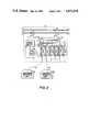
- FIG. 4is a block diagram of a data terminal input verification apparatus according to an embodiment of the present invention. As shown in FIG. 4, part of the data verification apparatus is included in external control unit 12 and part is included in typical subscriber processing unit 15a.
- Reference numeral 31denotes an input/output terminal which is connected to one terminal of 2-way splitter/distributor 27. Input/output terminal 31 is connected to bandpass filter 32 for separating and extracting the signals of FM audio band B3 and forward data band B4 from the remaining CATV signals. Input/output terminal 31 is also connected to the output terminal of lowpass filter (“LPF") 41 for band-limiting a reverse data transmission signal to band B5.
- LPFlowpass filter
- the output terminal of bandpass filter 32is connected to (a) data separation circuit 33 for separating and extracting the forward data transmission signal in band B4, and (b) FM separation circuit 36 for separating and extracting the FM audio signal of band B3.
- the output terminal of data separation circuit 33is connected to a data detector (demodulator) 34.
- Data detector 34detects forward data transmitted from the head end using frequency modulation and generates a digital signal output of logical "0" or "1". This digital data signal is supplied to microcomputer (“CPU") 35.
- the output terminal of FM separation circuit 36is connected to splitter/distributor 37. Distributor 37 supplies the FM signal extracted by FM separation circuit 36 to one input terminal of two-way distributor 45.
- CPU 35In addition to receiving forward data transmitted by the head end, CPU 35 causes reverse digital data to be transmited from external control unit 12 to the head end.
- the reverse datais sent to modulator 38 which modulates the data using binary phase-shift keying ("BPSK").
- BPSKbinary phase-shift keying
- the modulated reverse datais supplied to bandpass filter 39 through distributor 37.
- the data signalis filtered by filter 39 and is supplied through switch 40, lowpass filter 41, input/output terminal 31, and two-way splitter/distributor 27 to feeder line 11.
- Switch 40is controlled in response to an ON/OFF control signal generated by CPU 35.
- CPU 35supplies channel selection or tuning data to converter/tuner 43 contained, e.g., within subscriber unit 16a (FIG. 3).
- CATV signalsincluding signals from bands B1 and B2 (FIG. 2), are supplied to converter/tuner 43 through splitter/distributor 28 and switch 42.
- the television signal selected or tuned by converter/tuner 43is supplied to the other input terminal of two-way mixer 45 through directional coupler 44.
- Television signals from two-way mixer 45appear at a terminal 47 of external control unit 12 through capacitor 46.
- Reference numerals 48 and 49denote coils having high impedances against high frequency signals.
- a 468 KHz ASK data signal and an AC power signalare supplied from subscriber processing unit 15a via drop cable 14a to terminal 47 of external control unit 12.
- the purpose of capacitor 46 and coils 48 and 49is to separate the AC power coming up drop cable 14a from the CATV and data signals also transmitted by the drop cable.
- AC power signalsflow through coil 49 to common power source device 18 (FIG. 3), and very high-frequency televison, FM, and data signals flow through splitter/distributor 45.
- the 468 KHz data signal transmitted from subscriber processing unit 15ais supplied from terminal 47 to the common terminal of two-way splitter/distributor 53 through two-way distributor 45 and directional coupler 44.
- This data signalis demodulated by ASK demodulator 54 to provide digital ("1" and "0") data.
- the data demodulated by demodulator 54is supplied to CPU 35 through interface circuit 51.
- CPU 35also serves to transmit data to subscriber processing unit 15a. Such data is supplied from CPU 35 through interface circuit 51 to ASK modulator 52. The data from CPU 35 is thus modulated to an ASK signal wherein a "1" is represented by the presence of carrier and a "0" is represented by the absence of carrier. This ASK signal is transmitted through two-way distributor 53, directional coupler 44, and two-way distributor 45 to terminal 47.
- the ASK signal appearing at terminal 47is supplied to terminal 55 of subscriber processing unit 15a through drop cable 14a.
- the ASK signal appearing at terminal 55is supplied to the common input terminal of two-way distributor 62 through capacitor 56 and directional coupler 58.
- the AC power signalis applied to drop cable 14 via inductor 69 and capacitor 70.
- Capacitor 56 and inductor 57prevent this power signal from being applied to directional coupler 58 but pass higher frequency television, FM audio and ASK data signals between terminal 55 and directional coupler 58.
- the ASK data signal transmitted from external control unit 12is supplied from one output terminal of two-way distributor 62 to ASK demodulator 63.
- the output of ASK demodulator 63is digital data which is supplied to CPU 64 in subscriber processing unit 15a.
- CPU 64decodes and processes the digital data.
- the dataincludes display data corresponding to a channel request entered by the suscriber on a keypad of subscriber processing unit 15a.
- CPU 64also produces data corresponding to a tuning request signal. This output data is supplied to ASK modulator 65.
- the resulting 430 KHz ASK signal from ASK modulator 65appears at terminal 55 through two-way distributor 62, directional coupler 58, and capacitor 56.
- the 430 KHz ASK signalis then transmitted to terminal 47 of external control unit 12 through drop cable 14a.
- the output from directional coupler 58is supplied to two-way distributor 59.
- the signals supplied to distributor 59are the television signal selected by converter/tuner 43 and the FM audio signal separated by FM separation circuit 36.
- the distribution output terminals of two-way distributor 59are coupled to the subscriber's television receiver 61 and FM demodulator (radio receiver) 60, respectively.
- Reference numeral 66denotes a keyboard, which may be a conventional row and column matrix keyboard. Keyboard 66 has 10 numeric keys from 0 to 9. When the subscriber depresses any one of the keys, a signal corresponding to the depressed key appears on a particular row and column. This signal is read by CPU 64. When CPU 64 receives the signal (request signal) from keyboard 66, CPU 64 transmits a request signal to external control unit 12 by means of the 430 KHz data signals described above.
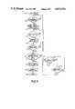
- FIG. 5is a flow chart of a program stored in CPU 64 to control data communication conditions between CPUs 35 and 64.
- step S11a key input at keyboard 66 of subscriber processing unit 15a is read by CPU 64. If a key has been pressed, CPU 64 reads the keyboard entry and proceeds to step S12.
- step S12CPU 64 checks whether or not data communication request transmission is enabled. If not, CPU 64 loops until data transmission is enabled. Otherwise, the flow advances to step S13.
- step S13CPU 64 provides a communication request signal to ASK modulator 65.
- Modulator 65ASK modulates the request signal on a 468 KHz carrier and transmits the signal to external control unit 12. At external control unit 12, the communication request signal is demodulated by ASK demodulator 54.
- the demodulated signalis supplied to CPU 35 via interface circuit 51.
- CPU 35detects the communications request signal from CPU 64 of subscriber processing unit 15a, CPU 35 transmits a data request or designation signal (including data which uniquely identifies subscriber processing unit 15a) to subscriber processing unit 15a by means of the 430 KHz data signals described above.
- CPU 64continuously transmits the communication request signal to external control unit 12 until CPU 35 transmits a signal designating subscriber processing unit 15a.
- Data uniquely identifying subscriber processing unit 15ais included in the data request or designation signal so that two or more substantially independent subscriber processing units, each having a different and unique address, can be connected to a single drop cable if desired. In this way, a single subscriber can have two subscriber processing units, each attached to a different one of two television receivers, to independently request and simultaneously receive two different television channels via a single drop cable.
- step S14When CPU 64 receives and decodes (step S14) a designation signal which includes data identifying subscriber processing unit 15a, CPU 64 starts transmission of the digital tuning request signal (step S15) via the 468 KHz data channel.
- CPU 35receives the tuning request signal data
- CPU 35sends back to CPU 64 via the 430 KHz data channel answer back or echo back (verification) data having the same content as the received data.
- step S16CPU 64 compares that data with the tuning request signal data (step S17). If the verification data is identical to the tuning request signal data, the flow advances to step S18, and the tuning request signal data is retransmitted by CPU 64 to CPU 35.
- the routinethen advances to step S19.
- step S19the verification data received by CPU 64 is supplied to latch circuit 67 (FIG. 4).
- the verification datais then displayed on display 68, which may be one or more conventional seven-segment displays, and the flow is ended (step S20).
- step S17if the verification data is not identical to the tuning request signal data, the program flow branches to step S21.
- step S21CPU 64 awaits retransmission of a designation signal from CPU 35. That is, CPU 64 checks whether or not subscriber processing unit 15a is still designated by CPU 35. If CPU 64 determines in step S21 that the designation signal for subscriber processing unit 15a from CPU 35 is present, the program flow returns to step S14 so that CPU 64 may again transmit its data to CPU 35. Otherwise, step S21 causes the program flow to advance to step S22.
- step S22CPU 64 checks whether or not another subscriber processing unit (e.g., unit 16b) has been designated to communicate with CPU 35. If NO in step S22, the routine returns to step S21, and if YES, the flow returns to step S12.
- another subscriber processing unite.g., unit 16b
- FIG. 6is a block diagram showing the detailed configuration of an embodiment of the invention.
- part of a typical subscriber processing unitis denoted as item 15a
- part of an associated external control unitis denoted as item 12.
- keyboard 71may, for example, be a conventional matrix keyboard, and decoder 72 may be a conventional decoder for converting the row and column input of keyboard 71 to parallel digital data.
- the digital data output by decoder 72is latched in latch circuit 73. If the latched data is channel tuning data (i.e., a number in the range 0 to 9), this tuning data is detected by channel designation bit number detector 74. Detector 74 is operated for a predetermined time interval after keyboard 71 is operated.
- latch circuit 73is cleared by detector 74. If proper channel designation data is latched by circuit 73, detector 74 supplies a detection (read) pulse to temporary memory 75 and to ON control terminal of switch 76. The detection pulse causes channel designation data latched in latch circuit 73 to be transferred to temporary memory 75.
- the detection pulse applied to the ON terminal of switch 76causes switch 76 to turn on and to connect a read clock signal ("CK") to communication request data memory 77.
- CKread clock signal
- Application of the CK signal to memory 77causes memory 77 to output a pre-determined sequence of digital bits representative of a unique communication request signal.
- This communication request datais supplied to ASK modulator 78, which modulates a 468 KHz carrier signal with the digital communication request data.
- ASK modulator 78applies the modulated signal to drop cable 79, which in turn transmits the signal to external control unit 12.
- the communication request datais demodulated by ASK demodulator 80, which in turn supplies the signal to communication request data register 81.
- ASK demodulator 80When the communication request data is properly stored in the register 81, the data is detected by communication request data detector 82.
- Communication request data detector 82generates a detect signal of "1" when it detects the unique communication request data, and a "0" if such data is not detected.
- the detect signalis stored in detection signal memory 83.
- the content of detection signal memory 83is read by circulating search register 84.
- detection signal memory 83contains a logical "1”
- the detection signalis supplied to "1" detector 85 which supplies an OFF signal to switch 86 to interrupt the passage of clock (“CK”) signals to circulating search register 84.
- CKclock
- Detector 85supplies a clear signal to detection signal memory 83 and an ON signal to switch 87.
- Designation data from designation data memory 88is supplied to ASK modulator 89 through switch 87.
- the designation data from memory 88is a predetermined digital code associated with the particular subscriber processing unit 15a which sent the communication request signal.
- ASK modulator 89modulates a 430 KHz carrier signal with the designation data for transmission to subscriber processing unit 15a via drop cable 79.
- ASK demodulator 90receives and demodulates this designation data.
- the predetermined code of the designation datais then detected by designation data detector 91.
- a detection pulseis supplied (a) as an OFF signal to switch 76, and (b) as an ON signal to switch 92.
- the OFF signalinterrupts the read clock signal from clocking communication request data memory 77, thus terminating transmission of communication request data to external control unit 12.
- the ON signalenables a data read clock signal to be supplied to temporary memory 75 through switch 92.
- temporary memory 75contains the channel designation data entered by the subscriber.
- the channel designation data stored in temporary memory 75has a predetermined number of bits.
- the clock pulses supplied to temporary memory 75are counted by bit counter 93. When the count of bit counter 93 has reached a value corresponding to the predetermined number of bits of the channel designation data, switch 92 is turned off in response to an output from bit counter 93.
- the clock pulses passed by switch 92 to bit counter 93 and temporary memory 75cause the channel designation data stored in temporary memory 75 to be read out as serial data. These data are supplied to ASK modulator 78.
- the serial dataare modulated by ASK modulator 78 and transmitted to external control unit 12 as a channel request signal.
- the channel request signalis supplied to ASK demodulator 80, where the signal is demodulated.
- the start portion of the channel designation dataincludes a predetermined channel data transmission code.
- the channel data transmission codeis detected by channel data transmission code detector 94.
- channel data transmission code detector 94detects the channel data transmission code, it supplies a detection output as an ON signal for turning on switch 95 and as an OFF signal for turning off switch 87.
- the transmission by external control unit 12 of designation data(via memory 88) is thus stopped, and a read clock is supplied to channel designation data register 96 through switch 95.
- switch 95allows the passage of a number of clock pulses equaling that number of bits. This is accomplished by bit counter 97. Each clock pulse passed is counted by bit counter 97. When the count of bit counter 97 reaches the predetermined value, an output from bit counter 97 is used to turn off switch 95. The result of this operation is that data register 96 holds the transmitted channel designation data.
- the output from bit counter 97is also supplied as a latch pulse to latch circuit 98 and as an ON signal to the control terminal of switch 100 through delay circuit 99.
- latch circuit 98latches the channel designation data stored in channel designation data register 96.
- the data latched by latch circuit 98is used as the answer back or verification data. More particularly, when switch 100 is turned on, a clock ("CK") signal is supplied to latch circuit 98.
- the channel designation datais then supplied as serial data from latch circuit 98 to ASK modulator 89. This serial data is then ASK modulated by ASK modulator 89 onto a 430 KHz carrier for transmission over drop cable 79 to subscriber processing unit 15a.
- the start portion of the channel designation dataincludes a unique answer back transmission code, and the number of bits of data read out from latch 98 is predetermined.
- the read clocksare counted by bit counter 101.
- bit counter 101When the count of bit counter 101 has reached a value corresponding to the predetemined number of bits of data read out from latch circuit 98, bit counter 101 generates a signal which turns off switch 100, thus interrupting the clock pulses clocking latch 98.
- the signal from bit counter 101is also used to turn ON switch 86, thus enabling operation of circulating search register 84.
- the modulated answer back datais received and demodulated by ASK demodulator 90.
- the start portion of the answer back dataincludes the answer back data transmission code. This unique code is detected by echo back data transmission code detector 102.
- detector 102When detector 102 detects the echo back data transmission code, detector 102 provides a detection pulse to turn ON switch 103.
- switch 103When switch 103 is turned on, a read clock ("CK") signal is supplied to echo back data register 104 to cause register 104 to store the ASK demodulated echo back data.
- CKread clock
- bit counter 105Because the number of bits of echo back data is predetermined, bit counter 105 counts the number of read clocks until the count of counter 105 reaches a value corresponding to the predetermined number of bits of the echo back data. When the count has reached this predetermined number, bit counter 105 generates a signal to turn OFF switch 103, and as a comparison start pulse for conventional comparator 106.
- the output data from temporary memory 75(which stored the channel designation data entered by the subscriber) is supplied to one input terminal of comparator 106, and the echo back data from echo back data register 104 is supplied to the other input terminal thereof. If the contents of temporary memory 75 and echo back data register 104 are the same, comparator 106 produces a signal to conventional gate 107 to render gate 107 conductive. This causes the contents of echo back data register 104 to pass to conventional display 108. Thus, the subscriber can determine that converter/tuner 43 (FIG. 4) in external control unit 12 has properly tuned to the requested channel.
- Error data generator 108may, for example, be a conventional read-only memory containing data representing a predetermined error code. Upon receipt of the error pulse, error data is supplied to display 108 and displayed. Thus, the subscriber can determine that external control unit 12 did not tune to the requested channel.
Landscapes
- Engineering & Computer Science (AREA)
- Signal Processing (AREA)
- Multimedia (AREA)
- Computer Networks & Wireless Communication (AREA)
- Two-Way Televisions, Distribution Of Moving Picture Or The Like (AREA)
Abstract
Description
Claims (7)
Priority Applications (1)
| Application Number | Priority Date | Filing Date | Title |
|---|---|---|---|
| US06/615,778US4673976A (en) | 1984-05-31 | 1984-05-31 | Cable television system data verification apparatus |
Applications Claiming Priority (1)
| Application Number | Priority Date | Filing Date | Title |
|---|---|---|---|
| US06/615,778US4673976A (en) | 1984-05-31 | 1984-05-31 | Cable television system data verification apparatus |
Publications (1)
| Publication Number | Publication Date |
|---|---|
| US4673976Atrue US4673976A (en) | 1987-06-16 |
Family
ID=24466776
Family Applications (1)
| Application Number | Title | Priority Date | Filing Date |
|---|---|---|---|
| US06/615,778Expired - LifetimeUS4673976A (en) | 1984-05-31 | 1984-05-31 | Cable television system data verification apparatus |
Country Status (1)
| Country | Link |
|---|---|
| US (1) | US4673976A (en) |
Cited By (43)
| Publication number | Priority date | Publication date | Assignee | Title |
|---|---|---|---|---|
| US4754426A (en)* | 1984-05-31 | 1988-06-28 | American Television & Communications Corporation | System for controlling communications on a cable television network |
| US4760597A (en)* | 1985-04-16 | 1988-07-26 | General Electric Company | Technician set-up unit for and method of cable television converter installation and address assignment |
| US4809325A (en)* | 1984-11-29 | 1989-02-28 | Sony Corporation | Receiver for pay television |
| US4837820A (en)* | 1986-10-17 | 1989-06-06 | Zenith Electronics Corporation | Hybrid CATV scrambling system |
| US4901367A (en)* | 1988-11-30 | 1990-02-13 | Victor Nicholson | Cable communications system with remote switching and processing converters |
| FR2637755A1 (en)* | 1988-10-10 | 1990-04-13 | Esys Sa | INTERACTIVE TELEDISTRIBUTION NETWORK WITH ARBORESCENT ARCHITECTURE |
| US5014309A (en)* | 1988-03-10 | 1991-05-07 | Scientific-Atlanta, Inc. | Off-premises cable television channel interdiction method and apparatus |
| US5016246A (en)* | 1989-12-29 | 1991-05-14 | Hubbell Incorporated | Digital telephone system circuits |
| US5081628A (en)* | 1988-09-17 | 1992-01-14 | Hitachi, Ltd. | Cordless keyboard |
| US5093921A (en)* | 1989-12-19 | 1992-03-03 | Comband Technologies, Inc. | Initialization technique and apparatus for set top converters |
| EP0410987A4 (en)* | 1988-04-01 | 1992-04-15 | Scientific Atlanta, Inc. | Set-top interface transactions in an impulse pay per view television system |
| US5159684A (en)* | 1989-05-24 | 1992-10-27 | Pitney Bowes Inc. | Data communication interface integrated circuit with data-echoing and non-echoing communication modes |
| US5245420A (en)* | 1990-11-27 | 1993-09-14 | Scientific-Atlanta, Inc. | CATV pay per view interdiction system |
| US5303295A (en)* | 1988-03-10 | 1994-04-12 | Scientific-Atlanta, Inc. | Enhanced versatility of a program control by a combination of technologies |
| US5331412A (en)* | 1990-11-27 | 1994-07-19 | Scientific-Atlanta, Inc. | Tamper resistant apparatus for a CATV system |
| US5455911A (en)* | 1993-04-05 | 1995-10-03 | Allen-Bradley Company, Inc. | Communications protocol for use in transferring data over a serial bus |
| US5505901A (en)* | 1988-03-10 | 1996-04-09 | Scientific-Atlanta, Inc. | CATV pay per view interdiction system method and apparatus |
| US5574495A (en)* | 1995-10-18 | 1996-11-12 | General Instrument Corporation | Cable television data path error analyzer located at the set-top terminal |
| US5649283A (en)* | 1995-09-28 | 1997-07-15 | Lucent Technologies Inc. | Program verification for cable television at a consumer location |
| US5699105A (en)* | 1995-09-28 | 1997-12-16 | Lucent Technologies Inc. | Curbside circuitry for interactive communication services |
| US5926547A (en)* | 1997-03-05 | 1999-07-20 | Scientific-Atlanta, Inc. | Method and apparatus for providing program/component redundancy in headend |
| US6286142B1 (en)* | 1996-02-23 | 2001-09-04 | Alcatel Usa, Inc. | Method and system for communicating video signals to a plurality of television sets |
| US20020042923A1 (en)* | 1992-12-09 | 2002-04-11 | Asmussen Michael L. | Video and digital multimedia aggregator content suggestion engine |
| US20030212998A1 (en)* | 2002-05-09 | 2003-11-13 | Radiant Communications Corporation | Channel transmitter unit |
| US20030210352A1 (en)* | 2002-05-09 | 2003-11-13 | Fitzsimmons John E. | Remote monitoring system |
| US20040088733A1 (en)* | 2002-11-04 | 2004-05-06 | Havens Daniel W. | Broadband network test system and method |
| US6804828B1 (en)* | 1998-12-03 | 2004-10-12 | Masprodenkoh Kabushikikaisha | Tap device of cable broadcasting system |
| US20060190980A1 (en)* | 2003-07-14 | 2006-08-24 | Sony Corporation | Information processing device, information processing method, and information processing program |
| US7299501B2 (en) | 1993-12-02 | 2007-11-20 | Discovery Communications, Inc. | Electronic book selection and delivery system having encryption and security features |
| US7336788B1 (en) | 1992-12-09 | 2008-02-26 | Discovery Communicatoins Inc. | Electronic book secure communication with home subsystem |
| US7401286B1 (en) | 1993-12-02 | 2008-07-15 | Discovery Communications, Inc. | Electronic book electronic links |
| US7509270B1 (en) | 1992-12-09 | 2009-03-24 | Discovery Communications, Inc. | Electronic Book having electronic commerce features |
| US7716349B1 (en) | 1992-12-09 | 2010-05-11 | Discovery Communications, Inc. | Electronic book library/bookstore system |
| US7835989B1 (en) | 1992-12-09 | 2010-11-16 | Discovery Communications, Inc. | Electronic book alternative delivery systems |
| US7849393B1 (en) | 1992-12-09 | 2010-12-07 | Discovery Communications, Inc. | Electronic book connection to world watch live |
| US7861166B1 (en) | 1993-12-02 | 2010-12-28 | Discovery Patent Holding, Llc | Resizing document pages to fit available hardware screens |
| US7865567B1 (en) | 1993-12-02 | 2011-01-04 | Discovery Patent Holdings, Llc | Virtual on-demand electronic book |
| US20110085080A1 (en)* | 2001-08-03 | 2011-04-14 | Comcast Ip Holdings I, Llc | Video and digital multimedia aggregator content coding and formatting |
| US8073695B1 (en) | 1992-12-09 | 2011-12-06 | Adrea, LLC | Electronic book with voice emulation features |
| US8095949B1 (en) | 1993-12-02 | 2012-01-10 | Adrea, LLC | Electronic book with restricted access features |
| US8621521B2 (en) | 2001-08-03 | 2013-12-31 | Comcast Ip Holdings I, Llc | Video and digital multimedia aggregator |
| US9053640B1 (en) | 1993-12-02 | 2015-06-09 | Adrea, LLC | Interactive electronic book |
| US9078014B2 (en) | 2000-06-19 | 2015-07-07 | Comcast Ip Holdings I, Llc | Method and apparatus for targeting of interactive virtual objects |
Citations (34)
| Publication number | Priority date | Publication date | Assignee | Title |
|---|---|---|---|---|
| US3050712A (en)* | 1959-02-13 | 1962-08-21 | Avco Corp | Wired program distribution system |
| US3230302A (en)* | 1959-02-13 | 1966-01-18 | Avco Mfg Corp | Television program distribution and metering system |
| US3387082A (en)* | 1963-12-23 | 1968-06-04 | Hazeltine Research Inc | Pay television audience survey and billing system |
| US3668307A (en)* | 1970-03-30 | 1972-06-06 | Kms Ind Inc | Two-way community antenna television system |
| US3733430A (en)* | 1970-12-28 | 1973-05-15 | Rca Corp | Channel monitoring system |
| US3757035A (en)* | 1970-04-21 | 1973-09-04 | Skiatron Elect & Tele | Interrogated transponder system |
| US3786424A (en)* | 1972-02-22 | 1974-01-15 | Coaxial Scient Corp | Communications system for data transmission and retrieval |
| US3803491A (en)* | 1971-05-26 | 1974-04-09 | Tocom | Communications system |
| US3805234A (en)* | 1972-07-31 | 1974-04-16 | Westinghouse Electric Corp | Digital data transmission system |
| US3859596A (en)* | 1972-11-24 | 1975-01-07 | Computer Cable Corp | Cable television two-way communication system |
| US3987397A (en)* | 1975-04-25 | 1976-10-19 | Belcher Brian E | Remote unit for a two-way cable communications system |
| US3990012A (en)* | 1975-04-25 | 1976-11-02 | Tocom, Inc. | Remote transceiver for a multiple site location in a two-way cable television system |
| US3993995A (en)* | 1975-12-08 | 1976-11-23 | Rca Corporation | Respiration monitor |
| US4002843A (en)* | 1973-12-17 | 1977-01-11 | Rackman Michael I | Tamper-proof two-way cable system |
| US4030072A (en)* | 1974-12-18 | 1977-06-14 | Xerox Corporation | Computer system operation and control |
| US4082922A (en)* | 1977-02-22 | 1978-04-04 | Chu Wesley W | Statistical multiplexing system for computer communications |
| US4118669A (en)* | 1976-10-15 | 1978-10-03 | Premier Cablevision, Limited | Remote disconnect-reconnect tap for cable television systems |
| US4156847A (en)* | 1976-04-16 | 1979-05-29 | Pioneer Electronic Corporation | Method and apparatus for confirming transmission in bidirectional CATV system |
| EP0019287A1 (en)* | 1979-05-18 | 1980-11-26 | Tocom, Inc. | Data communications system |
| US4290142A (en)* | 1978-02-22 | 1981-09-15 | Heinrich-Hertz-Institut Fur Nachrichtentechnik Berlin Gmbh | Interactive cable television system |
| US4322854A (en)* | 1979-05-18 | 1982-03-30 | Allan B. Bundens | Data communications terminal |
| US4343042A (en)* | 1979-07-10 | 1982-08-03 | Cablebus Systems Corporation | Bi-directional data transmission and control system |
| US4351059A (en)* | 1979-09-18 | 1982-09-21 | Lignes Telegraphiques Et Telephoniques | Method for testing a digital data transmission line between two modems and a device for the application of said method |
| US4361903A (en)* | 1979-08-16 | 1982-11-30 | Pioneer Electronic Corporation | Data transmission process in a CATV system |
| EP0103438A1 (en)* | 1982-09-07 | 1984-03-21 | Thorn Emi Plc | Television and distribution network |
| US4450481A (en)* | 1981-08-25 | 1984-05-22 | E-Com Corporation | Tamper-resistant, expandable communications system |
| US4455538A (en)* | 1981-08-26 | 1984-06-19 | Siemens Aktiengesellschaft | Subassembly, in particular a choke and a filter for radio interference control |
| US4466001A (en)* | 1981-12-04 | 1984-08-14 | Motorola, Inc. | Polling system for multiple terminal units |
| US4475123A (en)* | 1981-04-02 | 1984-10-02 | Theta-Com., Division Of Texscan | Addressable subscriber cable television system |
| US4484218A (en)* | 1980-04-30 | 1984-11-20 | The Manitoba Telephone System | Video distribution control system |
| US4494111A (en)* | 1981-12-07 | 1985-01-15 | General Instrument Corporation | Frequency agile security apparatus |
| US4520508A (en)* | 1982-12-21 | 1985-05-28 | General Instrument Corporation | Subscriber terminal for monitoring radio-frequency signal ingress into cable television systems |
| US4530008A (en)* | 1983-10-03 | 1985-07-16 | Broadband Technologies, Inc. | Secured communications system |
| US4533948A (en)* | 1982-04-30 | 1985-08-06 | General Instrument Corporation | CATV Communication system |
- 1984
- 1984-05-31USUS06/615,778patent/US4673976A/ennot_activeExpired - Lifetime
Patent Citations (34)
| Publication number | Priority date | Publication date | Assignee | Title |
|---|---|---|---|---|
| US3050712A (en)* | 1959-02-13 | 1962-08-21 | Avco Corp | Wired program distribution system |
| US3230302A (en)* | 1959-02-13 | 1966-01-18 | Avco Mfg Corp | Television program distribution and metering system |
| US3387082A (en)* | 1963-12-23 | 1968-06-04 | Hazeltine Research Inc | Pay television audience survey and billing system |
| US3668307A (en)* | 1970-03-30 | 1972-06-06 | Kms Ind Inc | Two-way community antenna television system |
| US3757035A (en)* | 1970-04-21 | 1973-09-04 | Skiatron Elect & Tele | Interrogated transponder system |
| US3733430A (en)* | 1970-12-28 | 1973-05-15 | Rca Corp | Channel monitoring system |
| US3803491A (en)* | 1971-05-26 | 1974-04-09 | Tocom | Communications system |
| US3786424A (en)* | 1972-02-22 | 1974-01-15 | Coaxial Scient Corp | Communications system for data transmission and retrieval |
| US3805234A (en)* | 1972-07-31 | 1974-04-16 | Westinghouse Electric Corp | Digital data transmission system |
| US3859596A (en)* | 1972-11-24 | 1975-01-07 | Computer Cable Corp | Cable television two-way communication system |
| US4002843A (en)* | 1973-12-17 | 1977-01-11 | Rackman Michael I | Tamper-proof two-way cable system |
| US4030072A (en)* | 1974-12-18 | 1977-06-14 | Xerox Corporation | Computer system operation and control |
| US3987397A (en)* | 1975-04-25 | 1976-10-19 | Belcher Brian E | Remote unit for a two-way cable communications system |
| US3990012A (en)* | 1975-04-25 | 1976-11-02 | Tocom, Inc. | Remote transceiver for a multiple site location in a two-way cable television system |
| US3993995A (en)* | 1975-12-08 | 1976-11-23 | Rca Corporation | Respiration monitor |
| US4156847A (en)* | 1976-04-16 | 1979-05-29 | Pioneer Electronic Corporation | Method and apparatus for confirming transmission in bidirectional CATV system |
| US4118669A (en)* | 1976-10-15 | 1978-10-03 | Premier Cablevision, Limited | Remote disconnect-reconnect tap for cable television systems |
| US4082922A (en)* | 1977-02-22 | 1978-04-04 | Chu Wesley W | Statistical multiplexing system for computer communications |
| US4290142A (en)* | 1978-02-22 | 1981-09-15 | Heinrich-Hertz-Institut Fur Nachrichtentechnik Berlin Gmbh | Interactive cable television system |
| EP0019287A1 (en)* | 1979-05-18 | 1980-11-26 | Tocom, Inc. | Data communications system |
| US4322854A (en)* | 1979-05-18 | 1982-03-30 | Allan B. Bundens | Data communications terminal |
| US4343042A (en)* | 1979-07-10 | 1982-08-03 | Cablebus Systems Corporation | Bi-directional data transmission and control system |
| US4361903A (en)* | 1979-08-16 | 1982-11-30 | Pioneer Electronic Corporation | Data transmission process in a CATV system |
| US4351059A (en)* | 1979-09-18 | 1982-09-21 | Lignes Telegraphiques Et Telephoniques | Method for testing a digital data transmission line between two modems and a device for the application of said method |
| US4484218A (en)* | 1980-04-30 | 1984-11-20 | The Manitoba Telephone System | Video distribution control system |
| US4475123A (en)* | 1981-04-02 | 1984-10-02 | Theta-Com., Division Of Texscan | Addressable subscriber cable television system |
| US4450481A (en)* | 1981-08-25 | 1984-05-22 | E-Com Corporation | Tamper-resistant, expandable communications system |
| US4455538A (en)* | 1981-08-26 | 1984-06-19 | Siemens Aktiengesellschaft | Subassembly, in particular a choke and a filter for radio interference control |
| US4466001A (en)* | 1981-12-04 | 1984-08-14 | Motorola, Inc. | Polling system for multiple terminal units |
| US4494111A (en)* | 1981-12-07 | 1985-01-15 | General Instrument Corporation | Frequency agile security apparatus |
| US4533948A (en)* | 1982-04-30 | 1985-08-06 | General Instrument Corporation | CATV Communication system |
| EP0103438A1 (en)* | 1982-09-07 | 1984-03-21 | Thorn Emi Plc | Television and distribution network |
| US4520508A (en)* | 1982-12-21 | 1985-05-28 | General Instrument Corporation | Subscriber terminal for monitoring radio-frequency signal ingress into cable television systems |
| US4530008A (en)* | 1983-10-03 | 1985-07-16 | Broadband Technologies, Inc. | Secured communications system |
Non-Patent Citations (40)
| Title |
|---|
| "Application Note Deltakabel Starnetwork Coaxial Version", by DeltaKabel bv. |
| "ATC, Toshiba Announce Plans to Produce New Cable Product", ATC News, Nov. 10, 1982. |
| "Cable Television in Broadband Systems", by DeltaKabel bv. |
| "DST Unit Offers Cable Industry Desirable Features", ATC News, Nov. 10, 1982. |
| "High-Speed Polling System for Multi Purpose CATV", by Ken'ichi Hiratsuka et al., Japan Telecommunications Review, Jan. 1977, pp. 20-28. |
| "Jerrold Introduces STARCOM IntraNet a Cost-Effective Off-Premises Addressable Converter System", by General Instrument. |
| "Just in Time for the Future", by Pico Products Inc. |
| "Kabel tv Experimenten Limburg", by DeltaKabel bv. |
| "Mini-Hub Addressable Distribution System for Hi-Rise Application", M. F. Mesiya, IEEE 1982. |
| "Mini-Star Network with Selection Facilities and Computer Control", by DeltaKabel bv. |
| "Out Of-Home Addressable Security is Now a Reality", by Vitek Electronics, Inc. |
| "Packetcable: A New Interactive Cable System Technology", by Paul Baran, 31st Annual NCTA Convention Official Transcript, 1982. |
| "Plessey Scientific-Atlanta Multistar System Technical Description". |
| "SCAT Series 10 Converter Off-Premises Addressable Control: Second Generation", by Joseph P. Preschutti. |
| "The Next Generation in Cable Systems", by Times Fiber Communications, Inc. |
| "The Subscriber Response System", by R. T. Callais et al., 20th Annual NCTA Convention Official Transcript, Jul. 1971, pp. 28-48. |
| "The Total Communication Concept for the Future", by E. J. Gargini, The Royal Television Society Journal, Mar./Apr. 1973, pp. 182-193. |
| "Tocom System Bi-Directional Cable Television Information and Control Transmission System", by William F. Osborn, 20th Annual NCTA Convention Official Transcript, Jul. 1971, pp. 507-529. |
| "Two Way Cable Experiment", Limburg International Magazine, vol. 3, No. 2, Apr./May 1982, pp. cover, 2, 7-9, 24-25. |
| "Two-Way Applications for Cable Television Systems in the '70s", IEEE Spectrum, Nov. 1971, pp. 39-54. |
| Application Note Deltakabel Starnetwork Coaxial Version , by DeltaKabel bv.* |
| ATC, Toshiba Announce Plans to Produce New Cable Product , ATC News, Nov. 10, 1982.* |
| Cable Television in Broadband Systems , by DeltaKabel bv.* |
| DST Unit Offers Cable Industry Desirable Features , ATC News, Nov. 10, 1982.* |
| High Speed Polling System for Multi Purpose CATV , by Ken ichi Hiratsuka et al., Japan Telecommunications Review, Jan. 1977, pp. 20 28.* |
| Jerrold Introduces STARCOM IntraNet a Cost Effective Off Premises Addressable Converter System , by General Instrument.* |
| Just in Time for the Future , by Pico Products Inc.* |
| Kabel tv Experimenten Limburg , by DeltaKabel bv.* |
| Mini Hub Addressable Distribution System for Hi Rise Application , M. F. Mesiya, IEEE 1982.* |
| Mini Star Network with Selection Facilities and Computer Control , by DeltaKabel bv.* |
| Out Of Home Addressable Security is Now a Reality , by Vitek Electronics, Inc.* |
| Packetcable: A New Interactive Cable System Technology , by Paul Baran, 31 st Annual NCTA Convention Official Transcript, 1982.* |
| Plessey Scientific Atlanta Multistar System Technical Description .* |
| SCAT Series 10 Converter Off Premises Addressable Control: Second Generation , by Joseph P. Preschutti.* |
| The Next Generation in Cable Systems , by Times Fiber Communications, Inc.* |
| The Subscriber Response System , by R. T. Callais et al., 20 th Annual NCTA Convention Official Transcript, Jul. 1971, pp. 28 48.* |
| The Total Communication Concept for the Future , by E. J. Gargini, The Royal Television Society Journal, Mar./Apr. 1973, pp. 182 193.* |
| Tocom System Bi Directional Cable Television Information and Control Transmission System , by William F. Osborn, 20 th Annual NCTA Convention Official Transcript, Jul. 1971, pp. 507 529.* |
| Two Way Applications for Cable Television Systems in the 70s , IEEE Spectrum, Nov. 1971, pp. 39 54.* |
| Two Way Cable Experiment , Limburg International Magazine, vol. 3, No. 2, Apr./May 1982, pp. cover, 2, 7 9, 24 25.* |
Cited By (59)
| Publication number | Priority date | Publication date | Assignee | Title |
|---|---|---|---|---|
| US4754426A (en)* | 1984-05-31 | 1988-06-28 | American Television & Communications Corporation | System for controlling communications on a cable television network |
| US4809325A (en)* | 1984-11-29 | 1989-02-28 | Sony Corporation | Receiver for pay television |
| US4760597A (en)* | 1985-04-16 | 1988-07-26 | General Electric Company | Technician set-up unit for and method of cable television converter installation and address assignment |
| US4837820A (en)* | 1986-10-17 | 1989-06-06 | Zenith Electronics Corporation | Hybrid CATV scrambling system |
| US5014309A (en)* | 1988-03-10 | 1991-05-07 | Scientific-Atlanta, Inc. | Off-premises cable television channel interdiction method and apparatus |
| US5505901A (en)* | 1988-03-10 | 1996-04-09 | Scientific-Atlanta, Inc. | CATV pay per view interdiction system method and apparatus |
| US5303295A (en)* | 1988-03-10 | 1994-04-12 | Scientific-Atlanta, Inc. | Enhanced versatility of a program control by a combination of technologies |
| EP0410987A4 (en)* | 1988-04-01 | 1992-04-15 | Scientific Atlanta, Inc. | Set-top interface transactions in an impulse pay per view television system |
| US5081628A (en)* | 1988-09-17 | 1992-01-14 | Hitachi, Ltd. | Cordless keyboard |
| FR2637755A1 (en)* | 1988-10-10 | 1990-04-13 | Esys Sa | INTERACTIVE TELEDISTRIBUTION NETWORK WITH ARBORESCENT ARCHITECTURE |
| US5485196A (en)* | 1988-10-10 | 1996-01-16 | Lyonnaise Communications | Secure interactive program distribution control for teledistribution network |
| WO1991014343A1 (en)* | 1988-10-10 | 1991-09-19 | Elene S.A. | Interactive telebroadcasting network with tree architecture |
| US4901367A (en)* | 1988-11-30 | 1990-02-13 | Victor Nicholson | Cable communications system with remote switching and processing converters |
| US5159684A (en)* | 1989-05-24 | 1992-10-27 | Pitney Bowes Inc. | Data communication interface integrated circuit with data-echoing and non-echoing communication modes |
| US5093921A (en)* | 1989-12-19 | 1992-03-03 | Comband Technologies, Inc. | Initialization technique and apparatus for set top converters |
| US5016246A (en)* | 1989-12-29 | 1991-05-14 | Hubbell Incorporated | Digital telephone system circuits |
| US5245420A (en)* | 1990-11-27 | 1993-09-14 | Scientific-Atlanta, Inc. | CATV pay per view interdiction system |
| US5331412A (en)* | 1990-11-27 | 1994-07-19 | Scientific-Atlanta, Inc. | Tamper resistant apparatus for a CATV system |
| US7865405B2 (en) | 1992-12-09 | 2011-01-04 | Discovery Patent Holdings, Llc | Electronic book having electronic commerce features |
| US9286294B2 (en) | 1992-12-09 | 2016-03-15 | Comcast Ip Holdings I, Llc | Video and digital multimedia aggregator content suggestion engine |
| US8073695B1 (en) | 1992-12-09 | 2011-12-06 | Adrea, LLC | Electronic book with voice emulation features |
| US8060905B1 (en) | 1992-12-09 | 2011-11-15 | Comcast Ip Holdings I, Llc | Television delivery system having interactive electronic program guide |
| US7336788B1 (en) | 1992-12-09 | 2008-02-26 | Discovery Communicatoins Inc. | Electronic book secure communication with home subsystem |
| US7849393B1 (en) | 1992-12-09 | 2010-12-07 | Discovery Communications, Inc. | Electronic book connection to world watch live |
| US20020042923A1 (en)* | 1992-12-09 | 2002-04-11 | Asmussen Michael L. | Video and digital multimedia aggregator content suggestion engine |
| US7835989B1 (en) | 1992-12-09 | 2010-11-16 | Discovery Communications, Inc. | Electronic book alternative delivery systems |
| US7836481B1 (en) | 1992-12-09 | 2010-11-16 | Comcast Ip Holdings I, Llc | Set top terminal for generating an interactive electronic program guide for use with television delivery system |
| US7770196B1 (en) | 1992-12-09 | 2010-08-03 | Comcast Ip Holdings I, Llc | Set top terminal for organizing program options available in television delivery system |
| US7716349B1 (en) | 1992-12-09 | 2010-05-11 | Discovery Communications, Inc. | Electronic book library/bookstore system |
| US7509270B1 (en) | 1992-12-09 | 2009-03-24 | Discovery Communications, Inc. | Electronic Book having electronic commerce features |
| US5455911A (en)* | 1993-04-05 | 1995-10-03 | Allen-Bradley Company, Inc. | Communications protocol for use in transferring data over a serial bus |
| US7861166B1 (en) | 1993-12-02 | 2010-12-28 | Discovery Patent Holding, Llc | Resizing document pages to fit available hardware screens |
| US9053640B1 (en) | 1993-12-02 | 2015-06-09 | Adrea, LLC | Interactive electronic book |
| US8095949B1 (en) | 1993-12-02 | 2012-01-10 | Adrea, LLC | Electronic book with restricted access features |
| US7401286B1 (en) | 1993-12-02 | 2008-07-15 | Discovery Communications, Inc. | Electronic book electronic links |
| US7299501B2 (en) | 1993-12-02 | 2007-11-20 | Discovery Communications, Inc. | Electronic book selection and delivery system having encryption and security features |
| US7865567B1 (en) | 1993-12-02 | 2011-01-04 | Discovery Patent Holdings, Llc | Virtual on-demand electronic book |
| US5649283A (en)* | 1995-09-28 | 1997-07-15 | Lucent Technologies Inc. | Program verification for cable television at a consumer location |
| US5699105A (en)* | 1995-09-28 | 1997-12-16 | Lucent Technologies Inc. | Curbside circuitry for interactive communication services |
| US5574495A (en)* | 1995-10-18 | 1996-11-12 | General Instrument Corporation | Cable television data path error analyzer located at the set-top terminal |
| US5874992A (en)* | 1995-10-18 | 1999-02-23 | General Instrument Corporation | Cable television data bit path error analyzer |
| US6286142B1 (en)* | 1996-02-23 | 2001-09-04 | Alcatel Usa, Inc. | Method and system for communicating video signals to a plurality of television sets |
| US5926547A (en)* | 1997-03-05 | 1999-07-20 | Scientific-Atlanta, Inc. | Method and apparatus for providing program/component redundancy in headend |
| US6804828B1 (en)* | 1998-12-03 | 2004-10-12 | Masprodenkoh Kabushikikaisha | Tap device of cable broadcasting system |
| US9099097B2 (en) | 1999-06-25 | 2015-08-04 | Adrea, LLC | Electronic book with voice emulation features |
| US8548813B2 (en) | 1999-06-25 | 2013-10-01 | Adrea, LLC | Electronic book with voice emulation features |
| US9078014B2 (en) | 2000-06-19 | 2015-07-07 | Comcast Ip Holdings I, Llc | Method and apparatus for targeting of interactive virtual objects |
| US9813641B2 (en) | 2000-06-19 | 2017-11-07 | Comcast Ip Holdings I, Llc | Method and apparatus for targeting of interactive virtual objects |
| US8578410B2 (en) | 2001-08-03 | 2013-11-05 | Comcast Ip Holdings, I, Llc | Video and digital multimedia aggregator content coding and formatting |
| US20110085080A1 (en)* | 2001-08-03 | 2011-04-14 | Comcast Ip Holdings I, Llc | Video and digital multimedia aggregator content coding and formatting |
| US8621521B2 (en) | 2001-08-03 | 2013-12-31 | Comcast Ip Holdings I, Llc | Video and digital multimedia aggregator |
| US10140433B2 (en) | 2001-08-03 | 2018-11-27 | Comcast Ip Holdings I, Llc | Video and digital multimedia aggregator |
| US10349096B2 (en) | 2001-08-03 | 2019-07-09 | Comcast Ip Holdings I, Llc | Video and digital multimedia aggregator content coding and formatting |
| US20030212998A1 (en)* | 2002-05-09 | 2003-11-13 | Radiant Communications Corporation | Channel transmitter unit |
| US20030210352A1 (en)* | 2002-05-09 | 2003-11-13 | Fitzsimmons John E. | Remote monitoring system |
| US20030212994A1 (en)* | 2002-05-09 | 2003-11-13 | Radiant Communications Corporation | Remote monitoring system |
| US20040088733A1 (en)* | 2002-11-04 | 2004-05-06 | Havens Daniel W. | Broadband network test system and method |
| US8185924B2 (en)* | 2003-07-14 | 2012-05-22 | Sony Corporation | Information processing device, information processing method, and information processing program |
| US20060190980A1 (en)* | 2003-07-14 | 2006-08-24 | Sony Corporation | Information processing device, information processing method, and information processing program |
Similar Documents
| Publication | Publication Date | Title |
|---|---|---|
| US4673976A (en) | Cable television system data verification apparatus | |
| US4686564A (en) | Communication data processing device of cable television system | |
| US4245245A (en) | Interactive CATV system | |
| US4754426A (en) | System for controlling communications on a cable television network | |
| US4322745A (en) | Television signal scrambling method for CATV system | |
| US8631434B2 (en) | Method and apparatus for transmitting and downloading setup information | |
| US4684980A (en) | System for controlling communications on a cable television network | |
| US6583825B1 (en) | Method and apparatus for transmitting and downloading setup information | |
| GB2126002A (en) | Automatic control for recording apparatus | |
| EP0183626A2 (en) | Receiver for pay television | |
| US4677467A (en) | CATV addressable converter with multi-purpose, bi-directional serial digital data port | |
| JPS6330032A (en) | Cable broadcasting equipment | |
| JP2007181221A6 (en) | Method and apparatus for transmitting and downloading preparation information | |
| US5359419A (en) | Programmable CATV system and termainal unit therefor, including acknowledgement of program request | |
| EP0167237A2 (en) | Cable television system | |
| US4710956A (en) | Cable television system | |
| US4760597A (en) | Technician set-up unit for and method of cable television converter installation and address assignment | |
| JPS60253387A (en) | Reverse signal transmitter of cable television system | |
| US5485196A (en) | Secure interactive program distribution control for teledistribution network | |
| US4741048A (en) | One-way addressable system | |
| US4648122A (en) | Community antenna television communication system | |
| CA1171165A (en) | Fail-safe catv system center facility | |
| JPS60253386A (en) | Controller of cable television system | |
| JPS6127952B2 (en) | ||
| JPS61129939A (en) | Information receiver |
Legal Events
| Date | Code | Title | Description |
|---|---|---|---|
| AS | Assignment | Owner name:AMERICAN TELEVISION & COMMUNICATIONS CORPORATION 1 Free format text:ASSIGNMENT OF ASSIGNORS INTEREST.;ASSIGNOR:WREFORD-HOWARD, DAVID;REEL/FRAME:004267/0342 Effective date:19840529 Owner name:AMERICAN TELEVISION & COMMUNICATIONS CORPORATION,C Free format text:ASSIGNMENT OF ASSIGNORS INTEREST;ASSIGNOR:WREFORD-HOWARD, DAVID;REEL/FRAME:004267/0342 Effective date:19840529 | |
| STCF | Information on status: patent grant | Free format text:PATENTED CASE | |
| FPAY | Fee payment | Year of fee payment:4 | |
| AS | Assignment | Owner name:TIME WARNER ENTERTAINMENT COMPANY L.P., NEW YORK Free format text:ASSIGNMENT OF ASSIGNORS INTEREST.;ASSIGNOR:AMERICAN TELEVISION AND COMMUNICATIONS CORPORATION, A CORP. OF DE;REEL/FRAME:006243/0645 Effective date:19920630 | |
| FEPP | Fee payment procedure | Free format text:PAYOR NUMBER ASSIGNED (ORIGINAL EVENT CODE: ASPN); ENTITY STATUS OF PATENT OWNER: LARGE ENTITY | |
| FPAY | Fee payment | Year of fee payment:8 | |
| FPAY | Fee payment | Year of fee payment:12 | |
| REMI | Maintenance fee reminder mailed |