US4673820A - Drop detecting system with focusing mirror element and vibrator - Google Patents
Drop detecting system with focusing mirror element and vibratorDownload PDFInfo
- Publication number
- US4673820A US4673820AUS06/669,108US66910884AUS4673820AUS 4673820 AUS4673820 AUS 4673820AUS 66910884 AUS66910884 AUS 66910884AUS 4673820 AUS4673820 AUS 4673820A
- Authority
- US
- United States
- Prior art keywords
- drop
- detector
- light
- drip chamber
- mirror
- Prior art date
- Legal status (The legal status is an assumption and is not a legal conclusion. Google has not performed a legal analysis and makes no representation as to the accuracy of the status listed.)
- Expired - Fee Related
Links
Images


Classifications
- A—HUMAN NECESSITIES
- A61—MEDICAL OR VETERINARY SCIENCE; HYGIENE
- A61M—DEVICES FOR INTRODUCING MEDIA INTO, OR ONTO, THE BODY; DEVICES FOR TRANSDUCING BODY MEDIA OR FOR TAKING MEDIA FROM THE BODY; DEVICES FOR PRODUCING OR ENDING SLEEP OR STUPOR
- A61M5/00—Devices for bringing media into the body in a subcutaneous, intra-vascular or intramuscular way; Accessories therefor, e.g. filling or cleaning devices, arm-rests
- A61M5/14—Infusion devices, e.g. infusing by gravity; Blood infusion; Accessories therefor
- A61M5/168—Means for controlling media flow to the body or for metering media to the body, e.g. drip meters, counters ; Monitoring media flow to the body
- A61M5/16886—Means for controlling media flow to the body or for metering media to the body, e.g. drip meters, counters ; Monitoring media flow to the body for measuring fluid flow rate, i.e. flowmeters
- A61M5/1689—Drip counters
- G—PHYSICS
- G06—COMPUTING OR CALCULATING; COUNTING
- G06M—COUNTING MECHANISMS; COUNTING OF OBJECTS NOT OTHERWISE PROVIDED FOR
- G06M11/00—Counting of objects distributed at random, e.g. on a surface
Definitions
- the present inventionrelates to drop monitoring devices and in particular to such devices as used for counting drops of medicine or other infusion liquid in an intravenous delivery system, and operative to develop a signal upon the occurrence of a drop falling in a drip chamber in such a system.
- Drop counting fluid delivery systemsare known, and are in common use for delivery of all manner of infusions in a hospital or clinical setting. Such systems may be characterized in having a fluid reservoir, a drop forming chamber, and a fluid delivery tube extending, via a catheter, from the drop forming chamber into the vascular system of a patient.
- a drop sensorsurrounds the drip chamber and senses the occurrence of a falling drop.
- a further problemoccurs in such systems because the trajectory of a falling drop follows a true vertical, whereas the drip chamber itself, being attached to an infusion tube, may be pulled at an angle off the vertical. The resulting effect is misalignment between the optimal path for drip detection and the actual drop path, leading to ambiguous or unreliable detection signals. Furthermore, because most infusion liquids are essentially transparent, the actual amount of light absorbed or scattered by a drop of such liquids may be a small percentage of the nominal light beam amplitude, so that signal discrimination is difficult, even in the absence of the other effects noted above.
- the detection of dropscan be frustrated by the accumulation of droplets on the wall of the drip chamber.
- an arrangementfor improving the detection of drops in a drip chamber.
- a mirror elementis configured to focus light from a source to a detector in such a manner that a falling drop occludes a significant portion of the light reflected to the detector.
- the mirroris located slightly below the drop forming orifice of the drip chamber and is shaped like an arcuate band of a spheroidal or other curved surface.
- the bandis of a width corresponding to, and preferably slightly greater than, the width of a drop, and curves in an upward U-shape about the drop former, allowing close placement to the orifice while not permitting a drop to occlude the mirror until it has actually detached from the drop former.
- the side portions of the bandare flared wider than the central portion, so as to provide proportionately more light reflective area off axis than at the central portion.
- This increased reflectivitycompensates for the angular drop off curves of source light intensity and of detector sensitivity, so that the occlusion of light by a falling drop results in a substantially uniform change in detector signal independently of the drip chamber axial orientation.
- a rotary motor with an eccentric weright or other vibratory meansis briefly energized to vibrationally induce clearing of accumulations from the drip chamber wall.
- a plurality of mirror elementsare placed so as to define an optical path from the source to detector which traverses the region through which a drop falls 3 or more times.
- FIG. 1shows functional elements of a drip chamber with drop monitoring system according to the present invention
- FIG. 2shows a front view of the drip chamber with the drip forming tube, a falling drop and mirror according to the present invention
- FIG. 3Ashows a schematic section through the chamber of FIG. 1 with a vertical projection of the mirror
- FIG. 3Bshows a horizontal section of an alternative embodiment having plural mirrors
- FIG. 4shows a perspective view of a clip on monitor embodiment of the invention
- FIG. 5shows a detail of the mirror block of the embodiment of FIG. 4
- FIG. 6shows a section along plane VI--VI of the embodiment of FIG. 4.
- FIG. 7shows a section along plane VII--VII of the embodiment of FIG. 4.
- FIG. 1shows a perspective view of a fluid drop monitoring system embodying the present invention.
- a medical fluid reservoiris connected via an inlet tube 2 to a drip chamber 1 having a drop former 4 operative to meter the fluid by drops into a lower pool whence the fluid flows, via outlet tube 3 to the patient.
- a light source 6 and a light detector 7are disposed along the path of a falling drop so placed that the drop causes a measurable disturbance in the characteristics of the detector as it passes by.
- Source 6 and detector 7are physically housed in a housing, indicated conceptually by broken line 9, which serves to shield the light assembly and may also house signal processing circuitry.
- a reflective element or mirror 8is placed in the optical path from the source to the detector to focus the source light onto the detector.
- the mirrorcurves around the drip chamber, and is configured to focally reflect light originating at source 6 to detector 7, along an optical path that includes one or more traverses of the region of the falling drop.
- the source and detectorare placed adjacent to each other around a central plane passing through the axis of the drip chamber and slightly beyond the focus of mirror 8. Because the mirror wraps around the chamber, the occlusion of the optical path caused by a falling drop is substantially independent of slight perturbations of the drop fall axis. Thus, even if the chamber is slanted e.g. 20 degrees from a vertical axis due to lateral pulling of its outlet tube 3, the drop will fall through a region whose light flux is focussed on the detector, and will be detected.
- FIG. 2shows further details of the design of mirror 8, which assure both that the occlusion by a falling drop is a substantial and measurable portion of the total light detected, and that the portion is relatively independent of chamber orientation or drop path.
- mirror 8has approximately the shape of a narrow band of a width w approximately the diameter of a drop 5.
- Center portion 81 of mirror 8is of lesser width than lateral portions 82, 83, so that the lateral portions will focus the light flux striking a larger region of the mirror onto the detector.
- This configurationassures that, even though the light source 6 will generally have a light emission intensity distribution that drops off at the edges of its field of illumination, and the detector 7 will generally have a similar drop-off of sensitivity, the increased area contributing to the detected light at the edges will result in a substantially uniform amount of light blocked by a drop, whether the drop falls on-axis, or off to the side.
- mirror 8is placed approximately just below the level of the drop forming orifice 4 of the drip chamber, and is of a generally U-shaped configuration with the central cutout portion of the U behind the region at which a drop forms.
- This configurationresults in a slow drop velocity in front of the detector, and a substantially uniform occlusion of the mirror independently of perturbations of the drop axis, due, e.g., to a crooked chamber.
- the mirroris not prone to splatter from the lower pool of fluid.
- the present mirror devicedetects the drop as soon as it falls, even if it falls almost sideways directly to the chamber wall.
- FIG. 3AShown in FIG. 3A is a schematic horizontal section of an embodiment of the present device, showing in schematic form the effect of a drop falling past the source, mirror and detector of the present invention.
- source 6is located approximately in the focal region F of mirror 8.
- Light emitted from source 6passes generally through chamber 1, strikes mirror 8 and is reflected back through the chamber to detector 7 which is also generally in the focal region F.
- focal regionis used to designate a diffuse region such that the light emitted from the source toward the mirror is focussed into approximately that region.
- the preferred embodiment of the inventionuses a source and detector located slightly above and below the level of the mirror respectively, and in proximity to a single such region.
- the termis intended to also encompass a focal region of a symmetrical or skewed mirror configured to focus the light from a particular source to a detector located in a distinct and different region, e.g. off to one side.
- drop 5casts a shadow 31, darkening portion 32 of mirror 8.
- a segment 33 of the mirrorreflects light which, although focussed at the detector 7, hits drop 5 and is thus "eclipsed" by the drop, with a penumbra or shadow 34.
- light reflected from mirror segment 33also does not reach the detector.
- the light from segments 32, 33which together may comprise, for example, one-fifth or more of the arcuate length of mirror 8, is obscured by the drop, resulting in a substantial and dependably detectable change in the light flux focussed on the detector.
- the mirror 8is a narrow band of a width corresponding to the drop dimensions, so that the foregoing discussion, although illustrated in cross-section and of a single dimension, substantially models the actual signal to noise enhancement of the present invention. It will be further appreciated that because the mirror is configured to focus light from the source to the detector, spurious light originating elsewhere will in general be focussed away from the detector, so that this source of noise is attenuated.
- mirror 8surrounds a portion of the drip chamber.
- mirror 8comprises a reflective band such as a tape or coating, adhered to or otherwise formed on the surface of the drip chamber itself.
- FIG. 3Bshows in horizontal section an alternative embodiment of the present invention, in which plural mirrors 8a, 8b, 8c etc. are positioned to serially reflect a beam of light from source 6 across the region of the drop fall path a plurality of times, ultimately to the detector 7.
- plural mirrors 8a, 8b, 8c etc.are positioned to serially reflect a beam of light from source 6 across the region of the drop fall path a plurality of times, ultimately to the detector 7.
- the mirror segments 8a, 8b, etc.may each be planar, or they may be configured to focus the light reflected by them.
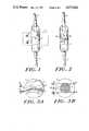
- FIG. 4shows the mirror of the present invention, in another embodiment, incorporated in a clip-on drop monitor 40.
- monitor 40comprises a housing 41 having two opposing portions 42, 43 spaced apart and configured to fit around a drip chamber.
- Resilient clips 44are positioned to receive the drip chamber and hold it centrally aligned between portions 42, 43.
- Housed in portion 42are a light source 6 and detector 7 (not shown).
- Housed in portion 43is mirror 8, which, as shown, is mounted on contoured mirror block 45.
- Block 45is preferably a molded plastic block having a surface 46 on which a reflective tape or coating forming the mirror 8 is attached or formed. Surface 46 is configured to have the focal properties discussed in relation to FIGS.
- a slot 47 or other vertical registration meansmay be provided to assure the proper vertical registration of the drop former of a drip chamber within the housing at the level of mirror 8.
- Signal processing or power circuitrymay also be mounted within the housing, and connected via cable 48 to a programmable control device.
- FIG. 5shows further details of the mirror block 45 of the embodiment of FIG. 4.
- the block 45is a roughly rectangular block having a contoured front face 46 with mirror 8 formed or attached thereon.
- mirror 8has a central region 81 preferably of a width w not much larger than the nominal drop diameter, and flared end portions 82, 83 of somewhat greater width.
- contoured face 46intersects the top face of mirror block 45 along edge 49, which is curved.
- face 46is a portion of surface of revolution chosen so that mirror 8 will focus light at the appropriate region 42 of the monitor to strike the detector.
- Mirror block 45may be hollow, in which case it may serve to house circuit elements for signal processing, or other devices, such as a drop buzzer, discussed below.
- FIG. 6shows a horizontal section along plane VI--VI of the monitor of FIG. 4, showing the placement of the light source 6 and detector 7 in portion 42, opposing the mirror 8 in portion 43. Also shown is a motor M having an eccentric or imbalanced wheel W mounted on its shaft, and placed in the hollow mirror block 45, previously described. Motor M is a miniature rotary electric motor, which because of its imbalanced wheel, is operative when energized to transmit a vigorous vibratory energy to the monitor assembly. Motor M is controlled by a microprocessor based controller to which the drop monitor assembly is attached, the controller being programmed so that upon the failure of the monitor to detect a drop for a predetermined time interval, motor M is energized for several seconds.
- a microprocessor based controllerto which the drop monitor assembly is attached, the controller being programmed so that upon the failure of the monitor to detect a drop for a predetermined time interval, motor M is energized for several seconds.
- the situationmay be caused by droplet accumulation, and the arrangement in a preferred embodiment is energized whenever this situation occurs.
- the vibratormay run continuously.
- the rapidly rotating imbalanced wheelcauses a strong vibration of the entire housing/drip chamber structure, thus clearing any accumulation of droplets from the wall of the drip chamber.
- Such an arrangementserves as a highly effective means for clearing the accumulation because of its efficient transfer of energy to the assembly. It thus replaces the manual finger-flicking commonly used for such purpose.
- the vibrating arrangementserves the further function of emitting an audible signal which may alert the user to possible line blockage or empty reservoir conditions.
- FIG. 7shows a vertical section of the embodiment of FIG. 4, along the plane VII--VII.
- drip chamber 1is held between the source/detector housing 42 and the mirror housing 43.
- Contoured face 46 of the mirror blockis seen to have a curved vertical section, enabling mirror 8 to focus approximately in the region of detector 7.
- Mirror block 45is seen to be hollow and to house motor M with eccentric weight W on its shaft.
- a drip chamber in shapethat includes a specially configured reflective region (i.e., a single reflecting element) or that has multiple reflective faces (analogous to FIG. 3B) for focusing a source light to a predetermined region outside the chamber.
- the narrow band mirrore.g. of FIG. 1
- a suitable maskwhich may, for example, be painted on the chamber
Landscapes
- Health & Medical Sciences (AREA)
- Physics & Mathematics (AREA)
- Engineering & Computer Science (AREA)
- Biomedical Technology (AREA)
- Hematology (AREA)
- Theoretical Computer Science (AREA)
- Vascular Medicine (AREA)
- Anesthesiology (AREA)
- General Physics & Mathematics (AREA)
- Heart & Thoracic Surgery (AREA)
- Fluid Mechanics (AREA)
- Life Sciences & Earth Sciences (AREA)
- Animal Behavior & Ethology (AREA)
- General Health & Medical Sciences (AREA)
- Public Health (AREA)
- Veterinary Medicine (AREA)
- Infusion, Injection, And Reservoir Apparatuses (AREA)
- Investigating Or Analysing Materials By Optical Means (AREA)
- Geophysics And Detection Of Objects (AREA)
Abstract
Description
Claims (12)
Priority Applications (6)
| Application Number | Priority Date | Filing Date | Title |
|---|---|---|---|
| US06/669,108US4673820A (en) | 1984-11-07 | 1984-11-07 | Drop detecting system with focusing mirror element and vibrator |
| EP85905579AEP0198909B1 (en) | 1984-11-07 | 1985-10-29 | Drop detection system with mirror element |
| DE8585905579TDE3583609D1 (en) | 1984-11-07 | 1985-10-29 | DROP DETECTION SYSTEM WITH MIRROR ELEMENT. |
| PCT/US1985/002128WO1986003002A1 (en) | 1984-11-07 | 1985-10-29 | Drop detection system with mirror element |
| JP60504896AJPS62500738A (en) | 1984-11-07 | 1985-10-29 | Drip detection system with reflector |
| CA000494779ACA1245741A (en) | 1984-11-07 | 1985-11-07 | Drop detection system with mirror element |
Applications Claiming Priority (1)
| Application Number | Priority Date | Filing Date | Title |
|---|---|---|---|
| US06/669,108US4673820A (en) | 1984-11-07 | 1984-11-07 | Drop detecting system with focusing mirror element and vibrator |
Publications (1)
| Publication Number | Publication Date |
|---|---|
| US4673820Atrue US4673820A (en) | 1987-06-16 |
Family
ID=24685051
Family Applications (1)
| Application Number | Title | Priority Date | Filing Date |
|---|---|---|---|
| US06/669,108Expired - Fee RelatedUS4673820A (en) | 1984-11-07 | 1984-11-07 | Drop detecting system with focusing mirror element and vibrator |
Country Status (6)
| Country | Link |
|---|---|
| US (1) | US4673820A (en) |
| EP (1) | EP0198909B1 (en) |
| JP (1) | JPS62500738A (en) |
| CA (1) | CA1245741A (en) |
| DE (1) | DE3583609D1 (en) |
| WO (1) | WO1986003002A1 (en) |
Cited By (56)
| Publication number | Priority date | Publication date | Assignee | Title |
|---|---|---|---|---|
| US4857050A (en)* | 1987-09-23 | 1989-08-15 | Fisher Scientific Company | Ratiometric air-in-line detector |
| US5154704A (en)* | 1990-10-31 | 1992-10-13 | Kent Archibald G | IV clamp with tube clip |
| US5266495A (en)* | 1990-03-02 | 1993-11-30 | Cytyc Corporation | Method and apparatus for controlled instrumentation of particles with a filter device |
| US5277927A (en)* | 1992-03-23 | 1994-01-11 | Nordson Corporation | Method of applying primers onto glass elements of vehicles |
| US5370905A (en)* | 1992-03-23 | 1994-12-06 | Nordson Corporation | Method of applying priming coating materials onto glass elements of vehicles |
| US5459569A (en)* | 1993-04-21 | 1995-10-17 | Particle Measuring Systems, Inc. | Nonintrusive modular particle detecting device |
| AU668089B2 (en)* | 1991-04-01 | 1996-04-26 | Covidien Ag | Drop detection method and apparatus |
| US5899597A (en)* | 1993-12-22 | 1999-05-04 | Ricoh Company Ltd. | Toner cartridge with an external reflector for a developer apparatus capable of optically end-detecting |
| US5982289A (en)* | 1998-09-25 | 1999-11-09 | Dowty Aerospace Yakima | Drip counter apparatus |
| US6318190B1 (en) | 1996-11-01 | 2001-11-20 | Cytyc Corporation | Systems for collecting fluid samples having select concentrations of particles |
| US6513900B2 (en)* | 2000-02-23 | 2003-02-04 | Seiko Epson Corporation | Detection of non-operating nozzle by light beam passing through aperture |
| DE102006029899A1 (en)* | 2006-06-29 | 2008-01-03 | Fresenius Medical Care Deutschland Gmbh | Spectroscopic detector and method for the determination of blood and biological markers in liquids |
| US20080147016A1 (en)* | 1997-03-03 | 2008-06-19 | Faries Durward I | Method and Apparatus for Pressure Infusion and Temperature Control of Infused Liquids |
| US7414255B1 (en)* | 2005-03-25 | 2008-08-19 | Amend John R | Drop counter |
| US20080205481A1 (en)* | 2007-02-22 | 2008-08-28 | Faries Durward I | Method and Apparatus for Measurement and Control of Temperature for Infused Liquids |
| US7852465B1 (en) | 2006-11-07 | 2010-12-14 | Fluid Measurement Technologies, Inc. | System for measuring liquid flow rates |
| US7916293B2 (en) | 2007-12-04 | 2011-03-29 | Particle Measuring Systems, Inc. | Non-orthogonal particle detection systems and methods |
| US8226605B2 (en) | 2001-12-17 | 2012-07-24 | Medical Solutions, Inc. | Method and apparatus for heating solutions within intravenous lines to desired temperatures during infusion |
| US8444599B2 (en) | 2005-10-27 | 2013-05-21 | Patented Medical Solutions, Llc | Method and apparatus to indicate prior use of a medical item |
| US8487738B2 (en) | 2006-03-20 | 2013-07-16 | Medical Solutions, Inc. | Method and apparatus for securely storing medical items within a thermal treatment system |
| US8622979B2 (en) | 2010-10-19 | 2014-01-07 | Baxter Healthcare S.A. | Infusion system using optical imager for controlling flow and method thereof |
| US8821011B2 (en) | 1999-03-30 | 2014-09-02 | Medical Solutions, Inc. | Method and apparatus for monitoring temperature of intravenously delivered fluids and other medical items |
| US8845586B2 (en) | 2004-03-09 | 2014-09-30 | Patented Medical Solutions Llc | Method and apparatus for facilitating injection of medication into an intravenous fluid line while maintaining sterility of infused fluids |
| US9119912B2 (en) | 2001-03-12 | 2015-09-01 | Medical Solutions, Inc. | Method and apparatus for controlling pressurized infusion and temperature of infused liquids |
| US9128051B2 (en) | 2010-10-19 | 2015-09-08 | Baxter International Inc. | Optical imaging system for air bubble and empty bag detection in an infusion tube |
| US9144644B2 (en) | 2011-08-02 | 2015-09-29 | Baxter International Inc. | Infusion pump with independently controllable valves and low power operation and methods thereof |
| US9151646B2 (en) | 2011-12-21 | 2015-10-06 | Deka Products Limited Partnership | System, method, and apparatus for monitoring, regulating, or controlling fluid flow |
| USD745661S1 (en) | 2013-11-06 | 2015-12-15 | Deka Products Limited Partnership | Apparatus to control fluid flow through a tube |
| US9211381B2 (en) | 2012-01-20 | 2015-12-15 | Medical Solutions, Inc. | Method and apparatus for controlling temperature of medical liquids |
| USD749206S1 (en) | 2013-11-06 | 2016-02-09 | Deka Products Limited Partnership | Apparatus to control fluid flow through a tube |
| USD751689S1 (en) | 2013-11-06 | 2016-03-15 | Deka Products Limited Partnership | Apparatus to control fluid flow through a tube |
| USD751690S1 (en) | 2013-11-06 | 2016-03-15 | Deka Products Limited Partnership | Apparatus to control fluid flow through a tube |
| USD752209S1 (en) | 2013-11-06 | 2016-03-22 | Deka Products Limited Partnership | Apparatus to control fluid flow through a tube |
| US9372486B2 (en) | 2011-12-21 | 2016-06-21 | Deka Products Limited Partnership | System, method, and apparatus for monitoring, regulating, or controlling fluid flow |
| US9435455B2 (en) | 2011-12-21 | 2016-09-06 | Deka Products Limited Partnership | System, method, and apparatus for monitoring, regulating, or controlling fluid flow |
| US9476825B2 (en) | 2010-10-19 | 2016-10-25 | Baxter International Inc. | Optical imaging system with multiple imaging channel optical sensing |
| US9656029B2 (en) | 2013-02-15 | 2017-05-23 | Medical Solutions, Inc. | Plural medical item warming system and method for warming a plurality of medical items to desired temperatures |
| US9724465B2 (en) | 2011-12-21 | 2017-08-08 | Deka Products Limited Partnership | Flow meter |
| US9737661B2 (en) | 2013-01-23 | 2017-08-22 | Tatsuta Electric Wire & Cable Co., Ltd. | Infusion speed measurement instrument |
| US9746094B2 (en) | 2011-12-21 | 2017-08-29 | Deka Products Limited Partnership | Flow meter having a background pattern with first and second portions |
| US9746093B2 (en) | 2011-12-21 | 2017-08-29 | Deka Products Limited Partnership | Flow meter and related system and apparatus |
| US9759343B2 (en) | 2012-12-21 | 2017-09-12 | Deka Products Limited Partnership | Flow meter using a dynamic background image |
| US10228683B2 (en) | 2011-12-21 | 2019-03-12 | Deka Products Limited Partnership | System, method, and apparatus for monitoring, regulating, or controlling fluid flow |
| CN109939297A (en)* | 2017-12-20 | 2019-06-28 | 美尔敦股份有限公司 | A drip detection device and method |
| USD854145S1 (en) | 2016-05-25 | 2019-07-16 | Deka Products Limited Partnership | Apparatus to control fluid flow through a tube |
| US10429312B2 (en) | 2013-03-14 | 2019-10-01 | Baxter International Inc. | Drip chamber with integrated optics |
| CN110494180A (en)* | 2017-02-01 | 2019-11-22 | 赛诺菲-安万特德国有限公司 | For being attached to the monitoring device of injection device |
| US10488848B2 (en) | 2011-12-21 | 2019-11-26 | Deka Products Limited Partnership | System, method, and apparatus for monitoring, regulating, or controlling fluid flow |
| US20200240826A1 (en)* | 2019-01-28 | 2020-07-30 | Battelle Memorial Institute | Fluid end of life sensors |
| USD905848S1 (en) | 2016-01-28 | 2020-12-22 | Deka Products Limited Partnership | Apparatus to control fluid flow through a tube |
| US10983044B2 (en)* | 2018-06-26 | 2021-04-20 | Arometrix, Inc. | Device, system and method for in-situ optical monitoring and control of extraction and purification of plant materials |
| CN114191653A (en)* | 2021-11-23 | 2022-03-18 | 广东德澳智慧医疗科技有限公司 | Infrared light liquid drop detection device and method |
| USD964563S1 (en) | 2019-07-26 | 2022-09-20 | Deka Products Limited Partnership | Medical flow clamp |
| US11744935B2 (en) | 2016-01-28 | 2023-09-05 | Deka Products Limited Partnership | Apparatus for monitoring, regulating, or controlling fluid flow |
| US11839741B2 (en) | 2019-07-26 | 2023-12-12 | Deka Products Limited Partneship | Apparatus for monitoring, regulating, or controlling fluid flow |
| US12098738B2 (en) | 2011-12-21 | 2024-09-24 | Deka Products Limited Partnership | System, method, and apparatus for clamping |
Families Citing this family (5)
| Publication number | Priority date | Publication date | Assignee | Title |
|---|---|---|---|---|
| US5415641A (en)* | 1991-04-01 | 1995-05-16 | Sherwood Medical Company | Drop detection method and apparatus |
| AU766731B2 (en)* | 1991-04-01 | 2003-10-23 | Covidien Ag | Drop detection method and apparatus |
| WO2020101052A1 (en)* | 2018-11-13 | 2020-05-22 | 주식회사 신성티케이 | Device for monitoring intravenous fluid |
| CN109752291A (en)* | 2019-02-28 | 2019-05-14 | 西北工业大学 | A trigger device for monitoring the falling process of tiny droplets |
| WO2024200213A1 (en)* | 2023-03-24 | 2024-10-03 | droptical GmbH | Device for detecting at least one drop |
Citations (5)
| Publication number | Priority date | Publication date | Assignee | Title |
|---|---|---|---|---|
| US3563090A (en)* | 1968-09-18 | 1971-02-16 | Basil V Deltour | Drop monitor |
| US3989381A (en)* | 1975-05-05 | 1976-11-02 | Coulter Electronics, Inc. | Optical chamber with spherical reflective portion and apparatus employing same |
| US4261388A (en)* | 1978-05-19 | 1981-04-14 | Frenshore Ltd. | Drop rate controller |
| US4496351A (en)* | 1982-04-05 | 1985-01-29 | Ipco Corporation | Infusion monitor |
| US4533350A (en)* | 1983-05-10 | 1985-08-06 | Anatros Corporation | Parenteral solution delivery control system |
Family Cites Families (2)
| Publication number | Priority date | Publication date | Assignee | Title |
|---|---|---|---|---|
| US4273443A (en)* | 1979-11-21 | 1981-06-16 | Coulter Electronics, Inc. | Method and apparatus for measurement of reradiation in particle flow cell systems |
| US4422761A (en)* | 1981-09-28 | 1983-12-27 | Frommer Joseph C | Photo-electric particle sensing system |
- 1984
- 1984-11-07USUS06/669,108patent/US4673820A/ennot_activeExpired - Fee Related
- 1985
- 1985-10-29WOPCT/US1985/002128patent/WO1986003002A1/enactiveIP Right Grant
- 1985-10-29JPJP60504896Apatent/JPS62500738A/enactivePending
- 1985-10-29EPEP85905579Apatent/EP0198909B1/ennot_activeExpired
- 1985-10-29DEDE8585905579Tpatent/DE3583609D1/ennot_activeExpired - Lifetime
- 1985-11-07CACA000494779Apatent/CA1245741A/ennot_activeExpired
Patent Citations (5)
| Publication number | Priority date | Publication date | Assignee | Title |
|---|---|---|---|---|
| US3563090A (en)* | 1968-09-18 | 1971-02-16 | Basil V Deltour | Drop monitor |
| US3989381A (en)* | 1975-05-05 | 1976-11-02 | Coulter Electronics, Inc. | Optical chamber with spherical reflective portion and apparatus employing same |
| US4261388A (en)* | 1978-05-19 | 1981-04-14 | Frenshore Ltd. | Drop rate controller |
| US4496351A (en)* | 1982-04-05 | 1985-01-29 | Ipco Corporation | Infusion monitor |
| US4533350A (en)* | 1983-05-10 | 1985-08-06 | Anatros Corporation | Parenteral solution delivery control system |
Cited By (121)
| Publication number | Priority date | Publication date | Assignee | Title |
|---|---|---|---|---|
| US4857050A (en)* | 1987-09-23 | 1989-08-15 | Fisher Scientific Company | Ratiometric air-in-line detector |
| US6225125B1 (en) | 1990-03-02 | 2001-05-01 | Cytyc Corporation | Method and apparatus for controlled instrumentation of particles with a filter device |
| US6010909A (en)* | 1990-03-02 | 2000-01-04 | Cytyc Corporation | Method and apparatus for controlled instrumentation of particles with a filter device |
| US5266495A (en)* | 1990-03-02 | 1993-11-30 | Cytyc Corporation | Method and apparatus for controlled instrumentation of particles with a filter device |
| US5154704A (en)* | 1990-10-31 | 1992-10-13 | Kent Archibald G | IV clamp with tube clip |
| AU668089B2 (en)* | 1991-04-01 | 1996-04-26 | Covidien Ag | Drop detection method and apparatus |
| US5277927A (en)* | 1992-03-23 | 1994-01-11 | Nordson Corporation | Method of applying primers onto glass elements of vehicles |
| US5370905A (en)* | 1992-03-23 | 1994-12-06 | Nordson Corporation | Method of applying priming coating materials onto glass elements of vehicles |
| US5459569A (en)* | 1993-04-21 | 1995-10-17 | Particle Measuring Systems, Inc. | Nonintrusive modular particle detecting device |
| US5899597A (en)* | 1993-12-22 | 1999-05-04 | Ricoh Company Ltd. | Toner cartridge with an external reflector for a developer apparatus capable of optically end-detecting |
| US6318190B1 (en) | 1996-11-01 | 2001-11-20 | Cytyc Corporation | Systems for collecting fluid samples having select concentrations of particles |
| US6634244B2 (en) | 1996-11-01 | 2003-10-21 | Cytyc Corporation | Methods for collecting fluid samples having select concentrations of particles |
| US20040219073A1 (en)* | 1996-11-01 | 2004-11-04 | Cytyc Corporation | Systems and methods for generating fluid samples having select concentration of particles |
| US20100168671A1 (en)* | 1997-03-03 | 2010-07-01 | Faries Jr Durward I | Method and Apparatus for Pressure Infusion and Temperature Control of Infused Liquids |
| US20080147016A1 (en)* | 1997-03-03 | 2008-06-19 | Faries Durward I | Method and Apparatus for Pressure Infusion and Temperature Control of Infused Liquids |
| US8920387B2 (en)* | 1997-03-03 | 2014-12-30 | Medical Solutions, Inc. | Method and apparatus for pressure infusion and temperature control of infused liquids |
| US8313462B2 (en) | 1997-03-03 | 2012-11-20 | Medical Solutions, Inc. | Method and apparatus for pressure infusion and temperature control of infused liquids |
| US7942851B2 (en) | 1997-03-03 | 2011-05-17 | Medical Solutions, Inc. | Method and apparatus for pressure infusion and temperature control of infused liquids |
| US5982289A (en)* | 1998-09-25 | 1999-11-09 | Dowty Aerospace Yakima | Drip counter apparatus |
| US8821011B2 (en) | 1999-03-30 | 2014-09-02 | Medical Solutions, Inc. | Method and apparatus for monitoring temperature of intravenously delivered fluids and other medical items |
| US6513900B2 (en)* | 2000-02-23 | 2003-02-04 | Seiko Epson Corporation | Detection of non-operating nozzle by light beam passing through aperture |
| US9119912B2 (en) | 2001-03-12 | 2015-09-01 | Medical Solutions, Inc. | Method and apparatus for controlling pressurized infusion and temperature of infused liquids |
| US8920372B2 (en) | 2001-12-17 | 2014-12-30 | Medical Solutions, Inc. | Method and apparatus for heating solutions within intravenous lines to desired temperatures during infusion |
| US8226605B2 (en) | 2001-12-17 | 2012-07-24 | Medical Solutions, Inc. | Method and apparatus for heating solutions within intravenous lines to desired temperatures during infusion |
| US9492624B2 (en) | 2001-12-17 | 2016-11-15 | Medical Solutions, Inc. | Method and apparatus for heating solutions within intravenous lines to desired temperatures during infusion |
| US8845586B2 (en) | 2004-03-09 | 2014-09-30 | Patented Medical Solutions Llc | Method and apparatus for facilitating injection of medication into an intravenous fluid line while maintaining sterility of infused fluids |
| US7414255B1 (en)* | 2005-03-25 | 2008-08-19 | Amend John R | Drop counter |
| US8636691B2 (en) | 2005-10-27 | 2014-01-28 | Patented Medical Solutions, Llc | Method and apparatus to indicate prior use of a medical item |
| US8444599B2 (en) | 2005-10-27 | 2013-05-21 | Patented Medical Solutions, Llc | Method and apparatus to indicate prior use of a medical item |
| US8487738B2 (en) | 2006-03-20 | 2013-07-16 | Medical Solutions, Inc. | Method and apparatus for securely storing medical items within a thermal treatment system |
| US8054452B2 (en) | 2006-06-29 | 2011-11-08 | Fresenius Medical Care Deutschland Gmbh | Spectroscopic detector and method for determining the presence of blood and biological marker substances in liquids |
| DE102006029899A1 (en)* | 2006-06-29 | 2008-01-03 | Fresenius Medical Care Deutschland Gmbh | Spectroscopic detector and method for the determination of blood and biological markers in liquids |
| US20090279071A1 (en)* | 2006-06-29 | 2009-11-12 | Fresenius Medical Care Deutschland Gmbh | Spectroscopic detector and method for determining the presence of blood and biological marker substances in liquids |
| US8269953B2 (en) | 2006-06-29 | 2012-09-18 | Fresenius Medical Care Deutschland Gmbh | Spectroscopic detector and method for determining the presence of blood and biological marker substances in liquids |
| DE102006029899B4 (en)* | 2006-06-29 | 2009-06-04 | Fresenius Medical Care Deutschland Gmbh | Spectroscopic detector and method for the determination of blood and biological markers in liquids |
| EP2032967B1 (en) | 2006-06-29 | 2017-08-09 | Fresenius Medical Care Deutschland GmbH | Spectroscopic detector and method for determining the presence of blood and biological marker substances in liquids |
| US7852465B1 (en) | 2006-11-07 | 2010-12-14 | Fluid Measurement Technologies, Inc. | System for measuring liquid flow rates |
| US8226293B2 (en) | 2007-02-22 | 2012-07-24 | Medical Solutions, Inc. | Method and apparatus for measurement and control of temperature for infused liquids |
| US20080205481A1 (en)* | 2007-02-22 | 2008-08-28 | Faries Durward I | Method and Apparatus for Measurement and Control of Temperature for Infused Liquids |
| US20110155927A1 (en)* | 2007-12-04 | 2011-06-30 | Particle Measuring Systems, Inc. | Non-Orthogonal Particle Detection Systems and Methods |
| US8427642B2 (en) | 2007-12-04 | 2013-04-23 | Particle Measuring Systems, Inc. | Two-dimensional optical imaging methods and systems for particle detection |
| US8174697B2 (en) | 2007-12-04 | 2012-05-08 | Particle Measuring Systems, Inc. | Non-orthogonal particle detection systems and methods |
| US8154724B2 (en) | 2007-12-04 | 2012-04-10 | Particle Measuring Systems, Inc. | Two-dimensional optical imaging methods and systems for particle detection |
| US8027035B2 (en) | 2007-12-04 | 2011-09-27 | Particle Measuring Systems, Inc. | Non-orthogonal particle detection systems and methods |
| US7916293B2 (en) | 2007-12-04 | 2011-03-29 | Particle Measuring Systems, Inc. | Non-orthogonal particle detection systems and methods |
| US11529465B2 (en) | 2010-10-19 | 2022-12-20 | Baxter International Inc. | Infusion system using optical imager for controlling flow and method thereof |
| US9476825B2 (en) | 2010-10-19 | 2016-10-25 | Baxter International Inc. | Optical imaging system with multiple imaging channel optical sensing |
| US11571512B2 (en) | 2010-10-19 | 2023-02-07 | Baxter International Inc. | Infusion system using optical imager for controlling flow and method thereof |
| US8622979B2 (en) | 2010-10-19 | 2014-01-07 | Baxter Healthcare S.A. | Infusion system using optical imager for controlling flow and method thereof |
| US9128051B2 (en) | 2010-10-19 | 2015-09-08 | Baxter International Inc. | Optical imaging system for air bubble and empty bag detection in an infusion tube |
| US9603999B2 (en) | 2010-10-19 | 2017-03-28 | Baxter International Inc. | Infusion system using optical imager for controlling flow and method thereof |
| US10406284B2 (en) | 2010-10-19 | 2019-09-10 | Baxter International Inc. | Optical imaging system with multiple imaging channel optical sensing |
| US10226574B2 (en) | 2010-10-19 | 2019-03-12 | Baxter International Inc. | Infusion system using optical imager for controlling flow and method thereof |
| US10220140B2 (en) | 2010-10-19 | 2019-03-05 | Baxter International Inc. | Infusion system using optical imager for controlling flow and method thereof |
| US11583630B2 (en) | 2010-10-19 | 2023-02-21 | Baxter International Inc. | Optical imaging system with multiple imaging channel optical sensing |
| US10006454B2 (en) | 2011-08-02 | 2018-06-26 | Baxter International Inc. | Infusion pump with independently controllable valves and low power operation and methods thereof |
| US9144644B2 (en) | 2011-08-02 | 2015-09-29 | Baxter International Inc. | Infusion pump with independently controllable valves and low power operation and methods thereof |
| US10851773B2 (en) | 2011-08-02 | 2020-12-01 | Baxter International Inc. | Infusion pump with independently controllable valves and low power operation and methods thereof |
| US10865786B2 (en) | 2011-08-02 | 2020-12-15 | Baxter International Inc. | Infusion pump with independently controllable valves and low power operation and methods thereof |
| US9724467B2 (en) | 2011-12-21 | 2017-08-08 | Deka Products Limited Partnership | Flow meter |
| US10718445B2 (en) | 2011-12-21 | 2020-07-21 | Deka Products Limited Partnership | Flow meter having a valve |
| US9724466B2 (en) | 2011-12-21 | 2017-08-08 | Deka Products Limited Partnership | Flow meter |
| US12098738B2 (en) | 2011-12-21 | 2024-09-24 | Deka Products Limited Partnership | System, method, and apparatus for clamping |
| US12100507B2 (en) | 2011-12-21 | 2024-09-24 | Deka Products Limited Partnership | System, method, and apparatus for monitoring, regulating, or controlling fluid flow |
| US9746094B2 (en) | 2011-12-21 | 2017-08-29 | Deka Products Limited Partnership | Flow meter having a background pattern with first and second portions |
| US9746093B2 (en) | 2011-12-21 | 2017-08-29 | Deka Products Limited Partnership | Flow meter and related system and apparatus |
| US11793928B2 (en) | 2011-12-21 | 2023-10-24 | Deka Products Limited Partnership | Flow meter and related method |
| US11738143B2 (en) | 2011-12-21 | 2023-08-29 | Deka Products Limited Partnership | Flow meier having a valve |
| US9772044B2 (en) | 2011-12-21 | 2017-09-26 | Deka Products Limited Partnership | Flow metering using a difference image for liquid parameter estimation |
| US9151646B2 (en) | 2011-12-21 | 2015-10-06 | Deka Products Limited Partnership | System, method, and apparatus for monitoring, regulating, or controlling fluid flow |
| US11574407B2 (en) | 2011-12-21 | 2023-02-07 | Deka Products Limited Partnership | System, method, and apparatus for monitoring, regulating, or controlling fluid flow |
| US9856990B2 (en) | 2011-12-21 | 2018-01-02 | Deka Products Limited Partnership | Flow metering using a difference image for liquid parameter estimation |
| US11449037B2 (en) | 2011-12-21 | 2022-09-20 | Deka Products Limited Partnership | System, method, and apparatus for monitoring, regulating, or controlling fluid flow |
| US11339887B2 (en) | 2011-12-21 | 2022-05-24 | Deka Products Limited Partnership | Flow meter and related method |
| US10894638B2 (en) | 2011-12-21 | 2021-01-19 | Deka Products Limited Partnership | System, method, and apparatus for monitoring, regulating, or controlling fluid flow |
| US9976665B2 (en) | 2011-12-21 | 2018-05-22 | Deka Products Limited Partnership | Flow meter |
| US9435455B2 (en) | 2011-12-21 | 2016-09-06 | Deka Products Limited Partnership | System, method, and apparatus for monitoring, regulating, or controlling fluid flow |
| US10088346B2 (en) | 2011-12-21 | 2018-10-02 | Deka Products Limited Partnership | System, method, and apparatus for monitoring, regulating, or controlling fluid flow |
| US10113660B2 (en) | 2011-12-21 | 2018-10-30 | Deka Products Limited Partnership | Flow meter |
| US9372486B2 (en) | 2011-12-21 | 2016-06-21 | Deka Products Limited Partnership | System, method, and apparatus for monitoring, regulating, or controlling fluid flow |
| US10228683B2 (en) | 2011-12-21 | 2019-03-12 | Deka Products Limited Partnership | System, method, and apparatus for monitoring, regulating, or controlling fluid flow |
| US10876868B2 (en) | 2011-12-21 | 2020-12-29 | Deka Products Limited Partnership | System, method, and apparatus for monitoring, regulating, or controlling fluid flow |
| US10844970B2 (en) | 2011-12-21 | 2020-11-24 | Deka Products Limited Partnership | Flow meter |
| US10739759B2 (en) | 2011-12-21 | 2020-08-11 | Deka Products Limited Partnership | System, method, and apparatus for monitoring, regulating, or controlling fluid flow |
| US9724465B2 (en) | 2011-12-21 | 2017-08-08 | Deka Products Limited Partnership | Flow meter |
| US10488848B2 (en) | 2011-12-21 | 2019-11-26 | Deka Products Limited Partnership | System, method, and apparatus for monitoring, regulating, or controlling fluid flow |
| US10436342B2 (en) | 2011-12-21 | 2019-10-08 | Deka Products Limited Partnership | Flow meter and related method |
| US9764100B2 (en) | 2012-01-20 | 2017-09-19 | Medical Solutions, Inc. | Method and apparatus for controlling temperature of medical liquids |
| US9211381B2 (en) | 2012-01-20 | 2015-12-15 | Medical Solutions, Inc. | Method and apparatus for controlling temperature of medical liquids |
| US9759343B2 (en) | 2012-12-21 | 2017-09-12 | Deka Products Limited Partnership | Flow meter using a dynamic background image |
| US9737661B2 (en) | 2013-01-23 | 2017-08-22 | Tatsuta Electric Wire & Cable Co., Ltd. | Infusion speed measurement instrument |
| US9656029B2 (en) | 2013-02-15 | 2017-05-23 | Medical Solutions, Inc. | Plural medical item warming system and method for warming a plurality of medical items to desired temperatures |
| US11255795B2 (en) | 2013-03-14 | 2022-02-22 | Baxter International Inc. | Drip chamber with integrated optics |
| US10429312B2 (en) | 2013-03-14 | 2019-10-01 | Baxter International Inc. | Drip chamber with integrated optics |
| USD745661S1 (en) | 2013-11-06 | 2015-12-15 | Deka Products Limited Partnership | Apparatus to control fluid flow through a tube |
| USD749206S1 (en) | 2013-11-06 | 2016-02-09 | Deka Products Limited Partnership | Apparatus to control fluid flow through a tube |
| USD752209S1 (en) | 2013-11-06 | 2016-03-22 | Deka Products Limited Partnership | Apparatus to control fluid flow through a tube |
| USD816829S1 (en) | 2013-11-06 | 2018-05-01 | Deka Products Limited Partnership | Apparatus to control fluid flow through a tube |
| USD751690S1 (en) | 2013-11-06 | 2016-03-15 | Deka Products Limited Partnership | Apparatus to control fluid flow through a tube |
| USD751689S1 (en) | 2013-11-06 | 2016-03-15 | Deka Products Limited Partnership | Apparatus to control fluid flow through a tube |
| USD799025S1 (en) | 2013-11-06 | 2017-10-03 | Deka Products Limited Partnership | Apparatus to control fluid flow through a tube |
| USD815730S1 (en) | 2013-11-06 | 2018-04-17 | Deka Products Limited Partnership | Apparatus to control fluid flow through a tube |
| USD802118S1 (en) | 2013-11-06 | 2017-11-07 | Deka Products Limited Partnership | Apparatus to control fluid flow through a tube |
| USD813376S1 (en) | 2013-11-06 | 2018-03-20 | Deka Products Limited Partnership | Apparatus to control fluid flow through a tube |
| USD905848S1 (en) | 2016-01-28 | 2020-12-22 | Deka Products Limited Partnership | Apparatus to control fluid flow through a tube |
| US11744935B2 (en) | 2016-01-28 | 2023-09-05 | Deka Products Limited Partnership | Apparatus for monitoring, regulating, or controlling fluid flow |
| USD943736S1 (en) | 2016-01-28 | 2022-02-15 | Deka Products Limited Partnership | Apparatus to control fluid flow through a tube |
| USD972125S1 (en) | 2016-05-25 | 2022-12-06 | Deka Products Limited Partnership | Apparatus to control fluid flow through a tube |
| USD972718S1 (en) | 2016-05-25 | 2022-12-13 | Deka Products Limited Partnership | Apparatus to control fluid flow through a tube |
| USD1060608S1 (en) | 2016-05-25 | 2025-02-04 | Deka Products Limited Partnership | Device to control fluid flow through a tube |
| USD860437S1 (en) | 2016-05-25 | 2019-09-17 | Deka Products Limited Partnership | Apparatus to control fluid flow through a tube |
| USD854145S1 (en) | 2016-05-25 | 2019-07-16 | Deka Products Limited Partnership | Apparatus to control fluid flow through a tube |
| US11141532B2 (en)* | 2017-02-01 | 2021-10-12 | Sanofi-Aventis Deutschland Gmbh | Monitoring device for attachment to an injection device |
| CN110494180A (en)* | 2017-02-01 | 2019-11-22 | 赛诺菲-安万特德国有限公司 | For being attached to the monitoring device of injection device |
| CN109939297A (en)* | 2017-12-20 | 2019-06-28 | 美尔敦股份有限公司 | A drip detection device and method |
| US10983044B2 (en)* | 2018-06-26 | 2021-04-20 | Arometrix, Inc. | Device, system and method for in-situ optical monitoring and control of extraction and purification of plant materials |
| US20200240826A1 (en)* | 2019-01-28 | 2020-07-30 | Battelle Memorial Institute | Fluid end of life sensors |
| US11839741B2 (en) | 2019-07-26 | 2023-12-12 | Deka Products Limited Partneship | Apparatus for monitoring, regulating, or controlling fluid flow |
| USD964563S1 (en) | 2019-07-26 | 2022-09-20 | Deka Products Limited Partnership | Medical flow clamp |
| CN114191653A (en)* | 2021-11-23 | 2022-03-18 | 广东德澳智慧医疗科技有限公司 | Infrared light liquid drop detection device and method |
| CN114191653B (en)* | 2021-11-23 | 2023-09-08 | 广东德澳智慧医疗科技有限公司 | Infrared light liquid drop detection device and method |
Also Published As
| Publication number | Publication date |
|---|---|
| DE3583609D1 (en) | 1991-08-29 |
| EP0198909A4 (en) | 1989-06-21 |
| WO1986003002A1 (en) | 1986-05-22 |
| EP0198909A1 (en) | 1986-10-29 |
| JPS62500738A (en) | 1987-03-26 |
| EP0198909B1 (en) | 1991-07-24 |
| CA1245741A (en) | 1988-11-29 |
Similar Documents
| Publication | Publication Date | Title |
|---|---|---|
| US4673820A (en) | Drop detecting system with focusing mirror element and vibrator | |
| CA2102424C (en) | Drop detection method and apparatus | |
| CA1252682A (en) | Parenteral solution delivery control system | |
| EP0121848B1 (en) | Apparatus for detecting bubbles in a liquid | |
| US4680977A (en) | Optical flow sensor | |
| US4720636A (en) | Drop detecting system which operates under different ambient light conditions | |
| US5415641A (en) | Drop detection method and apparatus | |
| JP2510386B2 (en) | A method of extrapolating the volume of a free-falling drop | |
| US6414747B1 (en) | Infrared photodetector apparatus for measuring projectile velocity | |
| TW501078B (en) | Stray light detector | |
| JPH01314573A (en) | Apparatus for detecting presence of air in piping | |
| CA1232154A (en) | Fluid flowmeter | |
| JPH08233736A (en) | Microparticle detection sensor | |
| JP2017503616A (en) | Fluorescent light sensor for detecting infusion pump cassettes | |
| CN104574773A (en) | Smoke detector | |
| CN218332821U (en) | Housing for a detection unit for optically detecting smoke particles, smoke detector, smoke alarm system and fire protection installation | |
| EP0094653A1 (en) | Passive Infrared Intrusion Detector | |
| EP0094659A1 (en) | Passive infrared intrusion detector | |
| EP0125122A2 (en) | Parenteral solution delivery system | |
| AU766731B2 (en) | Drop detection method and apparatus | |
| JP2581838B2 (en) | Light scattering particle detection sensor | |
| JPH0642180Y2 (en) | Liquid level detector | |
| JPS5852517Y2 (en) | photoelectric smoke detector | |
| JPH04322397A (en) | Smoke sensor with confirmation lamp | |
| JPH0794996B2 (en) | Fluid flow rate sensing device |
Legal Events
| Date | Code | Title | Description |
|---|---|---|---|
| AS | Assignment | Owner name:BAXTER TRAVENOL LABORATORIES, INC., ONE BAXTER PAR Free format text:ASSIGNMENT OF ASSIGNORS INTEREST.;ASSIGNOR:KAMEN, DEAN L.;REEL/FRAME:004387/0161 Effective date:19850412 | |
| FEPP | Fee payment procedure | Free format text:PAYOR NUMBER ASSIGNED (ORIGINAL EVENT CODE: ASPN); ENTITY STATUS OF PATENT OWNER: LARGE ENTITY | |
| AS | Assignment | Owner name:KAMEN, DEAN L., NEW HAMPSHIRE Free format text:ASSIGNMENT OF ASSIGNORS INTEREST.;ASSIGNOR:BAXTER INTERNATIONAL, INC.;REEL/FRAME:005251/0439 Effective date:19900226 | |
| AS | Assignment | Owner name:KAMEN, DEAN L., NEW HAMPSHIRE Free format text:ASSIGNMENT OF ASSIGNORS INTEREST.;ASSIGNOR:BAXTER INTERNATIONAL, INC.;REEL/FRAME:005249/0478 Effective date:19900305 | |
| AS | Assignment | Owner name:DEKA PRODUCTS LIMITED PARTNERSHIP, A LIMITED PART Free format text:ASSIGNMENT OF ASSIGNORS INTEREST.;ASSIGNOR:KAMEN, DEAN L.;REEL/FRAME:005268/0776 Effective date:19900326 | |
| AS | Assignment | Owner name:GENERAL ELECTRIC CAPITAL CORPORATION, A CORP. OF N Free format text:SECURITY INTEREST;ASSIGNOR:IMED CORPORATION, A CORP. OF DE;REEL/FRAME:005281/0682 Effective date:19900402 | |
| FPAY | Fee payment | Year of fee payment:4 | |
| REMI | Maintenance fee reminder mailed | ||
| LAPS | Lapse for failure to pay maintenance fees | ||
| FP | Lapsed due to failure to pay maintenance fee | Effective date:19950621 | |
| STCH | Information on status: patent discontinuation | Free format text:PATENT EXPIRED DUE TO NONPAYMENT OF MAINTENANCE FEES UNDER 37 CFR 1.362 |