US4673390A - Multiple solution IV system - Google Patents
Multiple solution IV systemDownload PDFInfo
- Publication number
- US4673390A US4673390AUS06/676,009US67600984AUS4673390AUS 4673390 AUS4673390 AUS 4673390AUS 67600984 AUS67600984 AUS 67600984AUS 4673390 AUS4673390 AUS 4673390A
- Authority
- US
- United States
- Prior art keywords
- valve
- fluid
- control device
- tube
- tubing
- Prior art date
- Legal status (The legal status is an assumption and is not a legal conclusion. Google has not performed a legal analysis and makes no representation as to the accuracy of the status listed.)
- Expired - Fee Related
Links
Images


Classifications
- A—HUMAN NECESSITIES
- A61—MEDICAL OR VETERINARY SCIENCE; HYGIENE
- A61M—DEVICES FOR INTRODUCING MEDIA INTO, OR ONTO, THE BODY; DEVICES FOR TRANSDUCING BODY MEDIA OR FOR TAKING MEDIA FROM THE BODY; DEVICES FOR PRODUCING OR ENDING SLEEP OR STUPOR
- A61M5/00—Devices for bringing media into the body in a subcutaneous, intra-vascular or intramuscular way; Accessories therefor, e.g. filling or cleaning devices, arm-rests
- A61M5/14—Infusion devices, e.g. infusing by gravity; Blood infusion; Accessories therefor
- A61M5/168—Means for controlling media flow to the body or for metering media to the body, e.g. drip meters, counters ; Monitoring media flow to the body
- A61M5/16804—Flow controllers
- A61M5/16827—Flow controllers controlling delivery of multiple fluids, e.g. sequencing, mixing or via separate flow-paths
- Y—GENERAL TAGGING OF NEW TECHNOLOGICAL DEVELOPMENTS; GENERAL TAGGING OF CROSS-SECTIONAL TECHNOLOGIES SPANNING OVER SEVERAL SECTIONS OF THE IPC; TECHNICAL SUBJECTS COVERED BY FORMER USPC CROSS-REFERENCE ART COLLECTIONS [XRACs] AND DIGESTS
- Y10—TECHNICAL SUBJECTS COVERED BY FORMER USPC
- Y10S—TECHNICAL SUBJECTS COVERED BY FORMER USPC CROSS-REFERENCE ART COLLECTIONS [XRACs] AND DIGESTS
- Y10S128/00—Surgery
- Y10S128/13—Infusion monitoring
- Y—GENERAL TAGGING OF NEW TECHNOLOGICAL DEVELOPMENTS; GENERAL TAGGING OF CROSS-SECTIONAL TECHNOLOGIES SPANNING OVER SEVERAL SECTIONS OF THE IPC; TECHNICAL SUBJECTS COVERED BY FORMER USPC CROSS-REFERENCE ART COLLECTIONS [XRACs] AND DIGESTS
- Y10—TECHNICAL SUBJECTS COVERED BY FORMER USPC
- Y10T—TECHNICAL SUBJECTS COVERED BY FORMER US CLASSIFICATION
- Y10T137/00—Fluid handling
- Y10T137/8593—Systems
- Y10T137/87153—Plural noncommunicating flow paths
- Y10T137/87161—With common valve operator
Definitions
- the present inventionrelates to administration of intravenous (IV) fluid.
- the present inventionis an IV administration system which supplies multiple IV solutions or medications at predetermined intervals to a patient.
- the present inventionis an improved IV administration system which has a valve which is suspended from and which acts on flexible tubing between the inlet of an IV control device (such as an IV pump or controller) and a plurality of sources of different IV fluids.
- the valveoperates in response to a valve control signal by constricting all but one tube to selectively connect one of the sources to the inlet of the IV pump.
- control means located with the IV control deviceprovides the valve control signal to the valve means after a predetermined volume of one of the IV fluids is pumped by the IV control device.
- the control meanscontrols operation of the valve means to switch from one source to another when the predetermined volume of IV fluid from the one source has been pumped.
- the present inventiontherefore, all of the medication for a day or more may be contained in one large bag, as opposed to smaller secondary bags that run dry after each delivery of secondary medication. Since the cost of large versus small bags is essentially the same, the system of the present invention achieves significant cost savings by reducing the number of bags which are used, and by reducing the number of times that the medical personnel must change bags.
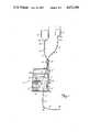
- FIG. 1is a partially schematic diagram of a preferred embodiment of the IV administration system of the present invention.
- FIG. 2is a front view of the IV pump of FIG. 1.
- FIG. 3is an electrical block diagram of the system of FIG. 1.
- FIG. 4is a front view of a first preferred embodiment of the sequence valve of the system of FIG. 1.
- FIG. 5is a front view of the sequence valve of FIG. 4 with the front cover removed.
- FIG. 6is a sectional view along section 6--6 of FIG. 5.
- FIG. 7is a top view of the valve of FIG. 4.
- FIG. 8is a front view of a second preferred embodiment of the sequence valve of the system of FIG. 1.
- FIGS. 9 and 10are partial left and right side views of the sequence valve of FIG. 8.
- FIG. 11is a top view of the sequence valve of FIG. 8 with the tube retainer pivoted to its open position.
- FIG. 12is an electrical schematic diagram of the sequence valve of FIG. 8.
- IV administration system 10includes IV pump 12, which pumps fluid from primary solution bag 14 or secondary (or piggyback) solution bag 16, to a patient (not shown).
- Sequence valve 18is connected between bags 14 and 16 and pump 12 to select one of the bags 14 and 16 for connection to pump 12.
- pump 12is an IV pump such as the AVI GUARDIAN 400 pump manufactured by applicant's assignee AVI, inc.
- Pumps of this general type(which are described in U.S. Pat. No. 4,236,880) use a disposable multiple rolling diaphragm pumping chamber 20 which is inserted into pump 12.
- Pumping chamber 20has an inlet tubing 22 connected at its inlet end, and an outlet tubing 24 at its outlet end.
- a drive mechanism within pump 12causes relative movement of two of the rolling diaphragms of pumping chamber 20 and the operation of two valves to cause fluid to be pumped from inlet tubing 22 through pumping chamber 20 and out through outlet tubing 24 to the patient.
- disposable multiple rolling diaphragm pumping chamber 20inlet tubing 22 and outlet tubing 24 form a part of a disposable IV administration set which also includes primary spike 26, primary drip chamber 28, primary tubing 30, proximal Y connector 32, primary roller clamp 34, secondary spike 36, secondary drip chamber 38, secondary tubing 40, secondary roller clamp 42, distal Y connector 44, distal tubing 46, needle 48, and distal roller clamp 50.
- Primary spike 26is inserted into the lower end of primary bag 14, and is connected to the upper end of primary drip chamber 28.
- the lower end of primary drip chamber 28is connected by primary tubing 30 to one leg of proximal Y connector 32.
- secondary spike 36is inserted into the lower end of secondary bag 16 and is connected to the upper end of secondary drip chamber 38.
- the lower end of secondary drip chamber 38is connected through secondary tubing 40 to the second leg of proximal Y connector 32.
- the third leg of Y connector 32is connected to inlet tubing 22.
- sequence valve 18is a light-weight, solenoid actuated device which initially pinches off primary tubing 30 to prevent flow from primary bag 14 while permitting flow from secondary bag 16 to pumping chamber 20.
- sequence valve 18switches so that secondary tubing 40 is pinched off and primary tubing 30 is unobstructed.
- secondary tubing 40is unobstructed and primary tubing 30 is pinched off, secondary (piggyback) bag 16 is connected to inlet tubing 22, and pump 12 pumps the secondary medication from piggyback bag 16 to the patient.
- secondary tubing 40is pinched off and primary tubing 30 is unobstructed, the primary solution is pumped from the primary bag 14 to the patient by IV pump 12.
- outlet tubing 24is connected through distal Y connector 44 to distal tubing 46.
- needle 48At the end of distal tubing 46 is needle 48, which is inserted into a vein of the patient.
- Distal Y connector 44has another leg which is normally closed, but which allows the insertion of a syringe needle to introduce medication directly into distal tubing 46 as fluid is being pumped to the patient.
- Roller clamps 34, 42 and 50are used by medical personnel during the installation of the IV administration set into pump 12, during initial set-up, and during removal of the IV administration set.
- FIG. 2shows a front view of pump 12.
- Pump 12includes a housing 54 which contains the electrical control circuitry and the mechanical portions of the pump which interact with disposable pumping chamber 20. Pump 12 is supported on an IV stand or pole (not shown) by pole clamp 56.
- Door 58covers a receptacle into which disposable pumping chamber 20 is inserted. In the embodiment shown in FIG. 2, the opening of door 58 requires operation of the three separate devices: load control handle 60, door lock 62, and door latch 64.
- load control handle 60load control handle 60
- door lock 62door lock 62
- door latch 64During normal operation, when the IV administration set is installed with pumping chamber 20 within the receptacle of pump 12, door 58 is closed as shown in FIG. 2.
- control panel 66In the lower left corner of the front of pump 12 is control panel 66, which includes a keyboard formed by numerical key pads ("0" through “9"), operate key pad (OPR) 68, standby key pad (STBY) 70, PRIMARY key pad 72, PIGGYBACK key pad 74, RATE key pad 76, volume limit (LIMIT) key pad 78, and volume infused clear (CLEAR) key pad 80.
- Control panel 66also includes three digital displays: rate display 82, volume limit display 84, and volume infused display 86.
- Pump 12also includes indicator panel 88, (which provides visual indication of different error or alarm conditions), and audio alarm annunciator 90.
- FIG. 3is an electrical block diagram of pump 12 and sequence valve 18, which are connected together by multiconductor able 52 and connector 92 Sequence valve 18 receives a valve control signal from pump 12, and provides a valve state signal, which indicates which fluid line (primary tubing 30 or secondary tubing 40) is occluded.
- Pump control 94receives input signals from control panel 66, from sensors 96 (which sense various operating conditions or parameters such as output pressure, air bubbles in the IV administration set, empty bags and opening of door 58), and from sequence valve 18. Pump control 94 provides outputs to displays 82, 84 and 86 of control panel 66, indicator panel 88, audio annunciator 90 and to pump drive motor 98. In addition, when sequence valve 18 is connected to pump 12 and a piggyback operation has been selected, pump control 94 provides the valve control signal to sequence valve 18.
- Control panel 66allows the medical personnel to "set up” an IV administration schedule so that predetermined volumes of the primary and secondary solutions are delivered at predetermined rates.
- Pump control 94controls the operation of both sequence valve 18 and pump drive motor 98, so that it controls both the particular solution being pumped at any given time, and the rate at which the fluid is being pumped.
- the medical personnelplaces pump 12 in a standby mode. This allows changing or resetting of both rates and volume limits for both the primary and piggyback solutions.
- the primary solution rateis selected by depressing PRIMARY key pad 72 and then RATE key pad 76, followed by the keys representing the numerical value desired.
- the primary volume limitscan then be set by pressing LIMIT key pad 78 and then using the numerical keys to enter the desired numerical limit for the primary solution.
- PIGGYBACK key pad 74is pressed.
- RATE key pad 76is then pressed, followed by appropriate numerical keys to enter the piggyback rate.
- LIMIT key pad 78is then depressed, followed by selected numerical key pads to set the piggyback volume limit.
- Pump control 94stores the rates and volume limits entered for both the primary solution and the piggyback solution. These stored values are used, together with an accumulated volume infused value in controlling sequence valve 18 as well as pump drive motor 98.
- sequence valve 18is a spring loaded, solenoid actuated device which initially occludes primary tubing 30 so that the secondary solution is pumped first. Sequence valve 18 is placed in this initial condition by inserting primary tubing 30 into one slot of sequence valve 18 and then cocking lever 100 so that primary tubing 30 is occluded. Secondary tubing 40 is then inserted into an adjacent slot alongside primary tubing 30 in sequence valve 18 as shown in FIG. 1.
- Pump control 94provides pump drive control signals to pump drive motor 98 which cause motor 98 to produce the pumping rate stored for the piggyback solution.
- pump control 94maintains an accumulated value which represents the amount of secondary solution which has been pumped with sequence valve 18 in its initial setting.
- a valve control signalis produced which causes sequence valve 18 to change state.
- pump control 94Upon receiving the signal from sequence valve 18 indicating that the change has been made, pump control 94 provides pump drive signals which cause pump drive motor 98 to operate at the pumping rate selected for the primary solution. Pump control 94 again maintains an accumulated value which represents the amount of primary solution which has been pumped. This value is displayed on volume infused display 86. When the accumulated value reaches the stored primary volume limit, pump control 94 halts operation of pump drive motor 98 and provides an indication through indicator panel 88 and audio annunciator 90 that both the piggyback and primary administration has been completed. At that point, the medical personnel responsible for the IV administration are required to intervene to set a new schedule of primary and piggyback rates and volume rates.
- the system of the present inventionis advantageous because all of the medication for a single day or for several days can be stored in one large secondary bag 16, as opposed to much smaller secondary bags which run dry after each administration of that medication. For example, if a patient is to receive 50 milliliters of secondary medication four times a day, four bags would be required with the prior art systems, in which the switching from the secondary bag to the primary solution is determined by when the secondary bag is empty. With the system of the present invention, one 200 milliliter bag can be used for the entire day. Since a large or a small bag costs essentially the same, there is a cost saving just by virtue of the reduced number of bags. In addition, the system significantly reduces the amount of time which is required for medical personnel. It is not necessary to change the secondary bag 16 after each administration of medication, and in fact the present invention allows the secondary medication to be provided multiple times without a change in the secondary bag.
- sequence valve 18can be suspended from the tubing (e.g. primary tubing 30) rather than requiring separate clamping to a pole. This makes sequence valve 18 simpler and easier to use, and makes it portable so that sequence valve 18 can be moved wherever pump 12 is moved.
- tubinge.g. primary tubing 30
- FIGS. 4 through 7show a first preferred embodiment of sequence valve 18.
- FIG. 4shows valve 18 in its normal initial operating position for piggyback operation.
- tubes 30 and 40pass side-by-side through valve 18.
- retainer spring 102which has a pair of retainer arms 102A and 102B.
- tubing 30 and tubing 40are retained in side-by-side position by retaining fingers 104A and 104B of front cover 106.
- lever 100is in its uppermost ("cocked") position, which causes occluder stud 108 to be in its leftmost position.
- primary tubing 30is pinched off between occluder stud 108 and leaf spring 110.
- sequence valve 18has received a valve control signal from pump 12 which causes occluder stud 108 to move generally to the right to pinch off secondary tubing 40 between occluder stud 108 and wall 112.
- sequence valve 18has two stable positions, one in which primary tubing 30 is occluded and secondary tubing 40 is unoccluded; and the other in which secondary tubing 40 is occluded and primary tubing 30 is unoccluded.
- FIG. 5shows sequence valve 18 with front cover 106 removed.
- the operating mechanisms of sequence valve 18are supported by valve base 114.
- Both occluder stud 108 and lever 100are attached to bell crank 116, which is pivotally mounted to valve base 114 by pivot pin 118.
- Bell crank 116is biased in a clockwise direction by bias spring 120, which is connected at its upper end to stud 122 and thus to valve base 114, and which is connected at its lower end to stud 124 which projects rearwardly from the lower end of bell crank 118.
- Latch 126is pivotally mounted about pivot pin 128, and has a latch tooth 130 which engages lower leg 132 of bell crank 116 when lever 116 is its cocked upper position.
- Latch arm 134is held in the initial position by solenoid plunger 136, which prevents rotation of latch 126 about the axis defined by pivot pin 128.
- Valve 18will remain in a stable initial position until a valve control signal actuates solenoid 138 (FIG. 6).
- solenoid plunger 136This causes solenoid plunger 136 to be pulled in a rearward direction out of contact with arm 134 of latch 126.
- Thisallows the bias force of spring 120 to rotate bell crank 116 and in turn latch 126 about their respective pivot pins 118 and 128 to the position shown in phantom in FIG. 5.
- the second stable position of bell crank 116is defined by stop 140, which engages leg 132 of bell crank 116 to prevent further rotation in the clockwise direction.
- occluder stud 108is at its rightmost position, so that secondary tubing 40 is pinched off between occluder stud 108 and wall 112.
- Sequence valve 18is reset to its initial position by moving lever 100 upwards to the initial cocked position shown in solid lines.
- Latch spring 142urges latch 126 back to its initial position when sequence valve 18 is being reinitialized.
- rear surface 134A of arm 134is bevelled to form a ramp which allows arm 134 to move past solenoid plunger 136 as lever 100 is being cocked.
- Solenoid 138includes a solenoid plunger stud 144 which extends out the rear end of solenoid cover 146.
- solenoid button 148At the rear end of solenoid plunger stud 144 is solenoid button 148. This button allows the nurse or technician to pull solenoid plunger 136 out of the way of latch 126 in order to manually release lever 100, bell crank 116 and latch 126 from the cocked position. Button 148 can then be released and, due to the bias force of bias spring 150, solenoid plunger 136 returns to its normal position shown in FIG. 6.
- sequence valve 18It is also preferable for sequence valve 18 to provide an electrical signal which indicates the current state of sequence valve 18.
- a metal contact stud 152is attached to bell crank 116.
- contact stud 152When valve 18 is in its initial state, contact stud 152 is in contact with contact wire 154.
- contact stud 152When the valve control signal has been received and bell crank 116 has rotated to the position shown in phantom, contact stud 152 has moved into engagement with contact wire 156.
- a different electrical signalis supplied through cable 152 to pump 12. This provides a simple, yet very effective way of indicating the state of sequence valve 18 to pump 12.
- upper retainer 102is preferably a single wire clip which mounts over stud 158 at the upper end of valve base 114.
- the resilient nature of retainer 102allows the retainer arms 102A and 102B to be displaced outwardly while tubing 30 and 40 are inserted into sequence valve 18. Once released, arms 102A and 102B return to their normal position shown in FIG. 7, thus securely holding tubing 30 and tubing 40 in place.
- Sequence valve 18 shown in FIGS. 4-7is particularly advantageous, since it is small, light-weight (so that it can be supported on tubing 30 and 40 without the need for a separate support stand) and uses a small, low-power solenoid.
- a pivoted latch 126 and a pivoted bell crank 116both of which provide a substantial mechanical advantage (e.g. 4:1 each)
- solenoid plunger 136provides the sufficient force to move occluder stud 108 to the right so as to pinch off tubing 40.
- the force required to move solenoid plunger 136is, for example, only one-sixteenth of the force applied by occluder stud 108 to tubing 40.
- Sequence valve 18 shown in FIGS. 4-7also uses an extremely simple mechanism to pinch off alternately either tubing 30 or tubing 40.
- leaf spring 110to urge tubing 30 toward occluder stud 108
- sequence valve 18does not require a precise alignment of both positions of occluder stud 108, and variations in the diameters of tubing 30 and 40 are accommodated. It is merely necessary to ensure that occluder stud 108 moves far enough to the right to pinch off tubing 40 against right wall 112 for the minimum expected diameter of tubing 40.
- FIGS. 8-12show a second embodiment of the sequence valve (which is designated as valve 18'). This second embodiment is generally similar to the embodiment of sequence valve 18 shown in FIGS. 4-7, and similar reference numerals are used to designate similar elements.
- the internal operation of the bell crank, latch and solenoid of sequence valve 18' of FIGS. 8-12are identical to those shown in FIGS. 4-7 and will not be discussed again.
- sequence valve 18' of FIGS. 8-12 and sequence valve 18 of FIGS. 4-7is in the retaining of tubing 30 and 40.
- a tube retainer 200is pivotally mounted at the upper end of valve 18' between top end plate 202 and the upper ends of front cover 106 and valve base 114.
- Tube retainer 200has a right leg 204 which is pivotally mounted about pivot pin 206, a left leg 208, a front flange 210, and a tube hold-down flange 212.
- the closed position of tube retainer 200is shown in FIGS. 8-10, and the open position is shown in FIG. 11.
- Flange 210forms a handle by which the nurse can pivot tube retainer 200 to the open position to allow insertion or removal of tubing 30 and 40 from sequence valve 18'.
- Left leg 208 of tube retainer 200contains a hole 214 which receives a spring loaded ball 216 mounted in top plate 202 when tube retainer 200 is in the closed position shown in FIGS. 8-10.
- Spring loaded ball 216maintains tube retainer 200 in the closed position and prevents it from moving from the closed position if IV pump 12 or tubing 30 or 40 are moved or bumped inadvertently.
- Sequence valve 18'also uses tube retainer 200 as a switch to indicate to pump 12 that sequence valve 18' is in a condition to operate.
- tube retainer 200is an electrically conductive material, preferably metal.
- An electrically conductive washer 218, which is partially shown in FIG. 11,is mounted on pivot pin 206 in contact with right leg 204 of tube retainer 200.
- Spring contact 220is positioned so that it will be engaged by left leg 208 when tube retainer 200 is in the closed position. Thus when tube retainer 200 is in the closed position, a closed electrical path is provided between conductive washer 218 and spring contact 220.
- FIG. 12shows an electrical schematic diagram of sequence valve 18'.
- cable 152(which connects valve 18' to pump control 94) contains four wires 152A, 152B, 152C and 152D.
- Solenoid 138is connected between wires 152A and 152B.
- Wire 152Bis connected to ground.
- pump control 94causes a voltage to be present between wires 152A and 152B, solenoid 138 is actuated.
- Wires 152C and 152Dare used to indicate to pump control 94 the condition or state of sequence valve 18'.
- the switch formed by tube retainer 200, conductive washer 218 and spring contact 220is connected in series with a switch formed by contact stud 152 and contact wire 154 and 156.
- Contact wire 154is connected to wire 152D
- contact wire 156is connected to wire 152C.
- both wires 152C and 152Dwill indicate an open circuit.
- pump control 94can determine the operating state of sequence valve 18', as well as whether tube retainer 200 is in closed position.
- FIGS. 8-11also show retainer posts 222 and 224, which are positioned along the channel, and which maintain tubing 30 and 40 in position along the entire length of the channel.
- valve 18'At the upper end of valve 18' is hook 226, which is attached by screw 228 to top plate 202. Primary tubing 30 is threaded through hook 226 to maintain sequence valve 18' in a generally vertical position. This counteracts the tendency of the lower end of valve 18' to tip forward due to the greater weight of solenoid 138 within solenoid housing 146 (see FIG. 6).
- sequence valve 18'Also included in sequence valve 18' is a spring clip 230 and retainer pad 232 which are positioned along the left side of sequence valve 18'.
- Clip 230allows sequence valve 18' to be clipped onto pump 12 when not in use.
- Pad 232prevents sequence valve 18' from slipping when it is clipped onto pump 12.
Landscapes
- Health & Medical Sciences (AREA)
- Vascular Medicine (AREA)
- Engineering & Computer Science (AREA)
- Anesthesiology (AREA)
- Biomedical Technology (AREA)
- Heart & Thoracic Surgery (AREA)
- Hematology (AREA)
- Life Sciences & Earth Sciences (AREA)
- Animal Behavior & Ethology (AREA)
- General Health & Medical Sciences (AREA)
- Public Health (AREA)
- Veterinary Medicine (AREA)
- Infusion, Injection, And Reservoir Apparatuses (AREA)
- Control Of Positive-Displacement Pumps (AREA)
Abstract
Description
Claims (6)
Priority Applications (9)
| Application Number | Priority Date | Filing Date | Title |
|---|---|---|---|
| US06/676,009US4673390A (en) | 1984-11-29 | 1984-11-29 | Multiple solution IV system |
| US06/798,228US4705506A (en) | 1984-11-29 | 1985-11-14 | Multiple solution IV system with setup error protection |
| ES1985290330UES290330Y (en) | 1984-11-29 | 1985-11-14 | AN INTRAVENOUS FLUID ADMINISTRATION PROVISION |
| CA000495423ACA1238542A (en) | 1984-11-29 | 1985-11-15 | Multiple solution iv system |
| AU50006/85AAU574864B2 (en) | 1984-11-29 | 1985-11-18 | Multiple solution intravenous system |
| KR1019850008758AKR920000437B1 (en) | 1984-11-29 | 1985-11-23 | Mulitiple solution iv system |
| EP19850308612EP0184918B1 (en) | 1984-11-29 | 1985-11-27 | Multiple solution iv system |
| DE8585308612TDE3581610D1 (en) | 1984-11-29 | 1985-11-27 | SYSTEM FOR THE INTRAVENOUS ADMINISTRATION OF VARIOUS SOLUTIONS. |
| JP60268278AJPS61131754A (en) | 1984-11-29 | 1985-11-28 | Vein administration apparatus |
Applications Claiming Priority (1)
| Application Number | Priority Date | Filing Date | Title |
|---|---|---|---|
| US06/676,009US4673390A (en) | 1984-11-29 | 1984-11-29 | Multiple solution IV system |
Related Child Applications (1)
| Application Number | Title | Priority Date | Filing Date |
|---|---|---|---|
| US06/798,228Continuation-In-PartUS4705506A (en) | 1984-11-29 | 1985-11-14 | Multiple solution IV system with setup error protection |
Publications (1)
| Publication Number | Publication Date |
|---|---|
| US4673390Atrue US4673390A (en) | 1987-06-16 |
Family
ID=24712840
Family Applications (1)
| Application Number | Title | Priority Date | Filing Date |
|---|---|---|---|
| US06/676,009Expired - Fee RelatedUS4673390A (en) | 1984-11-29 | 1984-11-29 | Multiple solution IV system |
Country Status (8)
| Country | Link |
|---|---|
| US (1) | US4673390A (en) |
| EP (1) | EP0184918B1 (en) |
| JP (1) | JPS61131754A (en) |
| KR (1) | KR920000437B1 (en) |
| AU (1) | AU574864B2 (en) |
| CA (1) | CA1238542A (en) |
| DE (1) | DE3581610D1 (en) |
| ES (1) | ES290330Y (en) |
Cited By (17)
| Publication number | Priority date | Publication date | Assignee | Title |
|---|---|---|---|---|
| US4925444A (en)* | 1987-08-07 | 1990-05-15 | Baxter Travenol Laboratories, Inc. | Closed multi-fluid delivery system and method |
| US4950245A (en)* | 1988-07-08 | 1990-08-21 | I-Flow Corporation | Multiple fluid cartridge and pump |
| USD312879S (en) | 1988-03-18 | 1990-12-11 | Imed Corporation | Combined volumetric pump and controller |
| US5131816A (en)* | 1988-07-08 | 1992-07-21 | I-Flow Corporation | Cartridge fed programmable ambulatory infusion pumps powered by DC electric motors |
| US5207642A (en)* | 1987-08-07 | 1993-05-04 | Baxter International Inc. | Closed multi-fluid delivery system and method |
| US5300034A (en)* | 1992-07-29 | 1994-04-05 | Minnesota Mining And Manufacturing Company | Iv injection site for the reception of a blunt cannula |
| US5351383A (en)* | 1992-07-29 | 1994-10-04 | Minnesota Mining And Manufacturing Company | Method of making an injection or sampling site |
| USD352778S (en) | 1993-05-05 | 1994-11-22 | Imed Corporation | Multichannel infusion pump for sequencing IV fluids to a patient |
| USD367527S (en) | 1994-09-12 | 1996-02-27 | Ivac Corporation | Single channel infusion pump |
| US5658260A (en) | 1988-01-25 | 1997-08-19 | Baxter International Inc. | Bayonet lock cannula for pre-slit y-site |
| US5776125A (en) | 1991-07-30 | 1998-07-07 | Baxter International Inc. | Needleless vial access device |
| US5797897A (en) | 1988-01-25 | 1998-08-25 | Baxter International Inc. | Pre-slit injection site and tapered cannula |
| US6117103A (en)* | 1996-07-01 | 2000-09-12 | Medun Ltd. | Infusion apparatus |
| US6162206A (en)* | 1997-12-23 | 2000-12-19 | Baxter International Inc. | Resealable access site |
| US6193697B1 (en) | 1987-03-17 | 2001-02-27 | Baxter International Inc. | Pre-slit injection site and tapered cannula |
| US6213996B1 (en) | 1988-01-25 | 2001-04-10 | Baxter International Inc. | Pre-slit injection site and tapered cannula |
| US20080142674A1 (en)* | 2006-12-14 | 2008-06-19 | Dang Thang Q | Mounting bracket for a pump |
Families Citing this family (6)
| Publication number | Priority date | Publication date | Assignee | Title |
|---|---|---|---|---|
| US4585441A (en)* | 1984-09-17 | 1986-04-29 | Minnesota Mining And Manufacturing Company | IV fluid control system with fluid runaway prevention |
| US4718896A (en)* | 1986-01-10 | 1988-01-12 | Abbott Laboratories | Apparatus and method for controlling the flow of fluid through an administration set |
| US4689043A (en)* | 1986-03-19 | 1987-08-25 | Imed Corporation | IV tube activator |
| ES2255772B1 (en)* | 2001-02-28 | 2007-09-16 | Grifols, S.A. | APPLIANCE FOR FILLING CONTAINERS FOR PHARMACEUTICAL AND SIMILAR USES. |
| FR2978919B1 (en)* | 2011-08-09 | 2014-09-12 | Ace Dev Solution | MULTIVOIE PILOT BOX |
| JP5985848B2 (en)* | 2012-03-22 | 2016-09-06 | テルモ株式会社 | Medical pump and control method thereof |
Citations (20)
| Publication number | Priority date | Publication date | Assignee | Title |
|---|---|---|---|---|
| US16251A (en)* | 1856-12-16 | Improvement in reaping and mowing machines | ||
| US790353A (en)* | 1904-08-31 | 1905-05-23 | Everett S Estlingen | Irrigator for urethral or other cavities. |
| USRE16251E (en) | 1926-01-12 | Medical apparatus for use in proctotherapy | ||
| US1683723A (en)* | 1927-10-24 | 1928-09-11 | Vattenborg Systems Inc | Colonic mobile unit |
| FR1130107A (en)* | 1955-06-08 | 1957-01-31 | Valve | |
| US2866457A (en)* | 1956-12-20 | 1958-12-30 | Cutter Lab | Apparatus for administration of parenteral fluids |
| US3895649A (en)* | 1974-06-19 | 1975-07-22 | Delta Scient Corp | Electric Hosecock |
| US4094318A (en)* | 1976-07-09 | 1978-06-13 | Burron Medical Products, Inc. | Electronic control means for a plurality of intravenous infusion sets |
| US4114617A (en)* | 1977-02-28 | 1978-09-19 | Turner Thomas D | Apparatus for infusion of a measured volume of blood |
| US4137940A (en)* | 1975-11-05 | 1979-02-06 | Societe Cm Industries | Liquid flow control apparatus |
| US4256240A (en)* | 1978-11-01 | 1981-03-17 | Innovative Design Company Pty. Limited | Container closure |
| US4316460A (en)* | 1979-02-28 | 1982-02-23 | Abbott Laboratories | Gravitational flow system for the sequential administration of medical liquids |
| US4324238A (en)* | 1979-02-28 | 1982-04-13 | Abbott Laboratories | Equipment sets having a combined air barrier and liquid sequencing device for the sequential administration of medical liquids at dual flow rates |
| US4391598A (en)* | 1981-04-28 | 1983-07-05 | Quest Medical, Inc. | Intravenous drug additive delivery system with electronic control |
| US4397642A (en)* | 1981-12-31 | 1983-08-09 | Baxter Travenol Laboratories, Inc. | Motor driven occlusion controller for liquid infusion and the like |
| US4425116A (en)* | 1980-04-14 | 1984-01-10 | Baxter Travenol Laboratories, Inc. | Control system for fluid flow apparatus |
| US4430074A (en)* | 1981-07-02 | 1984-02-07 | Samuel Ernest Douglass | Method for the intravenous administration of plural solutions through a common flow monitoring station |
| US4512764A (en)* | 1982-09-27 | 1985-04-23 | Wunsch Richard E | Manifold for controlling administration of multiple intravenous solutions and medications |
| US4524802A (en)* | 1984-10-01 | 1985-06-25 | Bio-Chem Valve Corp. | Pinch valve |
| US4533347A (en)* | 1983-12-19 | 1985-08-06 | Warner-Lambert Company | Controller for a dual drug delivery system |
Family Cites Families (9)
| Publication number | Priority date | Publication date | Assignee | Title |
|---|---|---|---|---|
| FR2258870A1 (en)* | 1974-01-25 | 1975-08-22 | Bioengineering Research | Medical dosage electronic control unit providing constant output - has digital counters dosage keyboard and injection tube monitor |
| AU504121B2 (en)* | 1976-03-06 | 1979-10-04 | Imed Corporation | IV pump |
| US4173224A (en)* | 1977-06-02 | 1979-11-06 | Alvin J. Marx | Automated intravenous fluid regulating and administering apparatus |
| IL55980A (en)* | 1977-12-02 | 1982-04-30 | Baxter Travenol Lab | Flow metering apparatus for a fluid infusion system |
| US4230151A (en)* | 1979-01-24 | 1980-10-28 | Jonsson Ulf R S | Pinch valve |
| US4219022A (en)* | 1979-02-28 | 1980-08-26 | Abbott Laboratories | Equipment sets for the sequential administration of medical liquids at dual flow rates having parallel secondary liquid flowpaths wherein one said path is controlled by a liquid sequencing valve |
| US4451255A (en)* | 1982-05-20 | 1984-05-29 | Abbott Laboratories | Dual flow rate intravenous administration set with single pump chamber |
| US4576592A (en)* | 1983-03-30 | 1986-03-18 | Anatros Corporation | Dual source parenteral infusion apparatus |
| US4673389A (en)* | 1984-11-29 | 1987-06-16 | Minnesota Mining And Manufacturing Company | Sequence valve for piggyback IV administration |
- 1984
- 1984-11-29USUS06/676,009patent/US4673390A/ennot_activeExpired - Fee Related
- 1985
- 1985-11-14ESES1985290330Upatent/ES290330Y/ennot_activeExpired
- 1985-11-15CACA000495423Apatent/CA1238542A/ennot_activeExpired
- 1985-11-18AUAU50006/85Apatent/AU574864B2/ennot_activeCeased
- 1985-11-23KRKR1019850008758Apatent/KR920000437B1/ennot_activeExpired
- 1985-11-27DEDE8585308612Tpatent/DE3581610D1/ennot_activeExpired - Lifetime
- 1985-11-27EPEP19850308612patent/EP0184918B1/ennot_activeExpired - Lifetime
- 1985-11-28JPJP60268278Apatent/JPS61131754A/enactivePending
Patent Citations (20)
| Publication number | Priority date | Publication date | Assignee | Title |
|---|---|---|---|---|
| US16251A (en)* | 1856-12-16 | Improvement in reaping and mowing machines | ||
| USRE16251E (en) | 1926-01-12 | Medical apparatus for use in proctotherapy | ||
| US790353A (en)* | 1904-08-31 | 1905-05-23 | Everett S Estlingen | Irrigator for urethral or other cavities. |
| US1683723A (en)* | 1927-10-24 | 1928-09-11 | Vattenborg Systems Inc | Colonic mobile unit |
| FR1130107A (en)* | 1955-06-08 | 1957-01-31 | Valve | |
| US2866457A (en)* | 1956-12-20 | 1958-12-30 | Cutter Lab | Apparatus for administration of parenteral fluids |
| US3895649A (en)* | 1974-06-19 | 1975-07-22 | Delta Scient Corp | Electric Hosecock |
| US4137940A (en)* | 1975-11-05 | 1979-02-06 | Societe Cm Industries | Liquid flow control apparatus |
| US4094318A (en)* | 1976-07-09 | 1978-06-13 | Burron Medical Products, Inc. | Electronic control means for a plurality of intravenous infusion sets |
| US4114617A (en)* | 1977-02-28 | 1978-09-19 | Turner Thomas D | Apparatus for infusion of a measured volume of blood |
| US4256240A (en)* | 1978-11-01 | 1981-03-17 | Innovative Design Company Pty. Limited | Container closure |
| US4316460A (en)* | 1979-02-28 | 1982-02-23 | Abbott Laboratories | Gravitational flow system for the sequential administration of medical liquids |
| US4324238A (en)* | 1979-02-28 | 1982-04-13 | Abbott Laboratories | Equipment sets having a combined air barrier and liquid sequencing device for the sequential administration of medical liquids at dual flow rates |
| US4425116A (en)* | 1980-04-14 | 1984-01-10 | Baxter Travenol Laboratories, Inc. | Control system for fluid flow apparatus |
| US4391598A (en)* | 1981-04-28 | 1983-07-05 | Quest Medical, Inc. | Intravenous drug additive delivery system with electronic control |
| US4430074A (en)* | 1981-07-02 | 1984-02-07 | Samuel Ernest Douglass | Method for the intravenous administration of plural solutions through a common flow monitoring station |
| US4397642A (en)* | 1981-12-31 | 1983-08-09 | Baxter Travenol Laboratories, Inc. | Motor driven occlusion controller for liquid infusion and the like |
| US4512764A (en)* | 1982-09-27 | 1985-04-23 | Wunsch Richard E | Manifold for controlling administration of multiple intravenous solutions and medications |
| US4533347A (en)* | 1983-12-19 | 1985-08-06 | Warner-Lambert Company | Controller for a dual drug delivery system |
| US4524802A (en)* | 1984-10-01 | 1985-06-25 | Bio-Chem Valve Corp. | Pinch valve |
Cited By (27)
| Publication number | Priority date | Publication date | Assignee | Title |
|---|---|---|---|---|
| US6193697B1 (en) | 1987-03-17 | 2001-02-27 | Baxter International Inc. | Pre-slit injection site and tapered cannula |
| US5207642A (en)* | 1987-08-07 | 1993-05-04 | Baxter International Inc. | Closed multi-fluid delivery system and method |
| US4925444A (en)* | 1987-08-07 | 1990-05-15 | Baxter Travenol Laboratories, Inc. | Closed multi-fluid delivery system and method |
| US6217568B1 (en) | 1988-01-25 | 2001-04-17 | Edwards Lifesciences Corporation | Preslit injection site and tapered cannula for blood sampling |
| US5797897A (en) | 1988-01-25 | 1998-08-25 | Baxter International Inc. | Pre-slit injection site and tapered cannula |
| US6261266B1 (en) | 1988-01-25 | 2001-07-17 | Baxter International Inc. | Pre-slit injection site and tapered cannula |
| US6213996B1 (en) | 1988-01-25 | 2001-04-10 | Baxter International Inc. | Pre-slit injection site and tapered cannula |
| US6447498B1 (en) | 1988-01-25 | 2002-09-10 | Baxter International Inc. | Pre-slit injection site and tapered cannula |
| US6569125B2 (en) | 1988-01-25 | 2003-05-27 | Baxter International Inc | Pre-slit injection site and tapered cannula |
| US6605076B1 (en) | 1988-01-25 | 2003-08-12 | Baxter International Inc. | Pre-slit injection site and tapered cannula |
| US5658260A (en) | 1988-01-25 | 1997-08-19 | Baxter International Inc. | Bayonet lock cannula for pre-slit y-site |
| US5871500A (en) | 1988-01-25 | 1999-02-16 | Baxter International Inc. | Pre-slit injection site and tapered cannula |
| USD312879S (en) | 1988-03-18 | 1990-12-11 | Imed Corporation | Combined volumetric pump and controller |
| US5131816A (en)* | 1988-07-08 | 1992-07-21 | I-Flow Corporation | Cartridge fed programmable ambulatory infusion pumps powered by DC electric motors |
| US4950245A (en)* | 1988-07-08 | 1990-08-21 | I-Flow Corporation | Multiple fluid cartridge and pump |
| US5776125A (en) | 1991-07-30 | 1998-07-07 | Baxter International Inc. | Needleless vial access device |
| US5400500A (en)* | 1992-07-29 | 1995-03-28 | Minnesota Mining And Manufacturing Company | Apparatus for making an injection or sampling site |
| US5351383A (en)* | 1992-07-29 | 1994-10-04 | Minnesota Mining And Manufacturing Company | Method of making an injection or sampling site |
| US5300034A (en)* | 1992-07-29 | 1994-04-05 | Minnesota Mining And Manufacturing Company | Iv injection site for the reception of a blunt cannula |
| USD352778S (en) | 1993-05-05 | 1994-11-22 | Imed Corporation | Multichannel infusion pump for sequencing IV fluids to a patient |
| USD367527S (en) | 1994-09-12 | 1996-02-27 | Ivac Corporation | Single channel infusion pump |
| US6117103A (en)* | 1996-07-01 | 2000-09-12 | Medun Ltd. | Infusion apparatus |
| US6162206A (en)* | 1997-12-23 | 2000-12-19 | Baxter International Inc. | Resealable access site |
| US20080142674A1 (en)* | 2006-12-14 | 2008-06-19 | Dang Thang Q | Mounting bracket for a pump |
| US20110017900A1 (en)* | 2006-12-14 | 2011-01-27 | Itt Manufacturing Enterprises, Inc. | Mounting bracket for a pump |
| US8172190B2 (en) | 2006-12-14 | 2012-05-08 | Xylem IP Holdings LLC. | Pump mounting bracket having stationary and flexible hooks inwardly extending towards one another |
| US8714501B2 (en) | 2006-12-14 | 2014-05-06 | Xylem Ip Holdings Llc | Mounting bracket for a pump |
Also Published As
| Publication number | Publication date |
|---|---|
| ES290330U (en) | 1986-08-01 |
| EP0184918A3 (en) | 1987-08-26 |
| KR920000437B1 (en) | 1992-01-14 |
| AU5000685A (en) | 1986-06-05 |
| KR860003833A (en) | 1986-06-13 |
| CA1238542A (en) | 1988-06-28 |
| EP0184918B1 (en) | 1991-01-30 |
| JPS61131754A (en) | 1986-06-19 |
| ES290330Y (en) | 1987-05-01 |
| DE3581610D1 (en) | 1991-03-07 |
| AU574864B2 (en) | 1988-07-14 |
| EP0184918A2 (en) | 1986-06-18 |
Similar Documents
| Publication | Publication Date | Title |
|---|---|---|
| US4673389A (en) | Sequence valve for piggyback IV administration | |
| US4673390A (en) | Multiple solution IV system | |
| US4714463A (en) | Sequence valve for piggyback IV administration with tube reversal prevention | |
| US4705506A (en) | Multiple solution IV system with setup error protection | |
| US5423746A (en) | Method and apparatus for infiltration detection during administration of intravenous fluids | |
| US4094318A (en) | Electronic control means for a plurality of intravenous infusion sets | |
| US5207642A (en) | Closed multi-fluid delivery system and method | |
| US5961487A (en) | Infusion device with audible data output | |
| US4553958A (en) | IV Delivery controller | |
| US4925444A (en) | Closed multi-fluid delivery system and method | |
| US4798590A (en) | Intravenous infusion pumping system including independent pump set | |
| US4533347A (en) | Controller for a dual drug delivery system | |
| US5647853A (en) | Rapid response occlusion detector for a medication infusion pump | |
| EP1699509B1 (en) | Empty container detection using container side pressure sensing | |
| US20150023808A1 (en) | Infusion pump including reverse loading protection | |
| US5840058A (en) | Infusion pump with disposable tubing and size indicating means | |
| JPH01308568A (en) | User interface for multimode drug injection system | |
| JPH02161955A (en) | Injection device not to be taken orally, | |
| EP3378511A1 (en) | Medical pump and control method therefor | |
| US4601700A (en) | Method for flow control monitoring | |
| CA1265974A (en) | Sequence valve for piggyback iv administration with occlusion failure sensing | |
| JP3184831B2 (en) | A device for simultaneous simultaneous administration of multiple infusions or drug solutions | |
| AU738240B2 (en) | Infusion device with audible data output | |
| Huey | Setting up and troubleshooting |
Legal Events
| Date | Code | Title | Description |
|---|---|---|---|
| AS | Assignment | Owner name:MINNESOTA MINING AND MANUFACTURING COMPANY SAINT P Free format text:ASSIGNMENT OF ASSIGNORS INTEREST.;ASSIGNOR:ARCHIBALD, G. KENT;REEL/FRAME:004340/0949 Effective date:19841129 Owner name:MINNESOTA MINING AND MANUFACTURING COMPANY,MINNESO Free format text:ASSIGNMENT OF ASSIGNORS INTEREST;ASSIGNOR:ARCHIBALD, G. KENT;REEL/FRAME:004340/0949 Effective date:19841129 | |
| FPAY | Fee payment | Year of fee payment:4 | |
| FPAY | Fee payment | Year of fee payment:8 | |
| FEPP | Fee payment procedure | Free format text:PAYOR NUMBER ASSIGNED (ORIGINAL EVENT CODE: ASPN); ENTITY STATUS OF PATENT OWNER: LARGE ENTITY | |
| AS | Assignment | Owner name:GRASEBY MEDICAL LIMITED, UNITED KINGDOM Free format text:ASSIGNMENT OF ASSIGNORS INTEREST;ASSIGNOR:MINNESOTA MINING AND MANUFACTURING COMPANY;REEL/FRAME:008321/0566 Effective date:19961205 | |
| FEPP | Fee payment procedure | Free format text:PAYOR NUMBER ASSIGNED (ORIGINAL EVENT CODE: ASPN); ENTITY STATUS OF PATENT OWNER: LARGE ENTITY Free format text:PAYER NUMBER DE-ASSIGNED (ORIGINAL EVENT CODE: RMPN); ENTITY STATUS OF PATENT OWNER: LARGE ENTITY | |
| REMI | Maintenance fee reminder mailed | ||
| LAPS | Lapse for failure to pay maintenance fees | ||
| FP | Lapsed due to failure to pay maintenance fee | Effective date:19990616 | |
| STCH | Information on status: patent discontinuation | Free format text:PATENT EXPIRED DUE TO NONPAYMENT OF MAINTENANCE FEES UNDER 37 CFR 1.362 |